


Inverweld 110VRD
BOC INVERWELD™
110VRD/140/140VRD
P R O D U C T S T H A T P E R F O R M
O P E R A T I N G M A N U A L

2
Welcome to a better way of welding
Congratulations on purchasing a BOC Inverweld MMA and
GTAW welding machine.
The BOC manual metal arc range are Products that Perform with
reliability and the backing of Australia’s leading welding supplier.
This manual provides the basic knowledge required for MMA and TIG
welding, as well as highlighting important areas of how to operate the
machine. By following these steps, your BOC Inverweld machine will
provide years of trouble-free service,
Access to a wealth of experience and technical information, accumulated
over the years makes the BOC range of equipment a world leader.
BOC equipment and technical support is available through our national
BOC Customer Service Centre or contact your local Gas & Gear outlet.
BOC Customer Service Centre
A US TRA LI A
131 262
Email: contact@boc.com
Website: www.boc.com.au
N EW Z EA LA ND
0800 111 333
Email: customer-service-nz@boc.com
Website: www.boc.co.nz

Contents
3
1. Safety Precautions
1.0 Health Hazard Information 4
1.1 Personal Protection 4
1.2 Electric Shock 5
1.3 Use of Gas Cylinders 5
1.4 User Responsibility 5
2. Manual Metal Arc Welding Process (MMAW)
2.0 MMA Welding Principle 6
2.1 Fundamental Equipment Requirements 6
2.2 Control of the Process 7
2.3 Features of the Process 7
2.4 Application of MMA Welding 7
2.5 MMA Electrode Characteristics 7
2.6 Electrode types 8
2.7 Care of Electrodes 8
3. Gas Tungsten Arc Welding (GTAW)
3.0 Gas Tungsten Arc Welding (TIG) Principle 9
3.1 Equipment Requirements 9
3.2 Modes of Operation 9
3.3 Electrode Types and Preparation 10
3.4 Consumables 11
3.5 Control of the Process 11
3.6 Features of the Process 12
3.7 Application of GTAW 12
3.8 Technique 12
4. Shielding Gases
4.0 Overview 13
4.1 General Instructions for Pressure Regulators 13
5. Plant Specifications
5.0 Machine Specifications and Contents 14
6. Operating Controls
6.0 Diagram A 15
6.1 BOC Inverweld 110 VRD and 140 VRD
Operation 16
7. Periodic Maintenance
7.0 Power Source 17
8. Electrical Diagrams
8.0 Inverweld 140 18
8.1 Inverweld 110 VRD / 140 VRD 19
9. Machine Spare Parts
9.0 Diagram D – Machine Spare Parts 20
9.1 Machine Spare Parts List 21
10. Terms of Warranty
10.0 Terms of Warranty 22
10.1 Limitations on Warranty 22
10.2 Warranty Repairs 22
11. Glossary
23

1.0 Health Hazard Information
The actual process of MMA and TIG welding
is one that can cause a variety of hazards.
All appropriate safety equipment should be
worn at all times, i.e. headwear, hand and body
protection. Electrical equipment should be
used in accordance with the manufacturer’s
recommendations as "electric shock can kill".
Eyes:
The process produces ultra violet rays that can
injure and cause permanent damage. Fumes can
cause irritation.
Skin:
Arc rays are dangerous to uncovered skin.
Inhalation:
Welding fumes and gases are dangerous to the
health of the operator and to those in close
proximity. The aggravation of pre–existing
respiratory or allergic conditions may occur in
some workers. Excessive exposure may cause
conditions such as nausea, dizziness, dryness
and irritation of eyes, nose and throat. Shielding
Gases (Carbon Dioxide or inert gases) in high
concentrations when working in confined
spaces may lead to dangerous low levels of
oxygen, resulting in asphyxiation.
Ventilation and fume extraction should be
used to maintain exposure levels and are in
accordance with Australian Standards. The
operator should be trained to work in a
manner that minimises the exposure.
1.1 Personal Protection
Respiratory
Confined space welding should be carried out
with the aid of a fume respirator or air supplied
respirator as per AS/NZS 1715 and AS/NZS
1716 Standards.
• You must always have enough ventilation in
confined spaces. Be alert to this at all times.
• Keep your head out of the fumes rising from
the arc.
• Fumes from the welding of some metals are
bad for you. Don't breathe them in. If you are
welding on material such as stainless steel,
nickel, nickel alloys or galvanised steel, further
precautions are necessary.
• Wear a respirator when natural or forced
ventilation is not good enough.
Eye protection
A welding helmet with the appropriate welding
filter for the operation must be worn at all
times in the work environment. The welding arc
and the reflecting arc flash gives out ultraviolet
and infrared rays. Protective welding screen and
goggles should be provided for others working
in the same area.
Recommended filter shades for arc
welding
Less than 150 amps Shade 10*
150 to 250 amps Shade 11*
250 to 300 amps Shade 12
300 to 350 amps Shade 13
Over 350 amps Shade 14
*Use one shade darker for aluminium
4
1. Safety Precautions

Clothing
Suitable clothing must be worn to prevent
excessive exposure to UV radiation and
sparks. An adjustable helmet, flameproof loose
fitting cotton clothing buttoned to the neck,
protective leather gloves, spats, apron and steel
capped safety boots are highly recommended.
1.2 Electrical Shock
• Never touch "live" electrical parts.
• Always repair or replace worn or damaged
parts.
• Disconnect power source before performing
any maintenance or service.
• Earth all work materials.
• Never work in moist or damp areas.
Avoid electric shock by:
• Wearing dry insulated boots.
• Wearing dry leather gloves.
• Never changing electrodes with bare hands or
wet gloves.
• Never cooling electrode holders in water.
• Working on a dry insulated floor where
possible.
• Never hold the electrode and holder under
your arm.
1.3 Use of Gas Cylinders
• Always use the recommended shielding gas
for the application.
• Always store cylinders in upright position and
securely chained to a trolley or support.
• Keep electrically "hot" parts away from
cylinders at all times.
• Cylinders must be at a safe distance away
from sparks or from any other heat source.
• Keep head and face away from the cylinder
valve when opening.
• Read and follow instructions on compressed
gas cylinders and associated equipment
AS2030 Parts1 & 2.
1.4 User Responsibility
• Read the Operating Manual prior to
installation of this machine.
• Unauthorised repairs to this equipment may
endanger the technician and operator and will
void your warranty. Only qualified personnel
approved by BOC should perform repairs.
• Always disconnect mains power before
investigating equipment malfunctions.
• Parts that are broken, damaged, missing or
worn should be replaced immediately.
• Equipment should be cleaned periodically.
When necessary, vacuum inside of wire feeder
and gearbox section.
PLEASE NOTE that under no circumstances
should any equipment or parts be altered
or changed in any way from the Standard
specification without written permission given
by BOC. To do so, will void the Equipment
Warranty.
Further information can be obtained
from Welding Institute of Australia
(WTIA) Technical Note No.7
"Health and Safety Welding" TN7-98.
Published by WTIA,
PO Box 6165 Silverwater NSW 2128
Phone (02) 9748 4443.
5
STOP
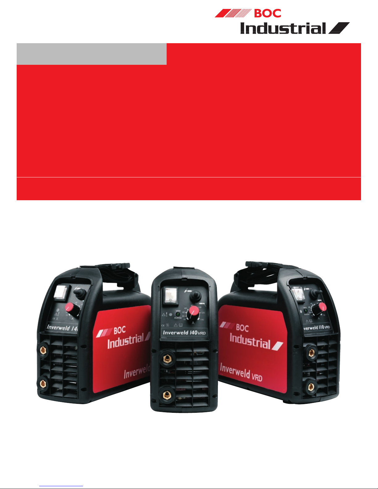
2.0 MMA Welding Principle
Manual Metal Arc (MMA*) welding is a fusion
welding process which uses the heat of an arc
formed between the consumable electrode and
the workpiece to melt the joint area. The arc
and the weld pool are shielded by gases and
slags that result from the decomposition of the
coating material that surrounds the electrode.
The electrode material is transferred across the
arc to fill the joint and must be continuously
fed forward by the operator to maintain a
constant arc length. The principle of the process
is illustrated below.
MMA welding applications
Manual metal arc welding is used for:
• structural steel work
• steel bridges
• pressure vessels
• tanks
• general fabrication
• earth moving equipment
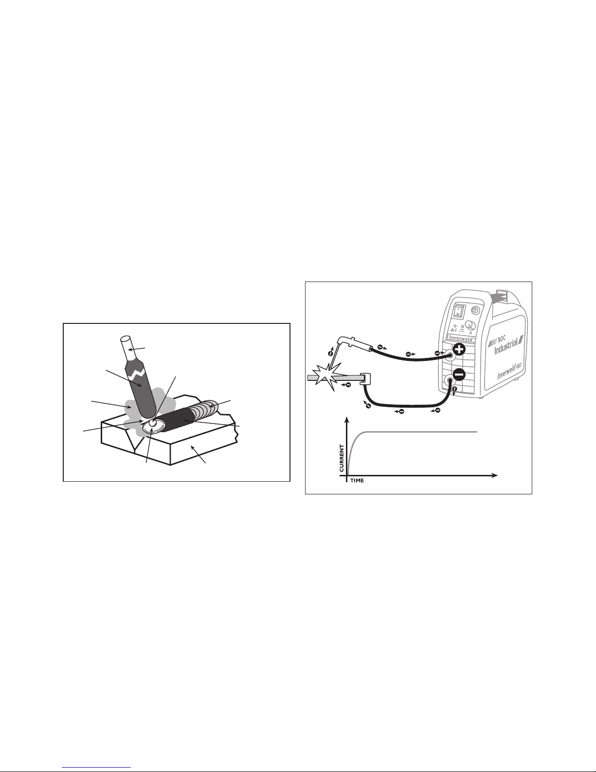
2.1 Fundamental Equipment
Requirements
The basic arrangement of the MMA welding
system is shown in figure 2 and consists of:
• a welding power source
• electrode holder
• welding cables
Basic arrangement of DC MMAW
equipment
Note:
The electrode may be connected to either the
positive (+) or the negative (–) connection on
the BOC Inverweld front panel.
Connecting the electrode to the positive
(DCEP) and the work clamp to the negative
will result in deeper weld metal penetration.
Connecting the electrode to the negative
(DCEN) and the work clamp to the positive
will result in a flatter and wider weld bead
profile with less penetration than the electrode
positive connection.
6
2. Manual Metal Arc Welding (MMAW)
*Commonly referred to as Stick Welding.
-ETALDROPLETCOVERED
WITHMOLTENSLAG
'ASEOUS
SHIELD
3OLIDIFIEDSLAG
7ELDMETAL
0A
RENTMETAL7ELDPOOL
!RC
&LUXCOATED
ELECTRODE
#OREWIRE

2.2 Control of the Process
The main control parameters for the MMA
process are:
• current and
• operator technique
The current range is determined by the
electrode type and size. Deposition rate
increases with current for a given electrode
diameter but the maximum current is limited by
the coating material and the ability to control
both the weld pool and the molten slag.
Increasing the current also increases the level of
fume and the arc radiation. A high level of manual
dexterity is required to coordinate the movement
of the electrode to match the burn-off rate and
maintain a constant arc length. Some electrodes
are designed for 'touch' or contact welding (the
electrode coating rests on the workpiece during
welding) and this simplifies the production of
fillet welds. Additional skills are required to
control fusion characteristics and bead profile
(electrode angle, travel speed and weave patterns
must be carefully chosen), particularly for
positional welding.
2.3 Features of the Process
The most important characteristic of the
MMAW process is its overall flexibility. The wide
range of electrode types allows the weld metal
to be matched to the application, which may be
particularly useful in repair and jobbing shop
environments. Relatively simple equipment is
required and the capital cost is low.
The quality of the welded joint depends almost
entirely on the welder, and availability of
suitably qualified welders may cause production
bottlenecks. In addition the process is
intermittent, as the electrode must be changed
at regular intervals, placing a natural limit on the
productivity of the process.
2.4 Applications of MMA Welding
The process is applied widely in the fabrication
and repair of plain carbon and low alloy steels.
It has been used in the construction of power
stations, pipelines and offshore structures.
Stainless steel, inconel, nickel and a wide
range of surfacing electrodes are available, and
these may be used in low volume production,
maintenance and repair situations.
2.5 MMA Electrode
Characteristics
The characteristics of the MMAW process are
largely determined by the electrode coating
material that controls the following important
features:
Arc
Certain chemicals may be added to the coating
material to stabilise the arc (e.g. rutile or potassium
silicate), improve metal transfer and reduce spatter.
These additions also provide a useful reduction
in the operating voltage required for the electrode.
Shielding
Shielding is provided by gases generated by the
decomposition of constituents such as calcium
carbonate or cellulose and by liquid slags which
protect the weld pool surface.
Weld pool control
The slag fluidity is usually the factor that
determines the ease of positional welding. Rapidly
freezing slags may be used to provide support
for the weld pool in vertical and overhead welding.
Alloying
The coating material can provide a useful source
of alloying elements or additions that control the
weld metal chemistry (such as deoxidisers). This
enables a wide range of weld metal properties to
be achieved by modifying the coating whilst using
a standard core wire.
7

2.6 Electrode Types
A range of well established electrode types are
available for the welding of ferrous materials,
and these are usually classified in the following
groups:
• cellulosic
• rutile
• basic, iron powder,
• others
Cellulosic electrodes contain over 30%
organic material (e.g. cellulose) in the coating.
This decomposes in the arc to generate
hydrogen and carbon dioxide. High arc forces
are formed in the arc and these depress the
weld pool and produce deep penetration
characteristics. The arc force may also be used
to generate a 'keyhole' effect that may be used
to complete single sided root runs, particularly
in pipe. It is usually these types of electrodes
that are use in the "Stovepipe" method of
welding.
Rutile electrodes contain the principal alloying
element titanium dioxide (TiO2 i.e. rutile).
This addition gives excellent arc stability, low
voltages, low spatter and easily controlled selfdetaching slag. These characteristics make the
rutile electrode the most common generalpurpose electrode type.
Basic (Low Hydrogen) electrodes usually
contain calcium carbonate (CaCO3) and
calcium fluoride (CaF2). The hydrogen content
of the coating is controlled by the absence of
minerals containing combined water and careful
baking procedures. In general, the arc running
characteristics of these electrodes are inferior
to those of the rutile types described above, but
the mechanical properties of the weld metal are
superior. These electrodes are used on ferritic
steels when resistance to hot and cold cracking
is required.
Iron powder may be added to any of the above
coating types to increase the 'recovery' or the
amount of filler material produced when the
electrode is used. The addition of iron powder
also increases the deposition rate and usually
reduces the arc voltage requirement.
Iron oxide/silicate electrode formulations
may be used for general purpose mild steel
welding in the flat and HV positions but these
types have largely been superseded by rutile
coatings.
In addition to electrodes for plain carbon, low
alloy and high alloy steels a range of surfacing
and non-ferrous alloy electrodes are available.
2.7 Care of Electrodes
The performance of MMA electrodes and
the quality of the resultant weld depend on
the type of electrode and its condition. If the
mineral coating is damaged or chipped, poor
arc stability and inadequate shielding may
result. Most coating materials absorb moisture
if not properly protected and this may result
in deterioration of the coating and hydrogen
pick up in the weld bead. Particular care must
be taken with controlled hydrogen electrodes
that should be stored and if necessary re-dried
according to the manufacturers instructions.
Poor electrode condition will often be indicated
by increased spatter, striking difficulties, weld
bead porosity, and 'harsh' arcing characteristics.
8
 Loading...