

Page 1
MIG 250C
Operating manual
6PRRWKDUF
$GYDQFH$GYDQFH
,,
Machine comes with side tray
Page 2

2
BOC Smootharc Advance II MIG 250C Operating manual
Welcome to a better way of welding.
This operating manual provides the basic knowledge required for MIG
Welding, as well as highlighting important areas of how to operate the
Smootharc ADVANCE machines.
With normal use and by following these recommended steps, your
Smootharc ADVANCE machine can provide you with years of troublefree service. Smootharc ADVANCE equipment and technical support is
available through the national BOC Customer Service Centre or contact
your local Gas & Gearoutlet.
Important Notice
This document has been prepared by BOC Limited ABN 95 000 029 729 (‘BOC’), as general information and does not contain and is not to be taken as containing any specic recommendation. The document has been prepared in good faith
and is professional opinion only. Information in this document has been derived from third parties, and though BOC believes it to be reliable as at the time of printing, BOC makes no representation or warranty as to the accuracy, reliability or
completeness of information in this document and does not assume any responsibility for updating any information or correcting any error or omission which may become apparent after the document has been issued. Neither BOC nor any of its
agents has independently veried the accuracy of the information contained in this document. The information in this document is commercial in condence and is not to be reproduced. The recipient acknowledges and agrees that it must make
its own independent investigation and should consider seeking appropriate professional recommendation in reviewing and evaluating the information. This document does not take into account the particular circumstances of the recipient and
the recipient should not rely on this document in making any decisions, including but not limited to business, safety or other operations decisions. Except insofar as liability under any statute cannot be excluded, BOC and its aliates, directors,
employees, contractors and consultants do not accept any liability (whether arising in contract, tort or otherwise) for any error or omission in this document or for any resulting loss or damage (whether direct, indirect, consequential or otherwise)
suered by the recipient of this document or any other person relying on the information contained herein. The recipient agrees that it shall not seek to sue or hold BOC or their respective agents liable in any such respect for the provision of this
document or any other information.
Page 3

3BOC Smootharc Advance II MIG 250C Operating manual
Contents.
1.0 Recommended Safety Guidelines andPrecautions 4
1.1 Health Hazard Information 5
1.2 Personal Protection 5
1.3 Electrical shock 6
1.4 User Responsibility 6
2.0 MIG Process 7
2.1 Introduction to Metal Inert Gas (MIG) 7
2.2 Introduction to Flux Cored Arc Welding (FCAW) 7
2.3 Introduction to Metal Cored Arc Welding (MCAW) 9
2.4 Fundamentals of MIG, FCAW and MCAW 12
3.0 MMA Process 14
3.1 Introduction 14
3.2 Process 14
3.3 Welding Machine 14
3.4 Welding Technique 15
3.5 Electrode Selection 15
3.6 Types of Joints 18
3.7 Fillet Welds 19
3.8 Typical Defects Due to FaultyTechnique 21
4.0 General Welding Information 23
4.1 Recommended Welding Parameters 23
5.0 Correct Application Techniques 25
6.0 Package Contents 27
7.0 Installation 28
7.1 Installation for MIG/MAG process 28
7.2 Installation for MMA process 28
8.0 Operation Set-up 29
8.1 MIG Welding Set-up 29
8.2 MMA Welding Set-up 29
9.0 Control Panel 30
9.1 Controls 30
9.2 Inductance 31
9.3 4T/2T Trigger Latch Selection 31
10.0 Troubleshooting and Fault Finding 32
11.0 Replacement Parts 33
12.0 Periodic Maintenance 34
12.1 Power Source 34
13.0 Technical Specications 35
14.0 Warranty Information 36
14.1 Terms of Warranty 36
14.2 Limitations on Warranty 36
14.3 Warranty Period 36
14.4 Warranty Repairs 36
Page 4
4
BOC Smootharc Advance II MIG 250C Operating manual
1.0 Recommended Safety Guidelines
andPrecautions
Some safety precautions BOC
recommends are as follows:
→ Repair or replace defective cables immediately.
→ Never watch the arc except through
lenses of the correct shade.
→ In conned spaces, adequate ventilation
and constant observation are essential.
→ Leads and cables should be kept clear
of passageways.
→ Keep re extinguishing equipment at a handy location
in the workshop.
→ Keep primary terminals and live parts eectively covered.
→ Never strike an arc on any gas cylinder.
→ Never use oxygen for venting containers.
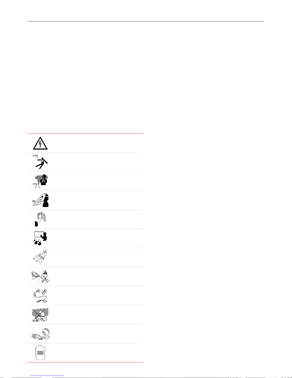
Diagram and safety explanation
Electrical safety alert
Welding electrode causing electric shock
Fumes and gases coming from welding process
Welding arc rays
Read instruction manual
Become trained
Wear dry, insulated gloves
Insulate yourself from work and ground
Disconnect input power before working on equipment
Keep head out of fumes
Use forced ventilation or local exhaust to remove fumes
Use welding helmet with correct shade of lter
Page 5

5BOC Smootharc Advance II MIG 250C Operating manual
1.1 Health Hazard Information
The actual process of MIG welding is one that can cause a variety of
hazards. All appropriate safety equipment should be worn at all times,
i.e. headwear, hand and body protection. Electrical equipment should be
used in accordance with the manufacturer’s recommendations.
Eyes
The process produces ultra violet rays that can injure and cause
permanent damage. Fumes can cause irritation.
Skin
Arc rays are dangerous to uncovered skin.
Inhalation
Welding fumes and gases are dangerous to the health of the operator
and to those in close proximity. The aggravation of pre-existing
respiratory or allergic conditions may occur in some workers. Excessive
exposure may cause conditions such as nausea, dizziness, dryness and
irritation of eyes, nose and throat.
1.2 Personal Protection
Respiratory
Conned space welding should be carried out with the aid of a fume
respirator or air supplied respirator as per AS/NZS 1715 and AS/NZS
1716 Standards.
→ You must always have enough ventilation in conned spaces. Be alert
to this at all times.
→ Keep your head out of the fumes rising from the arc.
→ Fumes from the welding of some metals could have an adverse eect
on your health. Don’t breathe them in. If you are welding on material
such as stainless steel, nickel, nickel alloys or galvanised steel,
further precautions are necessary.
→ Wear a respirator when natural or forced ventilation is not sucient.
Eye protection
A welding helmet with the appropriate welding lter lens for the
operation must be worn at all times in the work environment. The
welding arc and the reecting arc ash gives out ultraviolet and infrared
rays. Protective welding screen and goggles should be provided for
others working in the same area.
Recommended lter shades for arc welding
Less than 150 amps Shade 10*
150 to 250 amps Shade 11*
250 to 300 amps Shade 12
300 to 350 amps Shade 13
Over 350 amps Shade 14
*Use one shade darker for aluminium.
Clothing
Suitable clothing must be worn to prevent excessive exposure to UV
radiation and sparks. An adjustable helmet, ameproof loose-tting
cotton clothing buttoned to the neck, protective leather gloves, spats,
apron and steel capped safety boots are highly recommended.
Page 6

6
BOC Smootharc Advance II MIG 250C Operating manual
1.3 Electrical shock
→ Never touch ‘live’ electrical parts
→ Always repair or replace worn or damagedparts
→ Disconnect power source before performingany maintenance or
service
→ Earth all work materials
→ Never work in moist or damp areas
Avoid electric shock by:
→ Wearing dry insulated boots.
→ Wearing dry leather gloves.
→ Working on a dry insulated oor where possible.
1.4 User Responsibility
→ Read the Operating Manual prior to installation of this machine.
→ Unauthorised repairs to this equipment may endanger the technician
and operator and will void your warranty. Only qualied personnel
approved by BOC should perform repairs.
→ Always disconnect mains power before investigating
equipmentmalfunctions.
→ Parts that are broken, damaged, missing or worn should be
replacedimmediately.
→ Equipment should be cleaned periodically.
BOC stock a huge range of personal protective equipment. This combined
with BOC’s extensive Gas and Gear network ensures fast, reliable service
throughout the South Pacic.
STOP
PLEASE NOTE that under no circumstances should any
equipment or parts be altered or changed in any way from
the standard specication without written permission given
byBOC. To do so will void the EquipmentWarranty.
Further information can be obtained from Welding Institute of Australia
(WTIA) Technical Note No.7.
Health and Safety Welding
Published by WTIA,
PO Box 6165 Silverwater NSW 2128
Phone (02) 9748 4443
Page 7
7BOC Smootharc Advance II MIG 250C Operating manual
2.0 MIG Process
2.1 Introduction to Metal Inert Gas (MIG)
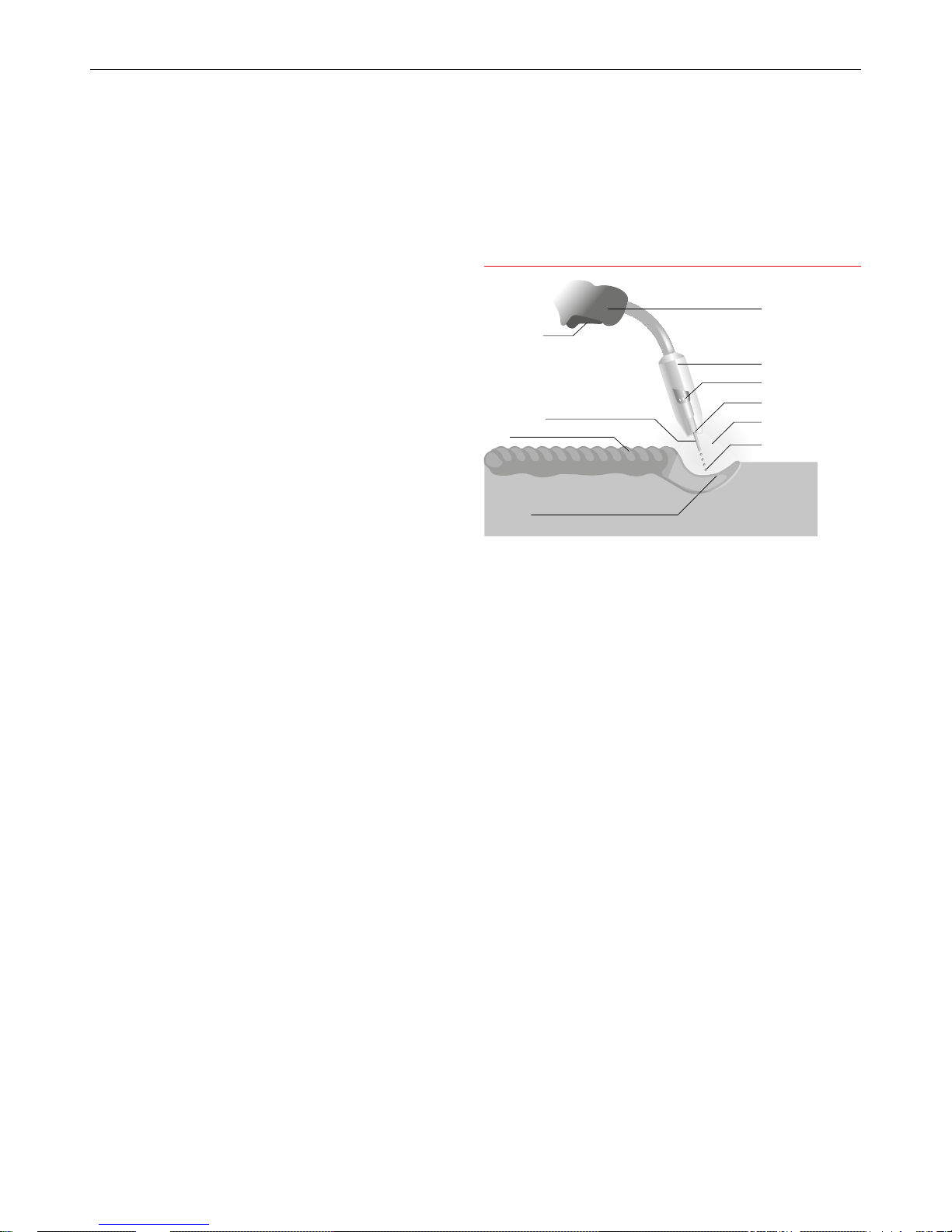
MIG welding embraces a group of arc welding processes in which a
continuous electrode (the wire) is fed by powered feed rolls (wire
feeder) into the weld pool. An electric arc is created between the tip of
the wire and the weld pool. The wire is progressively melted at the same
speed at which it is being fed and forms part of the weld pool. Both the
arc and the weld pool are protected from atmospheric contamination by
a shield of inert (non-reactive) gas, which is delivered through a nozzle
that is concentric with the welding wire guide tube.
Operation
MIG welding is usually carried out with a handheld torch as a semiautomatic process. The MIG process can be suited to a variety of job
requirements by choosing the correct shielding gas, electrode (wire) size
and welding parameters. Welding parameters include the voltage, travel
speed, arc (stick-out) length and wire feed rate. The arc voltage and wire
feed rate will determine the ller metal transfer method.
This application combines the advantages of continuity, speed,
comparative freedom from distortion and the reliability of automatic
welding with the versatility and control of manual welding. The process
is also suitable for mechanised set-ups, and its use in this respect
isincreasing.
MIG welding can be carried out using solid wire, ux cored, or a copper-
coated solid wire electrode. The shielding gas or gas mixture may consist
of the following:
→ Argon
→ Carbon dioxide
→ Argon and carbon dioxide mixtures
→ Argon mixtures with oxygen or helium mixtures
Each gas or gas mixture has specic advantages and limitations. Other
forms of MIG welding include using a ux-cored continuous electrode
and carbon dioxide shielding gas, or using self-shielding ux-cored wire,
requiring no shielding gas.
2.2 Introduction to Flux Cored
Arc Welding (FCAW)
How it Works
Flux-cored arc welding (FCAW) uses the heat generated by a DC electric
arc to fuse the metal in the joint area, the arc being struck between a
continuously fed consumable ller wire and the workpiece, melting both
the ller wire and the workpiece in the immediate vicinity. The entire arc
area is covered by a shielding gas, which protects the molten weld pool
from the atmosphere.
FCAW is a variant of the MIG process and while there are many common
features between the two processes, there are also several fundamental
dierences.
As with MIG, direct current power sources with constant voltage output
characteristics are normally employed to supply the welding current.
With ux-cored wires the terminal that the ller wire is connected
to depends on the specic product being used, some wires running
electrode positive, others running electrode negative. The work return
is then connected to the opposite terminal. It has also been found that
the output characteristics of the power source can have an eect on the
quality of the welds produced.
The wire feed unit takes the ller wire from a spool, and feeds it
through the welding torch, to the arc at a predetermined and accurately
controlled speed. Normally, special knurled feed rolls are used with ux-
cored wires to assist feeding and to prevent crushing the consumable.
Typical MIG set up
Torch trigger
Welding wire
Weld
Weld pool
Torch
Shroud
Gas diuser
Contact tip
Shielding
Droplets
Page 8
8
BOC Smootharc Advance II MIG 250C Operating manual
Unlike MIG, which uses a solid consumable ller wire, the consumable
used in FCAW is of tubular construction, an outer metal sheath being
lled with uxing agents plus metal powder. The ux ll is also used to
provide alloying, arc stability, slag cover, de-oxidation, and, with some
wires, gas shielding.
In terms of gas shielding, there are two dierent ways in which this may
be achieved with the FCAW process.
→ Additional gas-shielding supplied from an external source, such as a
gas cylinder
→ Production of a shielding gas by decomposition of uxing agents
within the wire, self-shielding
Gas shielded wires are available with either a basic or rutile ux ll,
while self-shielded wires have a broadly basic-type ux ll. The ux
ll dictates the way the wire performs, the properties obtainable, and
suitable applications.
Gas-shielded Operation
Many cored wire consumables require an auxiliary gas shield in the
same way that solid wire MIG consumables do. These types of wire are
generally referred to as ‘gas-shielded’.
Using an auxiliary gas shield enables the wire designer to concentrate
on the performance characteristics, process tolerance, positional
capabilities, and mechanical properties of the products.
In a ux cored wire the metal sheath is generally thinner than that of
a self-shielded wire. The area of this metal sheath surrounding the ux
cored wire is much smaller than that of a solid MIG wire. This means that
the electrical resistance within the ux cored wire is higher than with
solid MIG wires and it is this higher electrical resistance that gives this
type of wire some of its novel operating properties.
One often quoted property of uxed cored wires are their higher
deposition rates than solid MIG wires. What is often not explained is how
they deliver these higher values and whether these can be utilised. For
example, if a solid MIG wire is used at 250 amps, then exchanged for a
ux cored wire of the same diameter, and welding power source controls
are left unchanged, then the current reading would be much less than
250 amps, perhaps as low as 220 amps. This is because of Ohms Law
that states that as the electrical resistance increases if the voltage
remains stable then the current must fall.
To bring the welding current back to 250 amps it is necessary to
increase the wire feed speed, eectively increasing the amount of
wire being pushed into the weld pool to make the weld. It is this aect
that produces the ‘higher deposition rates’ that the ux cored wire
manufacturers claim for this type of product. Unfortunately in many
instances the welder has diculty in utilising this higher wire feed speed
and must either increase the welding speed or increase the size of the
weld. Often in manual applications neither of these changes can be
implemented and the welder simply reduces the wire feed speed back
to where it was and the advantages are lost. However, if the process
is automated in some way then the process can show improvements in
productivity.
It is also common to use longer contact tip to workpiece distances with
ux cored arc welding than with solid wire MIG welding and this also
has the eect of increasing the resistive heating on the wire further
accentuating the drop in welding current. Research has also shown
that increasing this distance can lead to an increase in the ingress of
nitrogen and hydrogen into the weld pool, which can aect the quality
of the weld.
Flux cored arc welding has a lower eciency than solid wire MIG welding
because part of the wire ll contains slag forming agents. Although the
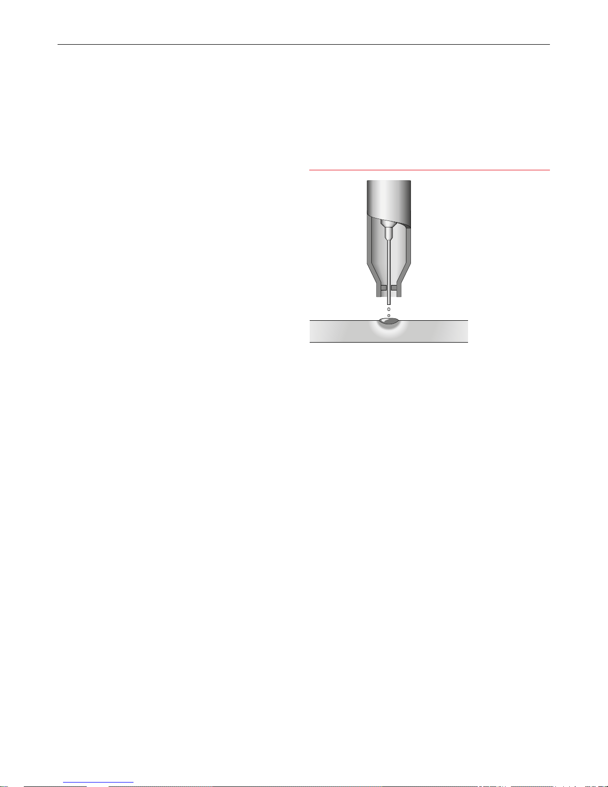
Extended self shielded ux cored wire nozzle
Page 9
9BOC Smootharc Advance II MIG 250C Operating manual
eciency diers by wire type and manufacturer it is typically between
75–85%.
Flux cored arc welding does, however, have the same drawback as solid
wire MIG in terms of gas disruption by wind, and screening is always
necessary for site work. It also incurs the extra cost of shielding gas, but
this is often outweighed by gains in productivity.
Self-shielded Operation
There are also self-shielded consumables designed to operate without
an additional gas shield. In this type of product, arc shielding is provided
by gases generated by decomposition of some constituents within the
ux ll. These types of wire are referred to as ‘self-shielded’.
If no external gas shield is required, then the ux ll must provide
sucient gas to protect the molten pool and to provide de-oxidisers and
nitride formers to cope with atmospheric contamination. This leaves less
scope to address performance, arc stabilisation, and process tolerance,
so these tend to suer when compared with gas shielded types.
Wire eciencies are also lower, at about 65%, in this mode of operation
than with gas-shielded wires. However, the wires do have a distinct
advantage when it comes to site work in terms of wind tolerance, as
there is no external gas shield to be disrupted.
When using self-shielded wires, external gas supply is not required and,
therefore, the gas shroud is not necessary. However, an extension nozzle
is often used to support and direct the long electrode extensions that
are needed to obtain high deposition rates.
2.3 Introduction to Metal Cored
Arc Welding (MCAW)
How it Works
Metal-cored arc welding (MCAW) uses the heat generated by a DC
electric arc to fuse metal in the joint area, the arc being struck between
a continuously fed consumable ller wire and the workpiece, melting
both the ller wire and the workpiece in the immediate vicinity. The
entire arc area is covered by a shielding gas, which protects the molten
weld pool from the atmosphere.
As MCAW is a variant of the MIG welding process there are many
common features between the two processes, but there are also several
fundamental dierences.
As with MIG, direct current power sources with constant voltage output
characteristics are normally employed to supply the welding current.
With metal-cored wires the terminal the ller wire is connected to
depends on the specic product being used. Some wires are designed
to run on electrode positive, others preferring electrode negative, and
some which will run on either. The work return lead is then connected
to the opposite terminal. Electrode negative operation will usually give
better positional welding characteristics. The output characteristics
of the power source can have an eect on the quality of the welds
produced.
The wire feed unit takes the ller wire from a spool or bulk pack, and
feeds it through the welding torch, to the arc at a predetermined and
accurately controlled speed. Normally, special knurled feed rolls are used
with metal-cored wires to assist feeding and to prevent crushing the
consumable.
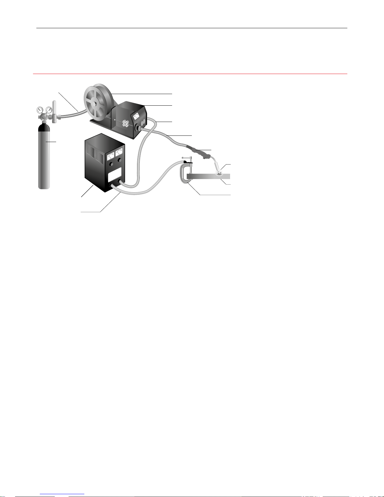
Gas hose
Gas cylinder
Power source
Return cable
Continous wire
Wire feed unit
Power cable
Torch conduit
Welding torch
Workpiece
Arc
Earth clamp
Process Schematic Diagram for MIG / FCAW and MCAW
Page 10
10
BOC Smootharc Advance II MIG 250C Operating manual
Unlike MIG, which uses a solid consumable ller wire, the consumable
used in MCAW is of tubular construction, an outer metal sheath being
lled entirely with metal powder except for a small amount of non-
metallic compounds. These are added to provide some arc stability and
de-oxidation.
MCAW consumables always require an auxiliary gas shield in the same
way that solid MIG wires do. Wires are normally designed to operate
in argon-carbon dioxide or argon-carbon dioxide-oxygen mixtures or
carbon dioxide. Argon rich mixtures tend to produce lower fume levels
than carbon dioxide.
As with MIG, the consumable ller wire and the shielding gas are
directed into the arc area by the welding torch. In the head of the torch,
the welding current is transferred to the wire by means of a copper alloy
contact tip, and a gas diuser distributes the shielding gas evenly around
a shroud which then allows the gas to ow over the weld area. The
position of the contact tip relative to the gas shroud may be adjusted to
limit the minimum electrode extension.
Modes of metal transfer with MCAW are very similar to those obtained in
MIG welding, the process being operable in both ‘dip transfer’ and ‘spray
transfer’ modes. Metal-cored wires may also be used in pulse transfer
mode at low mean currents, but this has not been widely exploited.
Modes of Metal Transfer
The mode or type of metal transfer in MIG welding depends upon the
current, arc voltage, electrode diameter and type of shielding gas used.
In general, there are four modes of metal transfer.
Modes of metal transfer with FCAW are similar to those obtained in MIG
welding, but here the mode of transfer is heavily dependent on the
composition of the ux ll, as well as on current and voltage.
The most common modes of transfer in FCAW are:
→ Dip transfer
→ Globular transfer
→ Spray transfer
→ Pulsed arc transfer operation has been applied to ux-cored wires
but, as yet, is not widely used because the other transfer modes are
giving users what they require, in most cases.
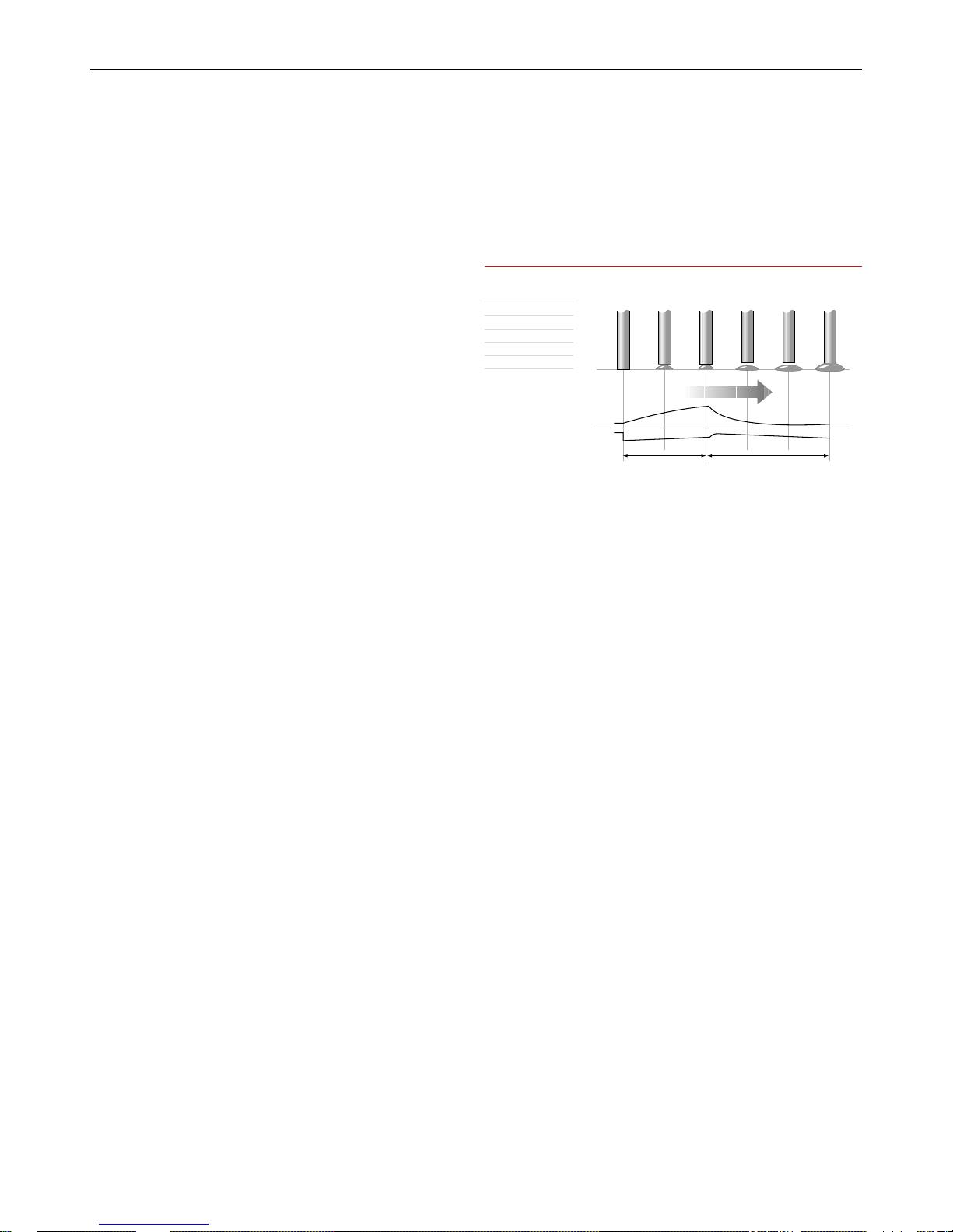
Dip Transfer
Also known as short-circuiting arc or short-arc, this is an all-positional
process, using low heat input. The use of relatively low current and arc
voltage settings cause the electrode to intermittently short-circuit with
the weld pool at a controlled frequency. Metal is transferred by the wire
tip actually dipping into the weld pool and the short-circuit current is
sucient to allow the arc to be re-established. This short-circuiting mode
of metal transfer eectively extends the range of MIG welding to lower
currents so thin sheet material can readily be welded. The low heat input
makes this technique well-suited to the positional welding of root runs
on thick plate, butt welds for bridging over large gaps and for certain
dicult materials where heat input is critical. Each short-circuit causes
the current to rise and the metal fuses o the end of the electrode. A
high short-circuiting frequency gives low heat input. Dip transfer occurs
between ±70-220A, 14–23 arc volts. It is achieved using shielding gases
based on carbon dioxide and argon.
Metal-cored wires transfer metal in dip mode at low currents just like
solid MIG wires. This transfer mode is used for all positional work with
these types of wire.
1 2 63 4 5
Time
Short circuit cycle Arcing cycle
Current (A)
Voltage (V)
1 Short circuit
2 Necking
3 Arc re-ignition
4 Arc established
5 Arc gap shortens
6 Short circuit
Schematic of Dip Transfer
Page 11
11BOC Smootharc Advance II MIG 250C Operating manual
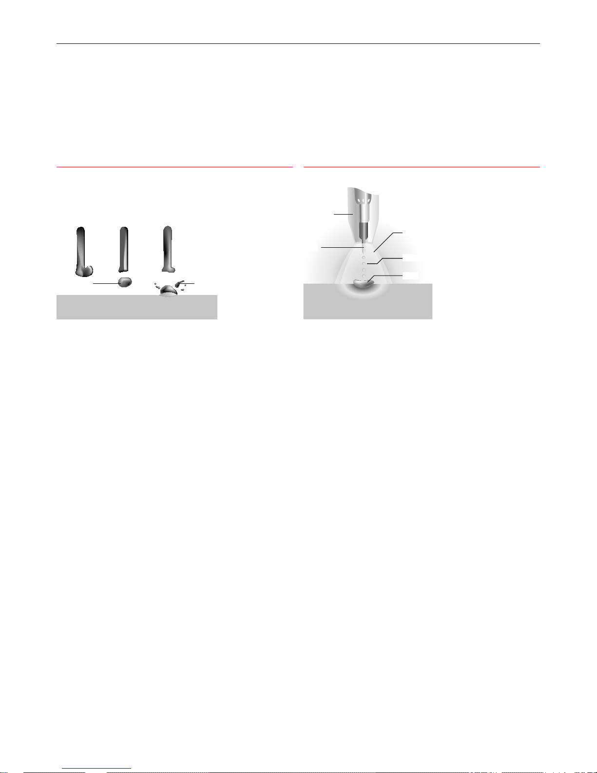
Globular Transfer
Metal transfer is controlled by slow ejection resulting in large,
irregularly-shaped ‘globs’ falling into the weld pool under the action
of gravity. Carbon dioxide gas drops are dispersed haphazardly. With
argon-based gases, the drops are not as large and are transferred in
a more axial direction. There is a lot of spatter, especially in carbon
dioxide, resulting in greater wire consumption, poor penetration and
poor appearance. Globular transfer occurs between the dip and spray
ranges. This mode of transfer is not recommended for normal welding
applications and may be corrected when encountered by either
decreasing the arc voltage or increasing the amperage. Globular transfer
can take place with any electrode diameter.
Basic ux-cored wires tend to operate in a globular mode or in a
globular-spray transfer mode where larger than normal spray droplets
are propelled across the arc, but they never achieve a true spray
transfer mode. This transfer mode is sometimes referred to as non-axial
globulartransfer.
Self-shielded ux-cored wires operate in a predominantly globular
transfer mode although at high currents the wire often ‘explodes’ across
the arc.
Spray Transfer
In spray transfer, metal is projected by an electromagnetic force from
the wire tip in the form of a continuous stream of discrete droplets
approximately the same size as the wire diameter. High deposition
rates are possible and weld appearance and reliability are good. Most
metals can be welded, but the technique is limited generally to plate
thicknesses greater than 6mm. Spray transfer, due to the tendency of
the large weld pool to spill over, cannot normally be used for positional
welding. The main exception is aluminium and its alloys where, primarily
because of its low density and high thermal conductivity, spray transfer
in position can be carried out.
The current ows continuously because of the high voltage maintaining
a long arc and short-circuiting cannot take place. It occurs best with
argon-based gases.
In solid wire MIG, as the current is increased, dip transfer passes into
spray transfer via a transitional globular transfer mode. With metalcored wires there is virtually a direct transition from dip transfer to spray
transfer as the current is increased.
For metal cored wire spray transfer occurs as the current density
increases and an arc is formed at the end of the ller wire, producing
a stream of small metal droplets. Often the outside sheath of the wire
will melt rst and the powder in the centre ows as a stream of smaller
droplet into the weld pool. This eect seems to give much better transfer
of alloying elements into the weld.
In spray transfer, as the current density increases, an arc is formed at
the end of the ller wire, producing a stream of small metal droplets.
In solid wire MIG this transfer mode occurs at higher currents. Fluxcored wires do not achieve a completely true spray transfer mode but
a transfer mode that is almost true spray may occur at higher currents,
and can occur at relatively low currents depending on the composition
of theux.
Rutile ux-cored wires will operate in this almost-spray transfer mode, at
all practicable current levels. They are also able to operate in this mode
for positional welding too. Basic ux-cored and self-shielded ux-cored
wires do not operate in anything approaching true spray transfer mode.
Large droplet
Splatter
Workpiece
Gas shroud
Wire
Shielding gas
Droplets
Weld
Workpiece
Schematic of Globular Transfer Schematic of Spray Transfer
Page 12

12
BOC Smootharc Advance II MIG 250C Operating manual
2.4 Fundamentals of MIG, FCAW and MCAW
Welding Technique
Successful welding depends on the following factors:
1 Selection of correct consumables
2 Selection of the correct power source
3 Selection of the correct polarity on the power source
4 Selection of the correct shielding gas
5 Selection of the correct application techniques
a Correct angle of electrode to work
b Correct electrical stickout
c Correct travel speed
6 Selection of the welding preparation
Selection of Correct Consumable
Chemical composition
As a general rule the selection of a wire is straightforward, in that it
is only a matter of selecting an electrode of similar composition to
the parent material. It will be found, however, that there are certain
applications that electrodes will be selected on the basis of its
mechanical properties or level of residual hydrogen in the weldmetal.
Solid MIG wires are all considered to be of the 'low Hydrogen type'
consumables.
The following table gives a general overview of the selection of some of
the BOC range of MIG wires for the most common materials.
Common Materials Welded with BOC MIG Wire
Material BOC MIG Wire
AS2074 C1,C2,C3, C4-1,C4-2,C5,C6 BOC Mild Steel MIG Wire
BS3100 AW1,A2,A3 BOC Mild Steel MIG Wire
BS1504-430,480,540 BOC Mild Steel MIG Wire
ASTM A36,A106,EN8,8A BOC Mild Steel MIG Wire
Stainless Steel
Grade 304 BOC Stainless Steel 308LSi
Grade 309 BOC Stainless Steel 309LSi
Grade 316 BOC Stainless Steel 316LSi
Physical condition
Surface condition
The welding wire must be free from any surface contamination including
mechanical damage such as scratch marks.
A simple test for checking the surface condition is to run the wire
through a cloth that has been dampened with acetone for 20 secs. If a
black residue is found on the cloth the surface of the wire is not properly
cleaned.
Cast and Helix
The cast and helix of the wire has a major inuence on the feedability of
MIG wire.
If the cast is too large the wire will move in an upward direction from the
tip when welding and if too small the wire will dip down from the tip.
The result of this is excessive tip wear and increased wear in the liners.
If the helix is too large the wire will leave the tip with a corkscrew eect.
Typical Metal Transfer Mode
Process
Dip
Transfer
Globular
Transfer
Spray Transfer
Metal Inert Gas
(MIG)
✓ ✕ ✓
Flux Cored
(Gas Shielded)
✓ ✓ ✓*
Flux Cored
(Self Shielded)
✓ ✓ ✕
Metal Cored
✓ ✕ ✓
* Not True Spray
Cast
Helix
Cast – Diameter of the circle
Helix – Vertical height
Cast and Helix
Page 13

13BOC Smootharc Advance II MIG 250C Operating manual
Selection of the Correct Power Source
Power sources for MIG welding is selected on a number of dierent
criteria, including:
1 Maximum output of the machine
2 Duty cycle
3 Output control (voltage selection, wire feed speed control)
4 Portability
The following table gives an indication of the operating amperage for
dierent size wires.
Wire Size Amperage Range (A)
0.8 mm 60–180
0.9 mm 70–250
1.0 mm 90–280
1.2 mm 120–340
Selection of the Correct Polarity on the Power Source
Many power sources are tted with an optional reverse polarity dinse
connector.
To achieve the optimum welding it is important to adhere to the
consumable manufacturer's instruction to select the polarity.
As a general rule all solid and metal cored wires are welded on electrode
positive. (Work return lead tted to the negative connector.)
Some grades of self shielded ux cored wires (i.e. E71T-11, E71T-GS etc)
need to be welded on electrode negative. (Work return lead tted to the
positive connector.)
Selection of the Correct Shielding Gas
The selection of the shielding gas has a direct inuence on the
appearance and quality of the weldbead.
The thickness of the material to be welded will determine the type of
shielding gas that has to be selected. As a general rule the thicker the
material (C-Mn and Alloy steels) are the higher the percentage of CO
2
in
the shielding gas mixture.
Dierent grades of shielding are required for materials such as stainless
steel, aluminium and copper.
The following table gives an indication of the most common shielding
gases used for Carbon Manganese and alloy steel.
Material thickness Recommended shielding gas
1–8 mm Argoshield® Light
5–12 mm Argoshield® Universal
>12 mm Argoshield® Heavy
More detailed selection charts, including recommendations for welding
parameters (voltage, amperage, electrical stickout, travelspeed and
gasow rate) can be found in the following pages.
Page 14
14
BOC Smootharc Advance II MIG 250C Operating manual
3.0 MMA Process
3.1 Introduction
Arc welding, although in the past principally the tool of tradesmen
and fabricators, has in recent years found increasing usage with small
workshops, farmers, handyman-hobbyists amongst others. This has
been brought about by the introduction of low-cost portable arc welding
machines and the ready availability of small diameter electrodes and
thinner section construction materials. Provided the operator isfamiliar
with the basic principles and techniques, arc welding can be a fast,
ecient and safe method of joining metals.
The main purpose of this manual is to help the welder with limited
experience to obtain a better understanding of the process, and to
acquire a reasonable degree of prociency in the least possible time.
Even welders with some experience will benet from the information in
this manual.
3.2 Process
Manual Metal Arc welding is the process of joining metals where an
electric arc is struck between the metal to be welded (parent metal) and
a ux-coated ller wire (the electrode). Theheat of the arc melts the
parent metal and the electrode which mix together to form, on cooling,
acontinuous solid mass.
Before arc welding can be carried out, a suitable power source is
required. Two types of power sources may be used for arc welding, direct
current (DC) or alternating current (AC).
The essential dierence between these two power sources is that, in the
case of DC, the current remains constant in magnitude and ows in the
same direction. Similarly, the voltage in the circuit remains constant in
magnitude and polarity (i.e. positive or negative).
In the case of AC however, the current ows rst in one direction and
then the other. Similarly, the voltage in the circuit changes from positive
to negative with changes in direction of current ow. This complete
reversal is called a ‘half cycle’ and repeats as long as the current
ows. The rate of change of direction of current ow is known as the
‘frequency’ of the supply and is measured by the number of cycles
completed per second. The standard frequency of the AC supply in
Australia is 50 Hz (Hertz).
3.3 Welding Machine
The most important consideration when contemplating the use of arc
welding for the rst time is the purchase of a suitable weldingmachine.
BOC supplies a popular range of arc welding machines. Machines
range from small portable welders that operate from standard
240Volt household power to heavy-duty welders used by the largest
steelfabricators.
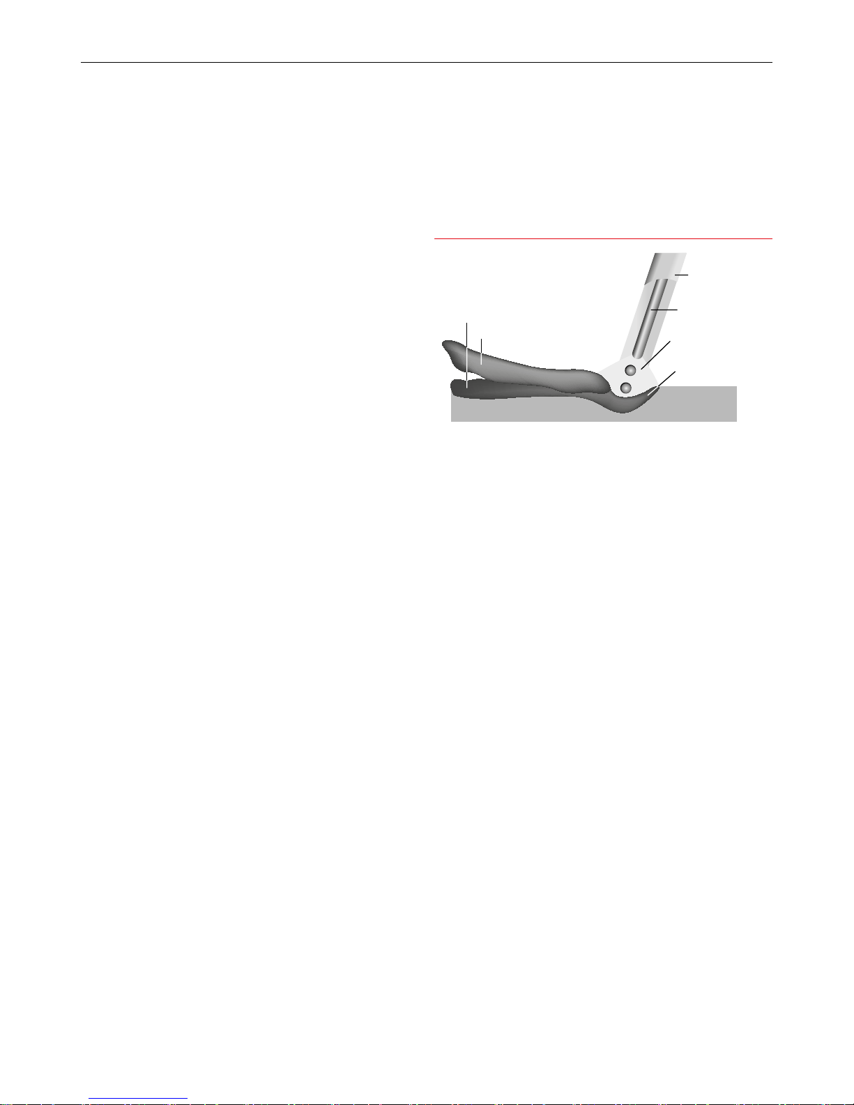
Basic Welding Machine and Cables
The choice of welding machine is based mostly on the following factors:
→ primary voltage, e.g. 240 Volt or 380 Volt
→ output amperage required, e.g. 140 amps
→ output required, e.g. AC or DC +/-
→ duty cycle required, e.g. 35% @ 140 amps
→ method of cooling, e.g. air-cooled or oil-cooled method of output
amperage control, e.g. tapped secondary lugs
→ or innitely variable control.
For example, the Smootharc 170 connects to 240 Volt supply (15 amps
Input), has an output of 170 amps DC @ 50% duty cycle.
Schematic of MMA process in operation
:HOG0HWDO
6ODJ
&RUH:LUH
)OX[&RYHULQJ
$UF
:HOG3RRO
:RUNSLHFH
Page 15

15BOC Smootharc Advance II MIG 250C Operating manual
Having decided on a welding machine, appropriate accessories are
required. These are items such as welding cables, clamps, electrode
holder, chipping hammer, helmet, shaded and clear lenses, scull cap,
gloves and other personal protective equipment.
BOC stocks a huge range of personal protective equipment. This
combined with BOC’s extensive network ensures fast reliable service
throughout the South Pacic.
3.4 Welding Technique
Successful welding depends on the followingfactors:
→ selection of the correct electrode
→ selection of the correct size of the electrodefor the job
→ correct welding current
→ correct arc length
→ correct angle of electrode to work
→ correct travel speed
→ correct preparation of work to be welded.
3.5 Electrode Selection
As a general rule the selection of an electrode is straight forward, in that
it is only a matter of selecting an electrode of similar composition to the
parent metal. It will be found, however, that for some metals there is a
choice of several electrodes, each of which has particular properties to
suit specic classes of work. Often, one electrode in the group will be
more suitable for general applications due to its all round qualities.
The table (on the next page) shows just a few of the wide range of
electrodes available from BOC with their typical areas of application.
For example, the average welder will carry out most fabrication using
mild steel and for this material has a choice of various standard BOC
electrodes, each of which will have qualities suited to particular tasks.
For general mild steel work, however, BOC Smootharc 13 electrodes
will handle virtually all applications. BOC Smootharc 13 is suitable for
welding mild steel in all positions using AC or DC power sources. Its easy-
striking characteristics and the tolerance it has for work where t-up
and plate surfaces are not considered good make it the most attractive
electrode of its class. Continuous development and improvement of
BOC Smootharc 13 has provided in-built operating qualities which
appeals to the beginner and experienced operator alike. For further
recommendations on the selection of electrodes for specic applications,
see table on the next page.
Page 16

16
BOC Smootharc Advance II MIG 250C Operating manual
Electrodes and Typical Applications
Name AWS
Class.
Application
BOC Smootharc 13 E6013 A premium quality electrode for general
structural and sheet metal work in all
positions including vertical down using
low carbon steels
BOC Smootharc 24 E7024 An iron powder electrode for high
speed welding for H-V llets and at
butt joints. Medium to heavy structural
applications in low carbon steels
BOC Smootharc 18 E7018-1 A premium quality all positional
hydrogen controlled electrode for
carbon steels in pressure vessel
applications and where high integrity
welding is required and for freemachining steels containing sulphur
BOC Smootharc S 308L E308L Rutile basic coated low carbon
electrodes for welding austenitic
stainless steel and dicult to weld
material
BOC Smootharc S 316L E316L
BOC Smootharc S 309L E309L Rutile basic coated low carbon electrode
for welding mild steel to stainless steel
and dicult to weld material
Electrode Size
The size of the electrode is generally dependent on the thickness of the
section being welded, and the larger the section the larger the electrode
required. In the case of light sheet the electrode size used is generally
slightly larger than the work being welded. This means that if 1.5 mm
sheet is being welded, 2.0 mm diameter electrode is the recommended
size. The following table gives the recommended maximum size of
electrodes that may be used for various thicknesses of section.
Recommended Electrode Sizes
Average Thickness
of Plate or Section
Maximum Recommended
Electrode Diameter
≤1.5 mm 2.0 mm
1.5–2.0 mm 2.5 mm
2.0–5.0 mm 3.15 mm
5.0–8.0 mm 4.0 mm
Welding Current
Correct current selection for a particular job is an important factor in arc
welding. With the current set too low, diculty is experienced in striking
and maintaining a stable arc. The electrode tends to stick to the work,
penetration is poor and beads with a distinct rounded prole will be
deposited.
Excessive current is accompanied by overheating of the electrode. It will
cause undercut, burning through of the material, and give excessive
spatter. Normal current for a particular job may be considered as the
maximum which can be used without burning through the work, overheating the electrode or producing a rough spattered surface, i.e. the
current in the middle of the range specied on the electrode package is
considered to be the optimum.
In the case of welding machines with separate terminals for dierent
size electrodes, ensure that the welding lead is connected to the correct
terminal for the size electrode being used. When using machines with
adjustable current, set on the current range specied.
The limits of this range should not normally be exceeded.
The following table shows the current ranges generally recommended
for BOC Smootharc13.
Page 17

17BOC Smootharc Advance II MIG 250C Operating manual
Generally Recommended Current Range for BOC Smootharc 13
Size of Electrode (mm) Current Range (Amp)
2.5 60–95
3.2 110–130
4.0 140–165
5.0 170–260
Arc Length
To start the arc, the electrode should be gently scraped on the work until
the arc is established. There is a simple rule for the proper arc length; it
should be the shortest arc that gives a good surface to the weld. An arc
too long reduces penetration, produces spatter and gives a rough surface
nish to the weld. An excessively short arc will cause sticking of the
electrode and rough deposits that are associated with slag inclusions.
For downhand welding, it will be found that an arc length not greater
than the diameter of the core wire will be most satisfactory. Overhead
welding requires a very short arc, so that a minimum of metal will be
lost. Certain BOC electrodes have been specially designed for ‘touch’
welding. These electrodes may be dragged along the work and a
perfectly sound weld is produced.
Electrode Angle
The angle which the electrode makes with the work is important to
ensure a smooth, even transfer of metal. The recommended angles
for use in the various welding positions are covered later.
Correct Travel Speed
The electrode should be moved along in the direction of the joint being
welded at a speed that will give the size of run required. At the same
time the electrode is fed downwards to keep the correct arc length
at all times. As a guide for general applications the table below gives
recommended run lengths for the downhand position.
Correct travel speed for normal welding applications varies between
approximately 125–375 mm per minute, depending on electrode size,
size of run required and the amperage used.
Excessive travel speeds lead to poor fusion, lack of penetration, etc.
Whilst too slow a rate of travel will frequently lead to arc instability, slag
inclusions and poor mechanical properties.
Run Length per Electrode – BOC Smootharc 13
Electrode
Size(mm)
Electrode
Length(mm)
Run Length (mm)
Minimum Maximum
4.0 350 175 300
3.2 350 125 225
2.5 350 100 225
Correct Work Preparation
The method of preparation of components to be welded will depend on
equipment available and relative costs. Methods may include sawing,
punching, shearing, lathe cut-os, ame cutting and others. In all
cases edges should be prepared for the joints that suit the application.
The following section describes the various joint types and areas of
application.
Page 18
18
BOC Smootharc Advance II MIG 250C Operating manual
3.6 Types of Joints
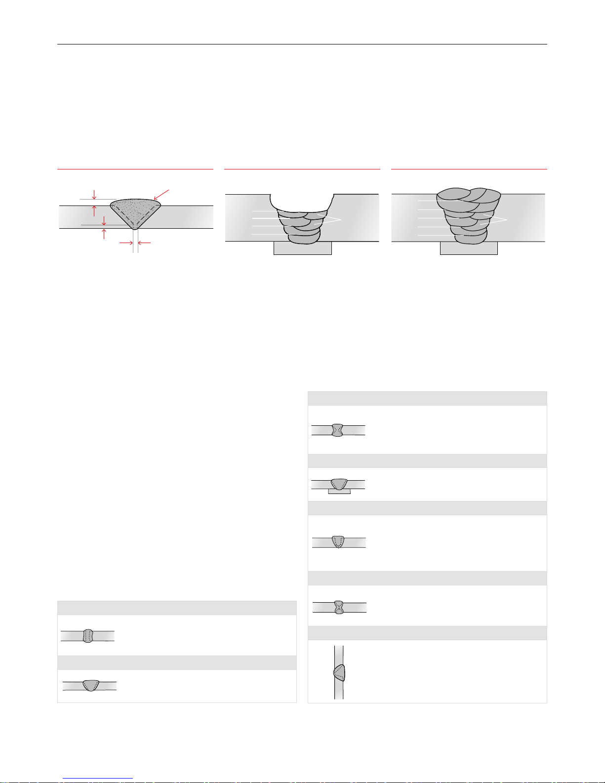
Butt Welds
A butt weld is a weld made between two plates so as to give continuity
of section. Close attention must be paid to detail in a butt weld to ensure
that the maximum strength of the weld is developed. Failure to properly
prepare the edges may lead to the production of faulty welds, as correct
manipulation of the electrode is impeded.
Two terms relating to the preparation of butt welds require explanation
at this stage. They are:
→ Root Face: the proportion of the prepared edge
that has not been bevelled.
→ Root Gap: the separation between root
faces of the parts to be joined.
Various types of butt welds are in common use and their suitability for
dierent thickness of steel are described as follows:
Square Butt Weld
The edges are not prepared but
are separated slightly to allow fusion through the full thickness
of the steel. Suitable for plate up
to 6 mm in thickness.
Single ‘V’ Butt Weld
This is commonly used for plate up to 16 mm in thickness and on
metal of greater thickness where access
is available from only one side.
Double ‘V’ Butt Weld
Used on plate of 12 mm and over in thickness when welding
can be applied from both sides. It allows faster welding and
greater economy of electrodes than a single ‘V’ preparation on
the same thickness of steel and also has less of a tendency to
distortion as weld contraction can be equalised.
Butt Weld with Backing Material
When square butt welds or single ‘V’ welds cannot be welded
from both sides it is desirable to use a backing bar to ensure
complete fusion.
Single ‘U’ Butt Weld
Used on thick plates an alternative to a single ‘V’ preparation. It
has advantages as regards speed of welding. It takes less weld
metal than a single ‘V’, there is less contraction and therefore a
lessened tendency to distortion. Preparation is more expensive
than in the case of a ‘V’, as machining is required. The type of
joint is most suitable for material over 40 mm in thickness.
Double ‘U’ Butt Weld
For use on thick plate that is accessible for welding from both
sides. For a given thickness it is faster, needs less weld metal
and causes less distortion than a single ‘U’ preparation.
Horizontal Butt Weld
The lower member in this case is bevelled to approximately 15°
and the upper member 45°, making an included angle of 60°.
This preparation provides a ledge on
the lower member, which tends
to retain the molten metal.
Electrode Angle for 1st and 2nd Layers Electrode Angle for Subsequent LayersButt Welding
Weld Face
Face Reinforcement
Root Face
Root Gap
Weld Beads
Layers
Weld Beads
Weld Beads
Layers
Layers
70˚ - 85˚
Electrode
Slag
Weld Pool
Weld Metal
Arc
Direction Of Welding
Page 19
19BOC Smootharc Advance II MIG 250C Operating manual
General notes on Butt Welds
The rst run in a prepared butt weld should be deposited with an
electrode not larger than 4.0 mm. The angle of the electrode for the
various runs in a butt weld is shown.
It is necessary to maintain the root gap by tacking at intervals or by
other means, as it will tend to close during welding.
All single ‘V’, single ‘U’ and square butt welds should have a backing
run deposited on the underside of the joint; otherwise 50% may be
deducted from the permissible working stress of the joint.
Before proceeding with a run on the underside of a weld it is necessary
to remove any surplus metal or under penetration that is evident on that
side of the joint.
Butt welds should be overlled to a certain extent by building up
the weld until it is above the surface of the plate. Excessive build-up,
however, should be avoided.
In multi-run butt welds it is necessary to remove all slag, and surplus
weld metal before a start is made on additional runs; this is particularly
important with the rst run, which tends to form sharp corners that
cannot be penetrated with subsequent runs. Electrodes larger than 4.0
mm are not generally used for vertical or overhead butt welds.
The diagrams following indicate the correct procedure for welding thick
plate when using multiple runs.
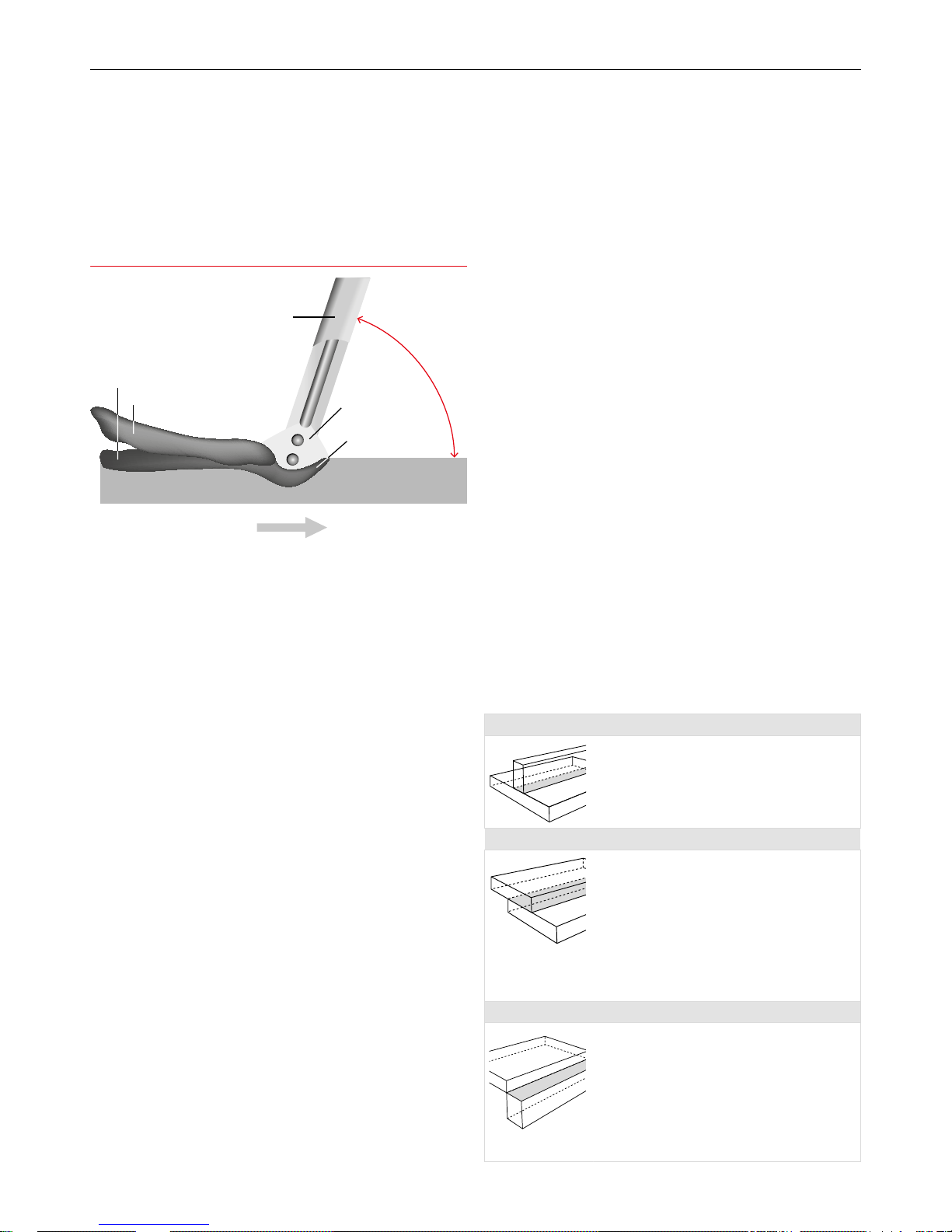
3.7 Fillet Welds
A llet weld is approximately triangular in section, joining two surfaces
not in the same plane and forming a lap joint, tee joint or corner joint.
Joints made with llet welds do not require extensive edge preparation,
as is the case with butt welded joints, since the weld does not
necessarily penetrate the full thickness of either member. It is important
that the parts to be joined be clean, close tting, and that all the edges
on which welding is to be carried out are square. On sheared plate it
is advisable to entirely remove any ‘false cut’ on the edges prior to
welding. Fillet welds are used in the following types of joints:
‘T’ Joints
A llet weld may be placed either on one or both sides,
depending on the requirements of the work. The weld metal
should fuse into or penetrate the corner formed between the
two members. Where possible the joint should be placed in
such a position as to form a “Natural ‘V’ llet” since this is the
easiest and fastest method of llet welding.
Lap Joints
In this case, a llet weld may be placed either on one or
both sides of the joint, depending on accessibility and the
requirements of the joint. However, lap joints, where only
one weld is accessible, should be avoided where possible and
must never constitute the joints of tanks or other fabrications
where corrosion is likely to occur behind the lapped plates.
Inapplying llet welds to lapped joints it is important that
the amount of overlap of the plates be not less than ve
times thethickness of the thinner part. Where it is required to
preserve the outside face or contour of a structure, one plate
may be joggled.
Corner Joints
The members are tted as shown, leaving a ‘V’-shaped
groove in which a llet weld is deposited. Fusion should be
complete for the full thickness of the metal. In practice it
is generally necessary to have a gap or a slight overlap on
the corner. The use of a 1.0–2.5 mm gap has the advantage
of assisting penetration at the root, although setting up is a
problem. The provision of an overlap largely overcomes the
problem of setting up, but prevents complete penetration
at the root and should therefore be kept to a minimum,
i.e.1.0–2.5 mm.
Welding Progression Angle
:HOG0HWDO
6ODJ
(OHFWURGH
$UF
:HOG3RRO
:RUNSLHFH
²Ý
'LUHFWLRQRI:HOGLQJ
Page 20
20
BOC Smootharc Advance II MIG 250C Operating manual
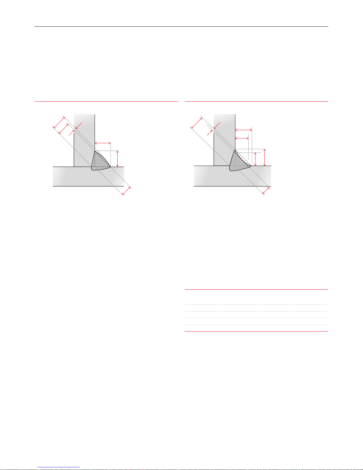
The following terms and denitions are important in specifying and
describing llet welds.
Leg Length
A fusion face of a llet weld, as shown above. All specications for llet
weld sizes are based on leg length.
Throat Thickness
A measurement taken through the centre of a weld from the root to the
face, along the line that bisects the angle formed by the members to
bejoined.
Eective throat thickness is a measurement on which the strength of a
weld is calculated. The eective throat thickness is based on a mitre llet
(concave Fillet Weld), which has a throat thickness equal to 70% of the
leg length. For example, in the case of a 20 mm llet, the eective throat
thickness will be 14 mm.
Convex Fillet Weld
A llet weld in which the contour of the weld metal lies outside a
straight line joining the toes of the weld. A convex llet weld of specied
leg length has a throat thickness in excess of the eective measurement.
Concave Fillet Weld
A llet in which the contour of the weld is below a straight line joining
the toes of the weld. It should be noted that a concave llet weld of
a specied leg length has a throat thickness less than the eective
throat thickness for that size llet. This means that when a concave llet
weld is used, the throat thickness must not be less than the eective
measurement. This entails an increase in leg length beyond the specied
measurement.
The size of a llet weld is aected by the electrode size, welding speed
or run length, welding current and electrode angle. Welding speed and
run length have an important eect on the size and shape of the llet,
and on the tendency to undercut.
Insucient speed causes the molten metal to pile up behind the arc
and eventually to collapse. Conversely, excessive speed will produce
a narrow irregular run having poor penetration, and where larger
electrodes and high currents are used, undercut is likely to occur.
Fillet Weld Data
Nominal Fillet
Size (mm)
Minimum Throat
Thickness (mm)
Plate Thickness
(mm)
Electrode Size
(mm)
5.0 3.5 5.0–6.3 3.2
6.3 4.5 6.3–12 4.0
8.0 5.5 8.0–12 & over 4.0
10.0 7.0 10 & over 4.0
Selection of welding current is important. If it is too high the weld
surface will be attened, and undercut accompanied by excessive spatter
is likely to occur. Alternatively, a current which is too low will produce a
rounded narrow bead with poor penetration at the root. The rst run in
the corner of a joint requires a suitably high current to achieve maximum
penetration at the root. A short arc length is recommended for llet
welding. The maximum size llet which should be attempted with one
pass of a large electrode is 8.0 mm. Eorts to obtain larger leg lengths
usually result in collapse of the metal at the vertical plate and serious
undercutting. For large leg lengths multiple run llets are necessary.
These are built up as shown. The angle of the electrode for various runs
in a downhand llet weld is shown on the next page.
Concave Fillet WeldConvex Fillet Weld
Actual Throat
Effective Throat
Convexity
Leg
Lengh
Theoretical Throat
Concavity
Actual Throat
& Effective Throat
Leg
Size
LegSize
Theoretical Throat
Concavity
Actual Throat
& Effective Throat
Leg
Size
LegSize
Theoretical Throat
Page 21
21BOC Smootharc Advance II MIG 250C Operating manual
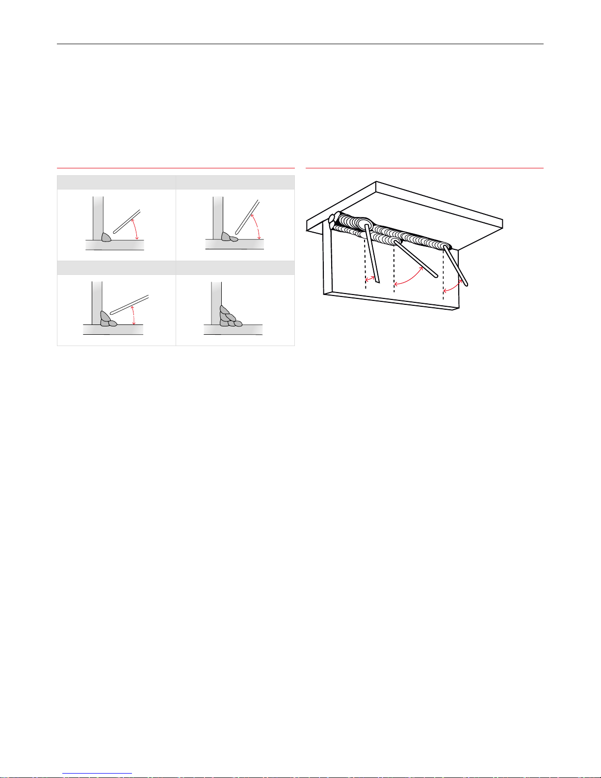
Recommended Electrode Angles for Fillet Welds
Multi-run horizontal llets have each run made using the same run
lengths (run length per electrode table). Each run is made in the same
direction, and care should be taken with the shape of each, so that it has
equal leg lengths and the contour of the completed llet weld
is slightly convex with no hollows in the face.
Vertical llet welds can be carried out using the upwards or downwards
technique. The characteristics of each are: upwards – current used is low,
penetration is good, surface is slightly convex and irregular. For multiple
run llets large single pass weaving runs can be used. Downwards –
current used is medium, penetration is poor, each run is small, concave
and smooth (only BOC Smootharc 13 is suitable for this position).
The downwards method should be used for making welds on thin
material only. Electrodes larger than 4.0 mm are not recommended
for vertical down welding. All strength joints in vertical plates 10.0
mm thick or more should be welded using the upward technique. This
method is used because of its good penetration and weld metal quality.
The rst run of a vertical up llet weld should be a straight sealing run
made with 3.15 mm or 4.0 mm diameter electrode. Subsequent runs
for large llets may be either numerous straight runs or several wide
weaving runs.
Correct selection of electrodes is important for vertical welding.
In overhead llet welds, careful attention to technique is necessary to
obtain a sound weld of good prole. Medium current is required for
best results. High current will cause undercutting and bad shape of
the weld, while low current will cause slag inclusions. To produce a
weld having good penetration and of good prole, a short arc length is
necessary. Angle of electrode for overhead llets is illustrated above.
3.8 Typical Defects Due to FaultyTechnique
Shielded metal arc welding, like other welding processes, has welding
procedure problems that may develop which can cause defects in the
weld. Some defects are caused by problems with the materials. Other
welding problems may not be foreseeable and may require immediate
corrective action. A poor welding technique and improper choice of
welding parameters can cause weld defects. Defects that can occur
when using the shielded metal arc welding process are slag inclusions,
wagon tracks, porosity, wormhole porosity, undercutting, lack of
fusion, overlapping, burn through, arc strikes, craters, and excessive
weld spatter. Many of these welding technique problems weaken the
weld and can cause cracking. Other problems that can occur which can
reduce the quality of the weld are arc blow, nger nailing, and improper
electrode coating moisture contents.
Defects caused by welding technique
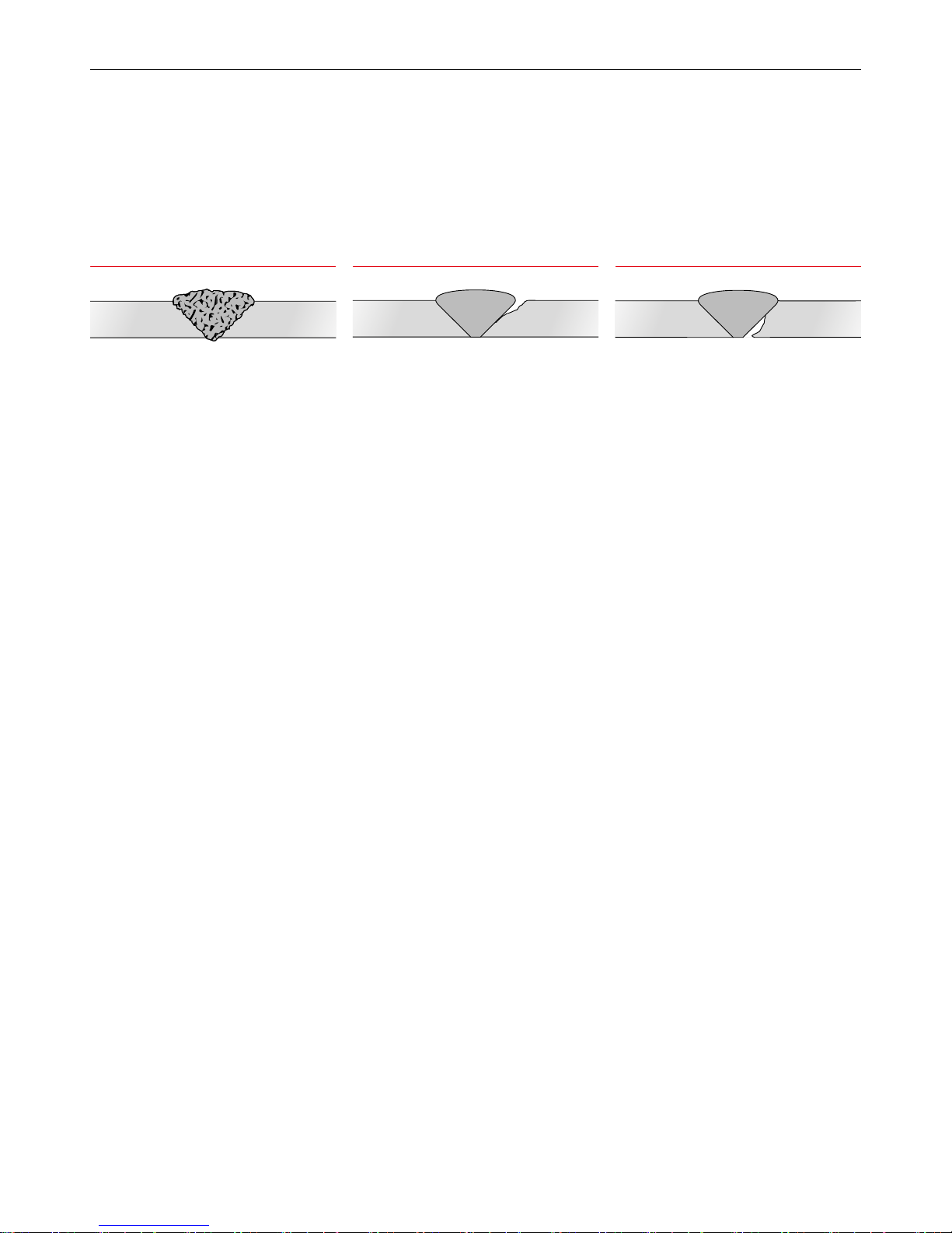
Slag Inclusions
Slag inclusions occur when slag particles are trapped inside the weld
metal which produces a weaker weld. These can be caused by:
→ erratic travel speed
→ too wide a weaving motion
→ slag left on the previous weld pass
→ too large an electrode being used
→ letting slag run ahead of the arc.
Recommended Angles for Overhead Fillet Welds Recommended Electrode Angles for Fillet Welds
1st Run 2nd Run
Electrode
40°
55–60°
55–60°
3rd Run Multi-run Fillet
Electrode
40°
55–60°
20–30°
1
2
3
4
5
6
55–60°
1
2
3
4
5
6
30˚
45˚
15˚
Page 22
22
BOC Smootharc Advance II MIG 250C Operating manual
This defect can be prevented by:
→ a uniform travel speed
→ a tighter weaving motion
→ complete slag removal before welding
→ using a smaller electrode
→ keeping the slag behind the arc which is done by shortening the arc,
increasing the travel speed, or changing the electrode angle.
Undercutting
Undercutting is a groove melted in the base metal next to the toe or
root of a weld that is not lled by the weld metal. Undercutting causes a
weaker joint and it can cause cracking.
This defect is caused by:
→ excessive welding current
→ too long an arc length
→ excessive weaving speed
→ excessive travel speed.
On vertical and horizontal welds, it can also be caused by too large
an electrode size and incorrect electrode angles. This defect can be
prevented by:
→ choosing the proper welding current for the type and size of
electrode and the welding position
→ holding the arc as short as possible
→ pausing at each side of the weld bead when a weaving technique is
used
→ using a travel speed slow enough so that the weld metal can
completely ll all of the melted out areas of the base metal.
Lack of Fusion
Lack of fusion is when the weld metal is not fused to the base metal.
This can occur between the weld metal and the base metal or between
passes in a multiple pass weld. Causes of this defect can be:
→ excessive travel speed
→ electrode size too large
→ welding current too low
→ poor joint preparation
→ letting the weld metal get ahead of the arc.
Lack of fusion can usually be prevented by:
→ reducing the travel speed
→ using a smaller diameter electrode
→ increasing the welding current
→ better joint preparation
→ using a proper electrode angle.
Undercutting Lack of FusionSlag Inclusions
Page 23

23BOC Smootharc Advance II MIG 250C Operating manual
4.0 General Welding Information
4.1 Recommended Welding Parameters
Argoshield® Light [Mild Steel Solid Wire]
Indicative
WeldingParameters Dip Transfer
Material thickness (mm) 1–1.6 2 3 4
Wire diameter (mm) 0.8–0.9 0.8–0.9 0.8–0.9 0.9–1.0
Voltage (volts) 14–16 16–17 16–18 16–18
Wire feed speed (m/min) 3.5–5.0 4.0–7.0 4.0–7.0 4.0–7.0
Gas rate ow (L/min) 15 15 15 15
Argoshield® Universal [Mild Steel Solid Wire]
Indicative
WeldingParameters Dip Transfer
Material thickness (mm) 4 6 8
Welding position Horizontal /
Vertical
Horizontal /
Vertical
Horizontal /
Vertical
Wire diameter (mm) 0.9–1.0 0.9–1.0 1.2
Current (amps) 120–160 140–160 140–160
Voltage (volts) 17–19 17–18 17–18
Wire feed speed (m/min) 4.0–5.2 4.0–5.0 3.2–4.0
Gas rate ow (L/min) 15 15 15
Page 24

24
BOC Smootharc Advance II MIG 250C Operating manual
Argon [Aluminium Solid Wire]
Indicative
WeldingParameters Solid Wire
Material thickness (mm) 4.0 5.0 8.0
Welding position
Horizontal Horizontal Horizontal
Wire diameter (mm)
1.2 1.2 1.2
Current (amps)
160–180 210–220 215–225
Voltage (volts)
21–23 22–24 22.5–24.5
Wire feed speed (m/min)
8.0–9.0 10.0–10.6 10.2–10.8
Gas rate ow (L/min)
18 18 18
Argoshield® 52 (Aus) or Argoshield® FCW (NZ) [Mild Steel Flux/Metal Cored Wire]
Indicative
WeldingParameters Metal Cored Wires Flux Cored Wires
Material thickness (mm) 10 12 12
Welding position
Horizontal Horizontal Vertical
Wire diameter (mm)
1.2 1.2 1.2
Current (amps)
200–250 200–250 175–200
Voltage (volts)
27–29 25–28 24–25
Wire feed speed (m/min)
6.9–10.0 9.1–13.1 7.5–9.1
Gas rate ow (L/min)
18 18 15
Stainshield® (Aus) or Stainshield® MIG (NZ) [Stainless Steel Solid Wire]
Indicative
WeldingParameters Dip Transfer Spray Transfer
Material thickness (mm) 4 6 8 4 6 10
Welding position
Horizontal /
Vertical
Horizontal /
Vertical
Horizontal /
Vertical Horizontal Horizontal Horizontal
Wire diameter (mm)
0.9–1.0 0.9–1.0 0.9–1.0 1.0 1.2 1.2
Current (amps)
100–125 120–150 120–150 180–220 260–280 260–310
Voltage (volts)
17–19 18–20 18–20 24–28 26–30 28–32
Wire feed speed (m/min)
5.0–6.5 6.0–7.5 6.0–8.0 7.0–9.0 8.0–10.0 9.0–11.0
Gas rate ow (L/min)
15 15 18 18 18 18
Page 25
25BOC Smootharc Advance II MIG 250C Operating manual
5.0 Correct Application Techniques
Electrical stickout
Correct Application Techniques
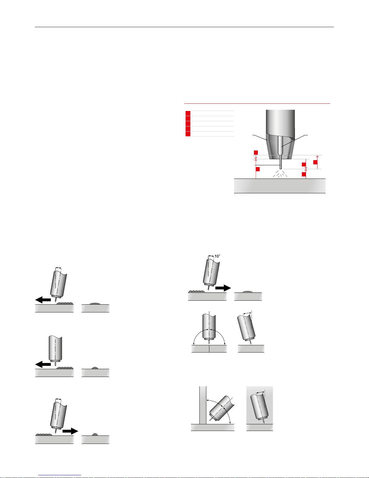
Direction of welding.
MIG welding with solid wires takes place normally with a push
technique. The welding torch is tilted at an angle of 10° towards the
direction of welding. (Push technique)
10°
The inuence of changing the torch angle and the welding direction on
the weld bead prole can be seen below.
Torch perpendicular to workpiece narrow bead width with increased
reinforcement.
10°
Torch positioned at a drag angle of 10° narrow bead with excessive
reinforcement.
Flux cored welding with cored wires takes place normally with the drag
technique. The welding torch is tilted at an angle of 10° away from the
direction of welding. For all other applications the torch angle remains
the same.
90° 90°
0–15°
Torch position for butt welds
When welding butt welds the torch should be positioned within the
centre of the groove and tilted at an angle of ±15° from the vertical
plane. Welding is still performed in the push technique.
0–15°
45°
45°
Torch position for llet welds
When welding llet welds the torch should be positioned at an angle of
45° from the bottom plate with the wire pointing into the llet corner.
Welding is still performed in the push technique.
C
Contact Tube Setback
S
Stando Distance
V
Visible Stickout
A
Arc length
E
Electrical Stickout
A
S
C
V
E
Contact Tube
Gas Nozzle
Consumable
Electrode
Workpiece
Page 26
26
BOC Smootharc Advance II MIG 250C Operating manual
Electrical stickout
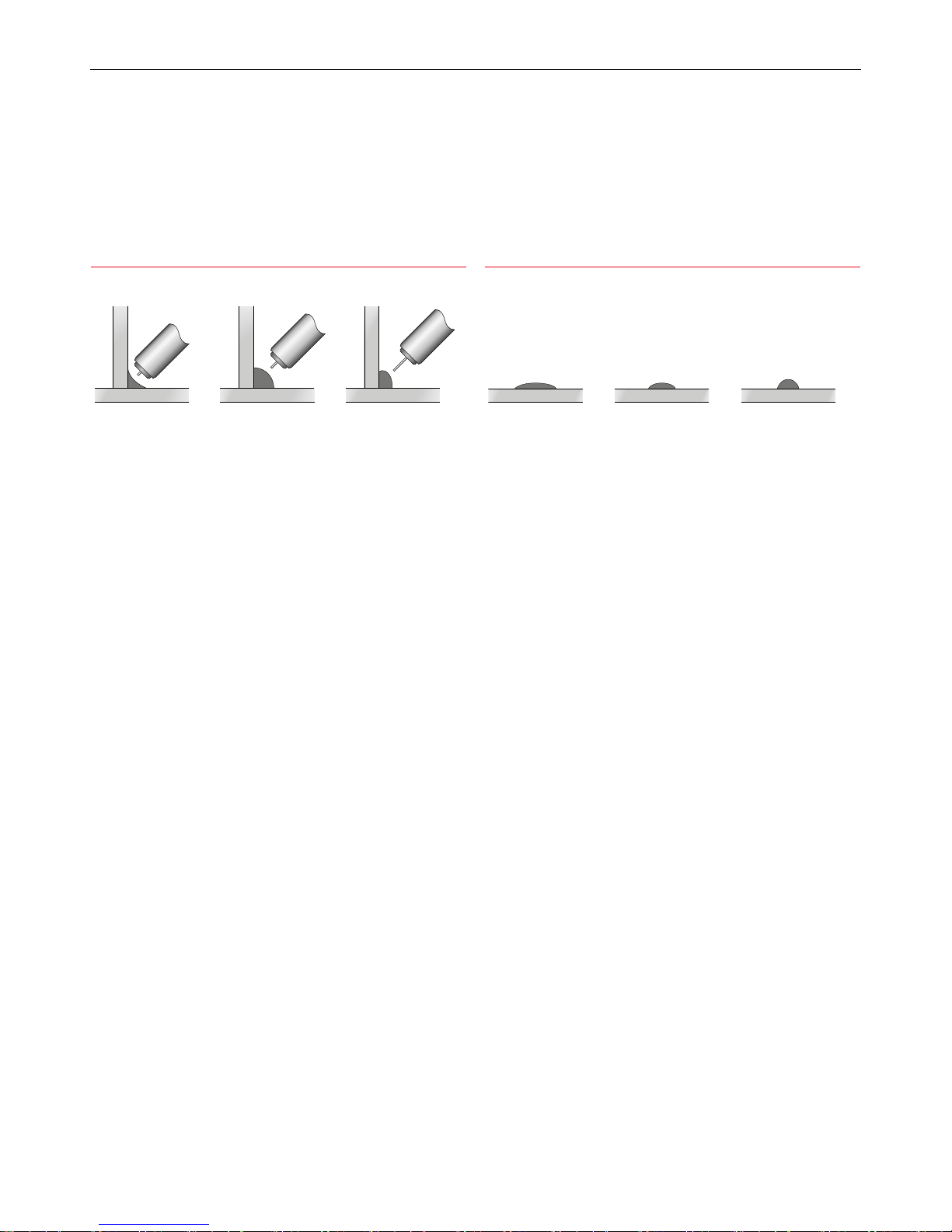
The electrical stickout is the distance between the end of the contact
tip and the end of the wire. An increase in the electrical stickout results
in an increase in the electrical resistance. The resultant increase in
temperature has a positive inuence in the melt-o rate of the wire that
will have an inuence on the weldbead prole.
Inuence of the change in electrical stickout length on the weldbead
prole.
The travel speed will have an inuence on the weldbead prole and the
reinforcement height.
If the travel speed is too slow a wide weldbead with excessive rollover
will result. Contrary if the travel speed is too high a narrow weldbead
with excessive reinforcement will result.
Recommendation about travel speed are contained in the detailed gases
datasheets found on pages 14-15 of this manual.
Electrical stickout
Short Normal Long
Travel speed
Slow Normal Fast
Page 27

27BOC Smootharc Advance II MIG 250C Operating manual
6.0 Package Contents
Package Contents
Power source with input cable
✓
MIG Torch Binzel MB 36KD
BOC Argon regulator
✓
Work return lead
✓
1× gas hose with quick release
✓
Wire feed rollers
Knurled 0.8-0.9/1.0-1.2
U Groove 0.8-0.9/1.0-1.2
V Groove 0.6-0.8/0.9-1.0/1.0-1.2
Toolbox
✓
Torch holder
✓
MMA Electrode holder
✓
Page 28
28
BOC Smootharc Advance II MIG 250C Operating manual
7.0 Installation
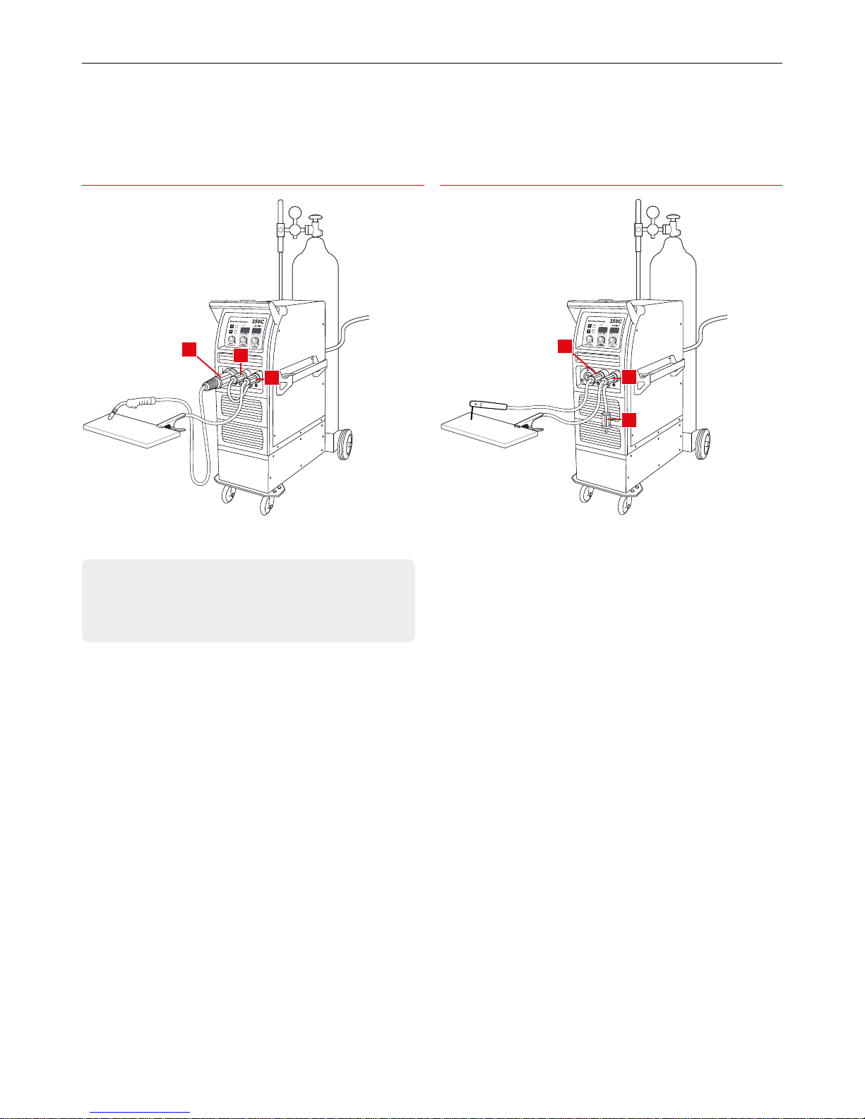
Installation for MIG/MAG process Installation for MMA process
IMPORTANT NOTICE
This machine requires a 32A, 250V, 3 pin plug to be tted by
acertied electrician.
7.1 Installation for MIG/MAG process
1 Connect the gas hose to the regulator and the rear of the machine.
Select correct shielding gas for the application.
2 Insert the earth return lead connection into the front panel.
3 Fit the wire spool to the machine. Select correct welding wire for
application.
4 Select the appropriate feed roller to suit the wire being used
- This machine comes complete with two types of wire feed rollers
- V groove for use with solid carbon manganese and stainless steels
- U groove for use with soft wires such as aluminium
5 Loosen the wire feed tension screws and insert the wire. Re t and
tension rollers ensuring the wire is gripped suciently so as not
to slip but avoid over tightening as this can aect feed quality and
cause wire feed components to wear rapidly.
6 Fit and tighten the torch on the output connection [A]. Ensure correct
torch liner and contact tip are selected.
7 Select the correct polarity for the type of wire used as indicated on
the consumable packaging. This is achieved by swapping the polarity
terminal wires. For most solid wires the terminal should be set as
torch positive.
8 For torch positive, plug the short mechanical connector (link plug) [B]
on the front panel into the positive (+) terminal and the work return
lead [C] into the negative (-) terminal.
9 For torch negative, couple the short mechanical connector [B] into
the terminal marked negative (-), and the work return lead [C] into
the positive (+) terminal.
7.2 Installation for MMA process
1 Connect the electrode holder [D] to the positive (+) of the machine
and fasten it clockwise tightly.
2 Connect the work return lead [C] into the negative (-) of the machine
and fasten it clockwise.
3 Please note that for manual metal arc (MMA) welding the electrode
holder can be switched to the negative pole of the welding machine
if so required by the specication of the electrode.
4 The short mechanical connector (link plug) [B] should remain
hangingfree.
Smootharc
AdvanceAdvance
II
250C
2T
4T
VOLTAGEINDUCTANCE
CRATER
ARC CURRENT
0 100 100 10
VA m/min
V
Smootharc
AdvanceAdvance
II
250C
2T
4T
VOLTAGEINDUCTANCE
CRATER
ARC CURRENT
0 100 100 10
VA m/min
V
A
B
C
D
B
C
Page 29
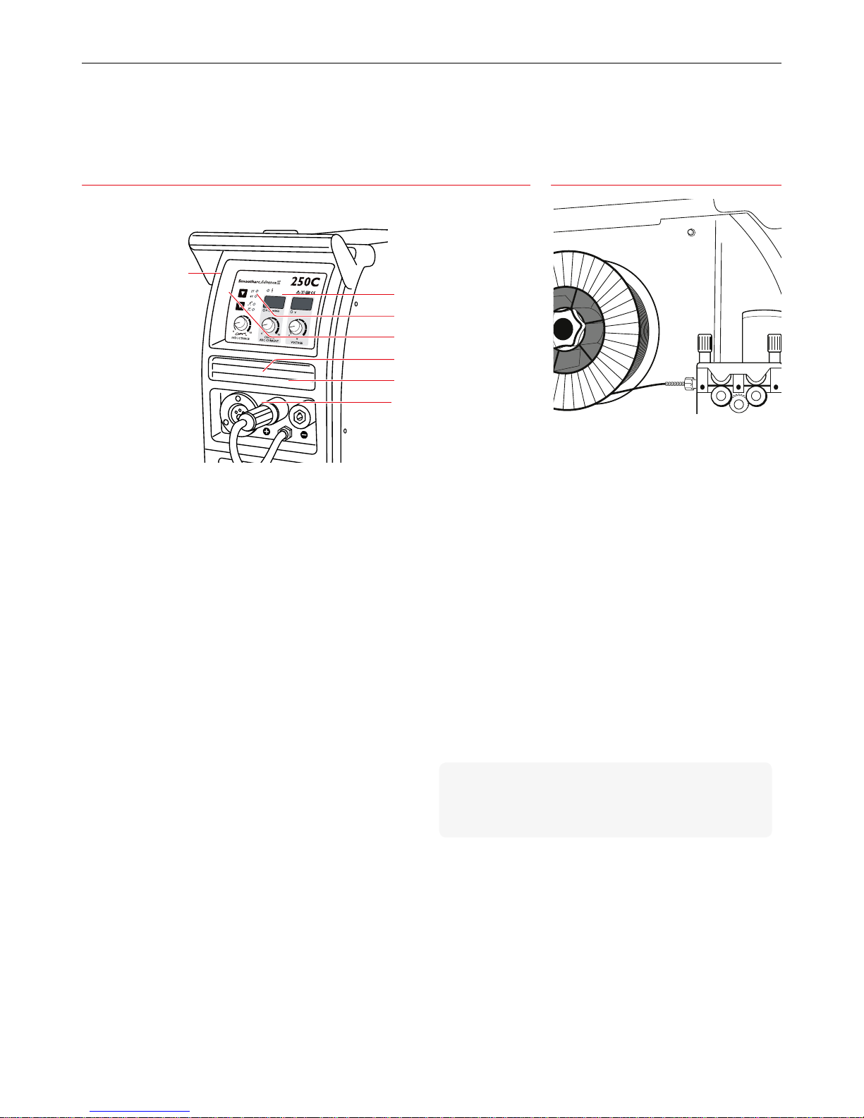
29BOC Smootharc Advance II MIG 250C Operating manual
6PRRWKDUF
$GYDQFH$GYDQFH
,,
&
7
7
92/7$*(,1'8&7$1&(
&5$7(5
$5&&855(17
9
$
PPLQ
9
8.1 MIG Welding Set-up
1 Ensure the machine is correctly plugged into the main circuit
2 Proper PPE must be worn
3 Ensure workplace safety such as fume extraction is in place
4 Switch machine on using On/O switch at the back of the machine
5 Open gas cylinder and set gas ow rate
6 Set voltage and wire feed speed (the tables included in this manual
can be used as a guideline for voltage and wire speed selection)
7 Voltage is set by adjusting voltage knob (1) on powersource
8 Wire feed speed can be set independently by adjusting the wire feed
speed/Arc current knob(2)
9 Inductance can be changed by adjusting the inductance knob (3) on
the power source
10 Welding wire can be fed through the torch by selecting “Wire Inch”
button located inside the power source above the wire feeder.
11 For certain types of self shielded ux cored wires it is required to
change the polarity. This can be achieved by switching the work
return lead and clamp from the negative dinse connector(5) to the
positive dinse connector (4). The pigtail needs to then change from
the positive dinse connector (4) to the negative dinse connector(5).
8.2 MMA Welding Set-up
1 Ensure the machine is correctly plugged into the main circuit
2 Proper PPE must be worn
3 Ensure workplace safety such as fume extraction is in place
4 Switch machine on using On/O switch at the back of the machine
5 Select process by depressing the process selection switch (7) toMMA
6 Fit work return lead to negative dinse*
7 Fit electrode holder to positive dinse connector*
8 Select Amperage by turning by wire feed speed/Arc current knob(2)
*
DCEP Connection. For DCEN when recommended by the
consumable supplier, reverse the terminals as stated in
points6 & 7.
8.0 Operation Set-up
Front of MIG 250C Inside of MIG 250C
2 Wire feed speed and Arc current
5 Negative dinse connector
1 Voltage
4 Positive dinse connector
7 Process selection switch
(MMA, MIG)
3 Inductance
6 Pigtail
Wire Inch
Page 30
30
BOC Smootharc Advance II MIG 250C Operating manual
Smootharc
AdvanceAdvance
II
250C
2T
4T
VOLTAGEINDUCTANCE
CRATER
ARC CURRENT
0 100 100 10
VA m/min
V
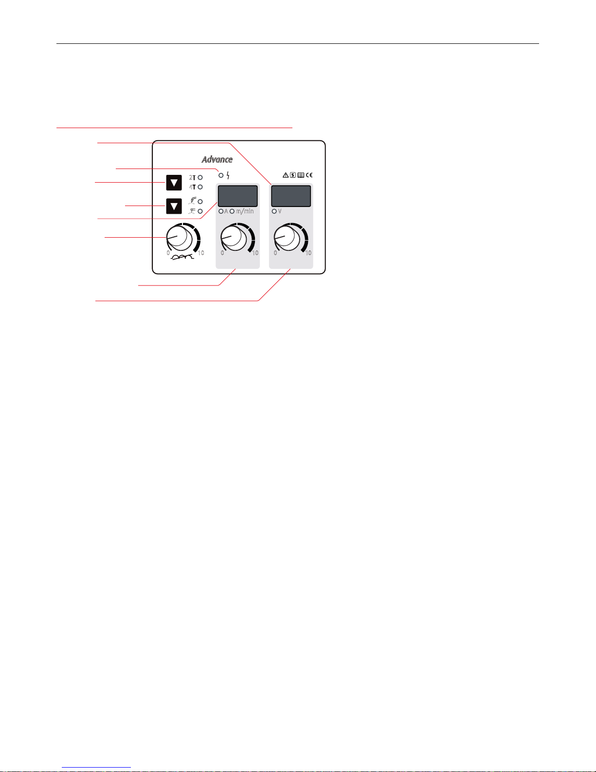
Current meter/
Wire speed meter
Control Panel of MIG 250C
9.1 Controls
The easy-to-operate and understand machine front panel includes two
LED displays for welding voltage and current/wire feed speed.
Torch latching
This is obtained by using the 2T/4T button on the machine front face.
Wire speed range adjustment
The wire speed is adjusted by turning the wire speed/Arc current knob
on the front panel.
Wire inch control
This control will feed the wire at a rate of 13m per minute through the
wire feeder without activating the gas solenoid of the power source
eliminating wastage of shielding gas.
By holding the wire inch button (located on the inside of the power
source) down it enables the operator to inch the wire through the torch
without having to depress the trigger.
This is also a safety feature because, if the operator uses the trigger on
the torch to feed the wire through, the welding current will also be on.
When the wire exits the torch it may make contact with the work piece
and cause an arc ash. This is injurious to exposed eyes and skin. It also
allows the wire to be feed through without the shielding.
Voltage adjustment
The inverter power source allows adjustment of welding voltage even
when the arc is struck.
Wire speed/Arc current
The wire feed control adjusts the speed that the wire is fed through the
MIG torch. The BOC Smootharc ADVANCE wire feed control is stepless
which means it can be adjusted whilst welding. This is an excellent
feature with these machines because the operator can set the ideal
parameters when welding. The higher the wire feed speed the higher
the amperage of the machine.
Inductance
Refer to section 9.2 for a complete explanation of the function of
inductance. Inductance on the BOC Smootharc ADVANCE machine can
beadjusted.
Changing the inductance will have an enhancing eect on both spatter
and weld bead appearance during dip transfer.
Adjusting the inductance modies the arc characteristics and is
particularly useful when using short circuiting (dip) to control
the amount of spatter produced. This is done by turning the
Inductanceknob.
Wire speed/Arc current knob
Voltage Knob
Process selection switch
Voltage meter
Power indicator light
2T/4T button
9.0 Control Panel
Inductance Knob
Page 31

31BOC Smootharc Advance II MIG 250C Operating manual
9.2 Inductance
Inductance is dened as the rise in current to above normal, in any
electrical circuit that results in the melting of the wire at some point.
Consider dip transfer (short ¬circuiting arc) in action. Before the wire
strikes the work-piece, there is no ow of current and the OCV has
maximum value. When the wire strikes the work-piece it creates what
is known as a “dead short”. This short-circuit causes the current to rise
rapidly and burn o the wire violently. This rapid melt ings about metal
globules as it takes place. These globules settle on the work-piece and
welding torch in the form of “spatter”.
To control the rise rate of short-circuiting current, a choke (or inductor) is
tted in series with the welding power cable. This inductor “chokes” the
rate of rise of current and ensures a smooth arc condition.
Inductance controls the rate of rise of short-circuiting current. It becomes
evident that inductance must be a function of time and current, since it
controls the time taken for the current to rise to the pre-set value. Hence
an increase in inductance results in less frequent short-circuiting. Fewer
short-circuits imply that the arc is present for a longer duration of time.
Increased “arc-on” time means increased heat.
Therefore, on a heavier plate where more heat is required to ensure
good fusion, more inductance would contribute immensely. Conversely
on thinner sections less inductance would lead to a decrease in “arc-on”
time, and consequently a “cooler” arc which enables thin materials to be
welded with ease.
Summarising, inductance has the following eects:
→ reduced spatter
→ heat control
→ has no eect when spray-arc welding, because there is no more
change in current, the inductance coil plays no further part. Acertain
amount of inductance with spray-transfer will provide softer starts
(the initial short-circuit)
9.3 4T/2T Trigger Latch Selection
On all MIG machines there is no current or wire feed until the trigger
on the torch is depressed. If a welder is doing a lot of welding then he/
she has to hold the trigger down for long periods of time and may cause
discomfort. This is can be similar to repetitive strain injury (RSI) that has
become a very popular topic for compensation by oce workers.
On all machines a special function called 2T and 4T is available. Also
referred to as trigger latching, this special feature allows the operator
to relax the trigger after rst depressing it and the gas shielding to
start before the welding commences. This feature is of particular
importance as it ensures that the weld will have adequate gas shielding
to eliminate the risk of oxidisation (contaminants) causing a defective
weld. (Remember, adefective weld may not be detected by a visual
inspection.)
The 2T/4T function also allows for the shielding gas to continue after the
weld has nished and cooled. This eliminates the risk of oxidation while
the weld is still in its molten state. This is particularly important when
welding stainless steel materials and aluminium.
Page 32

32
BOC Smootharc Advance II MIG 250C Operating manual
10.0 Troubleshooting and Fault Finding
Power source
Component Fault symptom Cause
Primary cable No or low welding output Bad or incorrect primary connection, lost phase
Earth cable and clamp Arc will not initiate Damaged, loose or undersized cables and clamps
Connectors and lugs Overheating of connectors andlugs Loose or badly crimped connectors
Switches Erratic or no output control Switches damaged or incorrectly set for the application
Wire feeder (as part of the powersource unit)
Component Fault symptom Cause
Gas solenoid valve No gas ow or gas ows continuously Gas valve faulty or sticking in open position
Wire feed rolls Wire slippage, wire deformation Incorrect feed roll size, incorrect tension adjustment,
misalignment
Inlet, outlet guides Wire shaving or snarling Incorrect wire guide sizes, misalignment
Universal adaptor Wire restriction, gas leaks, no trigger control Universal adaptor not correctly mounted or secured, incorrect
size of internal guide, bent contact pins
Wire feed speed control No control over wire feed speed, no amperage
control
Faulty wire speed feed potentiometer, wire feed motor in
overload or trip condition
Wire inch switch Wire live when feeding through cable and torch
before welding
Faulty wire inch switch, inappropriate use of torch trigger
switch
Spindle Wire spool drags or overruns Spindle brake set too tight or too loose, spool not properly
located on spindle
Welding torch
Component Fault symptom Cause
Type Welding torch overheats Welding torch underrated for welding application
Liners Erratic wire feed, wire snarls up at outlet guide Liner of incorrect type and size for wire in use, worn or dirty
liner, liner too long or too short
Gas distributor Inadequate gas ow, contaminated or porous weld Damaged or blocked distributor
Nozzle Inadequate gas cover, restricted joint accessibility Nozzle too large or too small, incorrect length or shape
Contact tip Erratic feeding, wire shudder, wire burnback,
unstable arc, spatter
Incorrect size of contact tip, incorrect contact tip to nozzle
distance for metal transfer mode, inferior contact tip material
Nozzle insulator Arcing between contact tip and nozzle and
between nozzle and workpiece
No nozzle insulator tted
Regulator / owmeter
Component Fault symptom Cause
Inlet stem No gas ow, gas leaks at regulator body or
cylindervalve
Blocked inlet stem, leaking inlet stem to body thread, bullnose
not properly seated in cylinder case
Gas hose and tting Leaks at connections or in the hose, porosity in
theweld
Poorly tted ‘o’ clips, damaged hose, air drawn into gas stream
Shielding gas
Component Fault symptom Cause
Cylinder, MCPs No gas ow, porosity in the weld Gas cylinder closed or empty, faulty cylinder valves
Bulk No gas ow, change in welding conditions Bulk tank empty, incorrectly set mixing panel
Welding wire
Component Fault symptom Cause
Wire basket and spool Erratic wire feeding or wire stoppages Damaged wire basket, loose spooling, random-wound wire
Wire Wire sticks in contact tip, erratic feeding Varying wire diameter, copper aking, surface damage
Wire Weld has excessive amount of spatter Wrong polarity has been selected
Page 33

33BOC Smootharc Advance II MIG 250C Operating manual
11.0 Replacement Parts
MIG 250C Suitability Description Part No.
Torch
✓
Binzel MB Grip 36KD Air Cooled 3m 014.0234
Wire Feed Rollers
✓
Self-Shielded Flux Cored Knurled 0.8–0.9 ADVANCEKNROL0809
✓
Knurled 1.0–1.2 ADVANCEKNROL1012
Knurled 1.2–1.6 ADVANCEKNROL1216
✓
Aluminium U Groove 0.8–0.9 ADVANCEUROL0809
✓
U Groove 1.0–1.2 ADVANCEUROL1012
U Groove 1.2–1.6 ADVANCEUROL1216
✓
Steel, Stainless Steel V Groove 0.6–0.8 ADVANCEVROL0608
✓
V Groove 0.9–1.0 ADVANCEVROL0910
✓
V Groove 1.0–1.2 ADVANCEVROL1012
Page 34

34
BOC Smootharc Advance II MIG 250C Operating manual
12.0 Periodic Maintenance
The working environment or amount of use the machine receives should
be taken into consideration when planning maintenance frequency of
your MIG 250C welder.
Preventative maintenance will ensure trouble-free welding and increase
the life of the machine and its consumables.
12.1 Power Source
• Check electrical connections of unit at least twice a year.
• Clean oxidised connections and tighten.
• Inner parts of machine should be cleaned
with a vacuum cleaner and soft brush.
• Do not use any pressure-washing devices.
• Do not use compressed air as pressure may pack dirt even more tightly
into components.
• Only authorised electricians should carry
out repairs and internal servicing.
Page 35

35BOC Smootharc Advance II MIG 250C Operating manual
13.0 Technical Specications
Specications MIG/MAG MMA
Part No. ADVANCE II 250C
Power voltage Single phase 240 V ±15 %
Frequency 50/60 Hz
Rated input current (Ie) 32A
Output current 50 A to 250 A 50 A to 220 A
Output Voltage 16.5 V to 26.5 V 22 V to 28.8 V
Duty cycle
30 % – 220
35 % 250 –
60 % 200 180
Power factor 0.73
Eciency 80 %
Wire speed 2.5 to 13 (m/min)
Wire spool diameter 270 mm
Wire diameter 0.8/1.2 mm
Housing shielding grade IP21
Insulation grade F
Suitable thickness 0.8 mm above
Dimensions L × W × H 1075 × 418 × 795 mm
Weight approx. 45 kg (Power source)
Wire feeder Built in
Standards IEC60974.1
Page 36

36
BOC Smootharc Advance II MIG 250C Operating manual
14.0 Warranty Information
14.1 Terms of Warranty
The Smootharc ADVANCE II machine has a limited warranty that covers
manufacturing and material defects only. The warranty is aected on the
day of purchase and does not cover any freight, packaging and insurance
costs. Verbal promises that do not comply with terms of warranty are not
binding on warrantor.
14.2 Limitations on Warranty
The following conditions are not covered under terms of warranty: loss or
damage due to or resulting from natural wear and tear, non-compliance
with operating and maintenance instructions, connection to incorrect
or faulty voltage supply (including voltage surges outside equipment
specs), incorrect gas pressure overloading, transport or storage damage
or re or damage due to natural causes (e.g. lightning or ood). This
warranty does not cover direct or indirect expenses, loss, damage of
costs including, but not limited to, daily allowances or accommodation
and travelling costs.
NOTE
Under the terms of warranty, welding torches and their consumables,
feed, drive rollers and feeder guide tubes are not covered. Direct or
indirect damage due to a defective product is not covered under the
warranty. The warranty is void if changes are made to the product
without approval of the manufacturer, or if repairs are carried out using
non-approved spare parts. The warranty is void if a non-authorised
agent carries outrepairs.
14.3 Warranty Period
The warranty is valid for 3 years from date of purchase provided the
machine is used within the published specication limits.
14.4 Warranty Repairs
Your service provider must be informed within the warranty period
of any warranty defect. The customer must provide proof of purchase
and serial number of the equipment when making a warranty claim.
Warranty repairs may only be carried out by approved BOC service
providers. Please contact your local BOC Gas & Gear for a directory of BOC
approved service providers in your area.
Page 37

37BOC Smootharc Advance II MIG 250C Operating manual
Page 38

38
BOC Smootharc Advance II MIG 250C Operating manual
Page 39

Page 40

MP14-0234 . FDAUS . 0715
© BOC Limited 2015. BOC is a trading name of BOC Limited, a Member of The Linde Group. Reproduction without permission is strictly prohibited. Details given in this document are
believed to be correct at the time of printing. Whilst proper care has been taken in the preparation, no liability for injury or damage resulting from its improper use can be accepted.
BOC Limited ABN 95 000 029 729
10 Julius Avenue, North Ryde NSW 2113, Australia
BOC Limited WN007748
970–988 Great South Road, Penrose, Auckland, New Zealand
For more information contact the BOC Customer Service Centre.
BOC Australia
131 262
www.boc.com.au
BOC New Zealand
0800 111 333
www.boc.co.nz
 Loading...