


SAM 935
Table of contents
 Loading...
™
SAM 935
Surveillance and Measurement System
Instruction Manual
Berkeley Nucleonics Corporations
3060 Kerner Boulevard #2
San Rafael, CA 94901 USA
800-234-7858
415-453-9955
fax: 415-453-9956
http:/www.berkeleynucleonics.com

Firmware Release 02.05.19
U. S. Patent No. 5608222
© 1995-1999 All rights reserved.
Printed in U.S.A. - 03/30/00
WARRANTY
Berkeley Nucleonics Corporation warrants all instruments, including component parts, to be free from defects in material and
workmanship, under normal use and service for a period of one year. If repairs are required during the warranty period, contact the
factory for component replacement or shipping instructions. Include the serial number of the instrument. This warranty is void if the
unit is repaired or altered by others than those authorized by Berkeley Nucleonics Corporation.
IMPORTANT!! PLEASE READ CAREFULLY
NOTIFICATION OF COPYRIGHT
THE FIRMWARE IN THIS DEVICE IS PROTECTED BY COPYRIGHT LAWS AND INTERNATIONAL TREATY. YOU MUST TREAT
THE FIRMWARE LIKE ANY OTHER COPYRIGHTED MATERIAL. COPYRIGHT LAWS PROHIBIT MAKING ADDITIONAL COPIES
OF THE FIRMWARE FOR ANY REASON OTHER THAN SPECIFICALLY DESCRIBED IN THE LICENSE BELOW. YOU MAY NOT
COPY THE WRITTEN MATERIALS ACCOMPANYING THE PRODUCT.
2 SAM 935™ Instruction Manual

Table of Contents
1 Introduction . . . . . . . . . . . . . . . . . . . . . . . . . . . . . . . . .1
1.1 How To Use This Manual . . . . . . . . . . . . . . . . . . . . . . . . . . . . . . 1
1.2 Quick Reference . . . . . . . . . . . . . . . . . . . . . . . . . . . . . . . . . . . 3
1.2.1 Power On the SAM 935 . . . . . . . . . . . . . . . . . . . . . . . . . . 3
1.2.2 Quick Calibration and Background Reading . . . . . . . . . . . . . . . . 3
1.2.3 Take Samples and Review Alarms. . . . . . . . . . . . . . . . . . . . . 5
2 Connecting Hardware . . . . . . . . . . . . . . . . . . . . . . . . . . . .6
2.1 Connecting Power . . . . . . . . . . . . . . . . . . . . . . . . . . . . . . . . . . 6
2.2 Connecting to a Printer . . . . . . . . . . . . . . . . . . . . . . . . . . . . . . . . 6
2.3 Connecting to a Remote Computer . . . . . . . . . . . . . . . . . . . . . . . . . 7
2.4 Connecting an Optional External Detector . . . . . . . . . . . . . . . . . . . . . . 7
3 Configuring the SAM 935 . . . . . . . . . . . . . . . . . . . . . . . . . .8
3.1 Starting Up the SAM 935 . . . . . . . . . . . . . . . . . . . . . . . . . . . . . . . 8
3.2 Recalibration Procedure . . . . . . . . . . . . . . . . . . . . . . . . . . . . . . 10
3.2.1 Automatic Coarse Calibration . . . . . . . . . . . . . . . . . . . . . . 11
3.2.2 Acquire a Background Spectrum . . . . . . . . . . . . . . . . . . . . . 12
3.2.3 Fine Energy Calibration. . . . . . . . . . . . . . . . . . . . . . . . . . 14
3.2.4 Calibration with Three Coefficients . . . . . . . . . . . . . . . . . . . . 17
3.3 Configure Dose Rate Units and Trigger . . . . . . . . . . . . . . . . . . . . . . 17
3.4 Dose Rate Calibration . . . . . . . . . . . . . . . . . . . . . . . . . . . . . . . 19
4 Operating the SAM 935 . . . . . . . . . . . . . . . . . . . . . . . . . . 20
4.1 Recommended Daily Operating Procedure . . . . . . . . . . . . . . . . . . . . 20
4.2 Powering the SAM 935 On . . . . . . . . . . . . . . . . . . . . . . . . . . . . . 20
4.2.1 Quick Calibration Adjustment. . . . . . . . . . . . . . . . . . . . . . . 22
4.3 Powering the SAM 935 Off . . . . . . . . . . . . . . . . . . . . . . . . . . . . . 23
4.4 Taking Readings in Surveillance Mode . . . . . . . . . . . . . . . . . . . . . . 24
4.5 Reviewing Alarms . . . . . . . . . . . . . . . . . . . . . . . . . . . . . . . . . 25
4.6 The SAM 935 Interface . . . . . . . . . . . . . . . . . . . . . . . . . . . . . . . 26
4.6.1 The Front Panel . . . . . . . . . . . . . . . . . . . . . . . . . . . . . 26
4.6.2 Function Keys . . . . . . . . . . . . . . . . . . . . . . . . . . . . . . 27
4.6.3 Scrolling Through Long Menus. . . . . . . . . . . . . . . . . . . . . . 27
4.6.4 Editing Instructions . . . . . . . . . . . . . . . . . . . . . . . . . . . . 27
4.6.5 The Utilities Screen. . . . . . . . . . . . . . . . . . . . . . . . . . . . 29
5 SAM 935 Modes of Operation . . . . . . . . . . . . . . . . . . . . . . 30
5.1 The Surveillance Mode of Operation . . . . . . . . . . . . . . . . . . . . . . . . 30
5.2 The Monitor Mode of Operation . . . . . . . . . . . . . . . . . . . . . . . . . . 31
5.3 The Detail Mode of Operation . . . . . . . . . . . . . . . . . . . . . . . . . . . 32
5.4 Manual Mode . . . . . . . . . . . . . . . . . . . . . . . . . . . . . . . . . . . . 32
5.4.1 MCA Presets . . . . . . . . . . . . . . . . . . . . . . . . . . . . . . . 34
5.4.2 Manual Hardware Adjustments. . . . . . . . . . . . . . . . . . . . . . 35
5.4.3 Manual Mode Utilities. . . . . . . . . . . . . . . . . . . . . . . . . . . 36
5.5 Background Mode . . . . . . . . . . . . . . . . . . . . . . . . . . . . . . . . . 37
SAM 935™ Instruction Manual 1

5.6 Calibration Mode . . . . . . . . . . . . . . . . . . . . . . . . . . . . . . . . . . 38
5.6.1 Manual Coarse Adjust with Cs137 . . . . . . . . . . . . . . . . . . . . 38
5.6.2 Fine Energy Calibration . . . . . . . . . . . . . . . . . . . . . . . . . . 39
6 Utilities . . . . . . . . . . . . . . . . . . . . . . . . . . . . . . . . . . 40
6.1 Area Monitor Setup . . . . . . . . . . . . . . . . . . . . . . . . . . . . . . . . . 41
6.1.1 Set the Sample Time . . . . . . . . . . . . . . . . . . . . . . . . . . . 41
6.1.2 Select Triggers . . . . . . . . . . . . . . . . . . . . . . . . . . . . . . 42
6.1.3 Set the Default Trigger Levels . . . . . . . . . . . . . . . . . . . . . . 43
6.1.4 Preventing False Alarms . . . . . . . . . . . . . . . . . . . . . . . . . 44
6.1.5 Calibrate Dose Rate. . . . . . . . . . . . . . . . . . . . . . . . . . . . 45
6.1.6 Configure Alarm Hardware . . . . . . . . . . . . . . . . . . . . . . . . 47
6.2 Clear Stored Alarms . . . . . . . . . . . . . . . . . . . . . . . . . . . . . . . . 47
6.3 Edit Isotopes . . . . . . . . . . . . . . . . . . . . . . . . . . . . . . . . . . . . 47
6.3.1 Adding a New Isotope. . . . . . . . . . . . . . . . . . . . . . . . . . . 48
6.3.2 Enable/Disable Isotopes . . . . . . . . . . . . . . . . . . . . . . . . . 48
6.3.3 Editing an Isotope . . . . . . . . . . . . . . . . . . . . . . . . . . . . . 48
6.4 Edit Isotope Radiations . . . . . . . . . . . . . . . . . . . . . . . . . . . . . . . 49
6.5 Print Databases . . . . . . . . . . . . . . . . . . . . . . . . . . . . . . . . . . . 49
6.6 Edit Calibration Standards . . . . . . . . . . . . . . . . . . . . . . . . . . . . . 50
6.6.1 Adding a Standard . . . . . . . . . . . . . . . . . . . . . . . . . . . . 50
6.6.2 Deleting a Standard . . . . . . . . . . . . . . . . . . . . . . . . . . . . 50
6.6.3 Editing a Standard . . . . . . . . . . . . . . . . . . . . . . . . . . . . 50
6.7 Select / Edit Detector . . . . . . . . . . . . . . . . . . . . . . . . . . . . . . . . 51
6.8 Analysis Tools Setup . . . . . . . . . . . . . . . . . . . . . . . . . . . . . . . . 52
6.9 Select Spectrum Draw Style . . . . . . . . . . . . . . . . . . . . . . . . . . . . 53
6.10 Show System Information . . . . . . . . . . . . . . . . . . . . . . . . . . . . . . 53
6.11 Set Serial Speed . . . . . . . . . . . . . . . . . . . . . . . . . . . . . . . . . . 54
6.12 Set Report Title String . . . . . . . . . . . . . . . . . . . . . . . . . . . . . . . 54
6.13 Set System Clock—Date and Time . . . . . . . . . . . . . . . . . . . . . . . . . 54
6.14 Set Backlight Delay Time . . . . . . . . . . . . . . . . . . . . . . . . . . . . . . 55
6.15 Print Stored Spectra . . . . . . . . . . . . . . . . . . . . . . . . . . . . . . . . 55
6.16 Clear Stored Spectra . . . . . . . . . . . . . . . . . . . . . . . . . . . . . . . . 55
6.17 Switch to Remote . . . . . . . . . . . . . . . . . . . . . . . . . . . . . . . . . . 56
6.18 Clear ALL Data and Reset . . . . . . . . . . . . . . . . . . . . . . . . . . . . . 56
7 Reports . . . . . . . . . . . . . . . . . . . . . . . . . . . . . . . . . . 57
7.1 Area Monitor Report of Alarms . . . . . . . . . . . . . . . . . . . . . . . . . . . 57
7.2 Background Report . . . . . . . . . . . . . . . . . . . . . . . . . . . . . . . . . 57
7.3 Energy Calibration Report . . . . . . . . . . . . . . . . . . . . . . . . . . . . . 58
7.4 Manual MCA Report . . . . . . . . . . . . . . . . . . . . . . . . . . . . . . . . 59
7.5 Database Reports . . . . . . . . . . . . . . . . . . . . . . . . . . . . . . . . . . 60
8 Specifications . . . . . . . . . . . . . . . . . . . . . . . . . . . . . . 61
Appendix A: AutoLoad . . . . . . . . . . . . . . . . . . . . . . . . . . . 63
A.1 Installing AutoLoad . . . . . . . . . . . . . . . . . . . . . . . . . . . . . . . . . 63
A.2 Using AutoLoad . . . . . . . . . . . . . . . . . . . . . . . . . . . . . . . . . . . 63
A.3 Device-Specific Notes for the SAM 935 . . . . . . . . . . . . . . . . . . . . . . . 65
2 SAM 935™ Instruction Manual

1. Introduction
Welcome to the SAM 935™, a portable surveillance and measurement system for detecting and identifying
multiple nuclides.The SAM 935 identifies mixed isotopes, providing quantified results and time-slice
analysis.
The SAM 935 has a large feature set that addresses almost any gamma radiological task. It can be used in
a very simple mode that does not require any radiological experience. The purpose of the Quick Reference
in Section 1.2 is to give the operator the information needed to use the SAM 935 for radiation detection
and isotopic identification. Complete discussions of the full SAM 935 functionality can be found in the
remainder of the manual.
The modes of operation are described in Section 5. The SAM 935 is not just a MCA since it has many
automated and easy-to-use features with real time analysis. Therefore, operation solely from the Manual
mode does not use the intelligence that makes the SAM a very unique instrument. The operator should be
aware that the SAM 935 is designed to be operated primarily in the Surveillance, Monitor, or Detail mode.
In any of these modes an alarm may be stored, reviewed, and dragged into the manual MCA for further
analysis. This not only makes for ease of operation but allows greater functionality and immediate identification of isotopes. Furthermore, these primary modes of operation allow review and printout of each stored
alarm. The Manual mode will not allow review of stored events, dose-rate measurements, neutron measurements, or many of the time slice features built into this instrument.
QuantumMCA and QuantumGold are PC software packages that allow up to 8 MCAs to be controlled at
one time with up to 16K of real time display. QuantumMCA is the standard software and QuantumGold is
the premier software for quantitative analysis. These packages are available with their own documentation
on operation. Appendix A of this manual gives instructions for loading the PC software (see also Section
6.17 for remote access). This software will allow analysis in 256 QCC or linear, 512 QCC or linear, and
1024 linear modes. When using the SAM 935 without a PC, operation is limited to 256 and 512 QCC. However, all stored data (including 1024 linear that is not stored) may be transferred from the SAM to the PC
for analysis.
1.1 How To Use This Manual
This manual uses the following typographic conventions:
File Menu names are shown in bold mixed case, indicating the SAM 935
screen mode.
E
NTER, F1…F4 Small capital letters are used for the names of keys to be pressed on the
SAM 935.
Calibrate Area Monitor
SAM 935™ Instruction Manual 1
Choices in menu listings and on-screen prompts are shown in italics.

This page intentionally blank.
2 SAM 935™ Instruction Manual
1.2 Quick Reference
Operating the SAM 935 is a simple 3-step process:
1. Power on the SAM 935.
2. If prompted to do so, take a quick calibration and background reading.
3. Take samples and review any alarms.
1.2.1 Power On the SAM 935
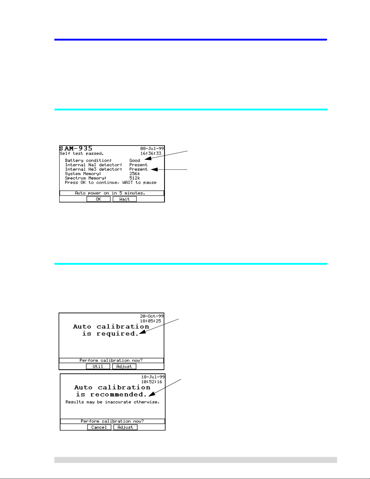
When you power on the SAM 935, it will first run a self-test as shown below:
Note the battery condition here.
Note the type of detector(s) installed here.
After the self-test has run, the SAM 935 will proceed to auto-start after 5 minutes have elapsed, after which
you can begin operating the unit.
Y ou can also press OK (F2) to immediately start up. Press W
AIT (F3) to delay startup for another 5 minutes.
If you are not prompted to take a calibration, you can proceed to take readings; skip to Section 1.2.3.
1.2.2 Quick Calibration and Background Reading
After the self-test, the SAM 935 may detect that a calibration and background reading are needed. If it
does, you will see one of the two prompts shown below. Until you perform the adjustment, these messages
will show up every time the SAM 935 is powered on.
“Calibration required” means this is the first time the SAM
935 has been powered up, or some important setting
changed that requires calibration. Note that your two
choices are to perform the cal ibration adj ustment (F3) or to
enter the Utilities menu to adjust the instrument settings
(F2).
The “calibration recommended” prompt appears when a
calibration has not been performed in over a week. Note
that your two choices are to perform the calibration adjustment (F3) or to continue with st artup witho ut perfor ming the
calibration (F2). If you choose to skip the calibration, the
monitoring results may not be reliable.
SAM 935™ Instruction Manual 3
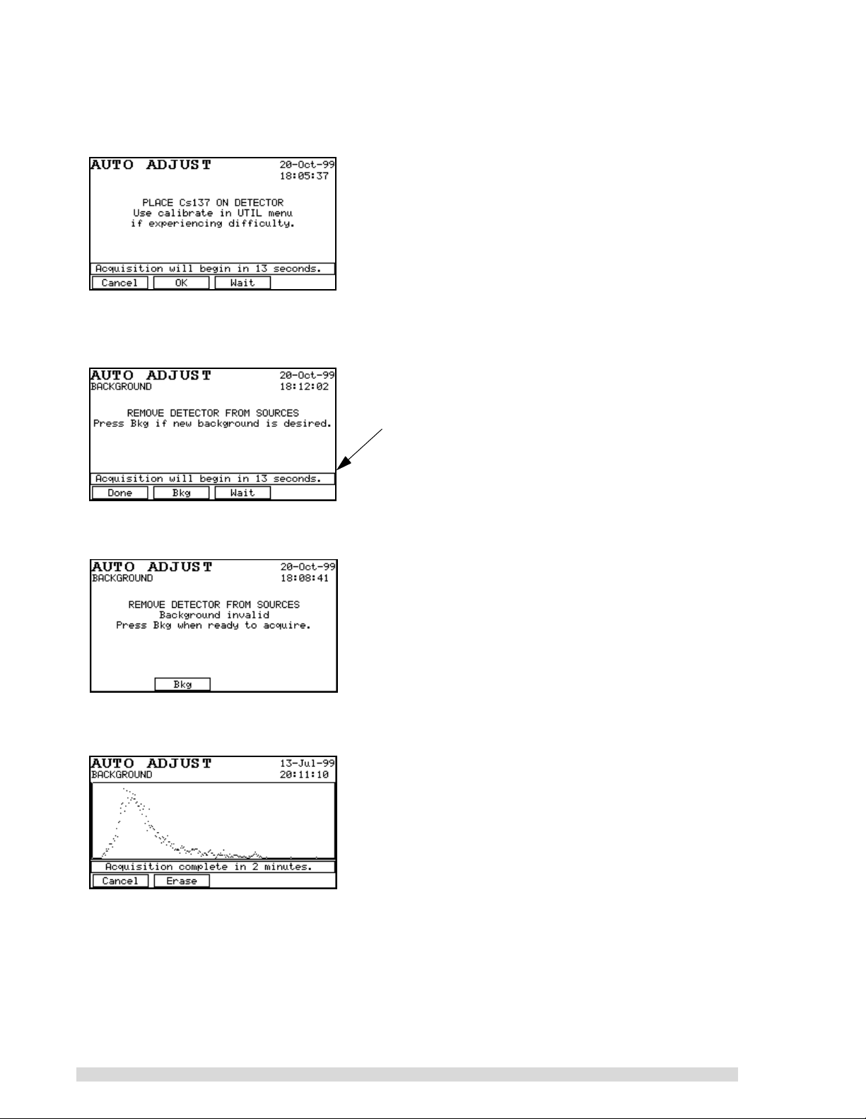
1. Press the ADJUST (F3) button.
2. You will be prompted to place the Cs137 standard in front of the detector. Position the standard as
closely as possible to the right front corner of the SAM 935, where the internal detector resides:
3. After the SAM 935 has finished its coarse calibration, it will beep two times and give you the opportunity to take a background spectrum. Remove the Cs137 source from the vicinity of the detector
and press B
KG (F2) to begin taking the background reading:
If you do not take a background reading, the SAM 935 will
enter its monitoring mode after a preset 15-second delay.
Press Wait (F3) to restart the 15-second countdown if you
need more time to remove the source.
If the SAM 935 detects that the background reading is unusable or non-existent, it will present this
screen that requires you to take a background reading:
4. The automatic background adjustment will take 1 minute (the factory setting). You will see the
spectrum resolve on screen as it is acquired:
5. The SAM 935 may recommend a fine calibration at this point, if the external detector was changed
or if the fine calibration has been corrupted (refer to Section 3.2.3). Normally, however, only the
coarse adjustment and background reading are required.
6. When the calibration adjustments are done, the dose rate monitoring screen will appear and you
can begin taking samples.
For more information on quick calibration, refer to Section 4.2.1.
4 SAM 935™ Instruction Manual
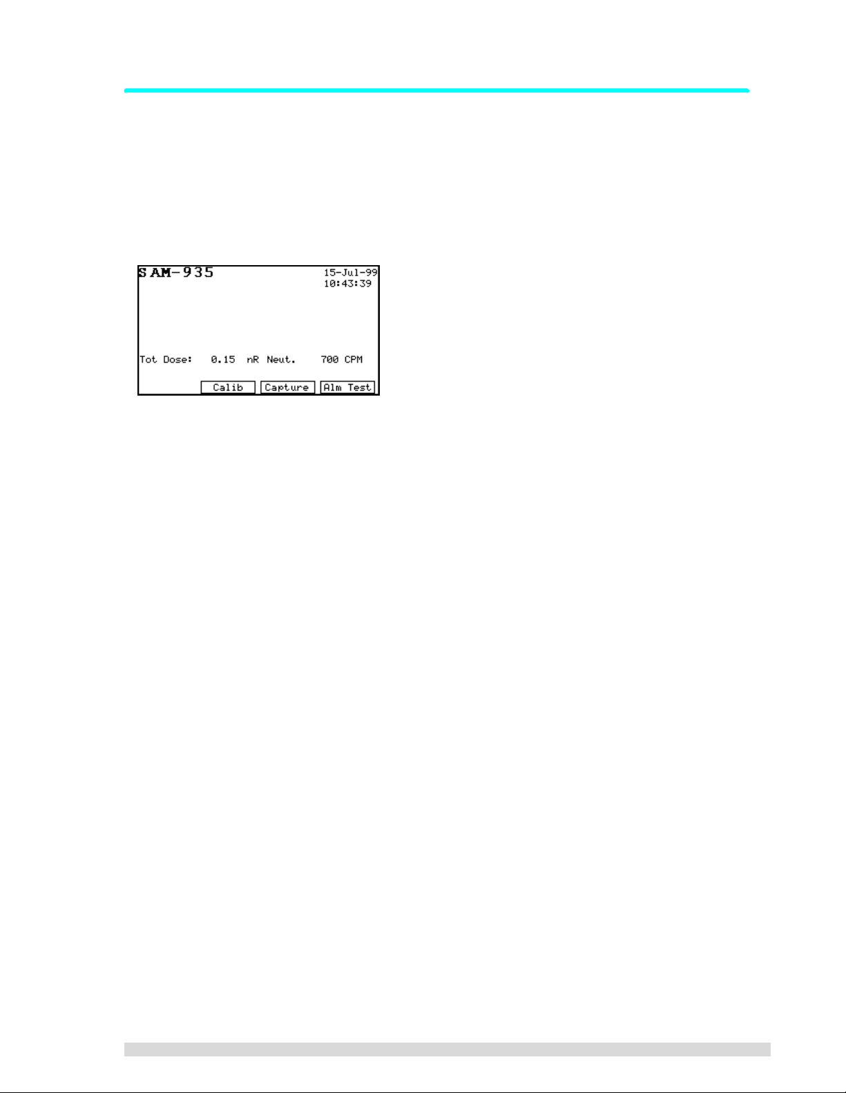
1.2.3 Take Samples and Review Alarms
The monitoring display of the SAM 935 will look different depending on the operating mode of the instrument. The default operating mode for the SAM 935 is Surveillance mode, also called dose rate monitoring.
In Surveillance mode, the SAM 935 continuously takes readings and analyzes isotopes in dose rate units,
saving and reporting any alarm conditions (when the dose rate exceeds the dose rate trigger).
The dose rate monitoring screen will look something like this (depending on how the SAM 935 was
configured):
1. Hold the SAM 935 in front of you so you can read the display.
2. Take readings by pointing the right front corner of the detector at the sample, as closely as possible. (The internal detector is installed on the right side of the SAM 935. If using the
factory-supplied, optional external detector, position the detector and sample in close proximity to
each other.) The SAM 935 will take continuous readings.
3. To manually save a reading or alarm, press C
alarm, if any, will be terminated when you press C
APTURE (F3) to save the current display. The current
APTURE. If the condition continues to alarm, a
new alarm will be created and you will again have the choice to capture it or not.
4. To review alarms, use the right and left arrow buttons. Use the right arrow button to review the
alarms in order they were taken (newest to oldest). Use the left arrow button to review alarms in
reverse order (oldest to newest).
SAM 935™ Instruction Manual 5

2. Connecting Hardware
This chapter describes how to connect optional, peripheral devices to the SAM 935. The SAM 935 consists
of the spectrometer electronics, internal detector(s), and optionally, an external detector. Simply follow the
instructions below for connecting a printer or personal computer, and if purchased, the optional external
detector.
There are two tubes on each end of the SAM 935; the left tube (if you are holding the SAM 935 in normal
operating mode) holds the battery pack. The right tube holds the internal detector. The optional internal
neutron detector is installed along the front edge of the SAM 935.
The connection ports for the analog power cord and peripheral devices are located on the front left side of
the SAM 935 (when holding the unit in normal operating mode), next to the battery pack tube. Slide the
cover back to reveal the ports.
An RS-232 serial connector (DB9M), above the power port, is used to connect the SAM 935 to a printer or
to a host computer; see Sections 2.2 and 2.3 for more information.
2.1 Connecting Power
The SAM 935 operates off of an internal battery pack, which is located in the left tube (if you are holding
the unit in normal operating mode).
To guarantee good results, recharge the SAM 935’s battery pack when you first receive the unit from the
factory. Thereafter, the clock on the top panel display will be replaced with a
the battery pack needs to be recharged or replaced.
1. To recharge the battery pack, simply plug the factory-supplied battery charger in to the power port
on the front panel (holding the unit in normal operating mode). The power port is located below the
RS-232 port and next to the power on/off button.
2. Plug the other end into a standard wall outlet. It will take approximately 4 hours to recharge a completely empty battery pack. The batteries will recharge only if the SAM 935 is turned off during this
time.
Always use the factory-supplied battery charger to ensure that the batteries are not damaged.
3. The SAM 935 can be operated continuously from the battery charger; however, it cannot simultaneously be powered on and recharge the internal battery pack.
4. The SAM 935's power switch is the push button next to the power port.
Battery Low
message when
2.2 Connecting to a Printer
The SAM 935 may be connected to a printer for printing a variety of reports. If you purchased a preconfigured printer from BNC, simply attach the printer to the serial port on the front panel of the SAM 935,
located above the power on/off switch, and it is ready for use.
If you are using another printer, follow the instructions in the rest of this section:
6 SAM 935™ Instruction Manual

Most printers compatible with the Epson command set (9-pin,
24-pin, and ink jet printers) are supported. If your printer does not
have an option for a serial port connection, you may need to purchase an RS-232 serial to Centronics parallel adapter (available as
an option from BNC). Otherwise, the printer may be attached to the
SAM 935 in exactly the same fashion as you would attach it to the
serial port of any computer.
Set the printer serial configuration to 19,200 baud (or another baud
rate if you have changed the SAM 935 defaults), 8 data bits, 1 start
bit, 1 stop bit, no parity. It is also important, if your printer has this
feature, to set the font to the Latin1/European font rather than the
italic font so that special characters will be printed correctly. See
SAM 935 RS-232 Connections
Power
Receive Data
Transmit Data
No Connection
Ground
No Connection
Request to Send
Clear to Send
No Connection
VCC
RX
TX
GND
TRS
CTS
1
2
3
4
5
6
7
8
9
your printer manual for details.
After starting up the SAM 935, set the serial speed to match the printer’s in the SAM 935 Utilities menu;
see Section 6.11.
2.3 Connecting to a Remote Computer
The SAM 935 may be connected to a remote computer running the PGT QUANTUM MCA® software. The
Quantum software comes with AutoLoad, a program for uploading spectra saved in SAM 935 to a personal
computer. The installation and use of this program is covered in Appendix A: AutoLoad.
To make the hardware connection between the SAM 935 and the personal computer, a null modem cable
is required. The SAM 935 may be connected to any serial port of the host computer, provided that this
serial port is accessible from Microsoft Windows
®
.
1. Simply align the connector on one end of the cable with the 9-pin serial connector on the SAM 935
(RS-232), and press to insert.
2. Repeat with the connector on the host computer.
3. After starting up the SAM 935, set the serial speed to match the printer’s in the SAM 935 Utilities
menu; see Section 6.11.
4. In the hardware search program, select the baud rate and COM port to which the SAM 935 is
attached.
5. On the SAM 935, press the U
6. Press the U
PDATE button. The Quantum hardware search software should automatically detect the
SAM 935 when you press the U
TIL key. Select REMOTE (F4).
PDATE button in its MCA Devices Auto Configuration window.
2.4 Connecting an Optional External Detector
If you purchased an optional external detector with the SAM 935, attach the supplied LEMO connector to
the port on the right-hand side of the SAM 935 (holding the unit in normal operating mode). The other end
of the LEMO connector attaches to the external detector.
SAM 935™ Instruction Manual 7
3. Configuring the SAM 935
This chapter describes in detail how to set up the SAM 935 for daily operation. Most of the setup takes
place in the Utilities menu.
Summary of Steps to Take:
1. Connect the hardware as described in the previous section.
2. Power on the SAM 935 and let it self-test and start up.
3. Perform a recalibration of the SAM 935: (a) a coarse adjustment, (b) a background spectrum, and
if using a new detector, (c) a fine energy calibration. T o complete all three calibration steps, you will
need a Cs137 source and an Eu152 source.
N
OTE: When you first install the SAM 935 and whenever the temperature changes drastically, you must
perform a coarse adjustment with Cs137 and a background spectrum. You MUST
with both sources (including a fine energy calibration) if you change the detector.
4. Configure the dose rate units of measurement and alarm trigger.
5. Configure any other settings found in the Utilities menu (for details, see Section 6).
3.1 St arting Up the SAM 935
do a recalibration
After connecting the hardware as described in the previous section, press the white power on/off switch to
turn on the SAM 935. It will automatically perform a self-test before starting up. The examples below show
the different self-test results that you may see.
The SAM 935 display screen has a backlight that will come on automatically when a key is pressed, unless
the default settings are changed.
Note: If you just performed a memor y reset, you will be prompted to selec t a detector before
the self-test screen appears. See Section 6.18 for more information.
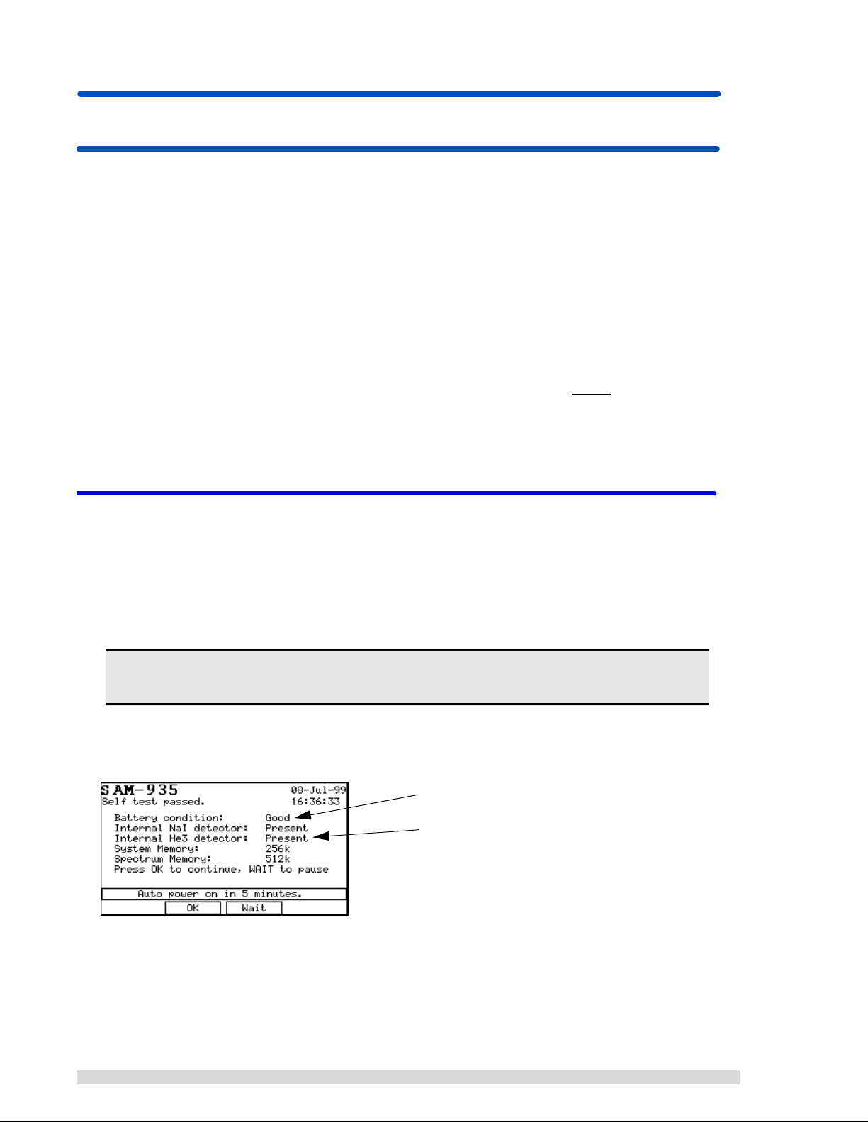
A successful self-test will look something like this:
Note the battery condition here
Note the type of detector(s) installed here.
8 SAM 935™ Instruction Manual
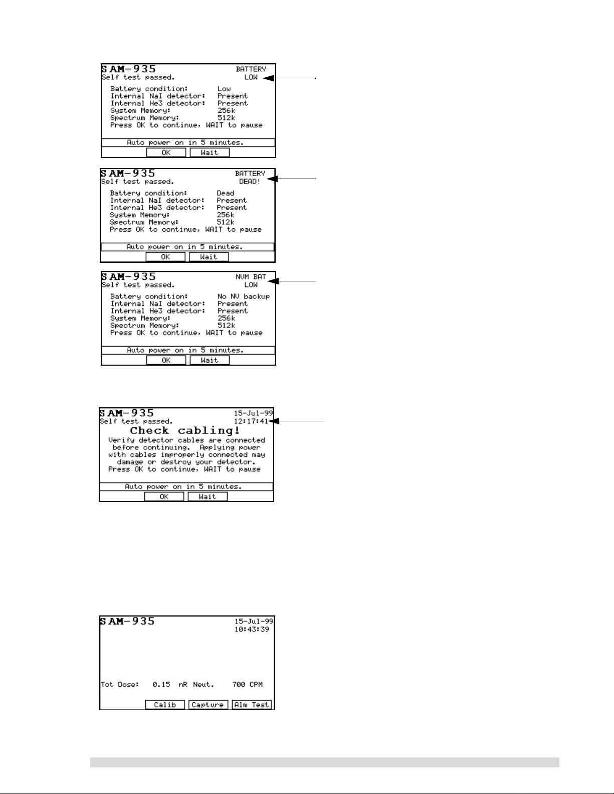
Example of a self-test with a low battery condition. The
Battery Low message will replace the clock. The SAM
935 will proceed with the auto-start, but you should
recharge as soon as possible.
A self-test example where the batteries need to be
recharged. The SAM 935 will completely shut down
within approximately 15 seconds of the Battery Dead
message appearing.
Example of a self-test where the battery backup for
non-volatile information (including spectra and alarms)
has failed. The SAM 935 should be returned to an authorized service center for battery replacement.
If you do not have an internal NaI detector, the SAM 935 will prompt you to check the cabling to the external detector after it completes the self-test:
Check the cabling to the external detector and press
OK (F2) if it’s acceptable. If it’s not, you can press
Wait (F3) to delay the auto-start another 5 minutes.
After the self-test has run, the SAM 935 will wait 5 minutes and then start up. You can press OK (F2) to
immediately start up. Press W
AIT (F3) to delay startup for another 5 minutes.
At this point, the SAM 935 may require an automatic calibration. If so, a prompt will give you the choice to
begin the quick calibration (F2) or to perform a recalibration from the Utilities menu (F3). See Sections
4.2.1 and 3.2, respectively.
When the SAM 935 is ready for operation, the dose rate monitoring screen will appear:
SAM 935™ Instruction Manual 9
The dose rate analysis measures and records isotopes in dose rate units (rather than the confidence levels
used by the Monitor mode). The different modes of operation are explained in Section 5.
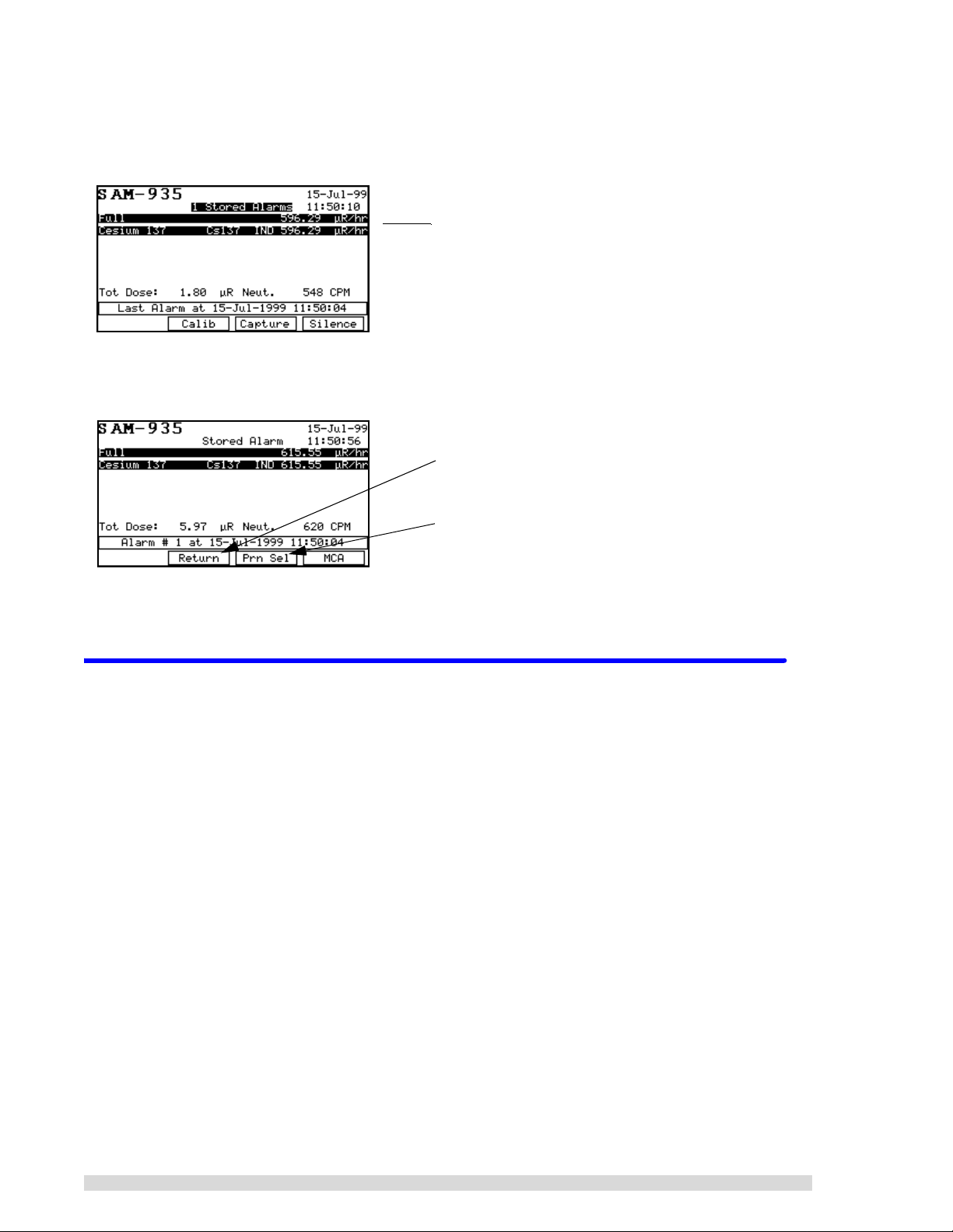
An example of the main dose rate monitoring screen is shown below:
}
If there are stored alarms, you can review them by pressing the ← or → arrow keys from the main
Surveillance monitori ng scr een:
If other display modes are enabled, they will show up as options under the F1 function key. Display modes
are discussed in Section 5.
The dose rate units are recorded in metric abbreviations
of Sievert (Sv) or REMs (R ).
Press F2 to return to Surveillance mode and take more
readings.
Press F3 to print the stored alarm(s); see Section 7.1
for more information about this report.
3.2 Recalibration Procedure
Follow the directions in this section to perform a complete recalibration of the SAM 935. To ensure accurate, reliable results, you should recalibrate the SAM 935:
• when you first install it. It is calibrated at the factory, but it should be recalibrated on site to ensure
reliable results. This requires only a coarse adjustment and background spectrum, and can be
done with the one-button quick calibration on the main screen (F2). See Section 4.2.1 for details.
• whenever the temperature changes drastically (such as moving from indoor to outdoor monitoring). This requires only a coarse adjustment and background spectrum, and can be done with the
one-button quick calibration (F2). See Section 4.2.1 for details.
• if you change the type of detector you are using with it; this requires a coarse and fine calibration.
• If you perform a memory reset.
You perform this 3-step recalibration process from the
This calibration method automatically adjusts hardware parameters such as high voltage and amplifier
gain to achieve a proper energy calibration for the system. The quick calibration method described in Sections 1.2.2 and 4.2.1 does not.
1. Press the U
TIL key to bring up the Utilities menu.
Calibrate Area Monitor
option in the Utilities menu.
10 SAM 935™ Instruction Manual
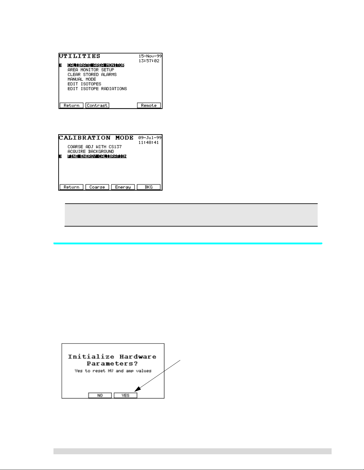
2. Select
Calibrate Area Monitor
from the menu:
The 3 steps needed to perform a recalibration are listed in the order they should be done:
Before beginning the rec alibration process, mak e sure the proper detector is selected using
the
Select/Edit Detector
function under the UTIL key.
3.2.1 Automatic Coarse Calibration
This process requires only a Cs137 source. It may take up to several minutes depending on the activity of
the source.
1. Press the U
2. Select
3. Select
4. If your SAM 935 was factory-calibrated, you will see the message below. Press Y
time you do a coarse calibration; this will cause the SAM 935 to start its hardware adjustment algorithm from scratch. Answer N
bration process quicker) .
5. Point the right front corner of the detector at the Cs137 standard (of approximately 0.5 to 2.0 µCi)
and press S
TIL key.
Calibrate Area Monitor
Coarse Adj With Cs137
TART (F2) to begin data acquisition.
from the list.
from the list, or just press F2.
O (F2) after the initial coarse adjustment (this will also make the cali-
ES (F3) the first
Answer Yes the first time you do a coarse calibration;
answer No thereafter.
SAM 935™ Instruction Manual 11

The spectrum being measured will be displayed as it develops, and if everything is connected correctly, you should be able to watch the spectrum resolve. After each adjustment attempt, a tone
will sound to indicate that the SAM 935 is still adjusting itself. For details about the coarse adjustment, refer to Section 5.6.1.
6. When the adjustment is complete, the two Cs137 peaks will be highlighted, the unit will beep three
times, the
able. At this point, the display should look like the one shown below. If not, press C
check that you have the correct source and retry the operation. If everything is correct, press S
Adjustment Co mp le te
message will appear, and the SAVE (F4) function key will be avail-
ANCEL (F1) and
AVE
(F4) to save the new hardware parameters in memory.
If you experience difficulty during the coarse calibrat ion, press CAN CEL (F1) and the n select
Calibrate Area Monitor
from the
Utilities
menu to start over.
Press Save to finish the coarse calibration.
After you save the coarse calibration adjustment, the SAM 935 will return to the Calibration menu. Continue with calibration by taking a background spectrum next.
3.2.2 Acquire a Background Spectrum
To get accurate identification results, a background spectrum should be taken frequently, and it must be
collected in the same physical location where the monitoring will occur. The background is very important
because it is the point of reference against measured activities.
A new background spectrum should be acquired whenever the ambient background changes, i.e., if the
instrument is moved to a new location or if a patient having received a radionuclide dose enters or leaves
the vicinity. A background spectrum is also required before doing the more accurate fine energy calibration. Background spectra can be acquired at any point. After one week, the SAM 935 will require that you
take another background spectrum.
1. At the Calibration menu, select
2. A background spectrum may not be taken without a prior coarse adjustment. If this is attempted,
the SAM 935 will ask whether you wish to perform the adjustment first. If so, press F3 to perform
the coarse adjustment.
Acquire Backgroun d
Press F2 (Util) if the coarse calibration is not required.
This will take you to the Utilities menu where you can
choose Calibrate Area Monitor to do the background
spectrum.
and press ENTER, or just press F4.
Press F3 (Adjust) if you have not performed a coarse calibration yet. The SAM 935 will complete the coarse
adjustment before resuming acquisition of the background spectrum.
3. Remove all sources from the vicinity of the detector.
12 SAM 935™ Instruction Manual
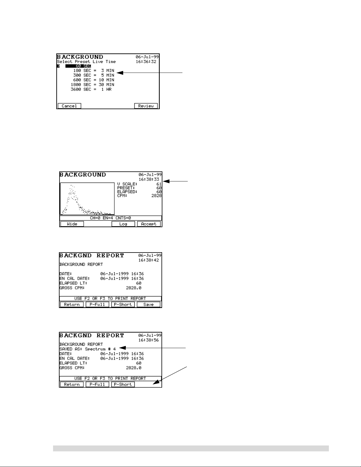
4. The Preset Live Time screen will appear as shown below. Select a live time for background collection and press E
NTER:
For most SAM 935 operations, a collection period of
180 or 300 seconds is generally adequate.
Acquiring a background spectrum takes only a few minutes, depending on the live time preset
selected. For the error in the background spectrum counting statistics to be small compared to the
spectrum of the unknown, the live time preset of the background spectrum should be large compared to that of the unknown spectrum.
5. Once a live time has been selected, the SAM 935 enters the acquire mode for background spectra. Press S
TART (F2) to begin the data acquisition. Data will appear on screen, and the Elapsed
Time will begin counting off:
When the elapsed time matches the live time preset,
the SAM 935 will beep to indicate that data acquisition
is complete. This is a good example of what a background spectrum should look like when complete.
6. Press A
CCEPT (F4), and the SAM 935 will generate a report that can be reviewed on screen and
printed:
7. Press S
AVE (F4) to save the background spectrum, if desired. This will allow the background spec-
trum to be uploaded to a remote computer if needed.
The Background Report will show you when the spectrum has been saved.
Notice that the Save (F4) function goes away after saving the spectrum.
You may also print the report if needed.
8. Press R
ETURN (F1) to leave the background reading. The MCA display will appear. Press Exit, and
the SAM 935 will return to the Calibration menu. Continue with the fine energy calibration.
For more information on the background mode, see Section 5.5.
SAM 935™ Instruction Manual 13
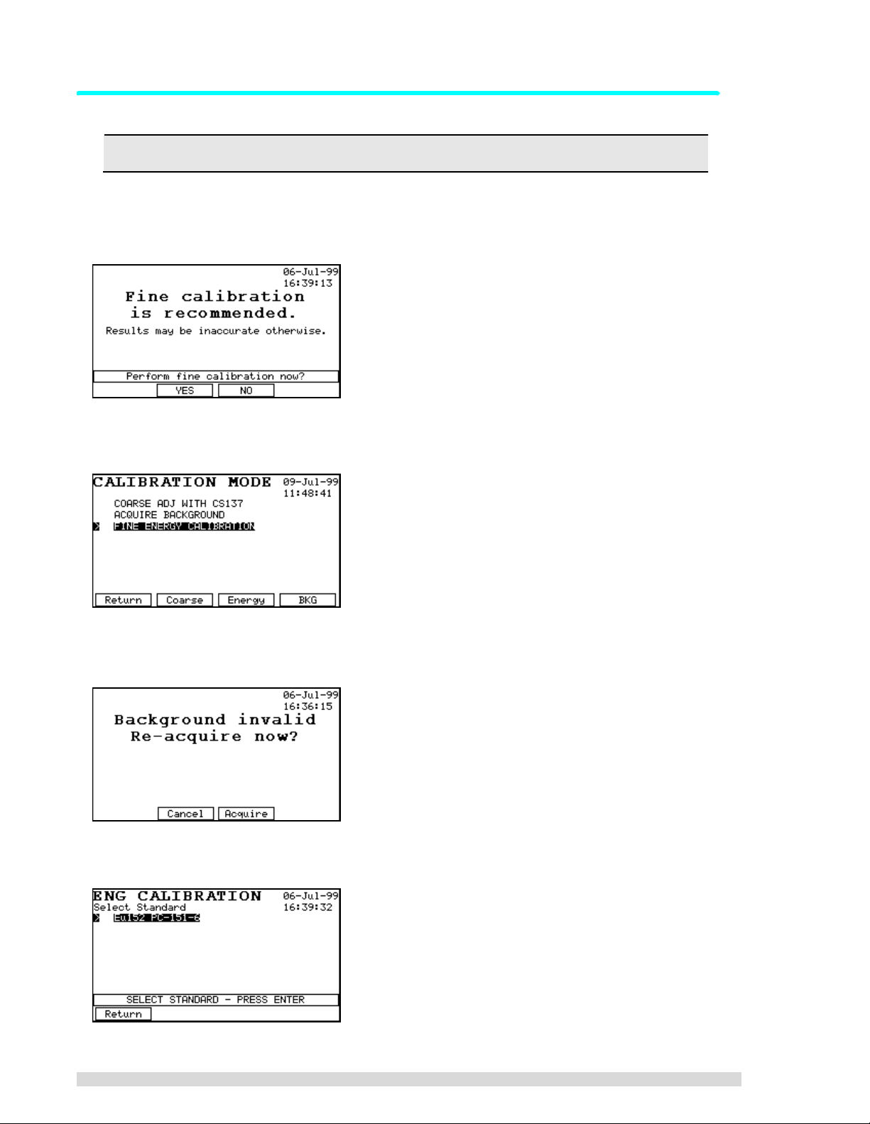
3.2.3 Fine Energy Calibration
Always perform a fine energy calibration if the external detector is changed.
If the SAM 935 has not been previously fine energy calibrated with a multi-line standard such as Eu152,
you will see the message shown below. If no Eu152 source is available, enter the three coefficient numbers as described in Section 3.2.4.
1. Press F2.
2. Select
3. If you have not taken a background spectrum recently, or have not taken one since the last coarse
adjust, you will be forced to do so now. If it’s needed, you will also be forced to do a coarse adjustment before the background reading.
4. You will be presented with a list of isotopes. Select the Eu152 standard from the list and press
E
Fine Energy Calibration
NTER:
from the Calibration menu, or just press F3.
14 SAM 935™ Instruction Manual
If you are using another standard that does not match one in this list, you will have to define it in
the Calibration Standards library. See Section 6.6 for instructions on how to define calibration standards.
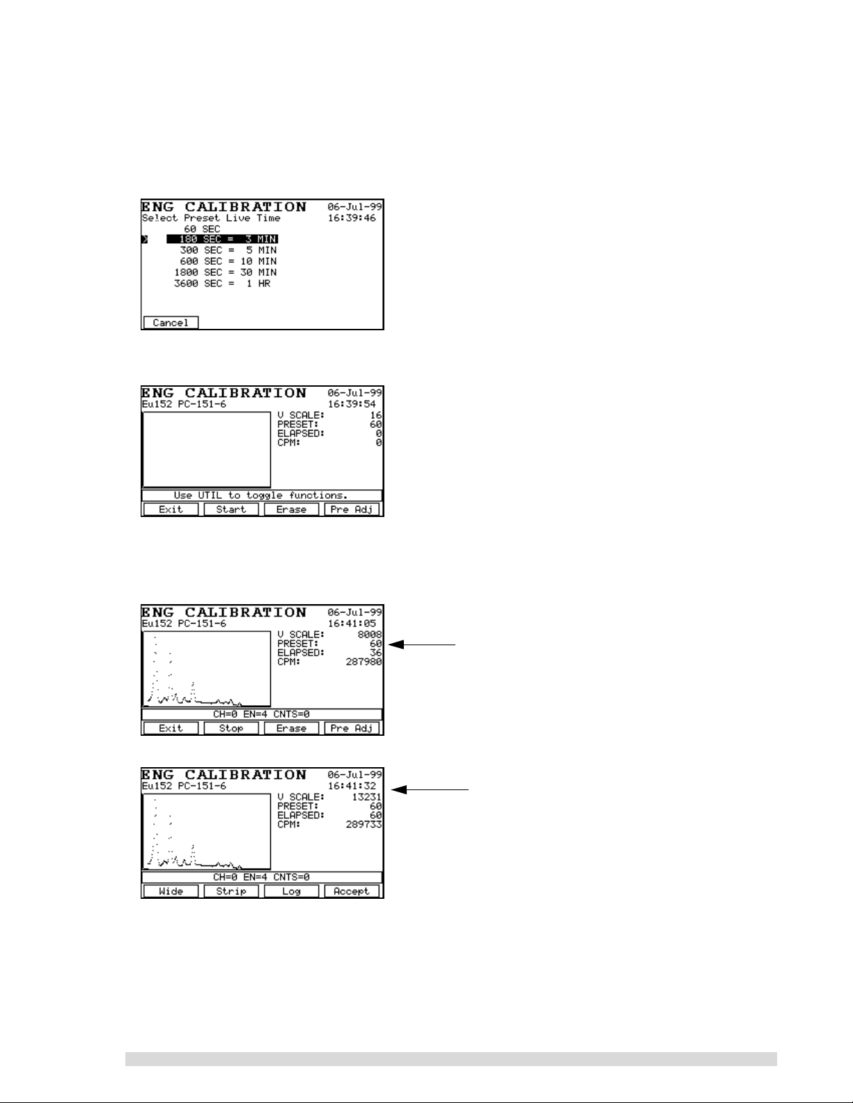
5. Now select a preset live time: If your Eu152 source is between 0.5 and 2 µCi, select a time of 180
seconds. If higher or lower activity, make an appropriate adjustment in count time.
6. Place the standard in front of the detector and press S
TART (F2).
7. When the SAM 935 beeps to indicate that data acquisition is complete, check the spectrum to verify you have counted the correct standard (i.e., about ten peaks covering nearly the entire energy
range), and if so, press A
CCEPT (F4).
Example of a fine energy calibration in progress.
Note how the function keys change in this screen
versus the next one.
Example of a completed fine energy calibration.
Press Accept (F4) after reviewing.
SAM 935™ Instruction Manual 15
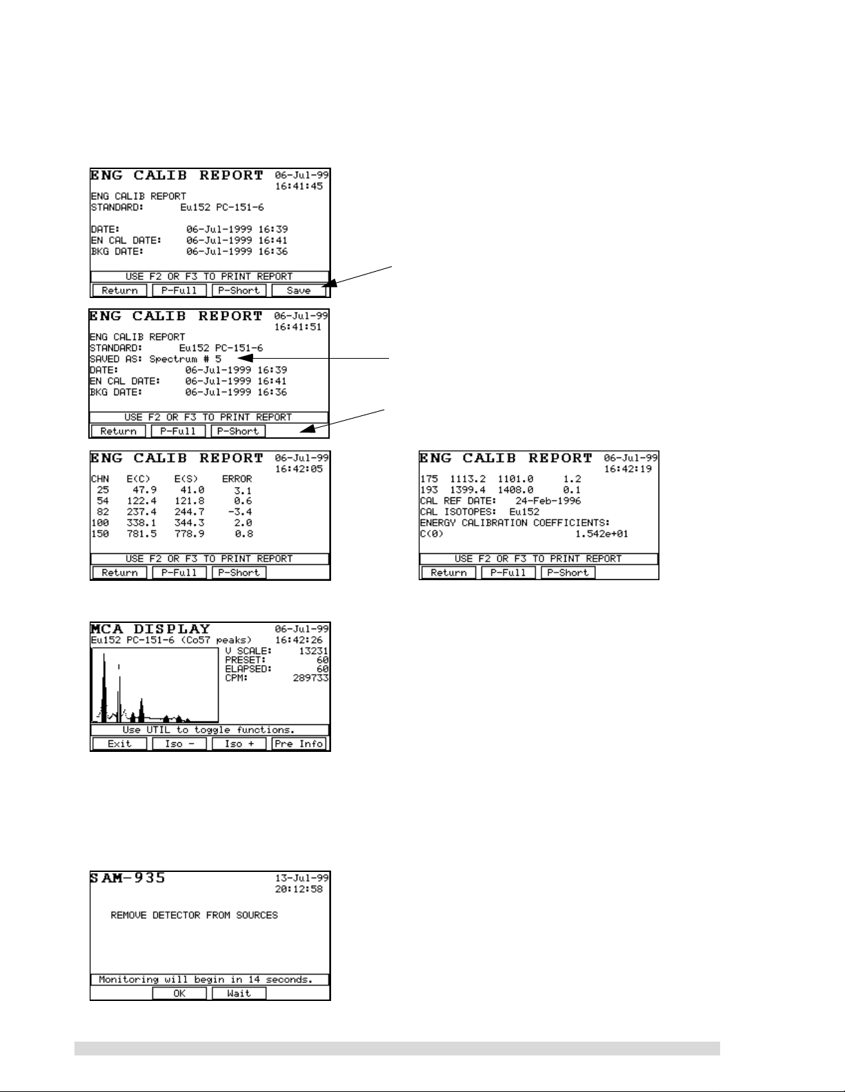
8. The calibration report will appear on the display after you accept the calibration; scroll through it
using the arrow keys to see all of it. The SAM 935 should find seven peaks and the energy errors
th
(4
column) should be in the range ±5 keV. Use the arrow keys to see the details of the report or
print short or long versions using the P-F
ULL and P-SHORT keys.
Press F4 to save the fine energy calibration, if
desired. This allows the fine calibration to be
uploaded to a PC if needed.
The Energy Calibration Report will show you when
the spectrum has been saved.
Notice that the Sav e (F 4) function goes away after
saving the spectrum.
9. When you press R
ETURN (F1) to leave the energy calibration report, the spectrum will display
10. Remove the Eu152 source from the vicinity of the detector.
11. Press E
XIT (F1) to leave the spectrum display; press RETURN (F1) once more to leave the
Calibration menu.
12. You will be prompted to remove the Eu152 source from the vicinity of the detector. The SAM 935
will begin its automatic countdown to begin dose rate monitoring:
16 SAM 935™ Instruction Manual

3.2.4 Calibration with Three Coefficients
To enter the energy calibration factors manually, the factors from a previous live energy calibration for this
unit and matching detector must be available. These numbers can be found on the printout normally done
at the end of a live energy calibration. Alternatively, the numbers can be those recorded earlier from a previous manual calibrati on with the thr ee coe fficients.
1. Press the U
Setup
2. Do NOT change anything in this screen. Press C
TIL key to bring up the Utilities menu. Use the arrow keys to select
. The first screen is the Energy Match Window:
ANCEL (F1) 10 times until you see the question
Analysis Tools
SET FINE ENGY COEFF?
3. Press Y
ES (F2).
The next three screens are standard number entry screens. Change the factors as needed. On
each screen, when the correct value is shown, press E
NTER.
4. Return to the normal operating screen.
3.3 Configure Dose Rate Units and Trigger
Because the SAM 935 operates in Surveillance mode by default (also called dose rate monitoring), configure the Dose Rate Units and Dose Rate Trigger options in the Monitor Setup menu:
1. Press the U
TIL key to bring up the Utilities menu.
SAM 935™ Instruction Manual 17
Loading...