


™
SAM 935
Surveillance and Measurement System
Instruction Manual
Berkeley Nucleonics Corporations
3060 Kerner Boulevard #2
San Rafael, CA 94901 USA
800-234-7858
415-453-9955
fax: 415-453-9956
http:/www.berkeleynucleonics.com

Firmware Release 02.05.19
U. S. Patent No. 5608222
© 1995-1999 All rights reserved.
Printed in U.S.A. - 03/30/00
WARRANTY
Berkeley Nucleonics Corporation warrants all instruments, including component parts, to be free from defects in material and
workmanship, under normal use and service for a period of one year. If repairs are required during the warranty period, contact the
factory for component replacement or shipping instructions. Include the serial number of the instrument. This warranty is void if the
unit is repaired or altered by others than those authorized by Berkeley Nucleonics Corporation.
IMPORTANT!! PLEASE READ CAREFULLY
NOTIFICATION OF COPYRIGHT
THE FIRMWARE IN THIS DEVICE IS PROTECTED BY COPYRIGHT LAWS AND INTERNATIONAL TREATY. YOU MUST TREAT
THE FIRMWARE LIKE ANY OTHER COPYRIGHTED MATERIAL. COPYRIGHT LAWS PROHIBIT MAKING ADDITIONAL COPIES
OF THE FIRMWARE FOR ANY REASON OTHER THAN SPECIFICALLY DESCRIBED IN THE LICENSE BELOW. YOU MAY NOT
COPY THE WRITTEN MATERIALS ACCOMPANYING THE PRODUCT.
2 SAM 935™ Instruction Manual

Table of Contents
1 Introduction . . . . . . . . . . . . . . . . . . . . . . . . . . . . . . . . .1
1.1 How To Use This Manual . . . . . . . . . . . . . . . . . . . . . . . . . . . . . . 1
1.2 Quick Reference . . . . . . . . . . . . . . . . . . . . . . . . . . . . . . . . . . . 3
1.2.1 Power On the SAM 935 . . . . . . . . . . . . . . . . . . . . . . . . . . 3
1.2.2 Quick Calibration and Background Reading . . . . . . . . . . . . . . . . 3
1.2.3 Take Samples and Review Alarms. . . . . . . . . . . . . . . . . . . . . 5
2 Connecting Hardware . . . . . . . . . . . . . . . . . . . . . . . . . . . .6
2.1 Connecting Power . . . . . . . . . . . . . . . . . . . . . . . . . . . . . . . . . . 6
2.2 Connecting to a Printer . . . . . . . . . . . . . . . . . . . . . . . . . . . . . . . . 6
2.3 Connecting to a Remote Computer . . . . . . . . . . . . . . . . . . . . . . . . . 7
2.4 Connecting an Optional External Detector . . . . . . . . . . . . . . . . . . . . . . 7
3 Configuring the SAM 935 . . . . . . . . . . . . . . . . . . . . . . . . . .8
3.1 Starting Up the SAM 935 . . . . . . . . . . . . . . . . . . . . . . . . . . . . . . . 8
3.2 Recalibration Procedure . . . . . . . . . . . . . . . . . . . . . . . . . . . . . . 10
3.2.1 Automatic Coarse Calibration . . . . . . . . . . . . . . . . . . . . . . 11
3.2.2 Acquire a Background Spectrum . . . . . . . . . . . . . . . . . . . . . 12
3.2.3 Fine Energy Calibration. . . . . . . . . . . . . . . . . . . . . . . . . . 14
3.2.4 Calibration with Three Coefficients . . . . . . . . . . . . . . . . . . . . 17
3.3 Configure Dose Rate Units and Trigger . . . . . . . . . . . . . . . . . . . . . . 17
3.4 Dose Rate Calibration . . . . . . . . . . . . . . . . . . . . . . . . . . . . . . . 19
4 Operating the SAM 935 . . . . . . . . . . . . . . . . . . . . . . . . . . 20
4.1 Recommended Daily Operating Procedure . . . . . . . . . . . . . . . . . . . . 20
4.2 Powering the SAM 935 On . . . . . . . . . . . . . . . . . . . . . . . . . . . . . 20
4.2.1 Quick Calibration Adjustment. . . . . . . . . . . . . . . . . . . . . . . 22
4.3 Powering the SAM 935 Off . . . . . . . . . . . . . . . . . . . . . . . . . . . . . 23
4.4 Taking Readings in Surveillance Mode . . . . . . . . . . . . . . . . . . . . . . 24
4.5 Reviewing Alarms . . . . . . . . . . . . . . . . . . . . . . . . . . . . . . . . . 25
4.6 The SAM 935 Interface . . . . . . . . . . . . . . . . . . . . . . . . . . . . . . . 26
4.6.1 The Front Panel . . . . . . . . . . . . . . . . . . . . . . . . . . . . . 26
4.6.2 Function Keys . . . . . . . . . . . . . . . . . . . . . . . . . . . . . . 27
4.6.3 Scrolling Through Long Menus. . . . . . . . . . . . . . . . . . . . . . 27
4.6.4 Editing Instructions . . . . . . . . . . . . . . . . . . . . . . . . . . . . 27
4.6.5 The Utilities Screen. . . . . . . . . . . . . . . . . . . . . . . . . . . . 29
5 SAM 935 Modes of Operation . . . . . . . . . . . . . . . . . . . . . . 30
5.1 The Surveillance Mode of Operation . . . . . . . . . . . . . . . . . . . . . . . . 30
5.2 The Monitor Mode of Operation . . . . . . . . . . . . . . . . . . . . . . . . . . 31
5.3 The Detail Mode of Operation . . . . . . . . . . . . . . . . . . . . . . . . . . . 32
5.4 Manual Mode . . . . . . . . . . . . . . . . . . . . . . . . . . . . . . . . . . . . 32
5.4.1 MCA Presets . . . . . . . . . . . . . . . . . . . . . . . . . . . . . . . 34
5.4.2 Manual Hardware Adjustments. . . . . . . . . . . . . . . . . . . . . . 35
5.4.3 Manual Mode Utilities. . . . . . . . . . . . . . . . . . . . . . . . . . . 36
5.5 Background Mode . . . . . . . . . . . . . . . . . . . . . . . . . . . . . . . . . 37
SAM 935™ Instruction Manual 1

5.6 Calibration Mode . . . . . . . . . . . . . . . . . . . . . . . . . . . . . . . . . . 38
5.6.1 Manual Coarse Adjust with Cs137 . . . . . . . . . . . . . . . . . . . . 38
5.6.2 Fine Energy Calibration . . . . . . . . . . . . . . . . . . . . . . . . . . 39
6 Utilities . . . . . . . . . . . . . . . . . . . . . . . . . . . . . . . . . . 40
6.1 Area Monitor Setup . . . . . . . . . . . . . . . . . . . . . . . . . . . . . . . . . 41
6.1.1 Set the Sample Time . . . . . . . . . . . . . . . . . . . . . . . . . . . 41
6.1.2 Select Triggers . . . . . . . . . . . . . . . . . . . . . . . . . . . . . . 42
6.1.3 Set the Default Trigger Levels . . . . . . . . . . . . . . . . . . . . . . 43
6.1.4 Preventing False Alarms . . . . . . . . . . . . . . . . . . . . . . . . . 44
6.1.5 Calibrate Dose Rate. . . . . . . . . . . . . . . . . . . . . . . . . . . . 45
6.1.6 Configure Alarm Hardware . . . . . . . . . . . . . . . . . . . . . . . . 47
6.2 Clear Stored Alarms . . . . . . . . . . . . . . . . . . . . . . . . . . . . . . . . 47
6.3 Edit Isotopes . . . . . . . . . . . . . . . . . . . . . . . . . . . . . . . . . . . . 47
6.3.1 Adding a New Isotope. . . . . . . . . . . . . . . . . . . . . . . . . . . 48
6.3.2 Enable/Disable Isotopes . . . . . . . . . . . . . . . . . . . . . . . . . 48
6.3.3 Editing an Isotope . . . . . . . . . . . . . . . . . . . . . . . . . . . . . 48
6.4 Edit Isotope Radiations . . . . . . . . . . . . . . . . . . . . . . . . . . . . . . . 49
6.5 Print Databases . . . . . . . . . . . . . . . . . . . . . . . . . . . . . . . . . . . 49
6.6 Edit Calibration Standards . . . . . . . . . . . . . . . . . . . . . . . . . . . . . 50
6.6.1 Adding a Standard . . . . . . . . . . . . . . . . . . . . . . . . . . . . 50
6.6.2 Deleting a Standard . . . . . . . . . . . . . . . . . . . . . . . . . . . . 50
6.6.3 Editing a Standard . . . . . . . . . . . . . . . . . . . . . . . . . . . . 50
6.7 Select / Edit Detector . . . . . . . . . . . . . . . . . . . . . . . . . . . . . . . . 51
6.8 Analysis Tools Setup . . . . . . . . . . . . . . . . . . . . . . . . . . . . . . . . 52
6.9 Select Spectrum Draw Style . . . . . . . . . . . . . . . . . . . . . . . . . . . . 53
6.10 Show System Information . . . . . . . . . . . . . . . . . . . . . . . . . . . . . . 53
6.11 Set Serial Speed . . . . . . . . . . . . . . . . . . . . . . . . . . . . . . . . . . 54
6.12 Set Report Title String . . . . . . . . . . . . . . . . . . . . . . . . . . . . . . . 54
6.13 Set System Clock—Date and Time . . . . . . . . . . . . . . . . . . . . . . . . . 54
6.14 Set Backlight Delay Time . . . . . . . . . . . . . . . . . . . . . . . . . . . . . . 55
6.15 Print Stored Spectra . . . . . . . . . . . . . . . . . . . . . . . . . . . . . . . . 55
6.16 Clear Stored Spectra . . . . . . . . . . . . . . . . . . . . . . . . . . . . . . . . 55
6.17 Switch to Remote . . . . . . . . . . . . . . . . . . . . . . . . . . . . . . . . . . 56
6.18 Clear ALL Data and Reset . . . . . . . . . . . . . . . . . . . . . . . . . . . . . 56
7 Reports . . . . . . . . . . . . . . . . . . . . . . . . . . . . . . . . . . 57
7.1 Area Monitor Report of Alarms . . . . . . . . . . . . . . . . . . . . . . . . . . . 57
7.2 Background Report . . . . . . . . . . . . . . . . . . . . . . . . . . . . . . . . . 57
7.3 Energy Calibration Report . . . . . . . . . . . . . . . . . . . . . . . . . . . . . 58
7.4 Manual MCA Report . . . . . . . . . . . . . . . . . . . . . . . . . . . . . . . . 59
7.5 Database Reports . . . . . . . . . . . . . . . . . . . . . . . . . . . . . . . . . . 60
8 Specifications . . . . . . . . . . . . . . . . . . . . . . . . . . . . . . 61
Appendix A: AutoLoad . . . . . . . . . . . . . . . . . . . . . . . . . . . 63
A.1 Installing AutoLoad . . . . . . . . . . . . . . . . . . . . . . . . . . . . . . . . . 63
A.2 Using AutoLoad . . . . . . . . . . . . . . . . . . . . . . . . . . . . . . . . . . . 63
A.3 Device-Specific Notes for the SAM 935 . . . . . . . . . . . . . . . . . . . . . . . 65
2 SAM 935™ Instruction Manual

1. Introduction
Welcome to the SAM 935™, a portable surveillance and measurement system for detecting and identifying
multiple nuclides.The SAM 935 identifies mixed isotopes, providing quantified results and time-slice
analysis.
The SAM 935 has a large feature set that addresses almost any gamma radiological task. It can be used in
a very simple mode that does not require any radiological experience. The purpose of the Quick Reference
in Section 1.2 is to give the operator the information needed to use the SAM 935 for radiation detection
and isotopic identification. Complete discussions of the full SAM 935 functionality can be found in the
remainder of the manual.
The modes of operation are described in Section 5. The SAM 935 is not just a MCA since it has many
automated and easy-to-use features with real time analysis. Therefore, operation solely from the Manual
mode does not use the intelligence that makes the SAM a very unique instrument. The operator should be
aware that the SAM 935 is designed to be operated primarily in the Surveillance, Monitor, or Detail mode.
In any of these modes an alarm may be stored, reviewed, and dragged into the manual MCA for further
analysis. This not only makes for ease of operation but allows greater functionality and immediate identification of isotopes. Furthermore, these primary modes of operation allow review and printout of each stored
alarm. The Manual mode will not allow review of stored events, dose-rate measurements, neutron measurements, or many of the time slice features built into this instrument.
QuantumMCA and QuantumGold are PC software packages that allow up to 8 MCAs to be controlled at
one time with up to 16K of real time display. QuantumMCA is the standard software and QuantumGold is
the premier software for quantitative analysis. These packages are available with their own documentation
on operation. Appendix A of this manual gives instructions for loading the PC software (see also Section
6.17 for remote access). This software will allow analysis in 256 QCC or linear, 512 QCC or linear, and
1024 linear modes. When using the SAM 935 without a PC, operation is limited to 256 and 512 QCC. However, all stored data (including 1024 linear that is not stored) may be transferred from the SAM to the PC
for analysis.
1.1 How To Use This Manual
This manual uses the following typographic conventions:
File Menu names are shown in bold mixed case, indicating the SAM 935
screen mode.
E
NTER, F1…F4 Small capital letters are used for the names of keys to be pressed on the
SAM 935.
Calibrate Area Monitor
SAM 935™ Instruction Manual 1
Choices in menu listings and on-screen prompts are shown in italics.

This page intentionally blank.
2 SAM 935™ Instruction Manual
1.2 Quick Reference
Operating the SAM 935 is a simple 3-step process:
1. Power on the SAM 935.
2. If prompted to do so, take a quick calibration and background reading.
3. Take samples and review any alarms.
1.2.1 Power On the SAM 935
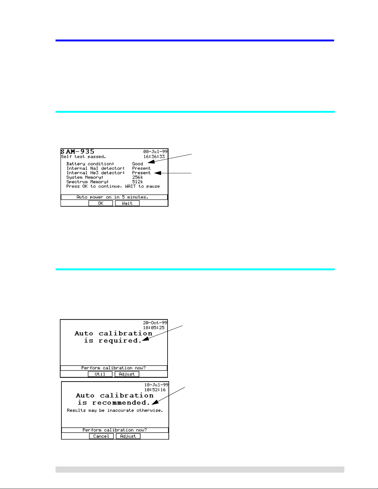
When you power on the SAM 935, it will first run a self-test as shown below:
Note the battery condition here.
Note the type of detector(s) installed here.
After the self-test has run, the SAM 935 will proceed to auto-start after 5 minutes have elapsed, after which
you can begin operating the unit.
Y ou can also press OK (F2) to immediately start up. Press W
AIT (F3) to delay startup for another 5 minutes.
If you are not prompted to take a calibration, you can proceed to take readings; skip to Section 1.2.3.
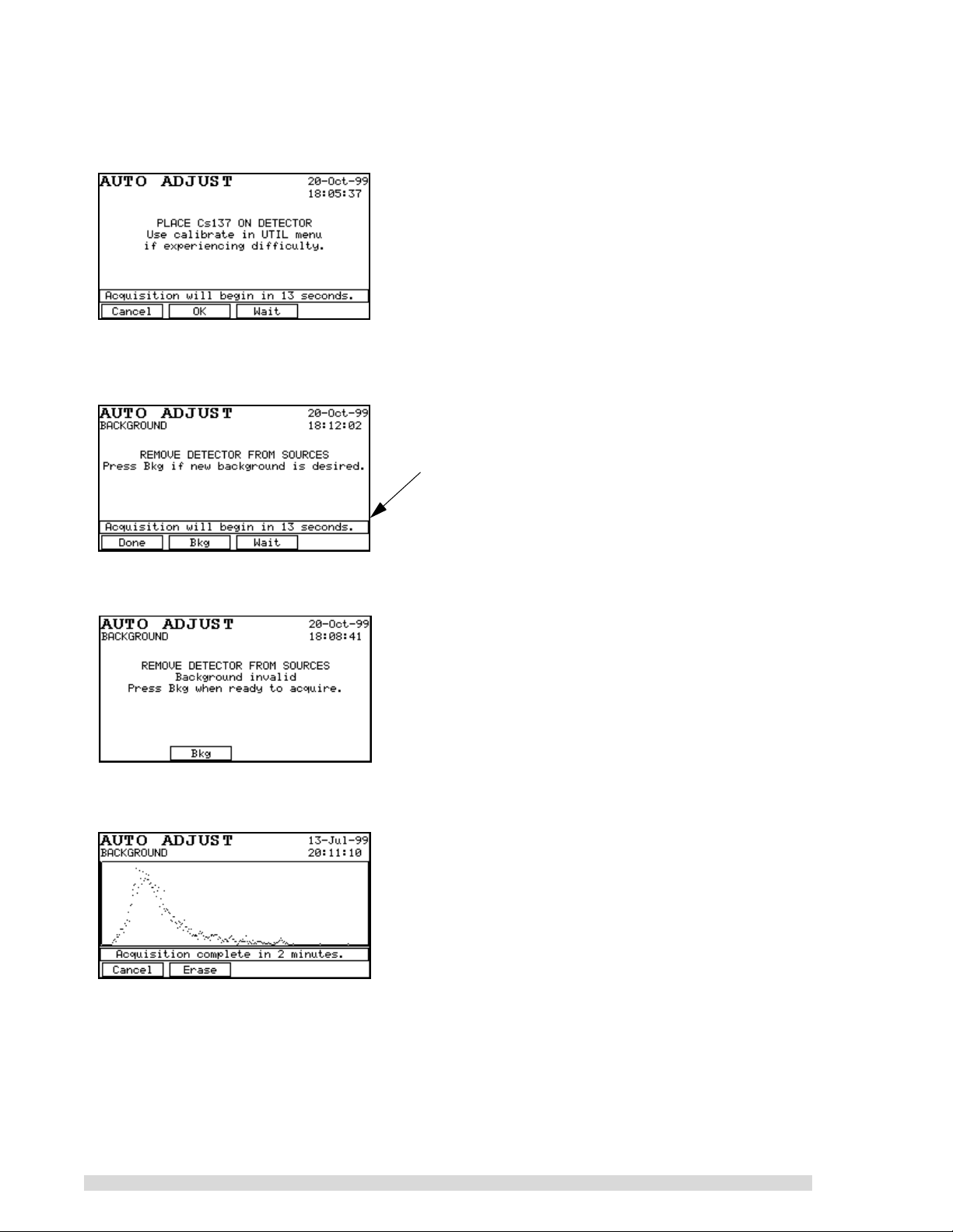
1.2.2 Quick Calibration and Background Reading
After the self-test, the SAM 935 may detect that a calibration and background reading are needed. If it
does, you will see one of the two prompts shown below. Until you perform the adjustment, these messages
will show up every time the SAM 935 is powered on.
“Calibration required” means this is the first time the SAM
935 has been powered up, or some important setting
changed that requires calibration. Note that your two
choices are to perform the cal ibration adj ustment (F3) or to
enter the Utilities menu to adjust the instrument settings
(F2).
The “calibration recommended” prompt appears when a
calibration has not been performed in over a week. Note
that your two choices are to perform the calibration adjustment (F3) or to continue with st artup witho ut perfor ming the
calibration (F2). If you choose to skip the calibration, the
monitoring results may not be reliable.
SAM 935™ Instruction Manual 3
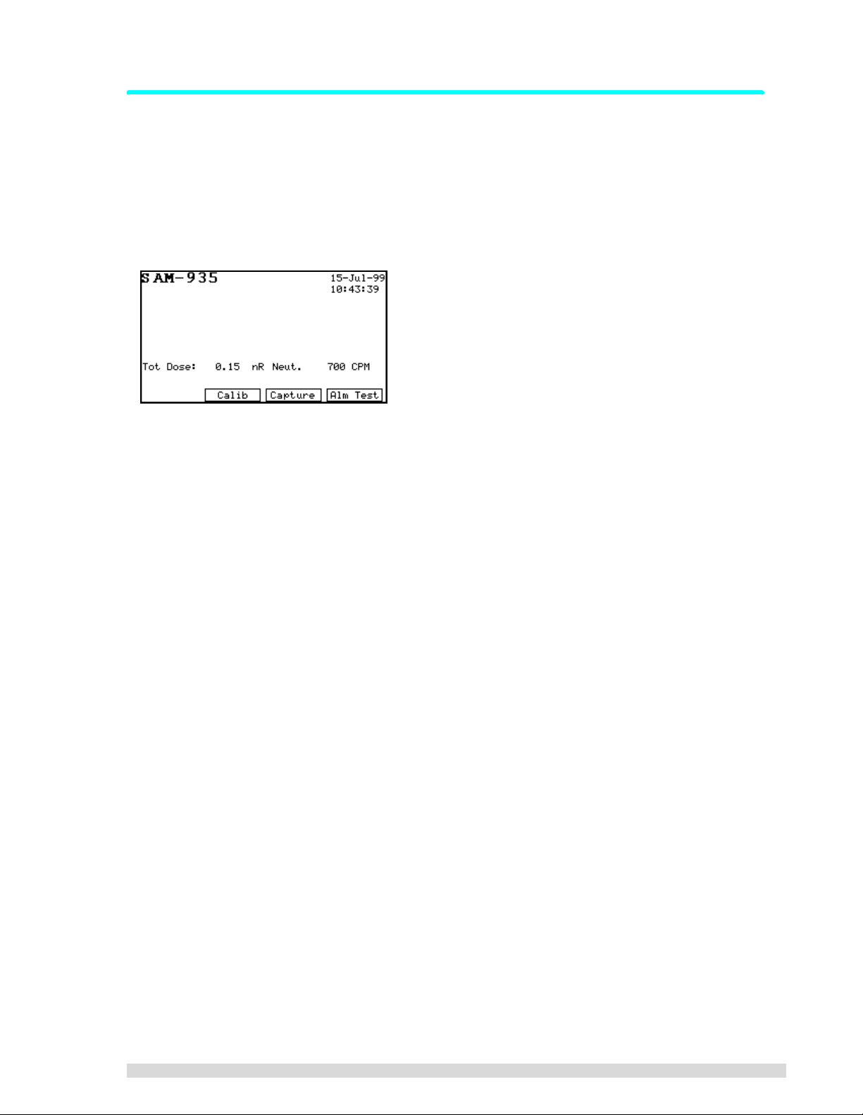
1. Press the ADJUST (F3) button.
2. You will be prompted to place the Cs137 standard in front of the detector. Position the standard as
closely as possible to the right front corner of the SAM 935, where the internal detector resides:
3. After the SAM 935 has finished its coarse calibration, it will beep two times and give you the opportunity to take a background spectrum. Remove the Cs137 source from the vicinity of the detector
and press B
KG (F2) to begin taking the background reading:
If you do not take a background reading, the SAM 935 will
enter its monitoring mode after a preset 15-second delay.
Press Wait (F3) to restart the 15-second countdown if you
need more time to remove the source.
If the SAM 935 detects that the background reading is unusable or non-existent, it will present this
screen that requires you to take a background reading:
4. The automatic background adjustment will take 1 minute (the factory setting). You will see the
spectrum resolve on screen as it is acquired:
5. The SAM 935 may recommend a fine calibration at this point, if the external detector was changed
or if the fine calibration has been corrupted (refer to Section 3.2.3). Normally, however, only the
coarse adjustment and background reading are required.
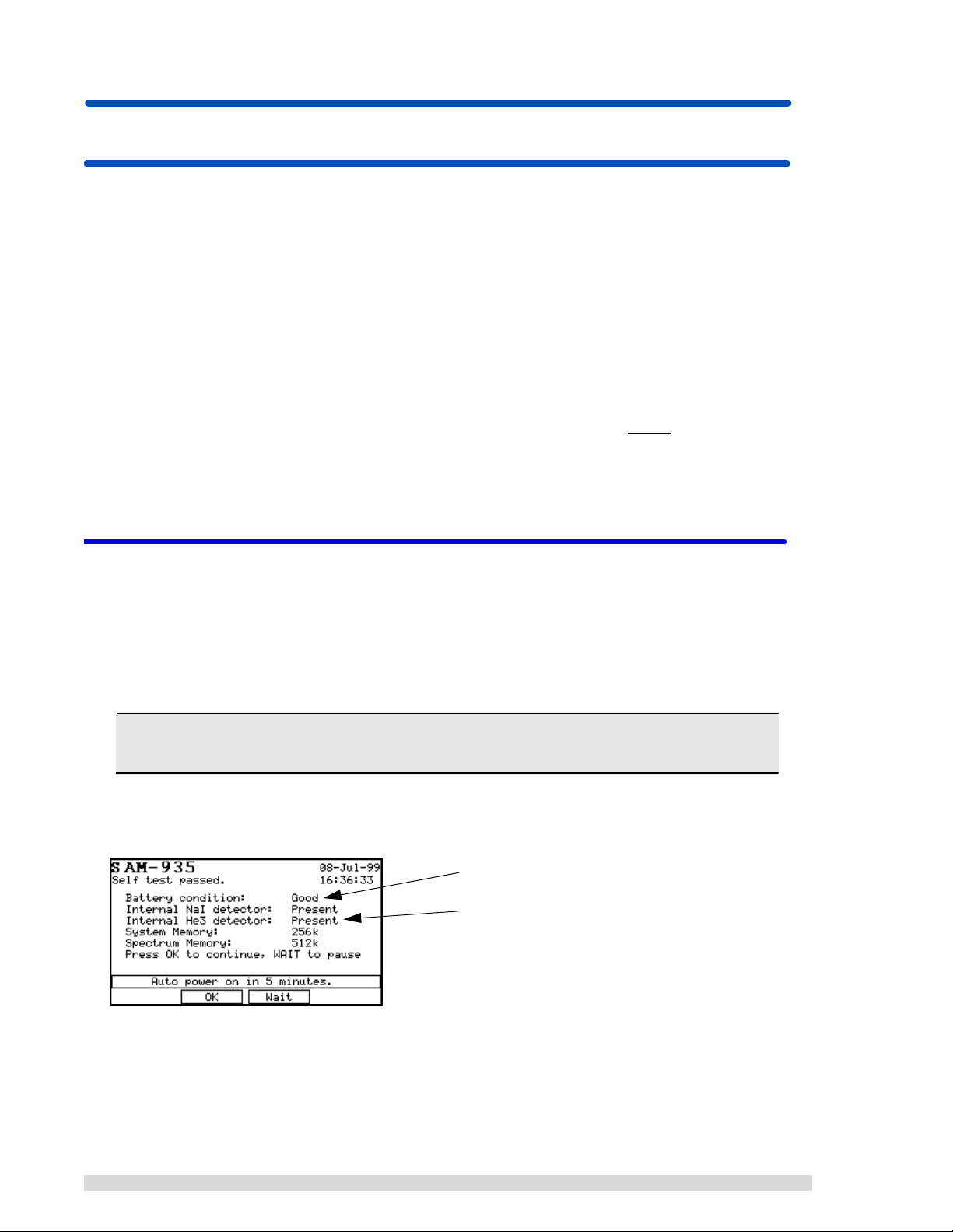
6. When the calibration adjustments are done, the dose rate monitoring screen will appear and you
can begin taking samples.
For more information on quick calibration, refer to Section 4.2.1.
4 SAM 935™ Instruction Manual
1.2.3 Take Samples and Review Alarms
The monitoring display of the SAM 935 will look different depending on the operating mode of the instrument. The default operating mode for the SAM 935 is Surveillance mode, also called dose rate monitoring.
In Surveillance mode, the SAM 935 continuously takes readings and analyzes isotopes in dose rate units,
saving and reporting any alarm conditions (when the dose rate exceeds the dose rate trigger).
The dose rate monitoring screen will look something like this (depending on how the SAM 935 was
configured):
1. Hold the SAM 935 in front of you so you can read the display.
2. Take readings by pointing the right front corner of the detector at the sample, as closely as possible. (The internal detector is installed on the right side of the SAM 935. If using the
factory-supplied, optional external detector, position the detector and sample in close proximity to
each other.) The SAM 935 will take continuous readings.
3. To manually save a reading or alarm, press C
alarm, if any, will be terminated when you press C
APTURE (F3) to save the current display. The current
APTURE. If the condition continues to alarm, a
new alarm will be created and you will again have the choice to capture it or not.
4. To review alarms, use the right and left arrow buttons. Use the right arrow button to review the
alarms in order they were taken (newest to oldest). Use the left arrow button to review alarms in
reverse order (oldest to newest).
SAM 935™ Instruction Manual 5

2. Connecting Hardware
This chapter describes how to connect optional, peripheral devices to the SAM 935. The SAM 935 consists
of the spectrometer electronics, internal detector(s), and optionally, an external detector. Simply follow the
instructions below for connecting a printer or personal computer, and if purchased, the optional external
detector.
There are two tubes on each end of the SAM 935; the left tube (if you are holding the SAM 935 in normal
operating mode) holds the battery pack. The right tube holds the internal detector. The optional internal
neutron detector is installed along the front edge of the SAM 935.
The connection ports for the analog power cord and peripheral devices are located on the front left side of
the SAM 935 (when holding the unit in normal operating mode), next to the battery pack tube. Slide the
cover back to reveal the ports.
An RS-232 serial connector (DB9M), above the power port, is used to connect the SAM 935 to a printer or
to a host computer; see Sections 2.2 and 2.3 for more information.
2.1 Connecting Power
The SAM 935 operates off of an internal battery pack, which is located in the left tube (if you are holding
the unit in normal operating mode).
To guarantee good results, recharge the SAM 935’s battery pack when you first receive the unit from the
factory. Thereafter, the clock on the top panel display will be replaced with a
the battery pack needs to be recharged or replaced.
1. To recharge the battery pack, simply plug the factory-supplied battery charger in to the power port
on the front panel (holding the unit in normal operating mode). The power port is located below the
RS-232 port and next to the power on/off button.
2. Plug the other end into a standard wall outlet. It will take approximately 4 hours to recharge a completely empty battery pack. The batteries will recharge only if the SAM 935 is turned off during this
time.
Always use the factory-supplied battery charger to ensure that the batteries are not damaged.
3. The SAM 935 can be operated continuously from the battery charger; however, it cannot simultaneously be powered on and recharge the internal battery pack.
4. The SAM 935's power switch is the push button next to the power port.
Battery Low
message when
2.2 Connecting to a Printer
The SAM 935 may be connected to a printer for printing a variety of reports. If you purchased a preconfigured printer from BNC, simply attach the printer to the serial port on the front panel of the SAM 935,
located above the power on/off switch, and it is ready for use.
If you are using another printer, follow the instructions in the rest of this section:
6 SAM 935™ Instruction Manual

Most printers compatible with the Epson command set (9-pin,
24-pin, and ink jet printers) are supported. If your printer does not
have an option for a serial port connection, you may need to purchase an RS-232 serial to Centronics parallel adapter (available as
an option from BNC). Otherwise, the printer may be attached to the
SAM 935 in exactly the same fashion as you would attach it to the
serial port of any computer.
Set the printer serial configuration to 19,200 baud (or another baud
rate if you have changed the SAM 935 defaults), 8 data bits, 1 start
bit, 1 stop bit, no parity. It is also important, if your printer has this
feature, to set the font to the Latin1/European font rather than the
italic font so that special characters will be printed correctly. See
SAM 935 RS-232 Connections
Power
Receive Data
Transmit Data
No Connection
Ground
No Connection
Request to Send
Clear to Send
No Connection
VCC
RX
TX
GND
TRS
CTS
1
2
3
4
5
6
7
8
9
your printer manual for details.
After starting up the SAM 935, set the serial speed to match the printer’s in the SAM 935 Utilities menu;
see Section 6.11.
2.3 Connecting to a Remote Computer
The SAM 935 may be connected to a remote computer running the PGT QUANTUM MCA® software. The
Quantum software comes with AutoLoad, a program for uploading spectra saved in SAM 935 to a personal
computer. The installation and use of this program is covered in Appendix A: AutoLoad.
To make the hardware connection between the SAM 935 and the personal computer, a null modem cable
is required. The SAM 935 may be connected to any serial port of the host computer, provided that this
serial port is accessible from Microsoft Windows
®
.
1. Simply align the connector on one end of the cable with the 9-pin serial connector on the SAM 935
(RS-232), and press to insert.
2. Repeat with the connector on the host computer.
3. After starting up the SAM 935, set the serial speed to match the printer’s in the SAM 935 Utilities
menu; see Section 6.11.
4. In the hardware search program, select the baud rate and COM port to which the SAM 935 is
attached.
5. On the SAM 935, press the U
6. Press the U
PDATE button. The Quantum hardware search software should automatically detect the
SAM 935 when you press the U
TIL key. Select REMOTE (F4).
PDATE button in its MCA Devices Auto Configuration window.
2.4 Connecting an Optional External Detector
If you purchased an optional external detector with the SAM 935, attach the supplied LEMO connector to
the port on the right-hand side of the SAM 935 (holding the unit in normal operating mode). The other end
of the LEMO connector attaches to the external detector.
SAM 935™ Instruction Manual 7
3. Configuring the SAM 935
This chapter describes in detail how to set up the SAM 935 for daily operation. Most of the setup takes
place in the Utilities menu.
Summary of Steps to Take:
1. Connect the hardware as described in the previous section.
2. Power on the SAM 935 and let it self-test and start up.
3. Perform a recalibration of the SAM 935: (a) a coarse adjustment, (b) a background spectrum, and
if using a new detector, (c) a fine energy calibration. T o complete all three calibration steps, you will
need a Cs137 source and an Eu152 source.
N
OTE: When you first install the SAM 935 and whenever the temperature changes drastically, you must
perform a coarse adjustment with Cs137 and a background spectrum. You MUST
with both sources (including a fine energy calibration) if you change the detector.
4. Configure the dose rate units of measurement and alarm trigger.
5. Configure any other settings found in the Utilities menu (for details, see Section 6).
3.1 St arting Up the SAM 935
do a recalibration
After connecting the hardware as described in the previous section, press the white power on/off switch to
turn on the SAM 935. It will automatically perform a self-test before starting up. The examples below show
the different self-test results that you may see.
The SAM 935 display screen has a backlight that will come on automatically when a key is pressed, unless
the default settings are changed.
Note: If you just performed a memor y reset, you will be prompted to selec t a detector before
the self-test screen appears. See Section 6.18 for more information.
A successful self-test will look something like this:
Note the battery condition here
Note the type of detector(s) installed here.
8 SAM 935™ Instruction Manual
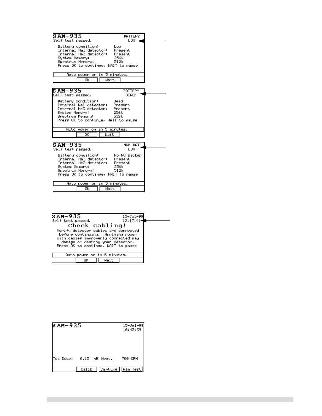
Example of a self-test with a low battery condition. The
Battery Low message will replace the clock. The SAM
935 will proceed with the auto-start, but you should
recharge as soon as possible.
A self-test example where the batteries need to be
recharged. The SAM 935 will completely shut down
within approximately 15 seconds of the Battery Dead
message appearing.
Example of a self-test where the battery backup for
non-volatile information (including spectra and alarms)
has failed. The SAM 935 should be returned to an authorized service center for battery replacement.
If you do not have an internal NaI detector, the SAM 935 will prompt you to check the cabling to the external detector after it completes the self-test:
Check the cabling to the external detector and press
OK (F2) if it’s acceptable. If it’s not, you can press
Wait (F3) to delay the auto-start another 5 minutes.
After the self-test has run, the SAM 935 will wait 5 minutes and then start up. You can press OK (F2) to
immediately start up. Press W
AIT (F3) to delay startup for another 5 minutes.
At this point, the SAM 935 may require an automatic calibration. If so, a prompt will give you the choice to
begin the quick calibration (F2) or to perform a recalibration from the Utilities menu (F3). See Sections
4.2.1 and 3.2, respectively.
When the SAM 935 is ready for operation, the dose rate monitoring screen will appear:
SAM 935™ Instruction Manual 9
The dose rate analysis measures and records isotopes in dose rate units (rather than the confidence levels
used by the Monitor mode). The different modes of operation are explained in Section 5.
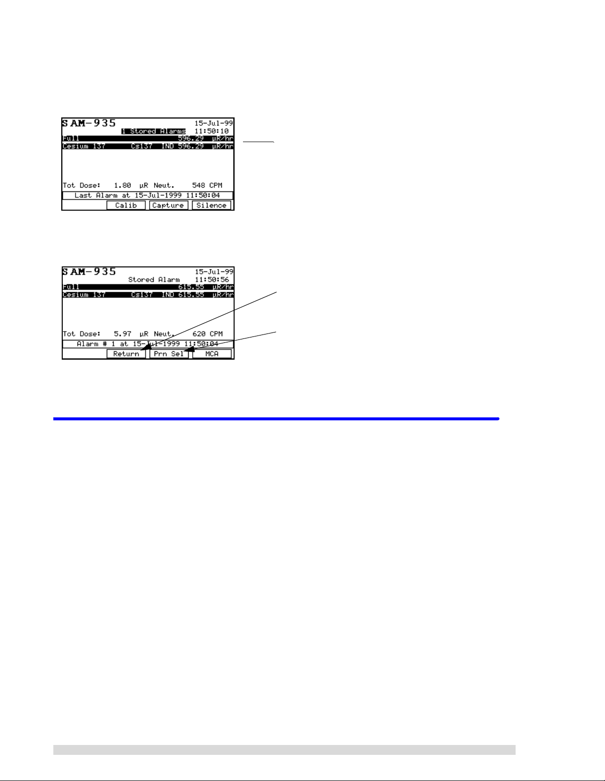
An example of the main dose rate monitoring screen is shown below:
}
If there are stored alarms, you can review them by pressing the ← or → arrow keys from the main
Surveillance monitori ng scr een:
If other display modes are enabled, they will show up as options under the F1 function key. Display modes
are discussed in Section 5.
The dose rate units are recorded in metric abbreviations
of Sievert (Sv) or REMs (R ).
Press F2 to return to Surveillance mode and take more
readings.
Press F3 to print the stored alarm(s); see Section 7.1
for more information about this report.
3.2 Recalibration Procedure
Follow the directions in this section to perform a complete recalibration of the SAM 935. To ensure accurate, reliable results, you should recalibrate the SAM 935:
• when you first install it. It is calibrated at the factory, but it should be recalibrated on site to ensure
reliable results. This requires only a coarse adjustment and background spectrum, and can be
done with the one-button quick calibration on the main screen (F2). See Section 4.2.1 for details.
• whenever the temperature changes drastically (such as moving from indoor to outdoor monitoring). This requires only a coarse adjustment and background spectrum, and can be done with the
one-button quick calibration (F2). See Section 4.2.1 for details.
• if you change the type of detector you are using with it; this requires a coarse and fine calibration.
• If you perform a memory reset.
You perform this 3-step recalibration process from the
This calibration method automatically adjusts hardware parameters such as high voltage and amplifier
gain to achieve a proper energy calibration for the system. The quick calibration method described in Sections 1.2.2 and 4.2.1 does not.
1. Press the U
TIL key to bring up the Utilities menu.
Calibrate Area Monitor
option in the Utilities menu.
10 SAM 935™ Instruction Manual
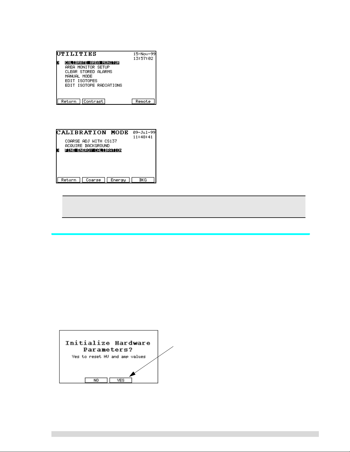
2. Select
Calibrate Area Monitor
from the menu:
The 3 steps needed to perform a recalibration are listed in the order they should be done:
Before beginning the rec alibration process, mak e sure the proper detector is selected using
the
Select/Edit Detector
function under the UTIL key.
3.2.1 Automatic Coarse Calibration
This process requires only a Cs137 source. It may take up to several minutes depending on the activity of
the source.
1. Press the U
2. Select
3. Select
4. If your SAM 935 was factory-calibrated, you will see the message below. Press Y
time you do a coarse calibration; this will cause the SAM 935 to start its hardware adjustment algorithm from scratch. Answer N
bration process quicker) .
5. Point the right front corner of the detector at the Cs137 standard (of approximately 0.5 to 2.0 µCi)
and press S
TIL key.
Calibrate Area Monitor
Coarse Adj With Cs137
TART (F2) to begin data acquisition.
from the list.
from the list, or just press F2.
O (F2) after the initial coarse adjustment (this will also make the cali-
ES (F3) the first
Answer Yes the first time you do a coarse calibration;
answer No thereafter.
SAM 935™ Instruction Manual 11

The spectrum being measured will be displayed as it develops, and if everything is connected correctly, you should be able to watch the spectrum resolve. After each adjustment attempt, a tone
will sound to indicate that the SAM 935 is still adjusting itself. For details about the coarse adjustment, refer to Section 5.6.1.
6. When the adjustment is complete, the two Cs137 peaks will be highlighted, the unit will beep three
times, the
able. At this point, the display should look like the one shown below. If not, press C
check that you have the correct source and retry the operation. If everything is correct, press S
Adjustment Co mp le te
message will appear, and the SAVE (F4) function key will be avail-
ANCEL (F1) and
AVE
(F4) to save the new hardware parameters in memory.
If you experience difficulty during the coarse calibrat ion, press CAN CEL (F1) and the n select
Calibrate Area Monitor
from the
Utilities
menu to start over.
Press Save to finish the coarse calibration.
After you save the coarse calibration adjustment, the SAM 935 will return to the Calibration menu. Continue with calibration by taking a background spectrum next.
3.2.2 Acquire a Background Spectrum
To get accurate identification results, a background spectrum should be taken frequently, and it must be
collected in the same physical location where the monitoring will occur. The background is very important
because it is the point of reference against measured activities.
A new background spectrum should be acquired whenever the ambient background changes, i.e., if the
instrument is moved to a new location or if a patient having received a radionuclide dose enters or leaves
the vicinity. A background spectrum is also required before doing the more accurate fine energy calibration. Background spectra can be acquired at any point. After one week, the SAM 935 will require that you
take another background spectrum.
1. At the Calibration menu, select
2. A background spectrum may not be taken without a prior coarse adjustment. If this is attempted,
the SAM 935 will ask whether you wish to perform the adjustment first. If so, press F3 to perform
the coarse adjustment.
Acquire Backgroun d
Press F2 (Util) if the coarse calibration is not required.
This will take you to the Utilities menu where you can
choose Calibrate Area Monitor to do the background
spectrum.
and press ENTER, or just press F4.
Press F3 (Adjust) if you have not performed a coarse calibration yet. The SAM 935 will complete the coarse
adjustment before resuming acquisition of the background spectrum.
3. Remove all sources from the vicinity of the detector.
12 SAM 935™ Instruction Manual
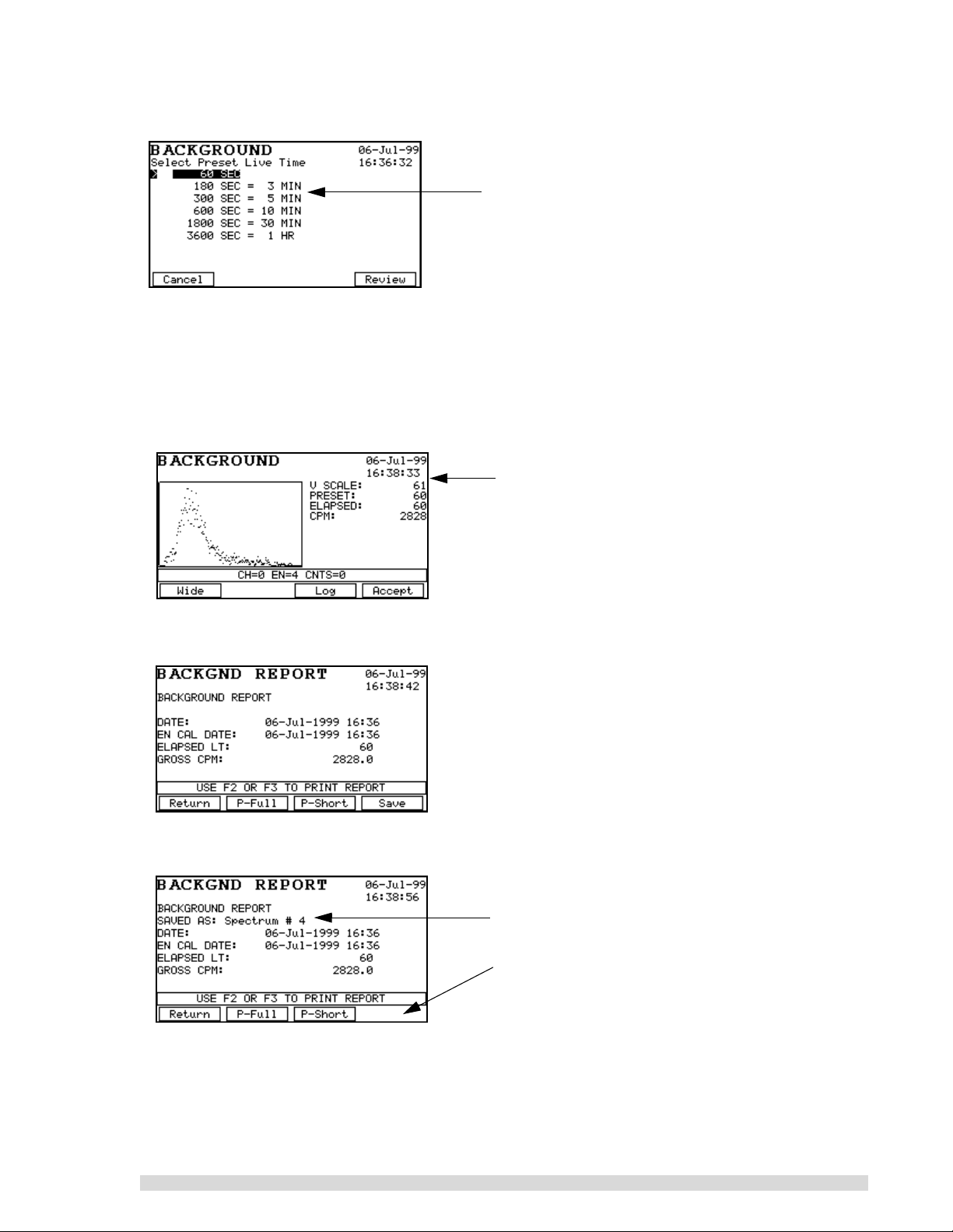
4. The Preset Live Time screen will appear as shown below. Select a live time for background collection and press E
NTER:
For most SAM 935 operations, a collection period of
180 or 300 seconds is generally adequate.
Acquiring a background spectrum takes only a few minutes, depending on the live time preset
selected. For the error in the background spectrum counting statistics to be small compared to the
spectrum of the unknown, the live time preset of the background spectrum should be large compared to that of the unknown spectrum.
5. Once a live time has been selected, the SAM 935 enters the acquire mode for background spectra. Press S
TART (F2) to begin the data acquisition. Data will appear on screen, and the Elapsed
Time will begin counting off:
When the elapsed time matches the live time preset,
the SAM 935 will beep to indicate that data acquisition
is complete. This is a good example of what a background spectrum should look like when complete.
6. Press A
CCEPT (F4), and the SAM 935 will generate a report that can be reviewed on screen and
printed:
7. Press S
AVE (F4) to save the background spectrum, if desired. This will allow the background spec-
trum to be uploaded to a remote computer if needed.
The Background Report will show you when the spectrum has been saved.
Notice that the Save (F4) function goes away after saving the spectrum.
You may also print the report if needed.
8. Press R
ETURN (F1) to leave the background reading. The MCA display will appear. Press Exit, and
the SAM 935 will return to the Calibration menu. Continue with the fine energy calibration.
For more information on the background mode, see Section 5.5.
SAM 935™ Instruction Manual 13
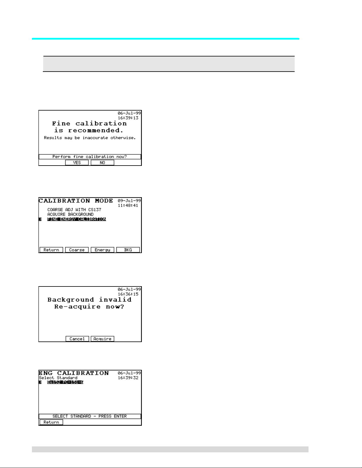
3.2.3 Fine Energy Calibration
Always perform a fine energy calibration if the external detector is changed.
If the SAM 935 has not been previously fine energy calibrated with a multi-line standard such as Eu152,
you will see the message shown below. If no Eu152 source is available, enter the three coefficient numbers as described in Section 3.2.4.
1. Press F2.
2. Select
3. If you have not taken a background spectrum recently, or have not taken one since the last coarse
adjust, you will be forced to do so now. If it’s needed, you will also be forced to do a coarse adjustment before the background reading.
4. You will be presented with a list of isotopes. Select the Eu152 standard from the list and press
E
Fine Energy Calibration
NTER:
from the Calibration menu, or just press F3.
14 SAM 935™ Instruction Manual
If you are using another standard that does not match one in this list, you will have to define it in
the Calibration Standards library. See Section 6.6 for instructions on how to define calibration standards.
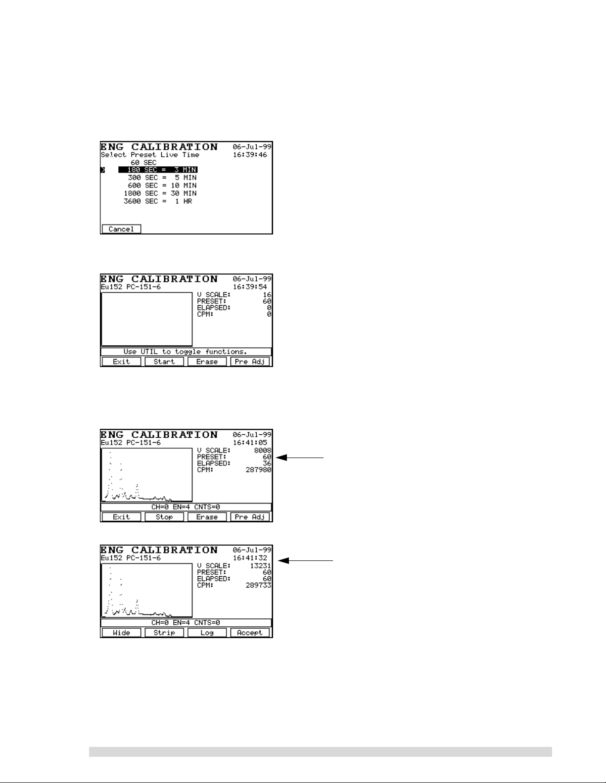
5. Now select a preset live time: If your Eu152 source is between 0.5 and 2 µCi, select a time of 180
seconds. If higher or lower activity, make an appropriate adjustment in count time.
6. Place the standard in front of the detector and press S
TART (F2).
7. When the SAM 935 beeps to indicate that data acquisition is complete, check the spectrum to verify you have counted the correct standard (i.e., about ten peaks covering nearly the entire energy
range), and if so, press A
CCEPT (F4).
Example of a fine energy calibration in progress.
Note how the function keys change in this screen
versus the next one.
Example of a completed fine energy calibration.
Press Accept (F4) after reviewing.
SAM 935™ Instruction Manual 15
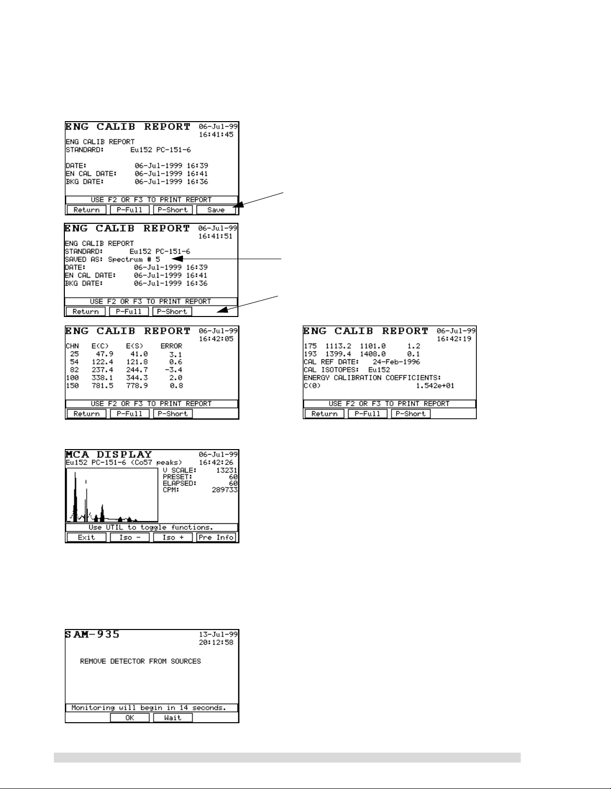
8. The calibration report will appear on the display after you accept the calibration; scroll through it
using the arrow keys to see all of it. The SAM 935 should find seven peaks and the energy errors
th
(4
column) should be in the range ±5 keV. Use the arrow keys to see the details of the report or
print short or long versions using the P-F
ULL and P-SHORT keys.
Press F4 to save the fine energy calibration, if
desired. This allows the fine calibration to be
uploaded to a PC if needed.
The Energy Calibration Report will show you when
the spectrum has been saved.
Notice that the Sav e (F 4) function goes away after
saving the spectrum.
9. When you press R
ETURN (F1) to leave the energy calibration report, the spectrum will display
10. Remove the Eu152 source from the vicinity of the detector.
11. Press E
XIT (F1) to leave the spectrum display; press RETURN (F1) once more to leave the
Calibration menu.
12. You will be prompted to remove the Eu152 source from the vicinity of the detector. The SAM 935
will begin its automatic countdown to begin dose rate monitoring:
16 SAM 935™ Instruction Manual

3.2.4 Calibration with Three Coefficients
To enter the energy calibration factors manually, the factors from a previous live energy calibration for this
unit and matching detector must be available. These numbers can be found on the printout normally done
at the end of a live energy calibration. Alternatively, the numbers can be those recorded earlier from a previous manual calibrati on with the thr ee coe fficients.
1. Press the U
Setup
2. Do NOT change anything in this screen. Press C
TIL key to bring up the Utilities menu. Use the arrow keys to select
. The first screen is the Energy Match Window:
ANCEL (F1) 10 times until you see the question
Analysis Tools
SET FINE ENGY COEFF?
3. Press Y
ES (F2).
The next three screens are standard number entry screens. Change the factors as needed. On
each screen, when the correct value is shown, press E
NTER.
4. Return to the normal operating screen.
3.3 Configure Dose Rate Units and Trigger
Because the SAM 935 operates in Surveillance mode by default (also called dose rate monitoring), configure the Dose Rate Units and Dose Rate Trigger options in the Monitor Setup menu:
1. Press the U
TIL key to bring up the Utilities menu.
SAM 935™ Instruction Manual 17

2. Select
Area Monitor Setup
through the setup screens:
. The Setup menu takes up several screens; the arrow keys will scr oll
Select
Dose Rate Units
measurement.
to choose the units of
3. Use the arrow keys to highlight
Select Dose Rate Units
and press ENTER.
4. Select the units of measurement you want to use when monitoring: F2 for REMs per hour (R/hr) or
F3 for Sievert per hour (Sv/hr). The message line above the function key labels tells you the currently selected units.
5. The display will immediately return to the Monitor Setup menu. Select
Select Dose Rate Trigger
from the menu:
18 SAM 935™ Instruction Manual

The value shown on this screen is the alarm trigger; an alarm will be generated and saved whenever any monitored target exceeds this value:
Allowable range is 0.001 to 999.999 in units of mR/hr or
mSv/hr.
6. Use the arrow keys to move from digit to digit, and to increase or decrease the highlighted value.
Press E
7. Press R
NTER to save the change.
ETURN (F1) until you are out of the Utilities menu and back to the Surveillance monitoring
screen.
If the SAM 935 is operated in another mode (Monitor or Detail), you may want to configure other Setup
options. See Section 6.1 for more information about the other options.
3.4 Dose Rate Calibration
To perform a Dose Rate Calibration, select
1. Select
Calibrate Dose Rate
from the menu and again press ENTER:
Area Monitor Setup
from the Utilities menu. Press ENTER.
The current value will be 1.00 if no Dose Rate Calibration has been done before. At this point, you
may either press E
DIT (F3) to enter the previously determined calibration factor or CALIB (F2) to
calibrate the unit with a10 µCi Cs137 source whose calibration date and activity are known.
2. Press Calib. This screen will time out after about 10 seconds or when you press E
NTER:
3. The next screen is a standard number input screen for the user to input the activity of the calibration source. Press E
NTER when correct:
4. The next screen is a standard Date edit screen. Key in the calibration date of the Cs137 standard.
Press E
NTER when correct:
5. The next screen prompts you to place the source 20 cm away from the end of the detector. 20 cm
is equal to 7.87 inches. Press OK (F2) when ready to start the calibration run:
6. When the calibration is complete, a screen showing the new calibration factor is presented. Write
this number down for future use in case the instrument is reset and the calibration source is not
available.
7. Return to the normal operating screen.
See Section 6.1.5 for more details.
SAM 935™ Instruction Manual 19

4. Operating the SAM 935
If the proper procedures are followed, the SAM 935 will give an outstanding performance in monitoring
your radiation environment. The key to optimum performance is establishing a routine for measurement
that guarantees the system is operating correctly and is properly calibrated.
To get consistent results, it is important that the system be stable thermally. In the field, this can present a
real problem if the temperature is varying rapidly. The SAM 935’s electronics are very stable against tem-
perature variations; however, NaI detectors exhibit a gain shift of up to two percent per degree Centigrade.
You can compensate for temperature drifts in the detector by periodically doing a quick calibration (F2 in
the main display).
If you need help navigating the SAM 935 software or using the front panel controls, see
Section 4.6.
4.1 Recommended Daily Operating Procedure
As long as you use the same detector with samples in the same geometry, your daily routine can be quite
simple. Each day we recommend that your work be organized as follows:
1. Power on the SAM 935. If prompted to do so, calibrate the instrument.
2. Measure each sample, spectra will be saved to memory as you go.
3. If the temperature fluctuates, perform the quick calibration adjustment periodically. (Press F2 while
in any of the three acquisition screens.)
4.2 Powering the SAM 935 On
1. Power on the SAM 935 using the On/Off push button on the front panel, located behind the sliding
door. It will automatically begin its self-test. A successful self-test will look something like this:
Note the battery condition here.
Note the type of detector(s) installed here.
20 SAM 935™ Instruction Manual

2. If you do not have an internal NaI detector, the SAM 935 will prompt you to check the cabling to the
detector after it completes the self-test. Check that any cables are properly connected and then
press OK (F2) to start monitoring.
Check the cabling to the detector and press OK
(F2) if it is acc eptab le. If it is not, you can press W a it
(F3) to delay the auto-start another 5 minutes.
After the self-test has run, the SAM 935 will wait 5 minutes and then start up, ready for operation. You can
also press OK (F2) to immediately begin operation. Press W
When the SAM 935 is ready for operation, the dose rate monitoring screen will appear:
AIT (F3) to delay startup for another 5 minutes.
The dose rate analysis displays isotopes in dose rate units (rather than the confidence levels used by the
Monitor mode). The different modes of operation are explained in Section 5.
An example of SAM 935 dose rate screen as it is actively monitoring isotopes is shown below:
}
The electronics in the SAM 935 stabilize approximately 10 minutes after power is turned on. However,
tests with NaI detectors indicate that some detectors require as much as 2 hours to fully stabilize, especially if the detector is cold. Determine how much time is needed for stable operation, and then be consistent in the elapsed time between power-up and when you start calibration.
The dose rate units are recorded in metric
abbreviations of Sievert (Sv) or REMs (R).
SAM 935™ Instruction Manual 21

4.2.1 Quick Calibration Adjustment
After the self-test, the SAM 935 may prompt you to run a quick calibration adjustment before going to the
dose rate monitoring screen:
Calibration required means this is the first time the
SAM 935 has been powered up, or some important
setting changed that requires calibration. Note that
your two choices are to perform the calibration adjustment (F3) or to enter the Utilities menu to adjust the
instrument settings (F2).
-
OR
-
The calibration recommended prompt appears when
a calibration has not b ee n performed in over a week.
Note that your two choices are to perform the cal ibra tion adjustment (F3) or to continue to monitoring
mode without performing the calibration (F2). If you
choose to skip the calibration, the monitoring results
may not be reliable.
1. Press the A
DJUST (F3) button.
2. You will be prompted to place the Cs137 standard in the detector. (Point the right front corner of
the SAM 935 at the standard.)
Press F2 to immediately begin the coarse adjustment, or wait for the 15-second countdown to
elapse.
The spectrum will bed displayed on screen as it
resolves. When the coars e cal ib ration is complete, the S
AVE (F4) function key will appear.
3. After the SAM 935 has finished its coarse calibration, it will beep twice and give you the opportunity to take a background spectrum:
If you do nothing, the SAM 935 will skip the background reading an d enter its mon itoring mo de after
a preset 15-second delay.
Press Wait (F3) to restart the 15-second delay if
you need more time to remove the source.
22 SAM 935™ Instruction Manual

If the SAM 935 detects that the background reading is unusable or non-existent, it will present this
screen, which
requires
you to take a background reading:
Remove the Cs137 standard and press F2 to
immediately begin the background reading.
4. To take the background reading, first remove the Cs137 standard from the vicinity of the detector.
Then press B
KG (F2) to begin acquiring the background spectrum.
5. The automatic background adjustment will take 1
minute (the factory setting); the spectrum will be displayed on screen as it resolves:
6. When the calibration adjustments are done, the dose rate monitoring screen will appear and you
can begin taking samples:
If the SAM 935 i s unable to coarse ad ju st, i t wi ll t ell y ou . ( You may notice that th e p eak is to o
far to the right of the screen or off the screen because the high voltage and gain are too high.)
If you see this message, it usually means the energy range was too high before the quick calibration was started. Press C
to reset hardware values, ans wer Y
ANCEL and go to the Utilities menu to calibrate. When prompted
ES. Perform a coarse calibrati on a nd ba ck gr ou nd reading;
the fine calibration does not need to be redefined if the last one was valid.
4.3 Powering the SAM 935 Off
Whenever the SAM 935 is turned off, all information is saved in battery-backed-up RAM. This allows you to
start up again without loss of calibrations and other information. Note that if the internal lithium battery has
failed, the self-test display will indicate the problem.
1. Power off the SAM 935 using the On/Off push button on the front panel, located behind the sliding
door.
SAM 935™ Instruction Manual 23

4.4 Taking Readings in Surveillance Mode
The monitoring display of the SAM 935 will look different depending on the operating mode of the instrument. The default operating mode for the SAM 935 is Surveillance mode, also called dose rate monitoring.
In Surveillance mode, the SAM 935 continuously takes readings and analyzes isotopes in dose rate units,
saving and reporting any alarm conditions (when the dose rate exceeds the dose rate trigger).
1. The blank Surveillance monitoring screen will look like this:
2. Point the detector at the sample to be monitored and watch the front panel display:
3. Press C
when you pre s s C
will again have the choice to capture it or not.
An alarm condition is triggered when any of the items being monitored exceeds the trigger level for at least
the On Hysteresis number of sample intervals. The trigger level can be dose rate or peak-to-background
ratio. The alarm condition continues until the radiation level drops below the trigger level for at least the Off
Hysteresis number of samples.
During an alarm, the SAM 935 acquires and stores an integrated spectrum for the entire alarm period. The
alarm level displayed for each monitored item is the highest level encountered during any time interval of
the alarm. This allows the SAM 935 to detect a transient trigger on one isotope that might otherwise be
masked by a longer alarm generated by another isotope.
If you suspect that isotopes are being reported incorrectly, you may want to temporarily
increase the sample count time to get more stable readings. If this does not resolve the issue,
re-do the coarse and fine calibrations. Note that if the Cs137 source is too “hot”, or if it is positioned at a distance from the detector, the X-ray peaks will not register correc tly. The SAM
935 may think it is ca librated wit hout using the X-ray peak. T he other ca use of incorrec t isotope reporting may be poor detector resolution, or the parameters in the Analysis Tools Setup
(energy match windows) may be adversely affecting the readings.
APTURE (F3) to save the currently displayed reading. The current alarm will be terminated
APTURE. If the condition continues to alarm, a new alarm will be created and you
24 SAM 935™ Instruction Manual

4.5 Reviewing Alarms
The SAM 935 can store over 250 alarm events. Each stored alarm consists of a spectrum and all of the
information necessary to analyze the spectrum. Stored alarms can be viewed by using the ← and → arrow
keys:
Review stored alarms by pressing the ← or → arrow keys from the main Surveillance monitoring screen:
• From the main display, press the ← (left) arrow key to display the previous (most recent) alarm.
• From the main display, press the → (right) arrow key to display the first stored (oldest) alarm.
Once you are in review mode, the ← and → arrow keys move from alarm to alarm in a circular fashion as
shown in this example below:
Main 935 Display
Press
Press
(most recent) Alarm #4
Press
Alarm #3
Live (current) alarm
Press
Press
• At any time in the review process, pressing the R
ETURN (F2) key will bring you back to the main
Press
Press
(oldest) Alarm #1
Press
PressPress
Alarm #2
monitoring screen.
• Press P
RN SEL (F3) to print the selected stored alarm through the serial port. An example of this
printout is shown on page 59, Section 7.1.
• Press MCA (F4) to enter the Manual mode of operation; see Section 5.4 for more information.
A Memory Full message will appear on screen if the stored alarms approach the memory capacity. When
memory is full, the earliest alarms will be discarded to make room for the most recent alarms being stored.
If you see the Memory Full message, you can download the stored alarms to a remote computer, if
desired, and then
Clear Stored Alarms
in the Utilities menu.
SAM 935™ Instruction Manual 25

4.6 The SAM 935 Interface
This section explains the SAM 935 interface controls.
4.6.1 The Front Panel
The front panel of the SAM 935 has an LCD screen where instructions and data are displayed. At the top
of each screen is a mode name (e.g., “Utilities” or “SAM-935” in the example below). In some screens, a
description of the current step appears below the screen mode name (e.g., “Edit Isotopes” or “Auto
Adjust”).
Screen mode
Message line
Function keys
name
Function key
labels
Utilities key
In the middle of the screen, just above the function key labels, is a message line, which displays important
information about the current state or mode. In some screens (such as Edit Isotopes), it simply provides
directions.
Below the screen are two rows of keys. The first row of keys, F1 through F4, control a variety of functions
throughout the software. The current function of each of these keys varies according to the screen that is
displayed: the function labels are displayed at the bottom of the screen directly above the corresponding
function key.
A row of arrow keys below the function keys are used to select items from lists in some screens and to
move a software cursor in others.
Finally, the U
TIL key provides access to utility programs (see Section 6), and the ENTER key is used to
make selections and to indicate when certain tasks have been completed.
26 SAM 935™ Instruction Manual

4.6.2 Function Keys
The labels just above the function keys show what function each key will perform.
Some function keys perform a single defined function, such as R
when available. R
ETURN is used to exit from the current screen when done. CANCEL is used to abort from a
ETURN, which always appears over F1
step, typically without saving any of the changes that might have been made.
Other function keys, such as E
pressed (E
NABLE becomes DISABLE, for instance).
NABLE, are toggles; the meaning of the button will change each time it is
4.6.3 Scrolling Through Long Menus
Many of the screen modes allow (or require) you to select an
item from a list of alternatives, such as the list of isotopes
shown here. To scroll through this list, use the ↑ and ↓ arrow
keys to highlight an item, and the E
NTER key to select it.
Some lists are too long to be displayed on one screen—simply keep scrolling with the down arrow key. When you scroll
down past the last item displayed, it will jump to the next
screen of the menu. Or use the ← or → arrow keys to more
quickly turn to the previous or the next menu screen,
respectively.
4.6.4 Editi ng Inst ruct ions
A few screen modes require a text description or a numerical value to be entered. Since the SAM 935 keyboard has only 10 keys, entering this information requires some care. However, all data in the SAM 935 is
battery-backed-up so most information of this type will have to be edited only once during the life of the
instrument.
When new entries are created, the SAM 935 may automatically enter a default value, such as “Name”. You
will want to delete this entry before entering your data.
SAM 935™ Instruction Manual 27

Editing Text
An example of text editing is shown in this Edit Standard Name screen. The current value of the text is
shown in highlight on the screen.
1. Each character must be entered by highlighting it in the grid (the letter “A” is highlighted here)
using the arrow keys, and then pressing S
ELECT (F2). The selected character(s) will appear in the
highlighted field.
2. To edit the text in the highlighted field: press D
ELETE (F3) to delete a character; press SPACE (F4)
to enter a blank space.
3. When you’ve finished editing the text, press E
saving the changes, pres s C
ANCEL (F1). Y ou will be asked to confirm the cancel.
NTER to save it. If you wish to cancel the edit without
Editing Numbers
The edit radiations screen is shown as an example of editing numerical data in the system. Editing numerical data is similar to editing text, but is restricted to the few characters that might appear in a floating point
number (including exponents). As with text, the current numerical value is shown in highlight on the
screen.
1. To clear the entire value in the highlighted field: press C
2. To backspace and delete one value at a time, press B
LEAR (F4) to delete the value.
ACK (F3).
3. To enter a new value, use the arrow keys to highlight it in the list at the top of the screen (the number “0” is highlighted here), and then press S
ELECT (F2). The selected character(s) will appear in
the highlighted field. Numbers can be entered in fixed (xxx.xx) or floating (x.xxxe±xx) format.
4. When you’ve finished editing the number(s), press E
without saving the changes, press C
ANCEL (F1). You will be asked to confirm the cancel.
NTER to save it. If you wish to cancel the edit
Other screens for editing numerals use the ← and → arrow keys and the ↑ and ↓ arrows to change the
value:
1. Edit one field at a time. To move to the next character, use N
ous character, use P
REV (F1) or ←.
2. Increase the value of the highlighted character using the I
with the D
EC (F4) key or ↓.
EXT (F2) or →. To move to the previ-
NC (F3) key or ↑. Decrease the value
28 SAM 935™ Instruction Manual

4.6.5 The Utilities Screen
Press the UTIL key from the main screen to bring up the Utilities menu, which has more items than will fit on
one screen:
Use the ↑ and ↓ keys to scroll through the list, and the ← and → keys to move to the next page. You can
also get to the end of the list quickly by pressing the ↑ key at the top of the list. Y ou can directly access
three of the choices, or exit, using the function keys:
R
ETURN F1 Returns to the main menu.
ONTRAST F2 Allows you to adjust the screen display contrast.
C
R
EMOTE F4 Switch to remote (external computer control) mode.
All of the utilities are discussed in detail in Section 6.
SAM 935™ Instruction Manual 29

5. SAM 935 Modes of Operation
The SAM 935 default operation is the Surveillance mode, also called dose rate monitoring. Dose rate monitoring is the focus of this manual. In addition, options in the Utilities menu allow you to operate the SAM
935 in Monitor, Detail, or Manual modes. Y ou toggle the modes of operation from the Utilities menu:
Monitor Setup
:
Select Display Modes
:
The default setup for the SAM 935: only the
Surveillance operating mode is enabled.
This example shows all operat ing modes enabled.
Area
Press F2 to enable or disable Monitor mode, also called peak-to-background monitoring.
Press F3 to enable or disable Detail mode.
Press F4 to enable or disable the Surveillance mode of operation; this mode is enabled by default.
A Manual mode of operation is also available as a separate selection in the Utilities menu. This mode of
operation is described in Section 5.4.
5.1 The Surveillance Mode of Operation
The majority of SAM 935 operations begin from the main Surveillance monitoring screen shown below:
Date and time display will change to Battery Low
message when the battery pack needs to be
recharged or replaced.
30 SAM 935™ Instruction Manual

The Surveillance screen when alarms have been triggered looks something like this:
The function keys on the Surveillance monitoring display are:
•C
ALIB (F2) performs the quick, one-button calibration adjustment that is described in Section 4.2.1
and in the Quick Reference.
•C
APTURE (F3) saves the currently displayed reading. The current alarm will be terminated when
you press C
APTURE. If the condition continues to alarm, a new alarm will be created and you will
again have the choice to capture it or not.
•S
ILENCE (F4) turns off the audible alarm. If there are no alarms currently going on, then the F4
Function key bec omes ALM TEST. Pressing ALM TEST will activate the alarm indicators for test pur-
poses; each press of the A
LM TEST key will cause the alarm indicators to turn on for 5 seconds.
• When in the alarm review mode, the F2, F3, and F4 function keys become R
ETURN, PRN SEL, and
MCA, respectively. These functions are described above in Section 4.5.
5.2 The Monitor Mode of Operation
The primary element of the monitor mode display is the alarm meter. This “graphics equalizer” type of bar
graph shows a continuous readout of the signal strength associated with each trigger being monitored.
The display is drawn in terms of sigma’s above background.
For each trigger, a dashed line shows the alarm threshold for that trigger. When an alarm occurs, the word
Alarm and the alarm value will be displayed next to the bar graph. Once an alarm has occurred, the word
Alarmed will flash at the top center of the screen with the number of stored alarms immediately below it.
The time of the alarm will be displayed in the message line immediately below the bar graphs.
The order in which the bar graphs are presented changes with every measurement interval: the most
intense alarm measured during the interval is presented first; least intense is shown last.
The function keys on the main monitor display are:
•D
ETAIL (F1) switches to the Detail mode, if it is enabled. This mode is described in the next section.
ALIB (F2) performs the quick, one-button calibration adjustment that is described in Section 4.2.1
•C
and in the Quick Reference.
SAM 935™ Instruction Manual 31

•CAPTURE (F3) saves the currently displayed reading. The current alarm will be terminated when
you press C
APTURE. If the condition continues to alarm, a new alarm will be created and you will
again have the choice to capture it or not.
•S
ILENCE (F4) turns off the audible alarm. If there are no alarms currently going on, then the F4
function key becomes A
poses; each press of the A
LM TEST. Pressing ALM TEST will activate the alarm indicators for test pur-
LM TEST key will cause the alarm indicators to turn on for 5 seconds.
• When in the alarm review mode, the F2, F3, and F4 function keys become R
ETURN, PRN SEL, and
MCA, respectively. These functions are described above in Section 4.5.
5.3 The Detail Mode of Operation
In Detail mode, the actual spectrum being acquired is displayed. If an alarm is in progress, the displayed
spectrum is the accumulated spectrum for the entire alarm:
The function keys on the detail display are:
URVEIL (F1) will switch to the Surveillance mode of operation.
•S
•C
ALIB (F2) performs the quick, one-button calibration adjustment that is described in Section 4.2.1
and in the Quick Reference.
•C
APTURE (F3) saves the currently displayed reading. The current alarm will be terminated when
you press C
again have the choice to capture it or not.
•S
ILENCE (F4) turns off the audible alarm. If there are no alarms currently going on, then the F4
function key becomes A
poses; each press of the A
APTURE. If the condition continues to alarm, a new alarm will be created and you will
LM TEST. Pressing ALM TEST will activate the alarm indicators for test pur-
LM TEST key will cause the alarm indicators to turn on for 5 seconds.
• When in the alarm review mode, the F2, F3, and F4 function keys become R
ETURN, PRN SEL, and
MCA, respectively. These functions are described above in Section 4.5.
5.4 Manual Mode
Manual mode is a sophisticated, alternate mode of operating the SAM 935. Use this mode to acquire data;
view and edit hardware parameters; set, clear, and edit regions of interest (ROIs); and perform qualitative
analyses.
1. Press the U
the Utilities menu
32 SAM 935™ Instruction Manual
TIL button and choose
Manual Mode
from

The Manual mode screen will appear:
Note this message: Pressing the Util key in Manual
mode toggles a different set of function keys; see
Section 5.4.3.
2. Begin taking readings. When a spectrum is displayed, the message line will normally display the
cursor readout. Displayed are the cursor channel (CH), the energy (EN, if calibrated), and the
counts in the cursor channel (CNTS).
3. If everything is correct, press A
CCEPT. The spectrum will be analyzed and the results displayed on
the screen. You can print either short or long versions of the analysis report by using the function
keys on the report screen. The long version includes: 1) system setup information, 2) a graphical
printout of the spectrum, 3) detailed peak analysis, and 4) the details of the isotope cross correlation analysis. The short version of the report includes only items (1) and (3). An example of this
report can be found in Section 7.4.
4. When you exit the report screen you are back in the Manual mode screen. You can edit ROIs, take
data for longer, etc., and then press S
5. To analyze another sample, simply E
TART (F2) again to repeat the analysis.
RASE (F3) the data and start again.
The cursor can be controlled with the arrow keys. The ← and → keys move the cursor one channel at a
time along the spectrum, while the ↑ and ↓ keys move the cursor 1/16 of the spectrum at a time. The spectrum display is initially in its narrow mode, with the area at the right of the spectrum displaying a variety of
information. The initial set of information is called the “data” screen. Here the vertical scale, preset live
time, elapsed live time, and count rate in CPM is displayed. The information displayed in this area can be
changed by pressing F4. Just above the spectrum display is an area in which instructions, sub-mode titles,
or current spectrum data are displayed.
The initial set of function keys in the Manual mode have the following functions:
Exit (F1) The E
XIT key causes you to exit from the mode. Data acquisition is
stopped and nothing is saved.
Start (F2) The S
TART key begins data acquisition. Once it is pressed t he label
changes to Stop. Data acquisition can be started and stopped as many
times as desired.
Erase (F3) The E
RASE key erases the data and resets the elapsed real and live times
to zero. The key may be pressed at any time.
WARNING: NO CAUTION IS GIVEN THAT DATA IS ABOUT TO BE ERASED
Pre Adj (F4) The P
RE ADJ key changes what is displayed on the right side of the
screen to a display of the preset values of the system as shown below.
SAM 935™ Instruction Manual 33

5.4.1 MCA Presets
When PRE ADJ (F4) is selected, the presets are displayed in the data area. When the presets are displayed, the F4 function key changes to read HW A
935 has the following types of preset controls:
ON/OFF When the preset enable is set to OFF presets will have no effect. It is the
same as setting all presets to zero.
LT Pre Preset live time.
RT Pre Preset real time.
Pk Pre Preset peak count.
Int Pre Preset integral.
DJ (or HW INFO when not in Manual mode). The SAM
Note: Preset live and rea l time will be e xact, whil e in prese t peak and integ ral, the actual
values may exceed the preset slightly.
If you are in the manual MCA mode, the presets may be adjusted from this screen. Pressing the ↓ and ↑
arrows moves from preset to preset. The currently selected preset is displayed in the message line. Use
the ← and → arrows to change the value of the selected preset.
34 SAM 935™ Instruction Manual

5.4.2 Manual Hardware Adjustments
HW Adj/HW Info This key switches the information displayed in the data window to the
hardware parameters.
When HW A
data window. The F4 function key becomes a D
DJ/HW INFO is selected from the Presets screen, a set of hardware parameters is listed in the
ATA key that returns the system to the data mode.
HV Supp Displays the state of the bias voltage supply – on or off.
BIAS Current bias voltage setting. This voltage ranges from 200 to 1000 volts.
CG Amplifier coarse gain. Available values are 1, 2, 4 and 8.
FG Amplifier fine gain. Range is 1.00 to 2.55 in steps of 0.01.
LLD Low level discriminator. Range is from 0 to 105 percent of full scale in
steps of approximately 0.4%. For normal work the LLD should be set to
0.8 or 1.2.
ULD Upper level discriminator. Range is from 0 to 105 percent of full scale in
steps of approximately 0.4%. For normal work the ULD should be set to
105%.
ZERO ADC zero setting. Range is ±5% of full scale.
XFRM Conversion m ode . Th e s yst em is op t im i ze d fo r QCC (SQRT) mod e . Al l o f
the analyses should be done in this mode. Standard linear mode is pro-
vided for those who desire it.
Under manual MCA mode (the HW A
screen modes (HW I
NFO), they may only be viewed.
DJ mode), it is possible to adjust these hardware parameters. In other
SAM 935™ Instruction Manual 35

5.4.3 Manual Mode Utilities
When you are in the Manual mode display, the UTIL key has a special function: it switches to alternate sets
of function keys. When the U
set of function keys are displayed:
Wide This key changes the spectrum display so that the spectrum occupies the full width of
the display.
Strip This key displays the spectrum with the ambient background subtracted. When
pressed, the label changes to N
play to its normal (unstripped) mode.
Log This changes the display to a log display as shown above. The function key label
changes to L
TIL button is pressed while the initial Manual screen is displayed, the following
ORMAL. Pressing the STRIP key again returns the dis-
INEAR. Pressing the key again returns to linear mode.
Accept At various times the F4 key may display A
CCEPT or RETURN. When ACCEPT
is displayed, it means that data has been collected and the opportunity is given to accept it,
erase and start over, or cancel the operation. Pressing A
CCEPT causes the analysis to
proceed, and offers the opportunity to place the spectrum into the spectrum storage as
well.
Except in background mode (where there are no ROIs), pressing U
TIL again from this set of function keys
brings up the ROI editing keys shown below:
Start This key begins an ROI. Use the cursor keys to position the cursor at the desired start-
ing channel. Press S
TART. The START key will change to STOP. Now use the cursor
keys to sweep out the ROI. When the desired end channel has been set, press the
S
TOP key. As many ROIs can be set as desired. NOTE: ROIs may not overlap. If an ROI
is set over an existing ROI, the portion of the old ROI overlapped will be replaced with
the new ROI.
Clr Cur Removes the ROI in which the cursor is located.
Clr All Removes all ROIs.
From the previous set of function keys (display keys or ROI keys depending on the mode), the next press
of the U
TIL key brings up the library peak labeling function.
36 SAM 935™ Instruction Manual

The peak labeling function allows you to display the gamma lines associated with particular nuclides
superimposed on the current spectrum. This feature is available both during and at the end of data acquisition. The I
SO - (F2) and ISO + (F3) keys cycle through the list of all enabled nuclides in the nuclide data-
base. For each, the enabled lines are shown with a height proportional to the log of their intensity.
Note: he hardware controls, preset controls, and ROI controls are only functional in
manual MCA mode.
5.5 Background Mode
The SAM 935 requires that an ambient background spectrum be taken before it will allow fine energy calibration and will not perform monitoring operations without one. The procedure for taking background spectra is described in Section 3.2.2.
The background mode screen looks like this:
The initial set of function keys have the following functions:
Wide This key changes the spectrum display so that the spectrum occupies the full width of
the display.
Log This changes the display to a log display. The function key label changes to L
INEAR.
Pressing the key again returns to linear mode.
AcceptAt various times the F4 key may display A
CCEPT or RETURN. When ACCEPT
is displayed, it means
that data has been collected and the opportunity is given to accept it, erase and start over, or cancel the
operation. Pressing A
CCEPT causes the operation (usually an analysis of some kind) to proceed, and the
spectrum will be placed into the spectrum storage as well.
The ambient background spectrum is stored and then subtracted from other spectra on a channel-
by-channel basis before they are analyzed. This provides a correction for any ambient radioactivity in the
vicinity of the detector and for background from cosmic rays, etc.
Because the counting statistics in the background spectrum directly affect the uncertainty in the analyzed
spectra, it is very important that the background be counted for a long time relative to the sampling interval.
SAM 935™ Instruction Manual 37

If you are operating with a 5-second sample time (the default), a background of 180 seconds or longer is
desirable.
Once the background spectrum is taken, you are given the opportunity to review the report generated or to
print it in long or short form. Check the gross CPM displayed on the report screen carefully
conditions, you should expect this number to be between 3000 CPM and 4000 CPM.
Two of the most likely causes for high backgrounds are radioactive materials near the counter in the form
of samples or standards, or high concentrations of natural radioactive material such as K40 in the materials of the building. High background levels are sometimes associated with concrete or cement block construction. High radon levels are also a possibility. The SAM 935 has the unique ability to operate well in a
wide range of background environments.
. Under normal
5.6 Calibration Mode
Accurate calibrations are essential for the SAM 935 to give accurate results. The calibration routines provided with the SAM 935 give you the tools to accurately calibrate and to maintain the calibrations easily.
Note: Before your SAM 935 left th e factory, it was carefully calibr ated using a set of calibration sources. T hese calibrations ( stored in the battery-b acked-up memory of the system) were made with your detector and shou ld be correct. Under no rmal circumstances,
you will be able to simply use the one-button quick calibration (F2 in the main display).
5.6.1 Manual Coarse Adjust with Cs137
The primary purpose of the coarse adjust procedure is to adjust the high voltage, coarse gain, and fine
gain of the SAM 935 to put the reference peaks (32.89 and 661.66 keV) of Cs137 into known channels of
the MCA.
The coarse adjust algorithm first adjusts the high voltage of the SAM 935 and then the coarse and fine
gains to achieve this goal. When complete, the 661.66 keV line for Cs137 will be in the correct channel to
within 0.8 percent. This is close enough so that calibrations can be maintained across adjustments of the
electronics.
If the SAM 935 has been previously calibrated either by you or at the factory, a screen will appear to ask if
you want to initialize the hardware parameters. If the SAM 935 has been previously adjusted and has not
been subjected to large swings in temperature, select N
its adjustment at the existing values for the high voltage and coarse and fine gains. All parameters will be
adjusted if necessary to achieve proper calibration.
If there have been large temperature changes or this is the first time you have adjusted the SAM 935,
select Y
goes through the entire algorithm. Both will result in the same calibration; however, starting where you
were last time can be much faster. In rare circumstances such as a change of detectors, the operation may
succeed when parameters are reset when it fails keeping the original values.
During each acquisition sequence, the spectrum being measured will be displayed as it develops, and if
everything is connected correctly, you should be able to watch the spectrum resolve. The vertical scale is
shown above the spectrum, and in the message window below the spectrum, the current hardware parameters (high voltage, coarse gain, fine gain, zero) will be displayed. A vertical line (cursor) is positioned at
the target location of the 661.7 keV Cs137 line.
ES (F3). When YES is selected, the SAM 935 resets all parameters to their minimum values and
O (F2). When NO is selected, the SAM 935 begins
38 SAM 935™ Instruction Manual

After each adjustment attempt, a tone will sound to indicate that the SAM 935 is still adjusting itself. The
SAM 935 begins with the bias voltage at a minimum level and then increases it to achieve coarse agreement with the desired peak location. Once coarse agreement is achieved (or the maximum bias voltage is
reached), the coarse gain and fine gain controls are used to achieve an energy match to within 0.8 percent. A final step will adjust the zero offset. After the hardware parameters are set, a linear fit is done to the
32.7 keV and 661.67 keV lines. For some detectors, the initial parameters to the algorithm may not yield a
recognizable spectrum at first, but within a few iterations, a recognizable spectrum should appear.
The step-by-step instructions for performing a coarse calibration are in Section 3.2.1.
5.6.2 Fine Energy Calibration
The accuracy of the SAM 935’s energy calibration can be improved by using more than the two Cs137
points for fitting a quadratic equation to the channel versus energy relationship. An ideal standard for this
process would have evenly spaced peaks covering the entire range of 30 to 3000 keV. Unfortunately, no
such long-lived, single isotope standard exists. Eu152 provides a good set of peaks from 40 to 1408 keV.
Your SAM 935 has been calibrated using a multi-line standard at the factory. If you do not have a reasonable standard to repeat this process, then we recommend not changing the factory calibration. If you
decide to use the two-point linear calibration from Cs137, some isotopes may not be identified accurately.
In some cases, they will show up as unidentified dosage or lines. The largest energy errors occur in the
range of 80 to 250 keV and above 1000 keV when a two-point energy calibration is used.
The step-by-step instructions for performing a fine energy calibration are in Section 3.2.3 above. If you
know the values, you can manually enter the fine energy quadratic coefficients via the Analysis Tools
Setup in the Utilities menu; see Section 6.8.
SAM 935™ Instruction Manual 39

6. Utilities
The Utilities menu provides access to a variety of setup and database editing functions, most of which are
described in this section. These utilities are discussed elsewhere in this manual as noted:
• Calibrate Area Monitor, see Section 3.2.
• Manual mode of operation, see Section 5.4.
Functions can be selected by moving the highlight up and down with the ↑↓ keys and then pressing E
The most frequently utilized functions can be found on the function keys at the bottom of the screen.
NTER.
40 SAM 935™ Instruction Manual

6.1 Area Monitor Setup
The Area Monitor Setup menu contains several options for configuring the SAM 935 in Monitor Mode.
You can select which isotopes to monitor, how long to take samples of these isotopes, and the conditions
under which alarms will be triggered.
The Area Monitor Setup menu takes up several screens; the arrow keys will scroll through the setup
screens:
Note the password configuration option here. You
can prevent unauthorized access to the Utilities
menu by setting up password-protection.
This menu option lets you choose between the
different operating modes of the SAM 935, as
described in Section 5.
Dose Rate Units and Dose Rate Trigger are discussed in Section 3.3.
6.1.1 Set the Sample Time
The SAM 935 operates by taking short spectra and analyzing them in real time. The period of time each
spectrum is acquired is the sample time. If quick response is required, then a short sample time should be
selected. This is particularly important in cases where the radioactivity may be moving.
For dose rate monitoring, 3 to 5 seconds is typical. For isotope identification (Monitor mode), a sample time
of 1 or 2 seconds is usually adequate. The minimum sample time is 1 second.
SAM 935™ Instruction Manual 41

To change the sample time:
1. Select
2. Use the ↑ and ↓ arrow keys to increase or decrease the amount of time in seconds that each sam-
ple is acquired.
3. Press E
Set Sample Time
NTER when finished. CANCEL will exit without changing the original value.
on the Area Monitor Setup menu:
6.1.2 Select Triggers
The SAM 935 can be configured to monitor up to 22 triggers at one time. You can configure three types of
triggers:
Isotope Any isotope from the isotope library.
Full Spectrum The total counts in the entire spectrum are summed and compared to the
background.
Unknown Peak The spectrum is searched for peaks. Any peaks found that are not associ-
ated with the isotopes being monitored are tested against the trigger
requirements.
The sensitivity of each trigger can be set independently. You can also control several parameters that
affect the overall sensitivity of the SAM 935 and its ability to discriminate false-positive triggers.
To edit what triggers the SAM 935 is monitoring, choose
A scrollable list will appear. There are four types of entries: FULL, PEAK, An Isotope Name, <unused>.
Depending on the type of entry to which the cursor is pointing, the function keys will change, as shown in
the following table:
Select Triggers
and press ENTER.
42 SAM 935™ Instruction Manual

Cursor Points To F2 F3 F4
<unused>
Any Isotope
FULL
PEAK
ISOTOPE – Allows you to
select an isotope
EDIT - Allows one isot ope to
be replaced by another
DELETE the FULL trigger
from the list
DELETE – Removes the
FULL trigger from the l ist
DELETE – Removes the
PEAK trigger from the list
TRIG LVL– Allows you to
change the trigger level
TRIG LVL – Allows you to
change the trigger level
TRIG LVL – Allows you to
change the trigger level
F2, Edit an Isotope: Scroll down the list of isotopes to the isotope you wish to monitor. Press
E
NTER, and you will be returned to the Select list.
F3, Delete a Trigger: The trigger will be deleted.
F4, Change a Trigger Level: Use the ← and → arrows to select a digit; use the ↑ and ↓ arrows to
change the digit. When you’re finished, press E
NTER.
Monitor and Detail Modes Only: The strength of a trigger is measured in terms of standard deviations
above background, where the background is measured over the same region of the spectrum. For example, in the case of a full spectrum, if the number of counts per second in the background spectrum was
100, then its standard deviation would be 10. If the number of counts in a measurement period was 145
counts per second, then the net counts above background would be 145 – 100 = 45, and the reported ratio
would be 45/10 = 4.5. This would trigger an alarm if the corresponding trigger level was set to 4 or less.
6.1.3 Set the Default Trigger Levels
The factory-set default trigger levels are:
5 All Isotopes
8 FULL Spectrum
7 Unidentified Peak
Default values apply only when an item is added to the list of triggers being monitored.
To change the default trigger levels:
1. Select
for the type of default being set (Iso, Full, or Peak) and
press E
2. Use the ← and → arrow keys to select a digit; use the
↑ and ↓ arrow keys to increase or decrease the value.
3. Press E
changing the original value.
4. Either select another default trigger level to edit or
press E
Set Default Trigger
NTER:
NTER when finished. CANCEL will exit without
NTER to return to the Monitor Setup menu.
on the Monitor Setup menu
SAM 935™ Instruction Manual 43

6.1.4 Preventing False Alarms
The Hysteresis items in the Monitor Setup menu allow you to mask out unnecessary alarms.
One of the most common “false alarm” scenarios occurs when a burst of radiation from a cosmic ray
causes a very short-term pulse of counts. To prevent this type of event from triggering an alarm, the SAM
935 has the ability to require that consecutive sample intervals all exceed a trigger level. Testing has
shown that false triggers can be almost entirely eliminated just by requiring that two consecutive time intervals exceed trigger levels. You do this by configuring an On Hysteresis.
Hysteresis refers to the lag time between a cause and its result. On Hysteresis marks the start of a trigger
event, while Off Hysteresis determines how a trigger event is ended.
1. Select
2. Use the ↑ and ↓ arrow keys to increase or decrease the value. This value will be the consecutive
sample intervals that must be exceeded before an alarm will be triggered.
3. Press E
Another problem that can occur when the radiation source is very close to the trigger threshold is the generation of a stream of trigger events. The Off Hysteresis setting can help in this case.
Consider the case where the radioactive source is at a level where 80% of the time a trigger is generated.
This is always a possible situation since, even with a constant source, there is statistical variation in the
count rate.
In the example below, an X represents a trigger and a period represents a non-trigger. Consecutive triggers are recorded as a single event. Thus, a source with an 80% trigger rate passing by might look like:
Set On Hysteresis
NTER when finished. CANCEL will exit without changing the original value.
on the Monitor Setup menu:
Sample Interval Results........XXX.XX.XXX.X.XXX.XX.X.XX.XXX.............
On = 1, Off = 1 111 22 333 4 555 66 7 88 999 (9 events)
On = 2, Off = 1 11 2 33 44 5 6 77 (7 events)
On = 1, Off = 2 1111111111111111111111111111 (1 event)
With an On Hysteresis of 1 and an Off Hysteresis of 1, the events generated would be as repre-
sented by the second line above. Note that 9 separate events are recorded, with the repeated numbers
representing consecutive triggers that are recorded as a single event. If On Hysteresis is increased to 2
and Off Hysteresis left at 1, then only 7 events are generated. The single-trigger intervals are eliminated.
When Off Hysteresis is set to 2, then the entire period is considered a single alarm.
44 SAM 935™ Instruction Manual

To change the Off Hysteresis:
1. Select
2. Use the ↑ and ↓ arrow keys to increase or decrease the value. This value is the number of consecutive sample intervals that do NOT exceed the trigger which will determine when an alarm condition is triggered OFF.
3. Press E
Set Off Hysteresis
NTER when finished. CANCEL will exit without changing the original value.
on the Monitor Setup menu:
6.1.5 Calibrate Dose Rate
The dose rate calibration is a single-point calibration using Cs137 to provide a calibration factor for dose
rate monitoring.
This calibration va lue is factory-set and does not need to be changed unless a memor y
reset was performed.
Any time the detector i s replaced (i.e., i f the detector is not t he one that shipp ed with the
SAM 935), you must perform the dose rate calibration procedure outlined below.
If memory is reset, you must either perform the dose rate calibration or manually enter the calibration factor. Contact the supplier to get the dose rate calibration value to enter if you do not know it and cannot perform the dose rate calibration.
1. Select
The next screen will display the current dose rate calibration value; this will be 1.00 if no dose rate
calibration has been done.
Calibrate Dose Rate
from the Area Monitor Setup menu:
SAM 935™ Instruction Manual 45

2. If you know what the value should be, press F3 to manually edit the value:
When finished, press E
OR
-
-
NTER to save the new value.
Contact your supplier if needed to get the value to
be entered manually here.
3. To perform the dose rate calibration, press F2. The SAM 935 will tell you that you need a Cs137
source of known activity and date to do this:
4. Press E
NTER.
5. Enter the activity of the calibration standard at the
next screen and press E
NTER:
6. Enter the standard’s calibration date at the next
screen and press E
NTER:
7. You will be prompted to place the Cs137 standard 20
centimeters (7.87 in.) away from the SAM 935’s detector. Press OK (F2) when you have done so.
You will see a spectrum resolve on screen as the calibration is taken.
46 SAM 935™ Instruction Manual

8. It will take approximately 1-3 minutes to finish, at which time the display will show you the new
dose rate calibration value. Record this number for future reference.
6.1.6 Configure Alarm Hardware
This utility allows you to enable and disable the keyboard beep, the internal alarm’s audio beep, and the
flashing visual alarm. Press F2 to enable or disable the currently highlighted item.
6.2 Clear Stored Alarms
This utility will clear the memory of all stored alarms and their associated spectra. Stored alarms are held in
memory until erased or until the stored alarms approach memory capacity, in which case, the earliest
alarms will be discarded to make room for the most recent alarms being stored. If you see the Memory Full
message, you can download the stored alarms to a remote computer, if desired, and then
alarms with this utility.
erase the stored
Follow the on-screen prompts to clear the SAM 935 memory of all stored alarms.
Another utility,
spectra (if they were saved).
Clear Stored Spectra
, will erase ALL spectra, including alarms, background, and calibration
6.3 Edit Isotopes
The isotopes database contains information on more than 80 isotopes. The information consists of nuclide
name, half-life in common units, units identifier, and enabled flag. The limit is 128 isotopes, so there is
room for you to add any special isotopes needed that are not in the database. The Edit Isotopes utility
allows users to add new isotopes, enable or disable isotopes, or edit an isotope’s data. The first screen of
the Edit Isotopes utility is shown below. Press R
tope or search for an isotope, use the ↑↓ keys. Only isotopes that are enabled are used by the software in
Manual MCA analyses.
SAM 935™ Instruction Manual 47
ETURN to go back to the Utilities menu. To select an iso-

6.3.1 Adding a New Isotope
To add a new isotope, press ADD (F2). A new entry will be
added at the bottom of the list. Then use the E
functions as described next to give the isotope the name and
parameters desired .
DIT and ENABLE
6.3.2 Enable/Disable Isotopes
Only those isotopes that are “enabled” are considered in searches and quantitative analysis. T o enable an
isotope, select it in the list with the arrow keys and press E
by selecting it and pressing the D
selected isotope would change to if you pressed it.
ISABLE (F3) key. Note that the label on F3 indicates what state the
NABLE (F3). An enabled isotope may be disabled
Enable/Disable Isotopes applies only to the Manual MCA mode. See Section 6.1.2 “Select Trigger” to
select isotopes for the Monitor and Surveillance operating modes.
6.3.3 Editing an Isotope
Press EDIT (F4) to edit the isotope information:
1. First the name is edited:
2. Edit the value of the half-life:
48 SAM 935™ Instruction Manual

3. Edit the units for the half-life. The available half-life units are selected from a list as shown below:
6.4 Edit Isotope Radiations
The radiations database initially contains over 280 lines. Lines may be added to existing isotopes or new
isotopes may be added with their lines. When
played. Use the ↑↓ keys to select the isotope whose lines are to be edited. Press E
tions for “Isotope” screen is now displayed.
Edit Radiations
is selected, the Select Isotope screen is dis-
NTER. The Edit Radia-
1. Either select an existing line to edit or press the A
DD key to add a new line for this isotope.
2. There are four numbers to edit for a radiation. The first is the line energy in keV.
3. After editing the energy, press E
NTER to edit the intensity for the line. Intensity is entered in terms
of gammas per 100 disintegrations.
4. Next edit the detector efficiency for the line. Normally, this field will not be edited. The efficiency
used in dose rate and monitoring calculations will be based on the detector efficiency model.
5. The final item is the Summing Correction. Unless you thoroughly understand the physics of the
nuclear decay scheme of this isotope, leave this set to the default value of 1.00.
The F3 function key toggles between the E
NABLE, DISABLE, and PRIMARY settings for each line.
6.5 Print Databases
The Print Databases utility allows you to print the nuclide and radiation information for a single nuclide with
P
RN SEL (F2) or for the entire nuclide database with PRN ALL (F3).
To print only part of the nuclide database:
1. Press F2.
2. A list of isotopes will be displayed. By default, all of them are set to “no print”. If you press E
now, nothing will print out.
NTER
3. Highlight an isotope you wish to print out using the arrow keys, and press F3 to enable it for printing. Repeat this for each isotope to be printed.
SAM 935™ Instruction Manual 49

4. When you have selected all the isotopes you want to print, press ENTER to send it to the printer.
To print the entire database, press F3.
An example of a Nuclide Database Printout can be found on page 62.
6.6 Edit Calibration Standards
Calibration standard definitions are stored in a database in the SAM 935’s non-volatile RAM. For each
standard, the SAM 935 stores a name (up to 19 characters), a standard calibration date and time, and up
to three isotopes. Each isotope is selected from the library and has associated with it an activity that is displayed in the currently selected system units for activity. There is a maximum of 128 isotopes in the library.
The lines to be used for each isotope are taken from the radiations database. Only lines that are “enabled”
are used. When your SAM 935 arrives, there will be a number of standards in the database. These standards were used at the factory to calibrate the system. If you are adding a new calibration standard, it
should have at least five lines spread over the energy range of interest.
The firmware has room for 20 standards with 5 isotopes per standard.
6.6.1 Adding a Standard
To add a standard to the library press the ADD key. The words standard name will appear at the top of the
list of standards. This can then be edited with the E
to use the D
ELETE (F3) key to erase the existing information that is highlighted.
DIT key . Note that when you first access a field you have
6.6.2 Deleting a Standard
To delete a standard, select it in the list and press the DELETE key. Exercise care, as there is no second
chance to avoid erasing the standard once the D
ELETE key is pressed.
To delete an isotope from a standard, select the standard from the menu and press Enter four times until
you see the Edit Isotopes screen (see next section). Use the arrow keys to select an isotope and press
D
ELETE (F3).
6.6.3 Editing a Standard
To edit a standard:
1. Edit the standard name.
2. Edit the standard calibration date and press E
calibrated. Next, edit the standard calibration time and press E
3. Next, a list of three possible isotopes will be displayed.
NTER. This is the date the activity of the standard was
NTER.
50 SAM 935™ Instruction Manual

4. For each isotope to be added, select an <unused> entry and press EDIT (F4).
5. The Select Isotope screen will appear as shown below. Use the ↑↓ keys to highlight the desired
isotope. Press E
NTER to select it and return to the previous screen.
6.7 Select / Edit Detector
SAM 935s ship with an internal or optional external detector that is already set up at the factory. If you want
to review information about the detector, you do so with this utility:
1. Press the U
TIL key on the front panel of the SAM 935 and choose
Select/Edit Detector
from the
Utilities menu:
2. A screen will appear that lists all supported SAM 935 detectors.
3. Use the ↑ and ↓ keys to highlight the detector you will be using and press E
NTER.
The SAM 935 depends on a theoretical model of the detector being used. The parameters for this model
are contained in a detectors database. The correct parameters for all supported SAM 935 detectors are
preloaded in the database.
4. Press Edit to see the detector definitions.
SAM 935™ Instruction Manual 51

Each detector has the following parameters associated with it:
Name: The name for this detector.
Diameter: Diameter of the actual NaI crystal in cm.
Thickness: Thickness of the detector in cm.
Samp Dist: Distance from the sample to the detector surface. For well-type detectors, enter zero.
Window 1: First detector window. For most NaI detectors, this will be aluminum. The thickness is
in cm.
Window 2: Second detector window thickness in cm.
Window 3: Third detector window thickness in cm. Some detectors have a MgO packing that acts
as a window.
Note: The F2 key toggles between P
tors, F2 should always be labelled W
Note: Use of an external detector supplied by a third-party vendor will void the warranty! BNC recommends the use of a semi-rugged detector system with the SAM 935. These systems are available in 1.5 x
2 inch, 2 x 2 inch, and 3 x 3 inch versions. They have internal high voltage power supplies and are sealed
from environmental contamina tio n.
LANAR and WELL. Because the SAM 935 does not support well detec-
ELL, which indicates that PLANAR is the current setting.
6.8 Analysis Tools Setup
The analysis tools setup sets up a number of parameters to control the peak search and peak matching
functions of the SAM 935. The minimum correlation and ROI width parameters affect the overall monitoring
operations; the others only influence the qualitative analysis done by the Manual mode of operation.
Once you enter the tools setup, you will be led through a series of five screens to review or change the following parameters: Energy Match Window A, Energy Match Window B, Minimum Correlation for Detection,
Peak Finder ROI Width, and Max Peak Uncertainty. You may cancel at any time to leave the current and
subsequent values unchanged; any changes you have made on earlier screens will be retained.
The two most important parameters, which affect the overall system operation, are the minimum correlation value (default 0.65) and the ROI width (the default is 11 channels for planar detectors):
• Increasing the minimum correlation value (in the
range of 0.2 to 0.79) will increase the required accuracy of the measured relative intensities of multi-line
isotopes. Thus, increasing the value will lead to fewer
misidentifications of one isotope as another, at the
expense of possibly rejecting matches for one isotope in the presence of another.
• The ROI width of 11 corresponds to a detector
FWHM of approximately 7.5% at 662keV. If your
detector resolution is significantly better or worse, it
may be useful to change this parameter so that peaks
are resolved from the background more accurately.
The other three parameters are used by the Manual mode of
operation to decide which isotopes will be identified:
52 SAM 935™ Instruction Manual

• The maximum uncertainty value (default 1.0) will
require that a peak's counts be at least
than the counting uncertainty before that peak will be
used in matching. This is useful for discarding
low-count rate peaks from noisy spectra. A value of 0
means that all peaks will be accepted. The factory-set
default value is 1.000.
• The energy match window parameters A and B define
a tolerance of +/-(A+Bx) in terms of the energy of the
measured peak. Any isotope lines falling inside this
window can be considered in the peak identification
process; any others will not be considered. The default
for window A is 8.000 keV; the default for window B is
0.0550 keV.
• After all other setup information has been edited, you may enter 3 fine calibration quadratic coefficients if needed. Each one will be presented in a separate display.
N
times higher
6.9 Select Spectrum Draw Style
The SAM 935 can display spectral data using points, lines, or filled (bar) mode. You can select how the
main body of the spectrum will be displayed and how ROI regions will be displayed. Experiment with various combinations to find the display you like best.
6.10 Show System Information
The show system information screen displays the model, software version number, and serial number of
the device. This information is very important in the diagnosis of any problems that might occur with your
system. In addition, it will show you the current baud rate setting for your communication port.
SAM 935™ Instruction Manual 53

6.11 Set Serial Speed
Select the speed that matches your printer or computer, and press
ENTER.
This utility allows you to select from a number of possible RS232 transmission speeds for your SAM 935
unit. Be sure that the setting you select is compatible with the printer or computer you have connected to
the serial port, and that you have selected the same setting for that device.
6.12 Set Report Title String
Each report printed by the system has a 36-character title printed at the top. This function uses the standard text editing screen to allow you to enter a title string of up to 36 characters.
6.13 Set System Clock—Date and Time
The system clock is set at the factory and should be correct when your unit arrives if you are in the Eastern
time zone. If the system time needs to be changed:
1. Go to the Utilities menu and select
Set System Clock
:
2. You will first see the date displayed on screen. If you only need to edit the time, press E
date set screen to go to the time set screen:
3. Edit one field at a time. To move to the next character, use N
move to the previous character, use P
REV (F1) or the → arrow key.
EXT (F2) or pr es s t h e ← arrow key. To
NTER at this
4. When the value you wish to change is highlighted, increase the value using the I
Decrease the value with the D
5. Press E
NTER to save any changes you made to the date and to go to the time set screen:
EC (F4) key or ↓.
NC (F3) key or ↑.
54 SAM 935™ Instruction Manual

6. Repeat steps 3 and 4 to change the system time.
7. Press E
The SAM 935 checks the day of the month against the month to prevent improper values from being
entered.
NTER at the time set screen to save your changes and return to the Utilities men u.
6.14 Set Backlight Delay Time
This function sets a delay time for the display backlight. The backlight will turn off if there has been no
activity for the amount of time specified here. To turn the backlight on, press any key . The maximum value
is 600 seconds; zero (0) turns the backlight off.
6.15 Print Stored Spectra
All spectra taken by SAM 935 are saved to memory when the ACCEPT key is pressed. The analyses of
these spectra can be printed in the sequence they were taken by selecting this option. The reports generated will be the same as if the reports had been printed when the spectra were originally taken. If new
background spectra or new calibrations were done in the course of the data taking, the correct
time-ordered sequence will be used.
6.16 Clear Stored Spectra
Stored spectra are held in memory until erased. A warning will be presented to verify that you really wish to
erase the data, since once the spectra have been erased they are no longer available for upload to a host
computer with the AutoLoad software. This utility will erase all spectra, including alarms, background, and
calibration spectra (if they were saved).
Note that clearing spectra will also clear all alarms.
A separate utility,
SAM 935™ Instruction Manual 55
Clear Stored Alarms
, will clear only alarms and their associated spectra.

6.17 Switch to Remote
The SAM 935 can be connected to a remote computer through a standard RS-232 COM port. Several analytical software packages are available from your sales representative, in addition to the AutoLoad software described in Appendix A.
To allow the remote computer to control the system, it must be placed in remote mode with this option. The
SAM 935 will remain in remote mode until the E
function is available on the F4 function key from the Utilities menu
XIT (F1) key is pressed on the unit’s keyboard. The remote
:
6.18 Clear ALL Data and Reset
All system data is stored in battery-backed-up memory. In the event of a problem that corrupts this memory, it may become necessary to return the memory to its initialized condition. This utility performs a complete initialization of memory, forcing all settings to return to the factory defaults.
Warning: All c ali brati on s, al arms , s pectr a, and an y databas e c ha nge s or ad dit ion s wil l be
lost. Using this function is a last resort that should not be done without contacting technical
support at the factory..
After you do a memory reset, the SAM 935 will prompt you to select the detector type before it performs its
self-test and starts up:
Because all stored information is erased, a complete recalibration will be necessary after a memory reset. See Section 3.2
for instructions. If you cannot perform a fine energy calibration,
you can manually enter the quadratic coefficients via the
ysis Tools Setup
need to re-enter the dose rate calibration value; see Section
6.1.5 for instructions.
56 SAM 935™ Instruction Manual
option in the Utilities menu. You will also
Anal-

7. Reports
Examples of each report available in the SAM 935 are included here with an explanation of their contents.
7.1 Area Monitor Report of Alarms
The area monitor report lists information about alarms. You get this report by pressing F3 while in review
mode on the monitoring display (if F3 is labelled P
will be printed.
Area Monitor Report
Alarm # 1 at 14-Jul-1999 21:14:44 for 21 sec
Nuclide(s) Peak Conf Total Conf Peak Dose Avg Dose
Cs137 20978.87 28429.04 3.11 mR/hr 2.42 mR/hr
Full 15176.49 20573.70 3.11 mR/hr 2.42 mR/hr
I125 11210.00 15084.15 0.00 nR/hr 0.00 nR/hr
The following monitors had no measured activity:
Am241 Ba133 Co57 Co60 Ga67 I131 In111 K40 Pd103 Ra226 Tc99m Tl201 U235
Xe133
Neutron counts/min: 292
7.2 Background Report
RN SEL). Only the stored alarm that is currently displayed
The background report is a simple report since it gives only system setup information and gross counts. It
is useful to get a “full” report, which prints out the background spectrum. Normally there should be no
peaks in a background spectrum. The presence of peaks indicates either contamination in or on the detector or radioactive material in the vicinity of the detector whose radiation are not being stopped by whatever
shielding may be present.
East Tennessee Medical Center
BACKGROUND REPORT
DATE: 31-Aug-1995 21:29 BIAS: 795
EN CAL DATE: 31-Aug-1995 21:29 COARSE GAIN: 1
No Efficiency Calibration FINE GAIN: 1.31
BKG DATE: 31-Aug-1995 21:33 LOW DISC: 0.82%
GROSS CPM: 698 HIGH DISC: 105.00%
ELAPSED LT: 180.00
GROSS INTEGRAL: 698 ELAPSED RT: 180.02
DEAD TIME: 0.01%
FULL SCALE: 23
SAM 935™ Instruction Manual 57

7.3 Energy Calibration Report
The energy calibration report is generated when a multi-line standard is measured to generate a quadratic
energy calibration for the system.
1045 QA
ENERGY CALIBRATION REPORT
STANDARD: Eu152 C-150-17
DATE: 12-Mar-1996 10:11 BIAS: 880
EN CAL DATE: 12-Mar-1996 10:15 COARSE GAIN: 1
EFF CAL DATE: 07-Mar-1996 00:00 FINE GAIN: 1.21
BKG DATE 12-Mar-1996 09:51 LOW DISC: 0.82
GROSS CPM: 204435 HIGH DISC: 105.00
NET CPM: 204053 ELAPSED LT: 180.00
GROSS INTEGRAL: 613306 ELAPSED RT: 188.33
NET INTEGRAL: 612161 DEAD TIME: 4.42
FULL SCALE: 20655
CALIBRATION POINTS
CAN ENERGY ERROR
CALIB STANDARD
25 36.9 41.0 -4.1
42 77.7 82.0 -4.3
55 120.8 121.8 -1.0
66 167.1 162.8 4.3
99 354.7 344.3 10.5
150 777.1 778.9 -1.8
180 1092.9 1101.0 -8.2
207 1412.6 1408.0 4.6
CAL REF DATE: 14-Feb-1996 12:00
CAL ISOTOPES: Eu152 240000 DPM
CALIBRATION COEFFICIENTS
ENERGY: EFFICIENCY:
C(0) 1.426e+001 C(0) 9.878e-001
C(1) 3.492e-002 C(1) 2.540e-002
C(2) -5.656e-008 C(2) 3.900e-002
C(3) 0.000e+000
C(4) 1.417e+000
C(5) -6.541e+000
C(6) 4.539e+000
C(7) -8.695e-001
C(8) 5.098e-002
The calibration report provides the name of the standard used, dates and times of all acquisitions, system
hardware parameters, and calculated and standard energies. The current energy and calibration coefficients are also reported.
58 SAM 935™ Instruction Manual

7.4 Manual MCA Report
The MCA report is available only in Manual mode of operation, which is described in Section 5.4.
MCA REPORT
DATE: 15-Jul-1999 13:28 BIAS: 768
EN CAL DATE: 15-Jul-1999 10:29 COARSE GAIN: 1
FINE GAIN: 1.62
BKG DATE: 15-Jul-1999 10:29 LOW DISC: 1.00%
GROSS CPM: 306479 HIGH DISC: 100.05%
NET CPM: 305978 ELAPSED LT: 146.43
GROSS INTEGRAL: 747963 ELAPSED RT: 152.90
NET INTEGRAL: 746740 DEAD TIME: 4.23%
FULL SCALE: 47384
PEAKS FOUND
CHN ENERGY GROSS AMBIENT CONTINUUM NET UNC
(keV) CPM CPM CPM CPM %
14 31.4 39114 20 5996 33097 ñ 0.38 Cs137
30 77.7 16519 75 14698 1745 ñ 4.72
56 205.4 32971 63 27766 5141 ñ 2.26
88 434.4 29850 24 21555 8270 ñ 1.34
111 656.6 91322 20 5293 86008 ñ 0.22 Cs137
130 871.3 343 17 320 5 ñ 211
141 1005.6 197 12 141 43 ñ 21.1
160 1270.7 126 11 31 83 ñ 8.93
2 OF 2 LIBRARY LINES FOR Cs137 FOUND Correlation =1.00
LINE PEAK INTENSITY NET CPM
32.9 31.5 7.12 33097
661.7 656.3 85.21 86008
NUCLIDES NOT PRESENT:
1 OF 2 LIBRARY LINES FOR Co60 FOUND Correlation =0.25
1 OF 7 LIBRARY LINES FOR Eu152 FOUND Correlation =0.10
0 OF 1 LIBRARY LINES FOR Co57 FOUND Correlation =0.00
LINES NOT ASSOCIATED WITH ANY NUCLIDE:
Energy Net CPM Eff Corrected
78.2 1745.1 8074.1 C
207.2 5141.2 31958.2 C
434.7 8270.0 116042.1 C
859.1 5.7 299.3 C
1012.9 43.8 2956.1 C
1271.9 83.6 6768.4 C
SAM 935™ Instruction Manual 59

7.5 Database Reports
From the UTIL menu, it is possible to print a Database Report describing the status of one or all of the
nuclides and their radiation lines. A sample database report is shown here:
Nuclide Database Printout
Nuclide Halflife Enabled Trig Lvl Energy Intensity Effic SumCorr
Enabled
Eu152 13.542 Y Ena 200U/2k R 41.0 73.80 0.00 4.660 Ena
82.0 0.00 0.00 1.000 En a
121.8 28.40 0.00 4.60 0 Ena
162.8 0.00 0.0 0 1. 000 Ena
244.7 7.49 0.00 1.000
344.3 26.60 0.00 1.320 Ena
411.1 2.23 0.00 1.000
444.0 2.78 0.00 1.000
778.9 12.96 0.00 1.21 0 Ena
867.4 4.15 0.00 1.000
964.1 14 .34 0.00 1.000
1101.0 23. 68 0.00 1.000 Ena
1408.0 20. 85 0.00 1.000 Ena
This report shows just the Eu152 isotope, but a full database printout would just repeat similar information
for each nuclide in the database. The Enabled column on the left near the nuclide name determines
whether the nuclide as a whole is being processed. The enabled column to the far right shows which radiation lines are enabled for that nuclide. Both must be enabled in order for a line to be processed in the
analysis routines. If the nuclide as a whole is not enabled, individual lines that are enabled will be shown
as (Ena), indicating that they would be enabled if the nuclide was turned on. The efficiency column shows
the efficiencies measured for the standard, or 0.00 if no measurement was ever made. In the latter case,
the efficiency model will be used.
60 SAM 935™ Instruction Manual

8. Specifications
Preamplifier
Type: Charge Sensitive
Input: Negative Current (anode)
Gain: -5 mV/pC
Amplifier
Type: Pseudo-Gaussian
Shaping: Bipolar, 3 µsec peaking time
Coarse Gain: 1x, 2x, 4x, 8x
Fine Gain: 1.000 to 2.550 in steps of approximately 0.0006
Int. Non-Linearity: < ± 0.1 %
Gain Instability: < ± 0.02 % / °C
Initial Offset: < ± 20 mV adjustable to zero
Offset Instabil ity : < ± 20 µV / °C
ADC
Type: Base Converter 14-bit Successive Approximation
Conversion Modes: Linear - 256, 512, 1024 Channels
Diff. Non-Linearity: Linear Mode ( < ± 1.0 %)
Integral Non-Linearity: Linear Mode ( < ± 0.1 %)
Temp. Stability
Gain: < ±0.01 % 20 °C ± 10 °C
Zero: < ±0.01 % 20 °C ± 10 °C (of full scale)
LLD: 0 to 105% of full scale digitally adjustable in .1% intervals
ULD: 0 to 105% of full scale digitally adjustable in .1% intervals
Zero: -5 % to + 5% of full scale, digitally adjustable
Controller
Processor 80C186 microprocessor at 20 MHz
Display 240 X 128 high contrast black-and-white FSTN graphics with CCFL
Controls 10-key custom keypad utilizing softw are programmable function keys
I/O DB9M RS-232 port for printer or computer connection
Clock Battery-backed-up clock calendar
Memory All programming in EPROM, 768K battery-backed-up RAM for data and
Power
Power Internal battery pack; external factory-supplied dual mode supply/
Internal Detector (if present)
Voltage: 0 to 1200 Volts in 1-volt steps
Current: 1250 uA max
Temp Stability: < ± 0.01 % / °C
Ripple: < 50 mV peak-to-peak
Neutron Detector (if present)
Voltage: 0 to 1200 Volts in 1-volt steps
Current: 1250 uA max
Temp Stability: < ± 0.01 % / °C
Ripple: < 50 mV peak-to-peak
QCC - 256, 512 Channels (U.S. Patent 5,608,222)
backlight
parameters
charger, 12w
SAM 935™ Instruction Manual 61

This page intentionally blank.
62 SAM 935™ Instruction Manual

Appendix A: AutoLoad
With any of the PGT Quantum™ products comes a copy of the AutoLoad spectrum retrieval program. This
program allows you to upload and store spectra from the SAM 935.
Installing AutoLoad
The AutoLoad program may be installed in either of two ways. If you have already installed your Quantum
MCA software, you may have already installed the AutoLoad program as well. If this is the case, you will
see the AutoLoad icon in the same program group as the rest of your software, and you should not install
the copy shipped with your SAM 935. If you have an older version of one of the Quantum MCA software
products, AutoLoad may not have been included, so that you may have to install AutoLoad from the disk
that came with your SAM 935. In this case, we recommend installing the AutoLoad program in a different
directory. Although we have tried to ensure that installing AutoLoad in the same directory will not cause
problems with your existing software, it is possible that the AutoLoad program will not work correctly under
these circumstances. (Some of the shared support files may be different. AutoLoad will not overwrite
these files, but it may not run if the file version is different.)
If you need to install AutoLoad, simply insert the single floppy (A: or B:, as appropriate) and run the SETUP
program. Under Windows 3.1, this can be done by selecting the
Under Windows 95/98, this can be done by selecting
Programs
the "Hardware Search" program, and one for AutoLoad itself.
on the Control Panel. This installation will create a new program group with two items, one for
Run
from the
File: Run
Start
menu, or by using
menu and entering A:\SETUP.
Add-Remove
Using AutoLoad
Before you start the AutoLoad program, you should run its hardware search program to locate the MCA
devices available for uploads. This process should be described in detail in your Quantum MCA software
manual, so we only provide a brief overview here. If your AutoLoad software was installed in the same
directory as your existing software and you have already run the hardware search program for your existing software (such as HWSQMCA or HWSQASYR) then you can safely skip this step.
The hardware search program icon is found in the group created during installation. This program
searches your system for supported MCA devices and builds a device table used by the AutoLoad program. Y ou must specify which hardware to search for by selecting the appropriate option boxes. When
this program is run, any hardware you wish to use must be online and operating. When the hardware
search runs, a dialog is sh own on the screen .
The SAM 935 connects to standard RS-232 COM ports, and you may have up to 4 of these devices connected at any given time. If you do have more than one device connected, be sure that you select the correct COM ports for the correct devices, or the hardware search will not find your hardware.
Once you have completed and exited from the hardware search process, double-click on the AutoLoad
icon to start the upload program. You will see this main screen:
SAM 935™ Instruction Manual 63

First, you must select the device whose spectra you wish to retrieve. Do this by picking the name from the
drop-down list under "Select Device." If you have multiple similar devices, it may be helpful to note that the
names match the ones you see in the Hardware Search program and in the primary spectrum ID box in the
MCA application. Also, serial devices have an identifying number such as ":002" that specifies that the
device is connected to the COM2 port.
The next step is to click the "Load Remote" button. The program will automatically load as many spectra
as are present in the device, displaying the spectra in the main display window as they are loaded. (Spectra are always displayed in logarithmic mode in the AutoLoad program.) For each spectrum it finds, the
software generates a file name of the form XXXNNNNN.ANS.
The first three letters identify the type of file:
• BKG is a background spectrum
• CAL is a calibration spectrum
• MCA is a n ormal data spectrum for a sample, wipe, etc.
The five digit number NNNNN in the file name increments continuously so that you can easily determine
the order in which the spectra were taken from the device. The .ANS extension is the standard file type for
the Quantum MCA software.
When all the spectra have been transferred, the Message Window will show a message indicating that all
the spectra have been uploaded. You may now click Exit to leave AutoLoad, and go to another application
to look at your new spectra!
64 SAM 935™ Instruction Manual

Device-Specific Notes for the SAM 935
Each spectrum that is uploaded from the SAM 935 has a Spectrum ID, which is displayed in the window
above the spectrum as it is being uploaded. This spectrum ID gives information about the spectrum type
(MCA, BKG , etc.), the acquisition date, and the serial number of the SAM 935 unit which collected the data.
The SAM 935 replays the data in temporal order. As it is doing this, it is updating the calibrations, ROIs,
and other characteristics to reflect the state of the system as it was when the data was originally taken.
This means that the calibration information loaded with each MCA spectrum should reflect the calibrations
that were in place when the spectrum was taken. This can be helpful in reproducing your field analyses
once you return to the office.
The SAM 935 will also preserve all of its spectra until you go to its utilities menu and ask it to clear the
stored spectra. If you need to upload the spectra more than once, or if you determine after uploading the
spectra that you wish to collect more data and upload the augmented set at a later time, you can do this
provided you do not erase the spectra already in the device. However, if you do this, you should be aware
that each time you upload the files, you will get a new set of file names – the old ones will not be overwritten.
The standard SAM 935 can store over 250 spectra, combining all types (MCA, background, and calibration).
SAM 935™ Instruction Manual 65

This page intentionally blank.
66 SAM 935™ Instruction Manual
 Loading...