

Page 1
Owner's Manual for the Vehicle.
Contents
From A to Z
Online Edition for Part No. 01 41 0 155 690 - © 09/00 BMW AG
With a quick reference guide
for your convenience.
Page 2

BMW recommends Castrol
Online Edition for Part No. 01 41 0 155 690 - © 09/00 BMW AG
Z3 roadster 2.5i
Z3 roadster 3.0i
Z3 coupe 3.0i
modell
Page 3

Preface
Online Edition for Part No. 01 41 0 155 690 - © 09/00 BMW AG
Congratulations, and thank you for choosing a BMW.
Thorough familiarity with your vehicle will provide you with enhanced control and
security when you drive it. We therefore have this request:
Please take the time to read this Owner's Manual and familiarize yourself with the
information that we have compiled for you before starting off in your new BMW.
It contains important data and instructions intended to assist you in gaining maximum use and satisfaction from the unique range of technical features on your BMW.
The manual also contains information on care and maintenance designed to enhance operating safety and contribute to maintaining the value of your vehicle
throughout an extended service life.
This manual is supplemented by a Service and Warranty Information Booklet
(US models) or a Warranty and Service Guide Booklet (Canadian models). We
recommend that you read this publication thoroughly.
Your BMW is covered by the following warranties:
– New Vehicle Limited Warranty
– Limited Warranty Rust Perforation
– Federal Emissions System Defect Warranty
– Federal Emissions Performance Warranty
– California Emissions Control System Limited Warranty
Detailed information about these warranties is listed in the Service and Warranty
Information Booklet (US models) or in the Warranty and Service Guide Booklet
(Canadian models).
We wish you an enjoyable driving experience.
BMW AG
Page 4

4n
Online Edition for Part No. 01 41 0 155 690 - © 09/00 BMW AG
Notes on the Owner's Manual
We have made every effort to ensure
that you are able to find what you need
in this Owner's Manual as quickly as
possible. The fastest way to find certain
topics is by using the detailed index at
the end. If you wish an initial overview
of your vehicle, this can be found in the
first chapter. The detailed list of
contents that directly follows the
summary of contents is intended to
stimulate your curiosity regarding your
BMW and to encourage you to read the
manual.
Should you wish to sell your BMW at
some time in the future, please
remember to pass the Owner's Manual
on to the new owner – the manual
represents a legally-required element of
the vehicle.
If you have additional questions, your
BMW center will be glad to advise you.
© 2000 BMW AG
Munich, Germany
Reprinting, including excerpts, only with the
written consent of BMW AG, Munich.
Order No. 01 41 0 155 690
US English IX/2000
Printed in Germany
Printed on environmentally friendly paper
(bleached without chlorine, suitable for recycling).
Symbols used
Indicates instructions or precau-
tions that must be followed
precisely in order to avoid the possibility of personal injury and serious
<
damage to the vehicle.
Contains information that will
assist you in gaining the optimum
benefit from your vehicle and enable
you to care more effectively for your
<
vehicle.
Refers to measures that can
be taken to help protect the
<
environment.
<
Marks the end of a specific item of
information.
*
Indicates special equipment,
country-specific equipment and
optional extras.
t
Identifies index entries that refer to
owner service procedures or topics on
car care.
The individual vehicle
On buying your BMW, you have
decided in favor of a model with individualized equipment and features. This
Owner's Manual describes all models
and equipment that BMW offers within
the same group.
We hope you will understand that
equipment and features are included
which you might not have chosen for
your vehicle. Any differences can easily
be identified, since all optional accessories and special equipment are
*
marked with an asterisk
If your BMW features equipment which
is not described in this Owner's Manual
(a car radio or telephone, for instance),
Supplementary Owner's Manuals are
enclosed. We ask you to read these
manuals as well.
Notes
Symbols
The individual vehicle
.
Page 5

Status at time of printing
Online Edition for Part No. 01 41 0 155 690 - © 09/00 BMW AG
BMW pursues a policy of continuous,
ongoing development which is
conceived to ensure that our vehicles
continue to embody the highest quality
standards combined with advanced,
state-of-the-art technology. For this
reason, it is possible that the features
described in this Owner's Manual could
differ from those on your vehicle. Nor
can errors and omissions be entirely
ruled out. You are therefore asked to
appreciate that no legal claims can be
entertained on the basis of the data,
illustrations or descriptions in this
manual.
5n
Status at time of printing
Page 6

6n
Online Edition for Part No. 01 41 0 155 690 - © 09/00 BMW AG
For your own safety
Use unleaded gasoline only. Fuels
containing up to and including
10% ethanol or other oxygenates with
up to 2.8% oxygen by weight (i.e. 15%
MTBE or 3% methanol plus an equivalent amount of co-solvent) will not void
the applicable warranties respecting
defects in materials or workmanship.
Field experience has indicated significant differences in fuel quality (i.e. volatility, composition or additives, etc.)
among gasolines offered for sale in the
United States and Canada. The use of
poor-quality fuels may result in driveability, starting and stalling problems
especially under certain environmental
conditions such as high ambient
temperature and high altitude.
Should you encounter driveability problems that you suspect could be related
to the fuel you are using, we recommend that you respond by switching
to a recognized high-quality brand.
Failure to comply with these recommendations may result in unscheduled
maintenance.
Follow the relevant safety rules when
<
you are handling gasoline.
Important safety information!
For your own safety, use genuine parts
and accessories approved by BMW.
When you purchase accessories tested
and approved by BMW and Original
BMW Parts, you simultaneously acquire
the assurance that they have been thoroughly tested by BMW to ensure
optimum performance when installed
on your vehicle.
BMW warrants these parts to be free
from defects in material and workmanship.
BMW will not accept any liability for
damage resulting from installation of
parts and accessories not approved
by BMW.
BMW cannot test every product made
by other manufacturers to verify if it can
be used on a BMW safely and without
risk to either the vehicle, its operation,
or its occupants.
Original BMW Parts, BMW Accessories
and other products approved by BMW,
together with professional advice on
using these items, are available from
all BMW centers.
Installation and operation of non-BMW
approved accessories such as alarms,
radios, amplifiers, radar detectors,
wheels, suspension components, brake
dust shields, telephones (including
operation of any portable cellular phone
from within the vehicle without using an
externally mounted antenna) or transceiver equipment (such as C.B., walkietalkie, ham radio or similar) may cause
extensive damage to the vehicle,
compromise its safety, interfere with
the vehicle's electrical system or affect
the validity of the BMW Limited
Warranty. See your BMW center for
<
additional information.
Maintenance, replacement, or
repair of the emission control
devices and systems may be performed
by any automotive repair establishment
or individual using any certified auto-
<
motive part.
Symbol on vehicle parts
Indicates that you should consult
the relevant section of this Owner's
Manual for information on a particular
part or assembly.
For your own safety
Page 7

The following only applies to vehicles owned and operated in the US.
Online Edition for Part No. 01 41 0 155 690 - © 09/00 BMW AG
REPORTING SAFETY DEFECTS
If you believe that your vehicle has a defect which could cause a crash or could cause injury or death, you should
immediately inform the National Highway Traffic Safety Administration (NHTSA) in addition to notifying BMW of
North America, Inc., P.O. Box 1227, Westwood, New Jersey 07675-1227, Telephone (201) 307-4000.
If NHTSA receives similar complaints, it may open an investigation, and if it finds that a safety defect exists in a
group of vehicles, it may order a recall and remedy campaign. However, NHTSA cannot become involved in individual problems between you, your dealer, or BMW of North America, Inc.
To contact NHTSA, you may either call the Auto Safety Hotline toll-free at 1-800-424-9393 (or 202-366-0123 in
Washington, D.C. area) or write to: NHTSA, U.S. Department of Transportation, Washington, D.C. 20590. You can
also obtain other information about motor vehicle safety from the Hotline.
7n
REPORTING SAFETY DEFECTS
Page 8
8n
Online Edition for Part No. 01 41 0 155 690 - © 09/00 BMW AG
Page 9
Overview
Online Edition for Part No. 01 41 0 155 690 - © 09/00 BMW AG
Controls and features
Operation, care
and maintenance
Owner service procedures
Advanced technology
Technical data
9n
Index
Index Data Technology Repairs Car care Controls Overview
Page 10

Contents
Online Edition for Part No. 01 41 0 155 690 - © 09/00 BMW AG
Cockpit 16
Instrument cluster 18
Indicator and warning lamps 20
Hazard warning flashers 24
Overview
Warning triangle 24
First-aid kit 24
Refueling 25
Fuel specifications 26
Tire inflation pressure (table) 27
Opening and closing:
Keys 30
Electronic vehicle
immobilizer 31
Central locking system 32
Opening and closing from the
outside 32
Opening and closing from the
inside 33
Luggage compartment lid 34
Controls and features
Electric power windows 35
Sunroof, coupe 36
Convertible top 37
Adjustments:
Seats 46
Mirrors 48
Safety systems:
Safety belts 49
Airbags 51
Transporting children safely 53
Driving:
Steering/Ignition lock 55
Starting the engine 56
Switching off the engine 57
Parking brake 57
Manual transmission 58
Automatic transmission 59
Automatic transmission with
Steptronic 61
Turn signals/High beams 63
Wiper/Washer system 64
Rear window defroster 65
Cruise Control 66
Everything under control:
Odometer 67
Tachometer 67
Fuel gauge 67
Temperature gauge 68
Service Interval Display 68
Clock 69
Computer 69
Technology for safety and
convenience:
Automatic Stability Control
plus Traction (ASC+T) 72
Dynamic Stability Control
(DSC) 73
Lamps:
Parking lamps/Low beams 75
Fog lamps 75
Interior lamps 76
Reading lamps 77
Controlling the climate
for pleasant driving:
Heating and ventilation 78
Heating and ventilation/
Air conditioner 82
Seat heating 87
Contents
Page 11

11n
Online Edition for Part No. 01 41 0 155 690 - © 09/00 BMW AG
Cabin convenience:
Glove compartment 88
Additional storage areas 88
Storage boxes 88
Beverage holder 89
Ashtray 89
Cigarette lighter 90
Loading and transporting:
coupe:
Roll-up cover 91
Controls and features
Partition net 91
Cargo loading 92
Roof-mounted luggage
rack 93
Special operating instructions:
Break-in procedure 96
Driving notes 97
Catalytic converter 98
Antilock Brake System (ABS) 99
Disc brakes 101
Brake system 102
Winter operation 103
Power steering 104
Cellular phone 105
Radio reception 105
Hardtop – roadster 106
Wheels and tires:
Notes on inflation pressure 108
Tire condition 108
Operation, care and maintenance
Tire replacement 109
Tire rotation 111
Wheel and tire
combinations 112
Special features of winter
tires 113
Snow chains 113
Approved wheel and tire
specifications 114
In the engine compartment:
Hood 116
Engine compartment 118
Fluids for the washer
systems 120
Washer nozzles 120
Engine oil 121
Coolant 123
Brake fluid 124
Vehicle Identification 125
Care and maintenance:
The BMW Maintenance
System 126
Caring for your vehicle 128
Airbags 134
Storing your vehicle 135
Laws and regulations:
Technical modifications 136
California Proposition
65 Warning 136
OBD connector 137
Page 12

Contents
Online Edition for Part No. 01 41 0 155 690 - © 09/00 BMW AG
Replacement procedures:
Onboard tool kit 140
Windshield wiper blades 140
Lamps and bulbs 141
Master key with battery
lamp 147
Tire change 148
Battery 155
Fuses 158
In case of electrical
malfunction:
Power convertible top 159
Owner service procedures
Fuel filler door 159
Assistance, giving and
receiving:
Jump-starting 160
Towing the vehicle 161
Adaptive Transmission Control
(ATC) 166
Airbags 166
Automatic Stability Control plus
Traction (ASC+T)/Dynamic
Stability Control (DSC) 167
Radio reception 167
Safety belt tensioner 167
Advanced technology
Engine specifications 170
Dimensions 171
Weights 172
Capacities 173
Electrical system 174
Drive belts 174
Technical data
Page 13

Everything from A to Z 178
Online Edition for Part No. 01 41 0 155 690 - © 09/00 BMW AG
Index
13n
Page 14
14n
Online Edition for Part No. 01 41 0 155 690 - © 09/00 BMW AG
Page 15

15n
Online Edition for Part No. 01 41 0 155 690 - © 09/00 BMW AG
Cockpit 16
Instrument cluster 18
Indicator and warning lamps 20
Hazard warning flashers 24
Warning triangle 24
First-aid kit 24
Refueling 25
Fuel specifications 26
Tire inflation pressure (table) 27
Overview
Controls and features
Operation, care
and maintenance
Owner service procedures
Advanced technology
Technical data
Index
Index Data Technology Repairs Car care Controls Overview
Overview
Page 16
16n
Online Edition for Part No. 01 41 0 155 690 - © 09/00 BMW AG
Cockpit
367us722
Page 17

Cockpit
Online Edition for Part No. 01 41 0 155 690 - © 09/00 BMW AG
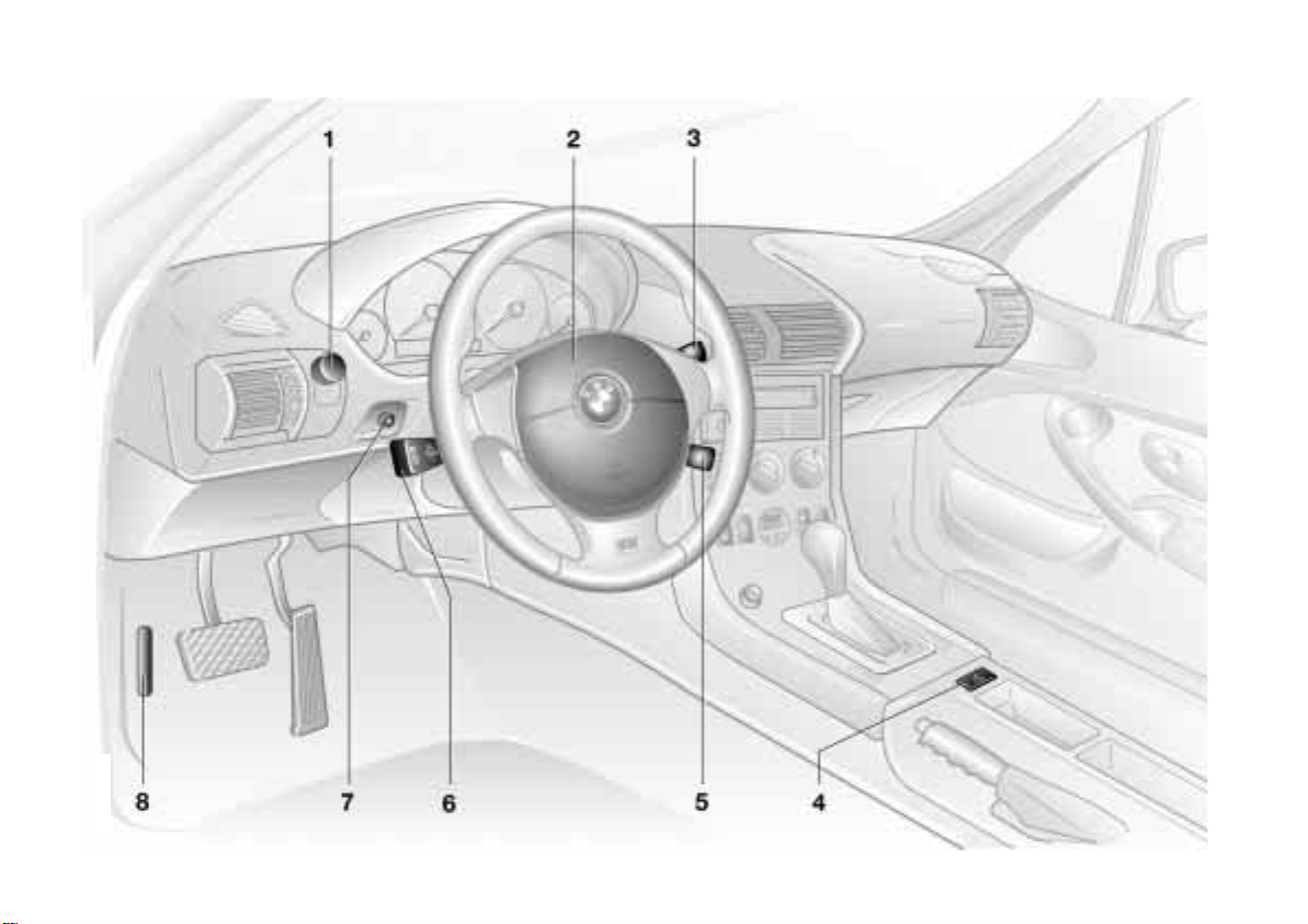
1 Parking lamps/Low beams 75
2 Horn
3 Wiper/Washer system 64
4 Hazard warning flashers 24
*
5 Cruise control
>
Turn signals 63
6
>
High beams 63
>
Headlamp flasher 63
>
Computer*69
7 Fog lamps 75
8 Hood release 116
66
17n
Index Data Technology Repairs Car care Controls Overview
Page 18
18n
Online Edition for Part No. 01 41 0 155 690 - © 09/00 BMW AG
Instrument cluster
367us705
Page 19

Instrument cluster
Online Edition for Part No. 01 41 0 155 690 - © 09/00 BMW AG
19n
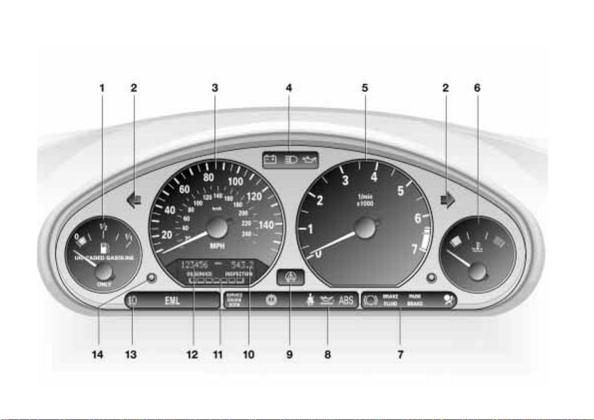
1 Fuel gauge with indicator lamp
for reserve range 67
2 Indicator lamp for turn signals 23
3 Speedometer
4 Indicator and warning lamps for:
>
Battery charge current 20
>
High beams 23
>
Engine oil pressure 20
5 Tachometer 67
6 Coolant temperature gauge 68
7 Indicator and warning lamps for:
>
Brake pad wear 22
>
Brake hydraulic
system 20, 21, 22
>
Parking brake 21
>
Airbags 21
8 Indicator and warning lamps for:
>
Service Engine Soon 22
>
Automatic transmission*22
>
Safety belts 21
>
Engine oil level 21
>
Antilock Brake System (ABS) 21
9 Indicator lamp for Automatic
Stability Control plus Traction
(ASC+T)/Dynamic Stability Control
*
(DSC
10 Trip odometer/Gear indicator for
automatic transmission with
Steptronic
and ADB*/DBC) 22
*
67
11 Service Interval Display 68, 126
12 Odometer 67
13 Indicator and warning lamps for:
>
Front fog lamps*23
>
Engine electronics 22
14 Trip odometer reset button 67
The illustration shows the instrument
cluster in the US version. In the Canadian models, some of the indicator and
warning lamps have a different appearance. Refer to pages 20 to 23.
Index Data Technology Repairs Car care Controls Overview
Page 20
20n
Online Edition for Part No. 01 41 0 155 690 - © 09/00 BMW AG
Indicator and warning lamps
Technology that monitors itself
Many of the systems of your BMW
monitor themselves automatically, both
during engine starts and while you are
driving. Indicator and warning lamps
●
that are identified by "
proper functioning whenever the ignition key is turned. They each light up
once for different periods of time.
If a fault should occur in one of these
systems, the corresponding lamp does
not go out after the engine is started or
it lights up while the vehicle is moving.
You will see how to react to this below.
" are tested for
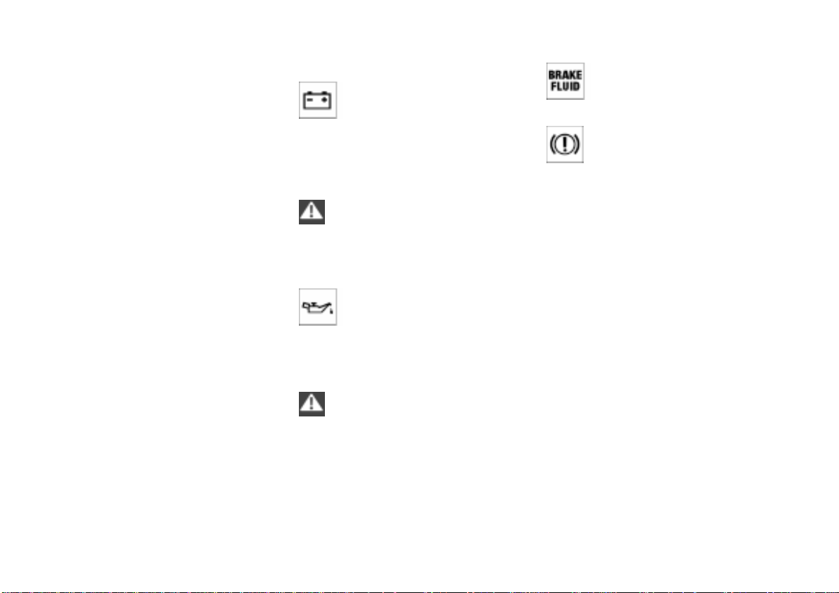
Red: stop immediately
Battery charge current
The battery is no longer being
charged. The alternator drive
belt is defective or there is a malfunction in the charging circuit of the alternator. Please contact the nearest BMW
center.
If the drive belt is defective, do not
continue driving. The engine could
be damaged due to overheating.
Increased force is required to steer the
vehicle if the drive belt is defective.
Engine oil pressure
Stop the vehicle and switch off
the engine immediately. Check
the engine oil level. Top up as required.
If oil level is correct: please contact the
nearest BMW center.
Do not continue driving. The
engine could be damaged
because of inadequate lubrication.
●
<
●
<
Brake hydraulic system
The brake fluid level is too low.
Before driving further, be sure to
read the notes on pages 102 and 124.
Brake hydraulic system warning
lamp for Canadian models.
●
Page 21
Indicator and warning lamps
Online Edition for Part No. 01 41 0 155 690 - © 09/00 BMW AG
21n
Red and yellow: continue to drive
cautiously
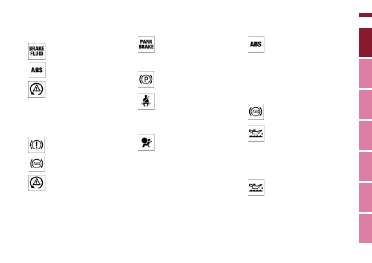
If the red warning lamp for the
brake hydraulic system comes
on together with the yellow indicator lamps for ABS, ASC+T/
*
and ADB*/DBC: the
DSC
entire ABS, CBC, ASC+T/DSC
and ADB*/DBC control system
has failed. Continue to drive
cautiously and defensively and
avoid full brake applications. Have the
system checked by your BMW center
as soon as possible.
For additional information, refer to
pages 72, 73 and 100.
Warning lamps for Canadian
models.
Red: an important reminder
Parking brake
Comes on when the parking
brake is applied.
For additional information, refer to
page 57.
*
are fastened.
For additional information on safety
belts, refer to page 49.
For additional information, refer to
pages 51 and 166.
Parking brake warning lamp for
Canadian models.
Please fasten your safety belt
Together with an acoustic signal.
Comes on until the safety belts
Airbags
Please have the system
inspected by your BMW center.
●
Yellow: check as soon as possible
Antilock Brake System (ABS)
Comes on during normal vehicle
operation: ABS has been deactivated in response to system malfunction. Conventional braking efficiency
is available without limitations. Please
have the system inspected by your
BMW center.
For additional information, refer to
●
page 99.
Antilock Brake System warning
lamp for Canadian models.
Engine oil level
Comes on while driving: the
oil level is at the absolute
minimum; refill as soon as possible. Do
not drive more than approx. 30 miles
(50 km) until you add oil.
For additional information, refer to
page 121.
Engine oil level
Comes on after the engine has
been shut off: add engine oil at
your earliest opportunity (when you
stop to refuel).
For additional information, refer to
page 121.
●
Index Data Technology Repairs Car care Controls Overview
Page 22
22n
Online Edition for Part No. 01 41 0 155 690 - © 09/00 BMW AG
Indicator and warning lamps
Automatic transmission
Because of a malfunction, the
automatic transmission shifts
only in the emergency program. Please
consult the nearest BMW center.
For additional information, refer to
pages 60, 63.
Brake pads
Have the brake pads checked.
For additional information, refer
to page 102.
Automatic Stability Control plus
Traction (ASC+T)/Dynamic
Stability Control (DSC)
*
/DBC
ADB
Indicator lamp flashes:
The system is active and governs drive
force and braking force.
The indicator lamp stays lit:
ASC+T has been turned off via the
switch or it is defective, or the DSC
has been turned off, the ADB
operational.
Please consult the nearest BMW
center.
For additional information, refer to
pages 72, 73.
●
●
*
*
and
* is
*
Dynamic Stability Control
* and ADB*/DBC ●
(DSC)
The indicator lamps remain on:
The DSC
been turned off via the switch or
they are defective.
Please consult the nearest BMW
center.
For additional information, refer to
page 73.
Indicator and warning lamps for
Canadian models.
* and ADB*/DBC have
Service Engine Soon ●
If the indicator lamp comes on
either continuously or intermittently, this indicates a fault in the emissions-related electronic systems.
Although the vehicle remains operational, you should have the systems
checked by your BMW center at the
earliest possible opportunity.
For additional information, refer to
page 137.
Service Engine Soon warning
lamp for Canadian models.
Engine electronics ●
There is a fault in the engine's
electronic control system. You
can continue to drive with reduced
engine output or engine speed. Please
have the system inspected by your
BMW center.
Page 23

Indicator and warning lamps
Online Edition for Part No. 01 41 0 155 690 - © 09/00 BMW AG
23n
Green: for your information
Turn signals
Flashes when the turn signals
are in operation. Rapid flashing
indicates a system malfunction.
For additional information, refer to
page 63.
Front fog lamps
Lights up whenever you switch
on the front fog lamps.
For additional information, refer to
page 75.
*
Blue: for your information
High beams
Lights up when the high beams
are on or the headlamp flasher
is actuated.
For additional information, refer to
page 63.
Index Data Technology Repairs Car care Controls Overview
Page 24
24n
Online Edition for Part No. 01 41 0 155 690 - © 09/00 BMW AG
Hazard warning flashers Warning triangle* First-aid kit*
Z3 coupe
In the luggage compartment at the left
rear. Release the Velcro
Z3 roadster
In the luggage compartment on the
right in a storage tray.
Some of the articles in the first-aid
367de025
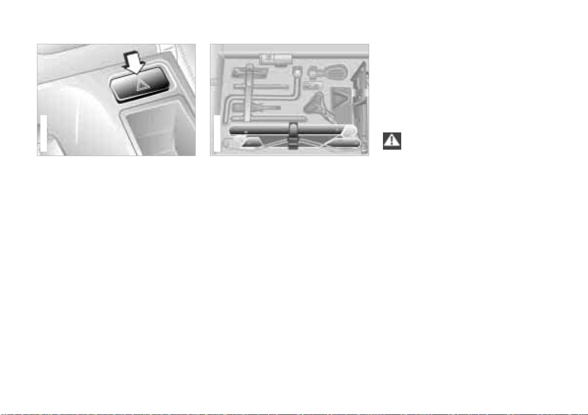
The push-button flashes rhythmically
when the hazard flashers are on.
To help you locate the switch in an
emergency, the button is also illuminated whenever the vehicle lamps
are on.
367de684
Z3 coupe
Z3 coupe
The warning triangle is located in the
luggage compartment under the floor
mat so that it is readily accessible (refer
to the illustration).
Grasp the floor mat by the straps on the
left and right. Pull it upward and remove
it.
kit may be used within a limited
time only. For this reason, check the
expiration dates of each of the items
regularly, and replace any whose expiration dates have passed. You can
acquire replacements in any drugstore
or pharmacy. Comply with legal
requirements which cover availability of
a first-aid kit in the vehicle.<
Z3 roadster
The warning triangle is located in the
luggage compartment in the area of the
sill.
® fasteners.
Page 25
Refueling
Online Edition for Part No. 01 41 0 155 690 - © 09/00 BMW AG
25n
367de391
Before filling the tank, shut off the
engine, as otherwise fuel cannot
flow into the tank and the Service
Engine Soon warning lamp may come
on. Refer to page 22.<
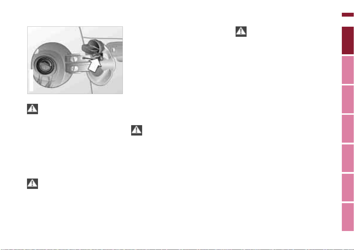
Open the fuel filler cap:
Open the fuel filler door, turn the fuel
filler cap counterclockwise and remove
the cap. Place the filler cap in the
bracket attached to the fuel filler door.
Open the filler cap carefully. If you
do not, fuel could spray out.<
When refueling, insert the filler nozzle
completely into the filler pipe. Pulling
the nozzle out of the pipe during refueling
> results in premature shutoff
> and will reduce the effect of the vapor
recovery system.
If the filler nozzle is operated correctly,
the fuel tank is full when it shuts off the
first time.
Tank capacity: refer to page 173.
Close the fuel filler cap:
Position the cap on the neck. Turn the
cap clockwise to the stop.
Close the filler cap carefully after
refueling until a "click" is heard.
While closing, be sure not to squeeze
the strap which is fastened to the cap.
A loose or missing cap will activate the
Service Engine Soon lamp.<
Close the fuel filler door.
When handling fuels, comply with
all of the applicable safety
precautions and regulations pertaining
to fuels.
Never carry spare fuel containers in
your vehicle. Whether they are empty or
full, these containers can leak, cause an
explosion, or lead to fire in the event of
a collision.<
Index Data Technology Repairs Car care Controls Overview
Page 26
26n
Online Edition for Part No. 01 41 0 155 690 - © 09/00 BMW AG
Fuel specifications Tire inflation pressure
The engine uses lead-free gasoline
only.
Required fuel:
> Premium Unleaded Gasoline,
min. 91 AKI.
AKI = Anti Knock Index
Do not use leaded fuels. The use
of leaded fuels will cause permanent damage to the system's oxygen
sensor and the catalytic converter.<
367de388
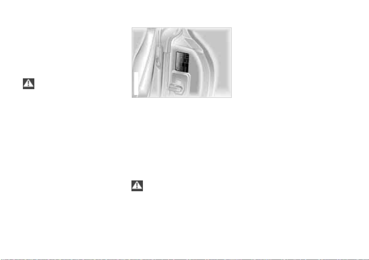
The inflation pressures are indicated on
a label attached to the B-pillar behind
the driver's door (visible with door
open).
Check tire pressures
All pressure specifications are indicated
in psi (kilopascal [kPa]) with the tires at
ambient temperature (refer also to the
next page).
Check tire inflation pressures
regularly – at least every two
weeks and before beginning a longer
trip. Incorrect tire pressure can otherwise lead to tire damage and accidents.
Check the air pressure of the spare tire
as well. Refer to the following table and
to page 108.<
Comply with tire approval
specifications
The inflation pressures in the table apply
to tires made by BMW-approved manufacturers. Your BMW center is familiar
with these pressures. Higher pressures
may be specified for tires made by other
manufacturers. You will find a list of
approved tires beginning on page 114.
Your vehicle is equipped with tires that
meet both US standards and European
standards. We recommend the exclusive use of BMW-approved tires.
Page 27
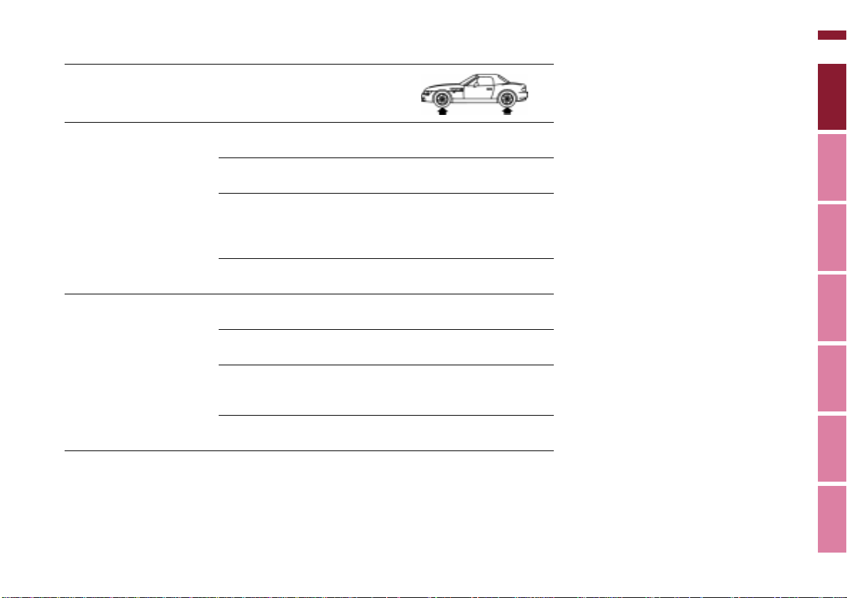
Tire inflation pressure
Online Edition for Part No. 01 41 0 155 690 - © 09/00 BMW AG
BMW Tires
All tire pressures are in psi
(kilopascals [kPa])
27n
Z3 roadster 2.5i
Z3 roadster 3.0i
Z3 coupe 3.0i
225/50 R 16 92 V
225/50 ZR 16
Front: 225/45 ZR 17
Rear: 245/40 ZR 17
205/60 R 15 91 Q M+S
205/55 R 16 91 Q M+S
225/50 R 16 92 Q M+S
225/45 R 17 91 Q M+S
Spare tire:
T 115/90 R 16 92 M
225/50 R 16 92 V
225/50 ZR 16
Front: 225/45 ZR 17
Rear: 245/40 ZR 17
205/55 R 16 91 Q M+S
225/50 R 16 92 Q M+S
225/45 R 17 91 Q M+S
Spare tire:
T 115/90 R 16 92 M
29 (200) 32 (220)
29 (200)
–
32 (220) 35 (240)
61 (420) 61 (420)
29 (200) 32 (220)
29 (200)
–
32 (220) 35 (240)
61 (420) 61 (420)
–
32 (220)
–
32 (220)
Index Data Technology Repairs Car care Controls Overview
Page 28
28n
Online Edition for Part No. 01 41 0 155 690 - © 09/00 BMW AG
Opening and closing:
Keys 30
Electronic vehicle
immobilizer 31
Central locking system 32
Opening and closing from the
outside 32
Opening and closing from the
inside 33
Luggage compartment lid 34
Electric power windows 35
Sunroof, coupe 36
Convertible top 37
Adjustments:
Seats 46
Mirrors 48
Safety systems:
Safety belts 49
Airbags 51
Transporting children safely 53
Driving:
Steering/Ignition lock 55
Starting the engine 56
Switching off the engine 57
Parking brake 57
Manual transmission 58
Automatic transmission 59
Automatic transmission with
Steptronic 61
Turn signals/High beams 63
Controls
Page 29

29n
Online Edition for Part No. 01 41 0 155 690 - © 09/00 BMW AG
Wiper/Washer system 64
Rear window defroster 65
Cruise control 66
Everything under control:
Odometer 67
Tachometer 67
Fuel gauge 67
Temperature gauge 68
Service Interval Display 68
Clock 69
Computer 69
Technology for safety
and convenience:
Automatic Stability Control
plus Traction (ASC+T) 72
Dynamic Stability Control
(DSC) 73
Lamps:
Parking lamps/Low beams 75
Fog lamps 75
Interior lamps 76
Reading lamps 77
Controlling the climate
for pleasant driving:
Heating and ventilation 78
Heating and ventilation/
Air conditioner 82
Seat heating 87
Cabin convenience:
Glove compartment 88
Additional storage areas 88
Storage boxes 88
Beverage holder 89
Ashtray 89
Cigarette lighter 90
Loading and transporting
cargo:
coupe:
Roll-up cover 91
Partition net 91
Cargo loading 92
Roof-mounted luggage
rack 93
Overview
Controls and features
Operation, care
and maintenance
Owner service procedures
Advanced technology
Technical data
Index
Index Data Technology Repairs Car care Controls Overview
Page 30
30n
Online Edition for Part No. 01 41 0 155 690 - © 09/00 BMW AG
Keys
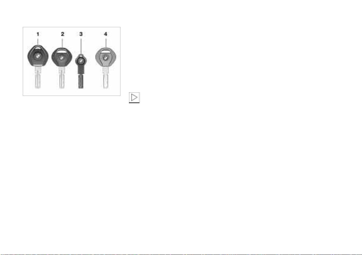
365de122
1 Master key with battery-powered
lamp (switch on by pressing the BMW
symbol)
2 Master key without lamp
3 Spare key for storage in a safe place
such as your wallet. This key is not
intended for continuous use
4 Door and ignition key
The luggage compartment lid and the
storage boxes
with this key – this is useful for valet
parking, for instance
* cannot be opened
Replacement keys
Replacement keys are available exclusively through your BMW center. Your
BMW center is obligated to ensure that
a person requesting a key is authorized
to do so since the keys belong to a
security system (refer to "Electronic
vehicle immobilizer" on the following
page).
Whenever you receive a new
replacement key, turn that key to
position 2 in the ignition lock once (ignition switched on) and then back. This
allows the electronic vehicle immobilizer to "learn" the new key.<
Page 31

Electronic vehicle immobilizer
Online Edition for Part No. 01 41 0 155 690 - © 09/00 BMW AG
31n
The key to security
The electronic vehicle immobilization
unit increases the anti-theft protection
of your BMW – you do not have to
adjust or activate anything. This electronic immobilization system is
designed to reduce the susceptibility of
the vehicle to theft by making it impossible to start the engine using any
means other than the special keys
furnished with the vehicle.
Your BMW center can cancel the electronic system authorization for individual keys (in the event a key is lost,
for instance). A deactivated key can no
longer be used to start the engine.
How the electronics work
At the heart of this system is an electronic chip which is integrated into the
key. The lock mechanism itself is actually a dual-function device, simultaneously serving as a communications
interface designed to allow the security
system to maintain a continuous stream
of variable, vehicle-specific signals with
the electronic circuitry in the key. The
system will not release the ignition, fuel
injection and starter unless it recognizes an "authorized" key.
Force applied to the key can
damage the integrated electronic
circuitry. A damaged key can no longer
be used to start the engine.<
For US owners only
The transmitter and receiver units
comply with part 15 of the FCC (Federal
Communications Commission) regulations. Operation is governed by the
following:
FCC ID: LX8EWS
Compliance statement:
This device complies with part 15 of the
FCC Rules. Operation is subject to the
following two conditions:
> This device may not cause harmful
interference, and
> this device must accept any interfer-
ence received, including interference
that may cause undesired operation.
Any unauthorized modifications
to these devices could void the
user's authority to operate the equipment.<
Index Data Technology Repairs Car care Controls Overview
Page 32
32n
Online Edition for Part No. 01 41 0 155 690 - © 09/00 BMW AG
Central locking system Opening and closing from the outside
The concept
The central locking system becomes
operational when the doors are closed.
The system simultaneously engages
and releases the locks on the
> doors
> luggage compartment
> fuel filler door.
The central locking system can be
operated
> from outside via the door locks and
the luggage compartment lock
> from inside via the safety lock
buttons (locks doors only).
The alarm system is automatically
armed whenever you activate the
central locking system from outside the
vehicle. It prevents the doors from
being unlocked with the lock buttons or
release handles.
The central locking system unlocks
automatically in the event of an accident. In addition, the hazard warning
flashers and interior lamps come on.
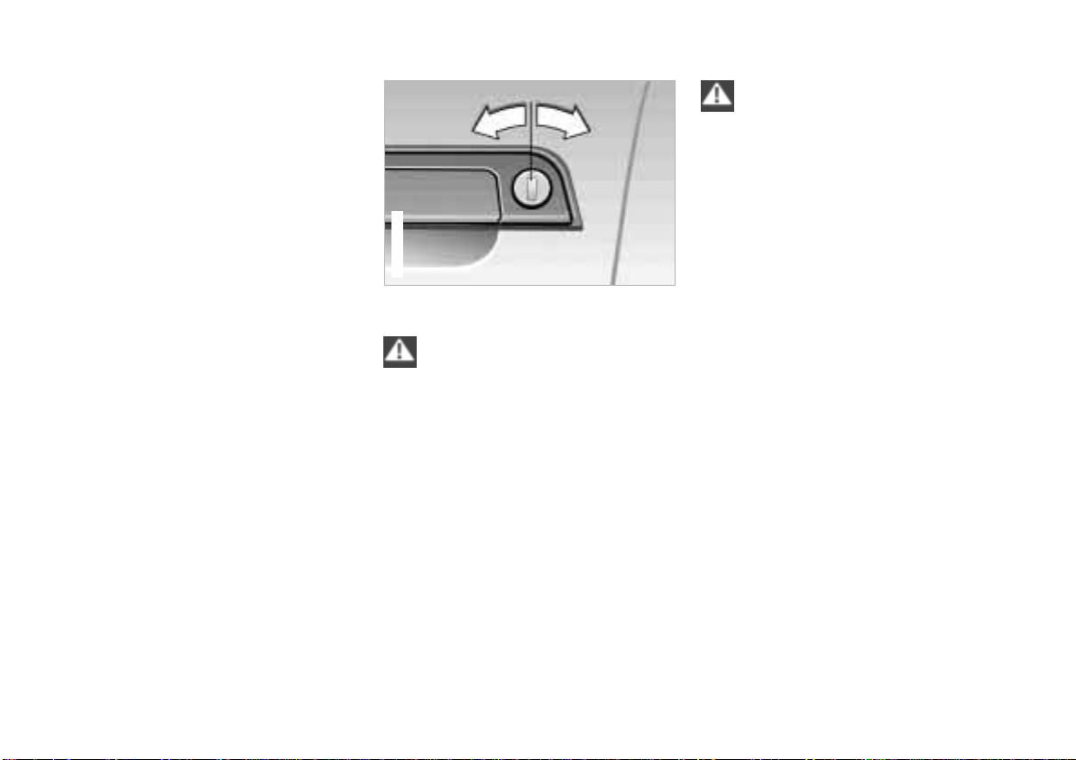
367de011
With the key
If the vehicle has been locked
from the outside, persons
remaining inside the vehicle cannot
unlock it.<
Convenience locking mode
Electrically powered windows can also
be closed via the door locks:
When the doors are closed, hold the
key in the "Lock" position.
Watch the closing process care-
fully and be sure that no one is
trapped by the closing motion. The
movement stops when you release the
key.<
Manual operation
(in the event of electrical failure)
Turn the key all the way to the extreme
left or right to unlock/lock the door.
Page 33

Opening and closing from the inside
Online Edition for Part No. 01 41 0 155 690 - © 09/00 BMW AG
33n
To unlock and open the doors
> Pull the door handle of a door twice:
the initial pull unlocks the door, and
the second opens it.
To engage the locks
When the lock button of any door is
pressed down, the doors and luggage
compartment are locked. The anti-theft
system is not activated.
The fuel filler door also remains
unlocked to allow refueling.
To avoid being accidentally locked out
of the vehicle:
> The vehicle cannot be locked with
the lock button when the driver's
door is open.
> The lock button on the passenger's
door only operates the central
locking system if both doors are
closed.
Children might be able to lock the
doors from the inside. For this
reason, always take the vehicle's keys
with you so that the vehicle can be
opened again from the outside at any
time.<
Index Data Technology Repairs Car care Controls Overview
Page 34
34n
367de625
Z3 coupe
Online Edition for Part No. 01 41 0 155 690 - © 09/00 BMW AG
Luggage compartment lid
367de368
Z3 roadster
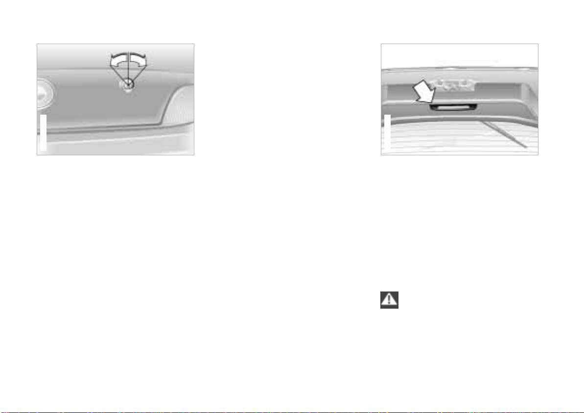
The lock
The illustration depicts the luggage
compartment lock of the Z3 roadster
as an example.
The controls and function for the
Z3 coupe are the same as for
the Z3 roadster.
Only the master keys (refer to page 30)
will fit in the luggage compartment lock.
Locking separately
Turn the master key to the right past the
resistance point and then pull it out in
the horizontal position
This locks the luggage compartment
and disengages it from the central
locking system. If you then surrender
only the door and ignition key (refer to
page 30), access to the vehicle through
the luggage compartment is not
possible. This is recommended for valet
parking, for instance.
Manual operation
(in the event of electrical failure)
Turn the master key in the lock of the
luggage compartment lid to the left to
the stop – the luggage compartment
opens slightly.
The luggage compartment is locked
again as soon as it is closed.
To close
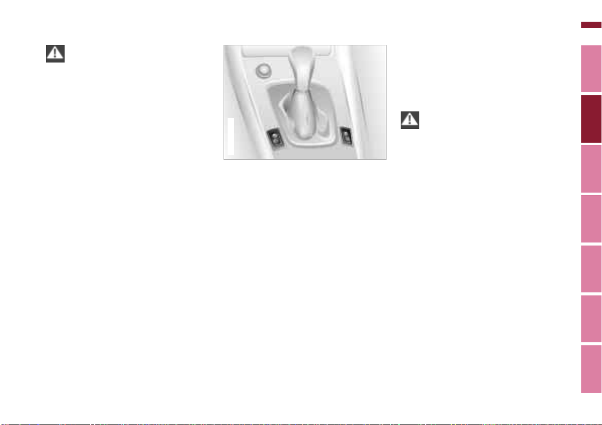
The illustration depicts the luggage
compartment lid of the Z3 coupe.
The handle recess in the interior trim
panel of the luggage compartment lid
(arrow) makes it easier to pull the lid
down.
On the Z3 roadster, the handle recess
is located to the left of the lock mechanism.
To avoid injuries, be sure that the
travel path of the luggage
compartment lid is clear when it is
closed, as with all closing procedures.<
Page 35
Luggage compartment lid Electric power windows
Online Edition for Part No. 01 41 0 155 690 - © 09/00 BMW AG
35n
Do not drive with the luggage
compartment lid open, since
exhaust fumes could penetrate the interior of the vehicle. Should it be absolutely necessary to operate the vehicle
with the luggage compartment lid open
(coupe; roadster with closed convertible top):
> Close all windows. On the coupe,
close the sunroof.
> Increase the air supply of the heating
and ventilation system to a high level.
Refer to page 78 or 82.<
367de668
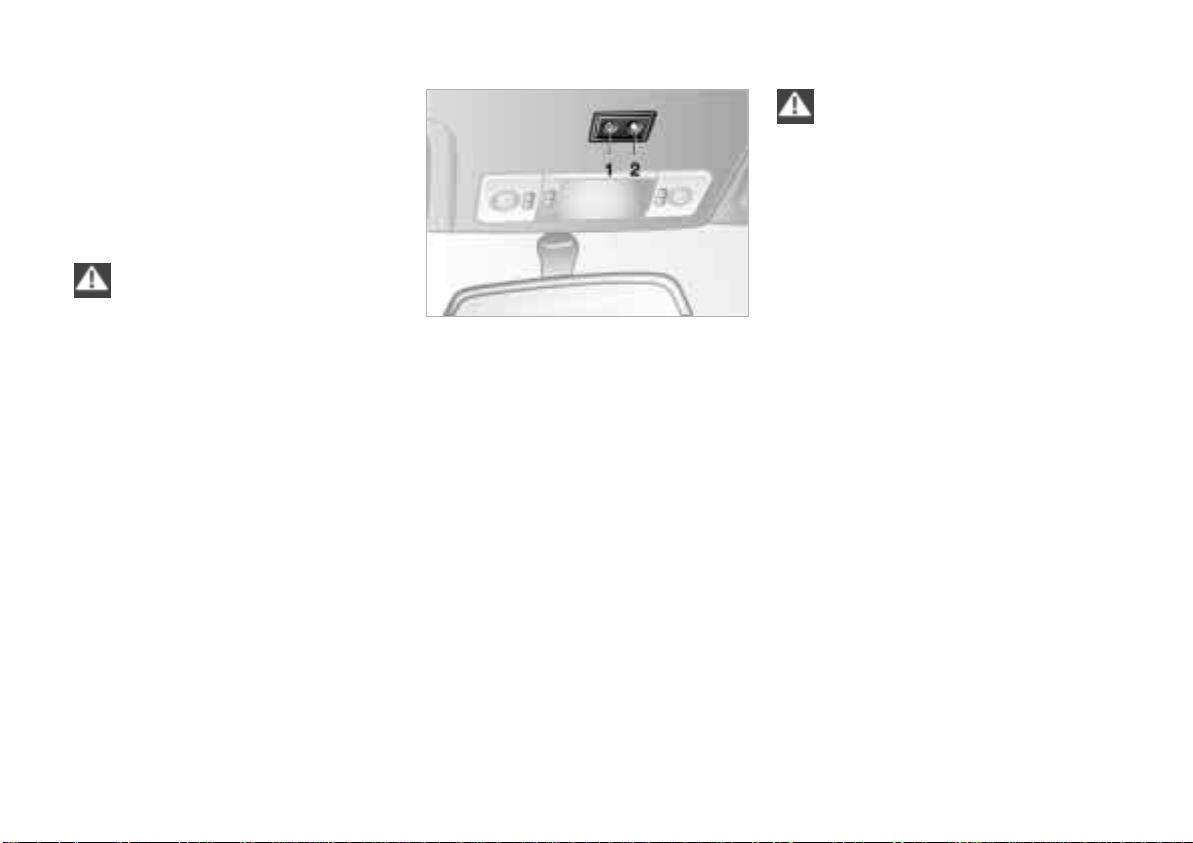
Opening and closing windows
From ignition key position 1 and up:
> Depress the rocker switch until you
feel resistance:
The window continues moving for as
long as you maintain pressure on the
switch.
> Press the rocker switch beyond the
pressure point (one-touch mode):
The window moves automatically.
Press the switch a second time to
stop the window.
After the ignition has been switched off:
Actuation is still possible for up to
15 minutes in ignition key position 0 or
if the ignition key has been removed, as
long as no doors have been opened.
Because the power windows are
sealed at high pressure to prevent
wind noise when closed, a powerful
motor is required for efficient closing.
When closing the windows, always
ensure that they are not obstructed in
any way. Unsupervised use of these
systems can result in serious personal
injury. Remove the ignition key to deactivate the electric power windows
whenever you leave the vehicle. Never
leave the keys in the vehicle with unsupervised children.
Never place anything that could
obstruct the driver's vision on or next to
the windows.<
For convenience closing via the door
lock, refer to page 32.
Index Data Technology Repairs Car care Controls Overview
Page 36
36n
Online Edition for Part No. 01 41 0 155 690 - © 09/00 BMW AG
Electric power windows Sunroof*, coupe
Jam protection
If one of the windows comes into
contact with an object between the
window and roof frame when it is
closing, the closing cycle is interrupted
immediately and the window will open
again slightly.
You can override this jam protec-
tion function (if there is an
attempted unauthorized entrance from
the outside, for instance) by pressing
the switch beyond the resistance point
and holding it.<
367de689
Z3 coupe
Lifting – Closing
From ignition key position 1 and up:
To lift: press button 1.
To close: press button 2.
To prevent injuries, exercise care
when closing the sunroof. Keep it
in your field of vision until it is closed.<
To avoid pressure or drafts in the
passenger compartment when the
sunroof is open, keep the air vents in
the dashboard open and increase the
air supply if necessary. Refer to
pages 78 and 82.
Page 37
Manual convertible top, roadster
367de399
Online Edition for Part No. 01 41 0 155 690 - © 09/00 BMW AG
Weather protection
The convertible top combines reliable
protection from the elements with
simple, convenient operation. Here are
a few tips to ensure that you have pleasure with your roadster.
It is advisable to close the convertible
top when the vehicle is parked. The
closed convertible top not only protects
the passenger compartment from
unforeseeable damage from the
weather, it also provides a certain
degree of theft protection. In addition,
keep valuables only in the locked
luggage compartment, even with the
convertible top closed.
Never mount a roof-mounted luggage
rack on the convertible top. Please
contact your BMW center for suitable
securing devices and additional accessories.
To prevent damage, do not operate the
convertible top at temperatures at the
freezing point.
367de046
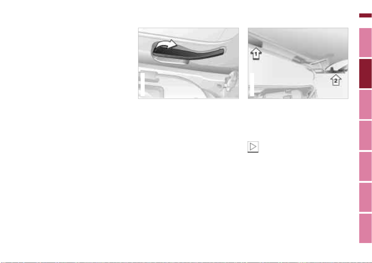
To open
1 With the doors closed, lower the side
windows a few inches (centimeters).
2 To release the convertible top: pull
the levers outward on the left and the
right of the convertible top frame
(refer to the illustration).
37n
3 Raise the convertible top approx.
8 inches (20 cm) from the convertible
top frame on the inside to relieve
tension on the top. Refer to arrow 1.
Be sure that the convertible top
folds at the front linkage joints first
(refer to arrow 2). If it does not, the
convertible top linkage could be bent.<
4 Continue to raise the top at the front
and push it toward the rear into the
convertible top well.
In the process, make sure the rear
window is laid down evenly and free
of creases. To prevent the rear
window from being scratched, a soft
cloth should be laid in the window
fold.
Index Data Technology Repairs Car care Controls Overview
Page 38
38n
367us669
Online Edition for Part No. 01 41 0 155 690 - © 09/00 BMW AG
Manual convertible top, roadster
5 Fold the release lever against the
convertible top frame.
In order to avoid subsequent
moisture damage, do not open
and store the convertible top when it is
wet (refer also to the chapter on vehicle
care).<
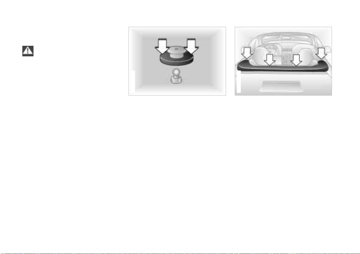
367de274
To mount the cover
The illustration depicts a representative
schematic of the fasteners for the
convertible cover.
To secure, press the outer ring of the
cover fastener onto the mating piece on
the vehicle (refer to the arrows).
The attachment points of the cover are
indicated by the four arrows in the illustration.
1 Position the convertible cover on the
convertible top well and align the
upper portions of the fasteners with
the lower portions on the vehicle.
2 Lift the cover at the rear, reach
underneath it and engage the two
middle fasteners.
3 Attach the front fasteners.
Page 39
Manual convertible top, roadster
367us670
Online Edition for Part No. 01 41 0 155 690 - © 09/00 BMW AG
39n
367us077
4 Push the peripheral frame of the
cover under the edge of the convertible top well.
5 Check the convertible cover to be
sure it is properly secured.
In order to avoid damage and
soiling of the inside of the convertible top, always drive with the cover
secured in place.<
Be sure that the cover is secured
properly on the vehicle. If it is not
firmly secured, the flow of air while
driving could loosen the cover at higher
speeds.<
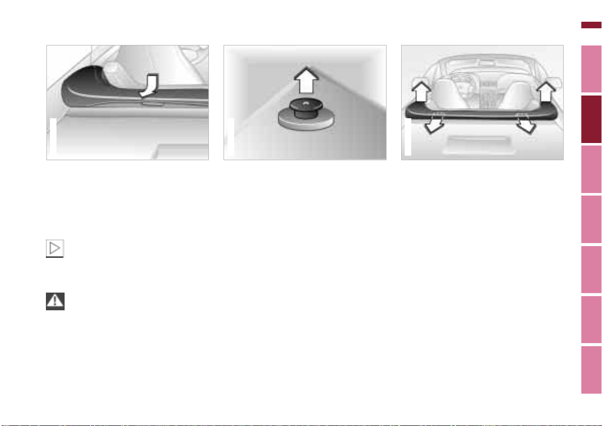
367de724
To close
1 To remove the convertible top cover:
> Loosen the fasteners. Pull the cap
of the latch upward. Refer to the
arrow.
> Loosen the front fasteners (outer
arrows).
> Pull the outer frame of the cover
under the edge of the convertible
top well.
> Lift the cover from the rear and
release the middle fasteners
(middle arrows).
Index Data Technology Repairs Car care Controls Overview
Page 40
40n
Online Edition for Part No. 01 41 0 155 690 - © 09/00 BMW AG
Manual convertible top, roadster
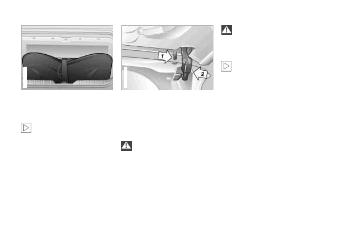
367de247
> To avoid damage, carefully fold the
cover and store it in the luggage
compartment.
Do not position heavy objects on
the cover.
If you store the cover away from the
vehicle, the cover should be spread
out.<
2 When the doors are closed, lower the
side windows slightly.
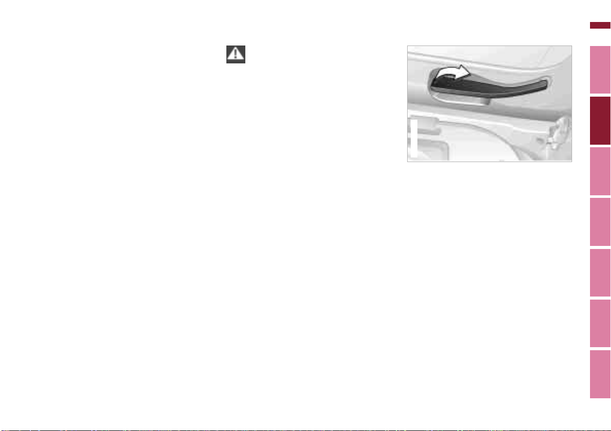
367de047
3 Pull the release lever away from the
frame as far as possible.
4 Holding the convertible top at the
front convertible top frame, lift it out
of the convertible top well and fold it
forward.
When folding the convertible top
forward, do not grasp it by the
side linkage. If you do so, there is a risk
of injury to your hands and fingers.<
5 Insert the pins 1, on the left and the
right, into the guides in the windshield frame. Using the handle recess
in the center of the convertible top
frame, pull the convertible top down.
Hold the top in this position and
secure both fasteners (refer also to
page 107).
Be sure that the fastener hooks 2
on the left and right are securely
engaged in the frame of the windshield.
If they are not, the convertible top could
open while the vehicle is moving.<
At higher speeds, it may occur
that the lower air pressure which
is created in the passenger compartment will cause the top or the rear
window to flutter. Increase the air
supply via the ventilation controls so
that a low pressure draft does not occur
in the vehicle.<
Page 41
Power convertible top, roadster*
367de046
Online Edition for Part No. 01 41 0 155 690 - © 09/00 BMW AG
41n
Weather protection
The convertible top combines reliable
protection from the elements with
simple, convenient operation. Here are
a few tips to ensure that you have pleasure with your roadster.
It is advisable to close the convertible
top when the vehicle is parked. The
closed convertible top not only protects
the passenger compartment from
unforeseeable damage from the
weather, it also provides a certain
degree of theft protection. In addition,
keep valuables only in the locked
luggage compartment, even with the
convertible top closed.
Never mount a roof-mounted luggage
rack on the convertible top. Please
contact your BMW center for suitable
securing devices and additional accessories.
To prevent damage, do not operate the
convertible top at temperatures at the
freezing point.
To conserve the battery, it is advisable
to operate the top only with the engine
running.
Operate the convertible top only
when the vehicle is stationary.
Do not lay objects on the convertible
top, since they would fall off when the
convertible top is operated and cause
damage or injuries.
Do not reach into the convertible top
mechanism during opening and closing.
Keep children away from the moving
parts of the convertible top during
operation.
The automatic sequence is interrupted
immediately if the button for actuating
the top (page 42 and 45) is released.
The sequence can be continued in the
desired direction by pressing the
button.<
To open
1 With the doors closed, lower the side
windows a few inches (centimeters).
2 To release the convertible top: pull
the levers outward on the left and the
right of the frame of the top (refer to
the illustration).
Index Data Technology Repairs Car care Controls Overview
Page 42
42n
Online Edition for Part No. 01 41 0 155 690 - © 09/00 BMW AG
Power convertible top, roadster*
367de399
367us366
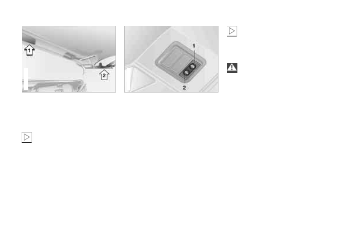
If the convertible top has not been
lifted far enough, or if the footbrake is not applied, the motor which
operates the convertible top will not
operate.<
In order to avoid subsequent
moisture damage, do not leave
the convertible top open when it is wet
(refer also to the chapter on vehicle
care).<
3 Raise the convertible top approx. 8 in
(20 cm) from the convertible top
frame on the inside to relieve tension
on the top. Refer to arrow 1.
Be sure that the convertible top
folds at the front linkage joints first
(refer to arrow 2). If it does not, the
convertible top linkage could be bent.<
4 Press the release lever against the
frame of the top.
5 Hold the footbrake down during the
entire opening procedure.
6 Lift the convertible top frame. Press
and hold the button for convertible
top operation in the "Open" direction (2) until the opening process is
completed and the cnvertible top is
folded into the convertible top well.
Page 43
Power convertible top, roadster*
367us077
Online Edition for Part No. 01 41 0 155 690 - © 09/00 BMW AG
43n
367de274
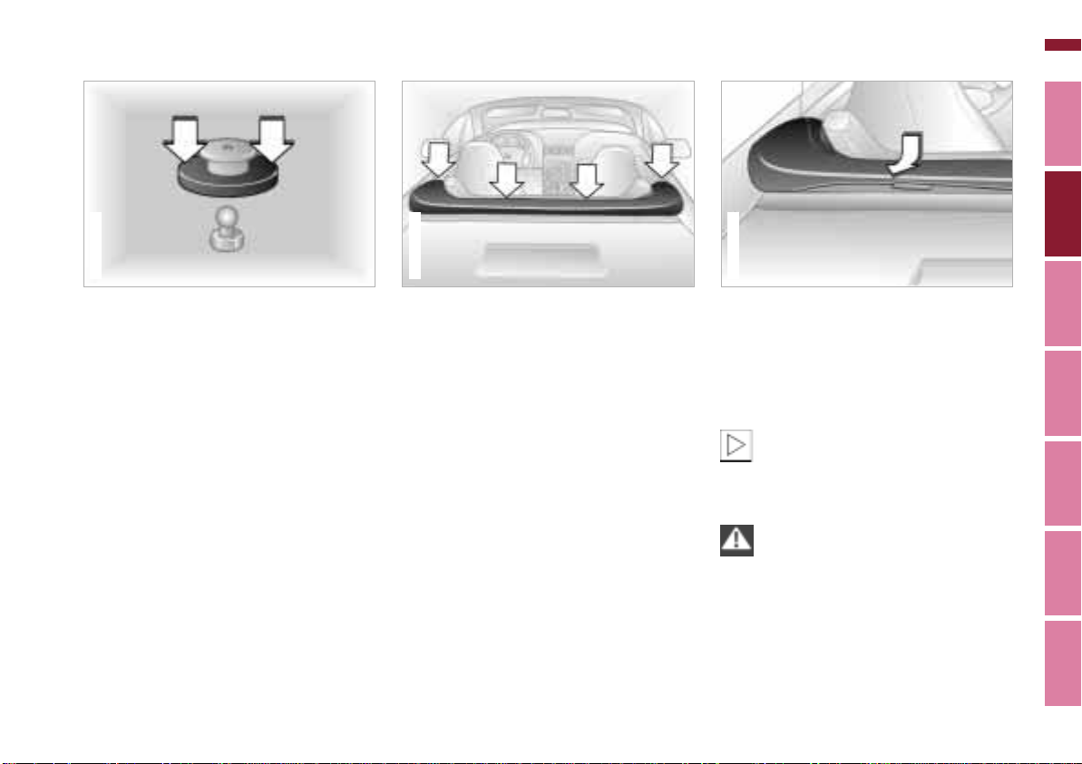
To mount the cover
The illustration depicts a representative
schematic of the fasteners for the
convertible cover.
To secure, press the outer ring of the
cover fastener onto the mating piece on
the vehicle (refer to the arrows).
367us669
The attachment points of the cover are
indicated by the four arrows in the illustration.
1 Position the convertible cover on the
convertible top well and align the
upper portions of the fasteners with
the lower portions on the vehicle.
2 Lift the cover at the rear, reach
underneath it and engage the two
middle attachments.
3 Attach the front fasteners.
4 Push the peripheral frame of the
cover under the edge of the convertible top well.
5 Check the convertible cover to be
sure it is properly secured.
In order to avoid damage and
soiling of the inside of the convertible top, always drive with the cover
secured in place.<
Be sure that the cover is secured
properly on the vehicle. If it is not
firmly secured, the flow of air while
driving could loosen the cover at higher
speeds.<
Index Data Technology Repairs Car care Controls Overview
Page 44
44n
367de247
Online Edition for Part No. 01 41 0 155 690 - © 09/00 BMW AG
Power convertible top, roadster*
367de724
To close
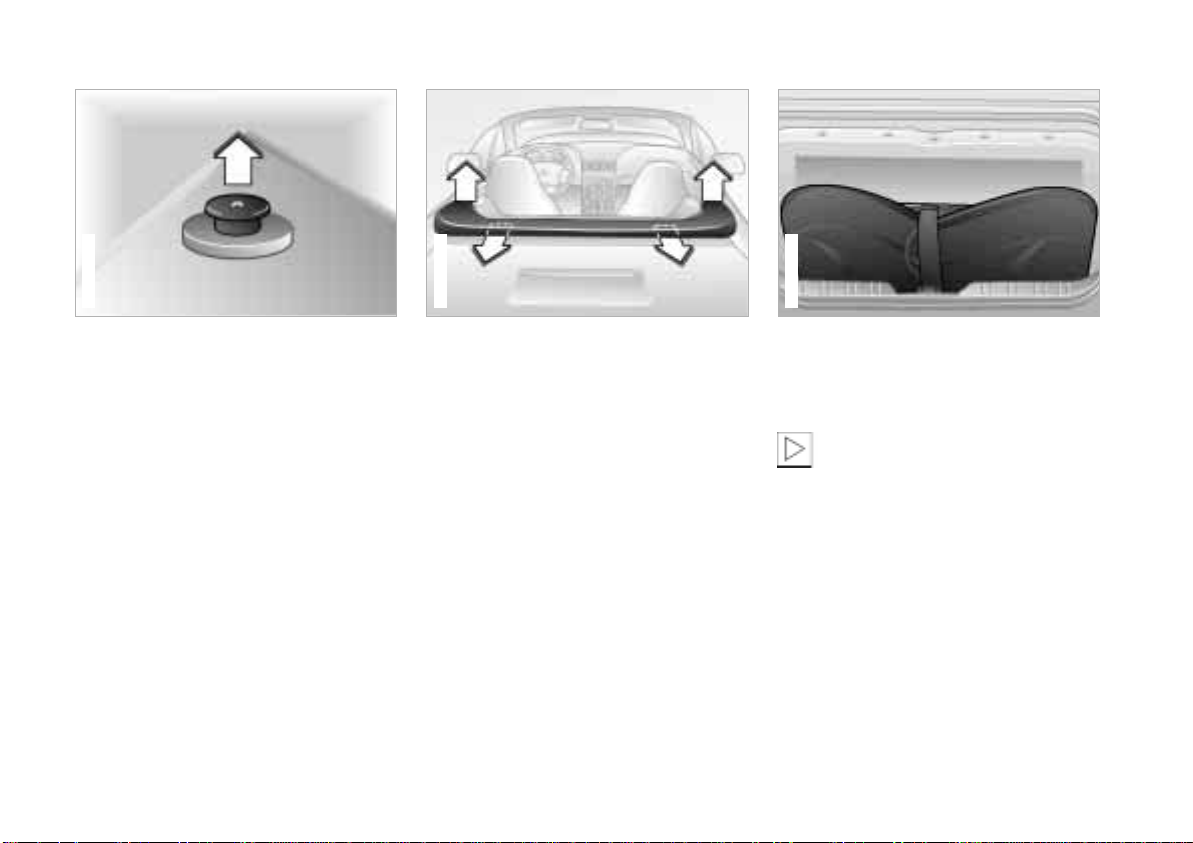
1 To remove the convertible top cover:
> Loosen the fasteners. Pull the cap
of the latch upward. Refer to the
arrow.
367us670
> Release the front fasteners (outer
arrows).
> Pull the outer frame of the cover
under the edge of the convertible
top well.
> Lift the cover from the rear and
release the middle fasteners
(middle arrows).
> To avoid damage, carefully fold the
cover and store it in the luggage
compartment.
Do not position heavy objects on
the cover.
The cover should be spread out if you
store it away from the vehicle.<
Page 45
Power convertible top, roadster*
Online Edition for Part No. 01 41 0 155 690 - © 09/00 BMW AG
45n
At higher speeds, it may occur
that the lower air pressure which
is created in the passenger compartment will cause the top or the rear
window to flutter. Increase the air
supply via the ventilation controls so
that a low pressure draft does not occur
in the vehicle.<
367us366
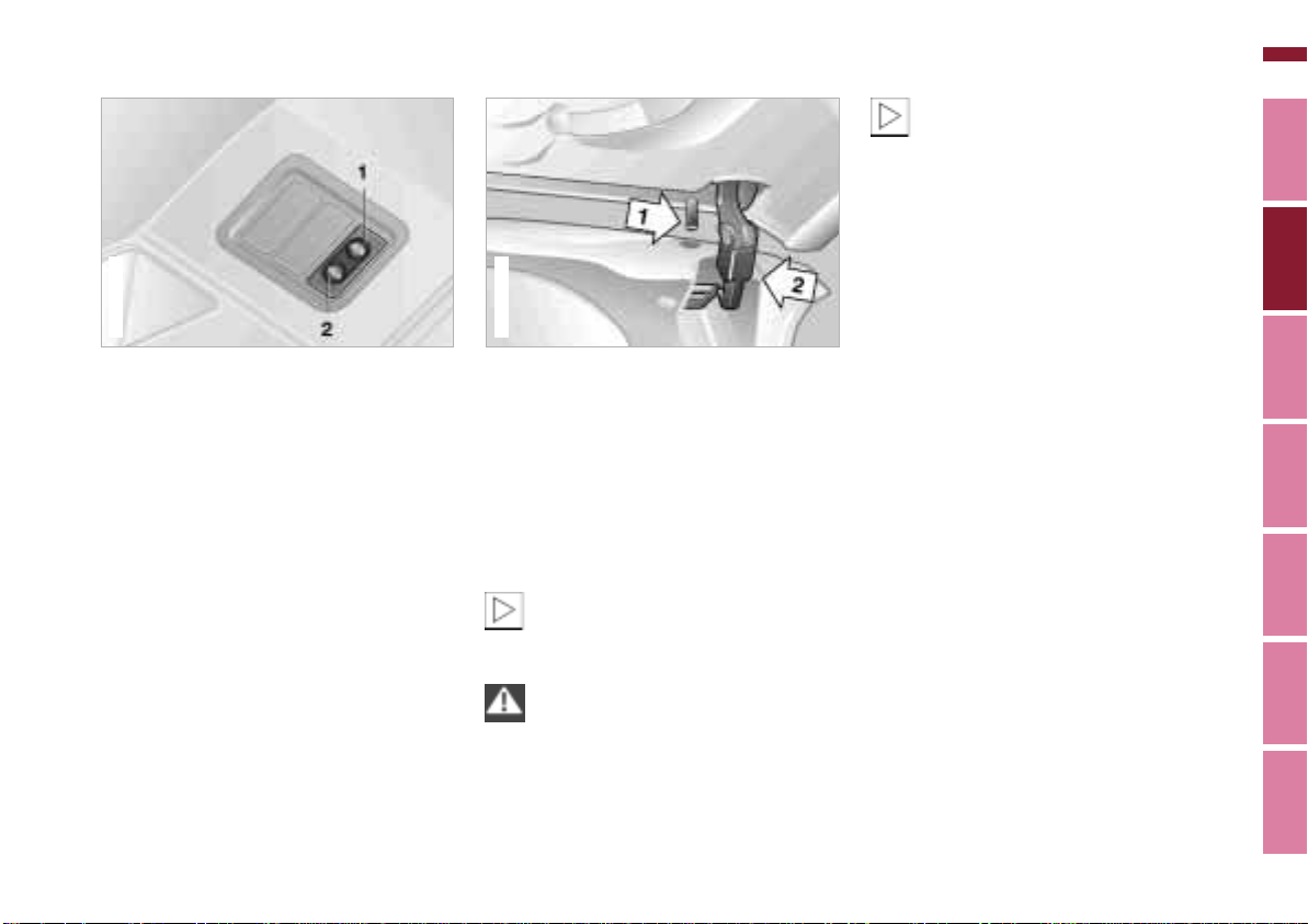
2 When the doors are closed, lower the
side windows slightly.
3 Pull the release lever away from the
frame as far as possible.
4 Hold the footbrake down during the
entire closing procedure.
5 Press and hold the button for
convertible top operation in the
"Close" direction (1) until the closing
process is completed and the
convertible top frame has docked
against the windshield frame.
367de047
6 Insert the pins 1, on the left and the
right, into the guides in the windshield frame. Using the handle recess
in the center of the convertible top
frame, pull the convertible top down.
Hold the top in this position and
secure both fasteners (refer also to
page 107).
If the footbrake is not applied, the
motor which operates the
convertible top will not operate.<
Be sure that the fastener hooks 2
on the left and right are securely
engaged in the frame of the windshield.
If they are not, the convertible top could
open while the vehicle is moving.<
Index Data Technology Repairs Car care Controls Overview
Page 46
46n
367de015
Online Edition for Part No. 01 41 0 155 690 - © 09/00 BMW AG
Seat adjustment
For maximum safety, please comply
with the following:
Never try to adjust your seat while
operating the vehicle. The seat
could respond with an unexpected
movement, and the ensuing loss of
vehicle control could result in an accident.
Be sure that the safety belt is fastened
firmly against your body at all times. In
the event of a frontal impact, a loose lap
belt could slide over your hips, leading
to abdominal injury. In addition, the
safety belt's restraint effectiveness is
reduced if the belt is worn loosely.
When adjusting your seat, select a
position that provides the maximum
distance between you and the steering
wheel, instrument panel and door while
still allowing comfortable and safe
access to all vehicle controls.<
Correct sitting posture
To reduce strain on your spinal column,
sit all the way back in the seat and rest
your back fully against the backrest.
In the ideal sitting posture, your head
extends along a straight line from your
spine.
For long-distance driving, you may wish
to increase the backrest tilt angle
slightly to reduce muscular tension.
You should also be able to grasp the
highest point of the steering wheel with
your arms slightly bent.
After a seat adjustment in the coupe,
adjust the height of the safety belt also.
Refer to page 49.
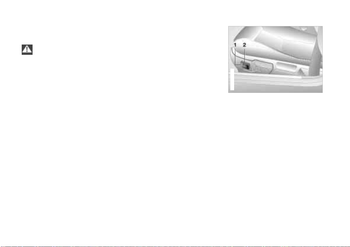
1 Height
2 Backward/Forward adjustment
*
Page 47
Seat adjustment
Online Edition for Part No. 01 41 0 155 690 - © 09/00 BMW AG
367de076
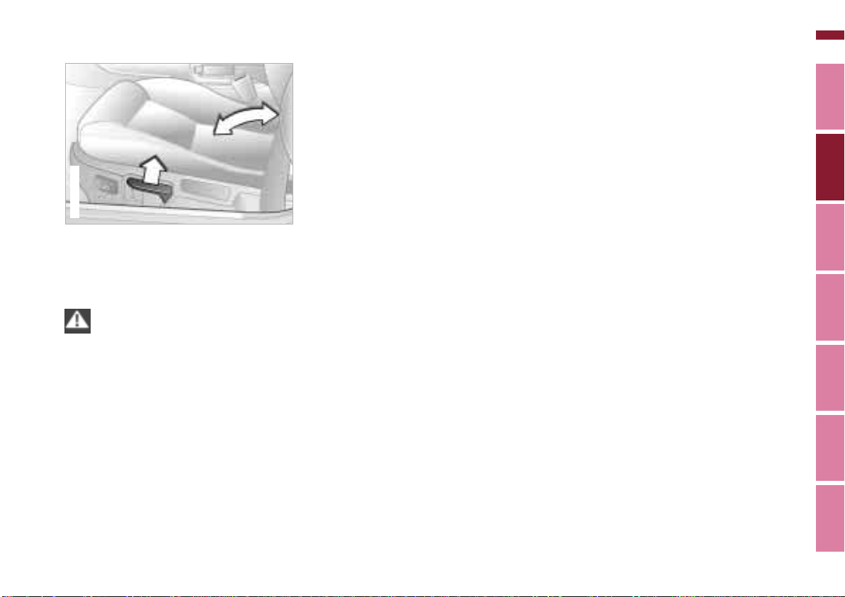
Backrest angle
Pull the lever and apply or remove
weight as required.
Read and comply with the adjust-
ment instructions on page 46.
Failure to do so can result in diminished
personal safety.<
47n
Head restraints
The head restraints are integrated into
the backrests.
Head restraints reduce the risk of spinal
injury in the event of an accident.
Index Data Technology Repiars Car care Controls Overview
Page 48
48n
367de017
Online Edition for Part No. 01 41 0 155 690 - © 09/00 BMW AG
Mirrors
365de030
The mirror on the passenger's
side features a lens with a more
convex surface than the mirror installed
on the driver's side. When estimating
the distance between yourself and
other traffic, bear in mind that the
objects reflected in the mirror are closer
than they appear. This means that estimations of the distance to following
traffic should not be regarded as
precise.<
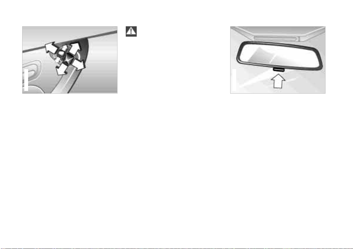
Exterior mirrors
Make adjustments with the large, fourdirectional mirror switch.
Change to the other rearview mirror
with the smaller switch.
> Push the switch up – mirror on the
driver's side.
> Push the switch down – mirror on the
passenger's side.
You can also adjust the mirrors manually by pressing against the outer edges
of their lenses.
Electric defrosting*
Both mirrors are defrosted automatically when the ignition key is in position 2.
Interior rearview mirror
To reduce the glare effect from the rear
while driving at night, tilt the mirror by
moving the small lever.
Vanity mirrors
Fold the sun visors down and push the
cover (coupe only) to the side.
Page 49
367de636
Z3 coupe
Safety belts
Online Edition for Part No. 01 41 0 155 690 - © 09/00 BMW AG
49n
367de018
Drive with your safety belt on
Fasten your safety belt before beginning every trip.
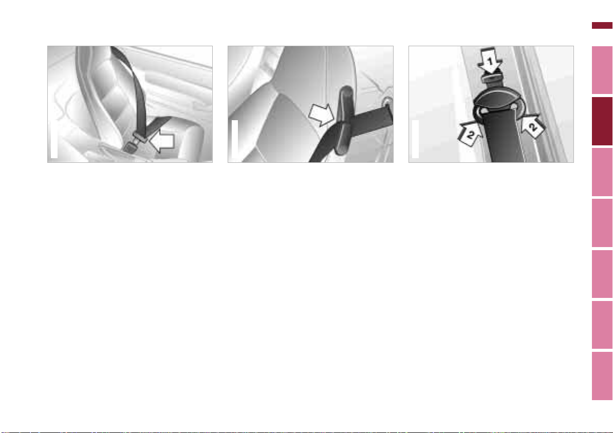
To fasten: make sure you hear the
catch engage in the belt buckle.
To release: press the red button in the
buckle. Hold the belt and guide it back
to its reel.
The safety belt locks:
> In an abrupt stop or a collision.
> If it is pulled out very quickly.
> During sudden braking or accelera-
tion.
> When the vehicle is at an extreme
angle.
367de019
Z3 roadster
Z3 roadster
Make sure the safety belts are routed
through the belt guides on the seat
backrests.
Safety belt height adjustment –
Z3 coupe
You can adjust the safety belts to fit
your own physical dimensions by using
the safety belt height adjustment mechanism.
Downward adjustment:
Press the button down (arrow 1).
Upward adjustment:
Grasp the deflection fitting on the sides
and slide it upward (arrows 2).
Index Data Technology Repairs Car care Controls Overview
Page 50

50n
Online Edition for Part No. 01 41 0 155 690 - © 09/00 BMW AG
Safety belts
Comply with the following instruc-
tions for wearing safety belts. If
you do not, maximum personal protection will not be provided and the safety
function of the belt is limited. These
instructions also apply for vehicle
passengers:
Never allow more than one person to
wear a single safety belt. Never allow
infants or small children to ride in a
passenger's lap.
Avoid twisting the belt while routing it
firmly across your pelvis and shoulder.
Do not route the belt across hard or
fragile objects. Do not route the belt
across your neck, or run it across sharp
edges. Be sure that the belt does not
become caught or jammed.
Avoid wearing bulky clothing which will
prevent proper belt fit. Pull the safety
belt across your shoulders frequently to
re-tension it. In the event of a frontal
impact, a loose lap belt could slide over
your hips, leading to abdominal injury.
In addition, the safety belt's restraint
effectiveness is reduced if the belt is
worn loosely.
Expectant mothers should also wear
their safety belt at all times, taking care
to ensure that the lap belt fits against
the lower hips and does not exert pressure on the abdominal area.<
For care and cleaning, refer to page 132.
If the safety belt system has been
stressed as a result of an accident
or if it has been damaged in any other
way: have the belt system, including the
safety belt tensioner replaced by an
BMW center. In addition, have your
BMW center inspect the safety belt
anchors.
If a child restraint system was in your
vehicle during an accident, consult the
manufacturer's instructions regarding
replacement.<
Page 51
Airbags
Online Edition for Part No. 01 41 0 155 690 - © 09/00 BMW AG
367de730
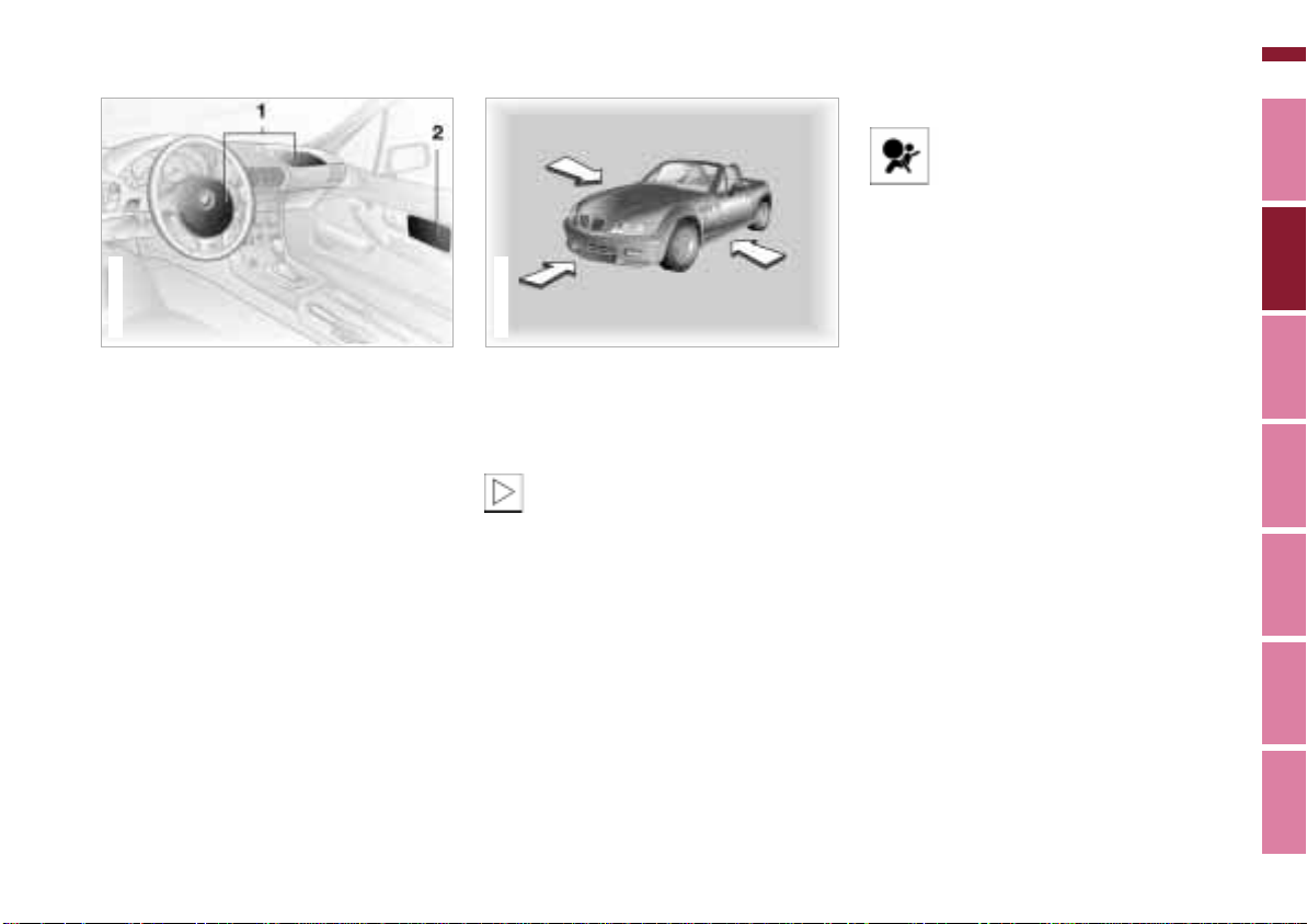
1 Front airbags on the driver and
passenger side
2 Side airbags on the driver and
passenger side
Protective effect
The front airbags help protect the driver
and passenger in the event of a headon collision where the protection
provided by the safety belt alone would
not be adequate. The side airbags help
provide protection in the event of a side
collision. Each side airbag provides
support to the side chest area.
367de736
The illustration depicts schematically
the primary directions of vehicle impact
which initiate airbag deployment.
The airbags will not be triggered in
the event of a minor accident, a
vehicle roll-over, or an impact from the
rear.<
51n
Operational readiness
The indicator lamp on the instrument cluster shows the airbagsystem's operational readiness
starting with ignition key position 1.
System operational:
> The indicator lamp comes on briefly.
System malfunction:
> The indicator lamp fails to come on.
> The indicator lamp comes on briefly
before going out and then lighting up
again.
A system malfunction could prevent the
system from responding to a highintensity frontal impact occurring within
its normal response range.
Please have your BMW center inspect
and repair the system as soon as
possible.
Index Data Technology Repairs Car care Controls Overview
Page 52
52n
367de359
Online Edition for Part No. 01 41 0 155 690 - © 09/00 BMW AG
Airbags
Sitting correctly with airbags
For your safety, comply with the
following instructions for the
airbags. If you do not, the airbags may
not be able to provide their maximum
protection. All passengers in the vehicle
should be aware of and comply with this
information:
The airbags are supplemental restraint
devices designed to provide extra
protection; they are not a substitute for
safety belts. Wear your safety belt at
all times.
Adjust your seat to a position that is
comfortable for you, allowing unrestricted vehicle operation, and is not
closer to the steering wheel than necessary.
Always grasp the steering wheel by the
steering wheel rim, keeping your hands
at the "9-o'clock" and "3-o'clock" positions in order to minimize any risk of
injury to hands or arms if the airbag does
deploy.
There should not be any other people,
animals or objects between the airbag
and the passenger in that seat.
Do not use the cover panel for the front
airbag on the passenger side as a
storage area.
Do not apply adhesive materials to the
cover panels of the airbags, cover them
or modify them in any other way.
If you use a child restraint system, read
carefully and comply with the instructions on page 53.
Be sure that child seats are installed
correctly and with the greatest possible
distance from the airbag in the side trim
panel. Do not allow children to lean out
of the child's seat in the direction of the
side trim panel. Otherwise, serious injuries could occur if the airbag is triggered.<
Even when you have complied with all
of these guidelines, there is still a small
residual risk of minor facial, hand and
arm injuries from airbag deployment
occurring in isolated instances.
The ignition and inflation noise may
cause a mild temporary hearing loss in
extremely sensitive individuals.
Corresponding airbag safety precautions are provided on both sun visors
and the instrument panel (US models).
For additional information concerning
the airbag system, refer to pages 134
and 166.
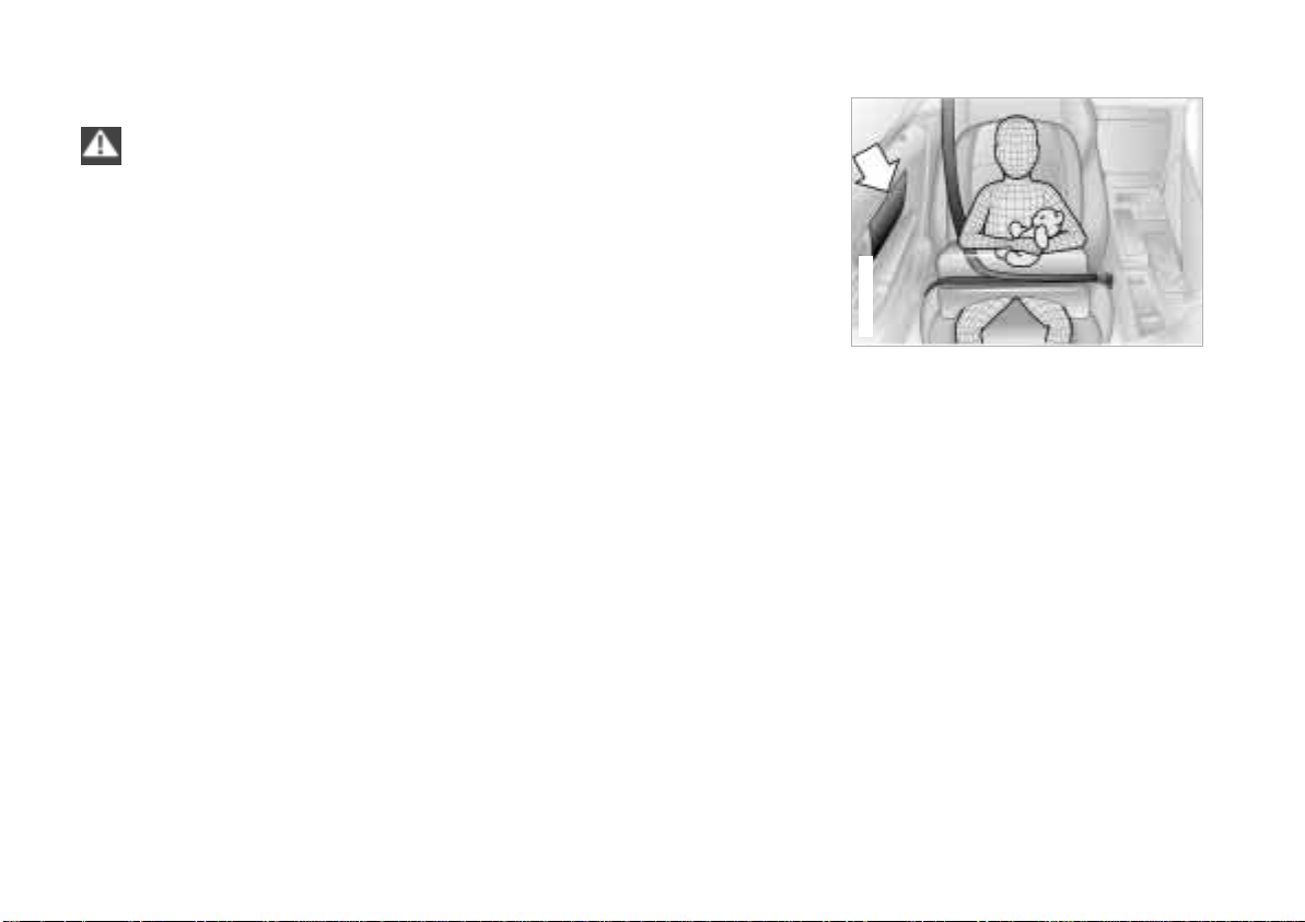
This is the right way a child should sit in
a child restraint when side airbags
(arrow) are provided.
Page 53
Airbags Transporting children safely
Online Edition for Part No. 01 41 0 155 690 - © 09/00 BMW AG
53n
367de360
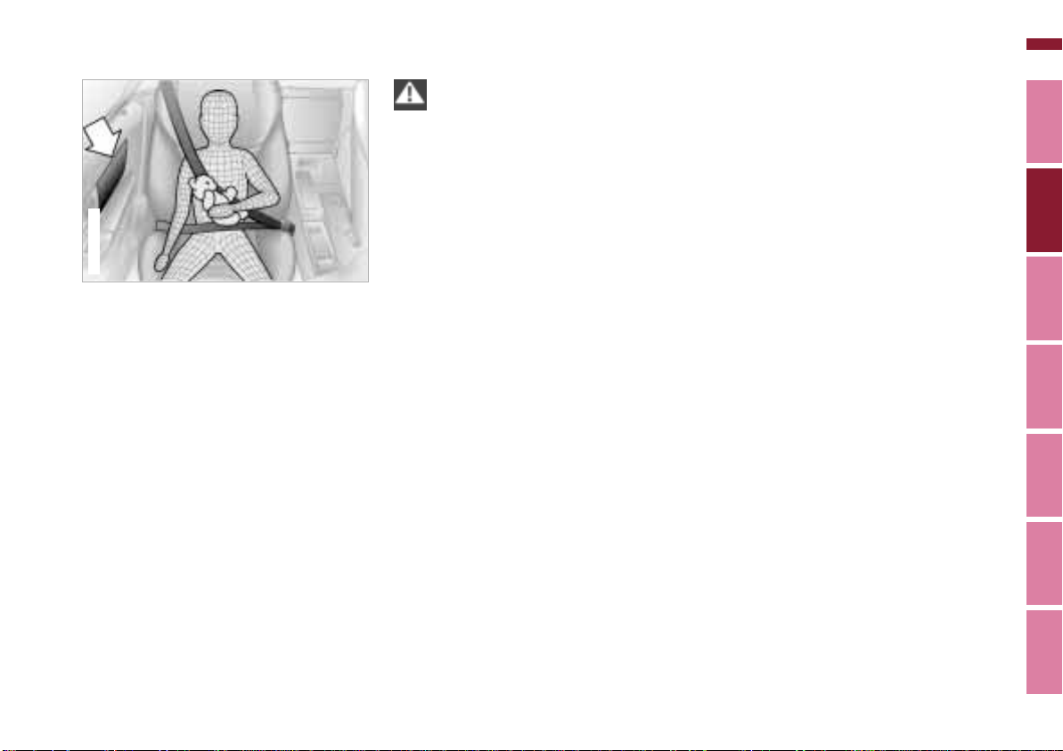
This is the correct way a larger child
should sit wearing the safety belt when
side airbags (arrow) are provided.
Before installing any child restraint
device or child seat, please read
the following:
Never install a rear-facing child restraint
system in the passenger seat of this
vehicle.
If the airbag deploys and hits the backrest of the rear-facing child seat, it is
likely that the child sitting in the rearfacing child seat will be seriously
injured or killed.
If it is necessary for a child (not an
infant) to ride in the vehicle, certain
precautions should be taken. First,
move the passenger seat as far away
from the dashboard as possible. This
important precaution is intended to
maximize the distance between the
airbag and the child. Older children
should be tightly secured with the
safety belt. Younger children should be
secured in an appropriate forwardfacing child restraint system that has
first been secured with a safety belt.
In the interest of the child's safety,
please read carefully and comply with
the instructions for installation and use
provided by the child restraint's manufacturer whenever you use such a
device.
Do not allow children to lean out of a
child restraint system toward the door
or dashboard, as otherwise serious
injuries may result if the airbag deploys.
Always ensure that all occupants (of all
ages) remain properly and securely
restrained at all times.
Read carefully and comply with the
safety precautions covering safety belts
on pages 49, 50. If you do not, the
protective function of the safety belts
will be limited.<
Index Data Technology Repairs Car care Controls Overview
Page 54
54n
367us704
Z3 coupe
Online Edition for Part No. 01 41 0 155 690 - © 09/00 BMW AG
Transporting children safely
367de361
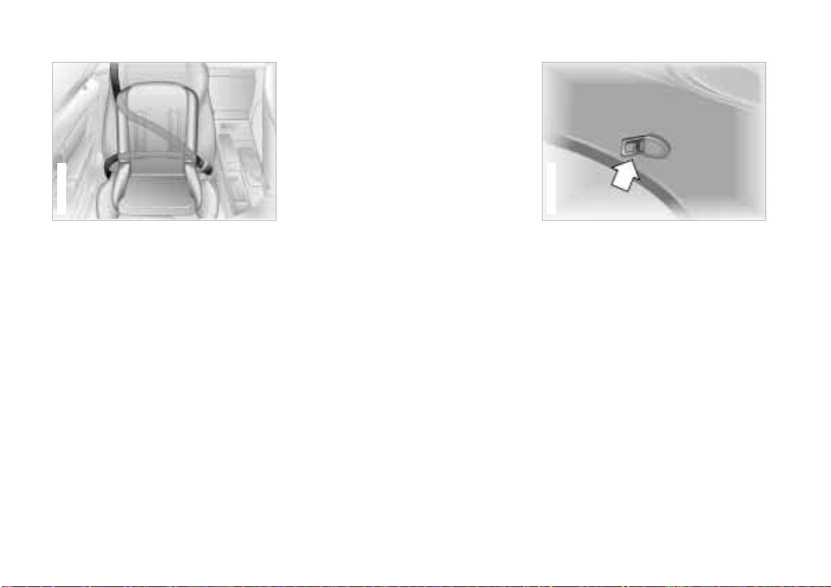
To lock the belt
Extract the entire length of the belt from
the inertia reel mechanism. Allow the
reel to retract the belt somewhat and
engage the buckle, then tighten the belt
against the child restraint system. The
retraction mechanism is now locked.
The belt cannot be retracted further.
Comply with the installation instructions
provided by the manufacturer of the
child restraint system.
Child restraint installation
The safety belt on the passenger side
can be locked for mounting and
securing child restraint systems.
A label with operating instructions is
attached to the belt next to the sliding
latch plate.
To release the belt
Release the buckle, remove the child
restraint system and allow the inertia
reel to retract the belt completely.
Z3 coupe
For the use of child restraint systems
with a tether strap, an additional
mounting point is provided in the coupe
at the right rear on the roof frame.
Attach the tether strap hook to the
mounting point. Adjust the tether strap
according to the child restraint manufacturer's instructions.
Page 55
Steering/Ignition lock
Online Edition for Part No. 01 41 0 155 690 - © 09/00 BMW AG
55n
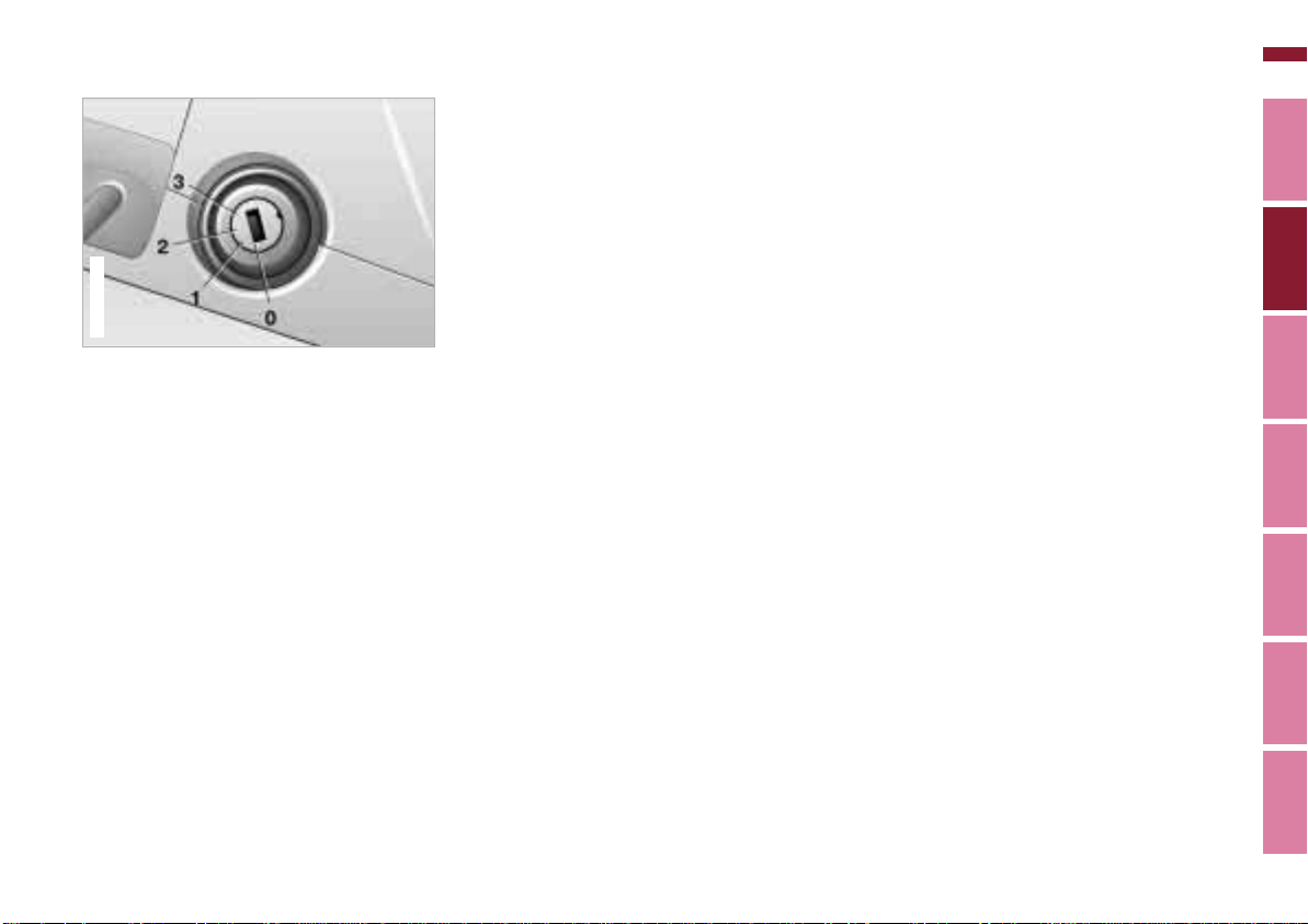
367de009
0 Steering lock engaged
This is the only position in which the
ignition key can be inserted and
removed.
An acoustic warning sounds when you
fail to remove the ignition key after
opening the driver's door.
After removing the key, turn the
steering wheel slightly to the left or right
until you hear the lock engage.
Vehicles with automatic transmission*:
Your vehicle is equipped with an interlock. This means that the ignition key
can not be turned to position 0 and
removed until the selector lever is in
position "P."
Furthermore, the selector lever is
locked in position "P" when the ignition
key is in position 0 or removed from the
ignition switch.
To turn the key back to position 0 or to
remove it, first move the selector lever
to position "P."
1 Steering lock disengaged
You will often find that it is easier to turn
the ignition key from position 0 to 1 if
you move the steering wheel slightly to
help disengage the detent.
Individual electrical equipment and
accessories are available for use.
2 Ignition on
All electrical equipment and accessories are available for use.
3 Starting the engine
Vehicles with manual transmission:
When starting, depress the clutch,
since a lock otherwise prevents the
engine from being started.
Index Data Technology Repairs Car care Controls Overview
Page 56

56n
Online Edition for Part No. 01 41 0 155 690 - © 09/00 BMW AG
Starting the engine
Before starting
> Engage the parking brake.
> Be sure that the transmission
selector is in "Neutral" (or "P" if
vehicle is equipped with automatic
transmission).
> Depress the clutch pedal.
Do not run the engine in enclosed
spaces. The exhaust gases
contain carbon monoxide, an odorless
and colorless, but highly toxic gas.
Breathing the exhaust gases poses an
extreme health risk, and can lead to
unconsciousness and death.
Do not leave the vehicle unattended
with the engine running. An unattended
vehicle with a running engine represents a potential safety hazard.<
Starting the engine
> Start the engine. Do not press the
accelerator pedal.
Do not actuate the starter for too
short a time. Do not turn it for
more than approx. 20 seconds. Release
the ignition key immediately after the
engine starts.
Do not allow the engine to warm up by
allowing it to run while the vehicle
remains stationary. Instead, begin
driving immediately at a moderate
engine speed.<
Should the engine fail to start on the
first attempt (if it is very hot or cold, for
instance):
> Press the accelerator pedal halfway
down while engaging the starter.
Cold starts at very low temperatures,
from approx. +5 7 (–15 6) and at
altitudes above approx. 3,300 ft
(1,000 meters):
> On the first start attempt, engage the
starter for a longer period (approx.
10 seconds).
> Press the accelerator pedal halfway
down while engaging the starter.
If these temperature conditions are
anticipated for a longer period, have the
engine oil changed to a special oil (see
page 122). Please contact your BMW
center for additional information.
Usually, it is not necessary to depress
the accelerator pedal. However, at high
altitudes or in very hot or very cold
weather, depress the pedal halfway
down when starting the engine.
Engine idle speed is controlled by the
engine computer system. Increased
speeds at start-up are normal and
should decrease as the engine warms
up. If engine speed does not decrease,
service is required.
To prevent the battery from
discharging, always switch off any
accessories which are not required.
Switch off the ignition when the vehicle
is not being driven.
Page 57
Switching off the engine Parking brake
Online Edition for Part No. 01 41 0 155 690 - © 09/00 BMW AG
57n
Turn the ignition key to position 1 or 0.
Never withdraw the ignition key
while the vehicle is rolling. The
steering locks and it is impossible to
steer the vehicle.
Always remove the ignition key and
engage the steering lock before leaving
the vehicle.
Vehicles with manual transmission:
Always engage the parking brake when
parking on slopes and inclined
surfaces, since even placing the lever in
1st gear or reverse may not provide
adequate resistance to rolling.
Vehicles with automatic transmission:
Place the selector lever in "Park."<
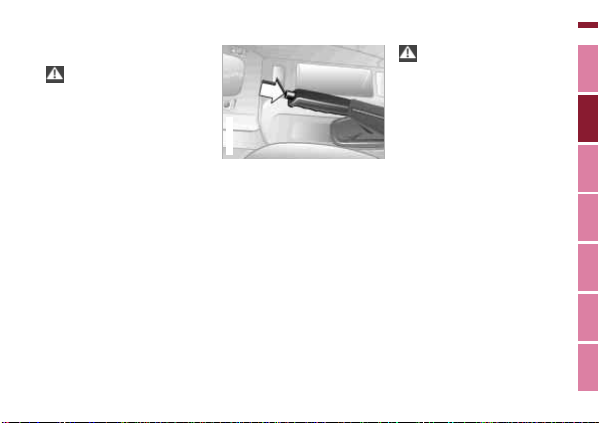
367de028
The parking brake is designed primarily
to prevent the vehicle from rolling when
parked. It operates against the rear
wheels.
To engage
The lock engages automatically when
you lift the lever, and the indicator lamp
in the instrument panel comes on when
the ignition key is in position 2. Refer to
page 21.
To release
Pull up slightly on the lever, press the
button and lower the lever.
If, in exceptional circumstances,
it should be necessary to engage
the parking brake while the vehicle is
in motion, do not pull it with excessive
pressure. Keep your thumb pressed
against the release button while carefully pulling up the lever to apply
moderate pressure.
Excessive pressure can lead to overbraking and loss of traction at the rear
(fishtailing).
The brake lamps do not come on when
the parking brake is engaged.
Vehicles with manual transmission:
Always engage the parking brake when
parking on slopes and inclined
surfaces, since even placing the lever in
1st gear or reverse may not provide
adequate resistance to rolling.
Vehicles with automatic transmission:
Place the selector lever in "Park."<
To avoid corrosion, apply the parking
brake lightly from time to time when
coasting to a standstill (at a traffic
signal, for instance), provided that it is
safe to do so.
Index Data Technology Repairs Car care Controls Overview
Page 58
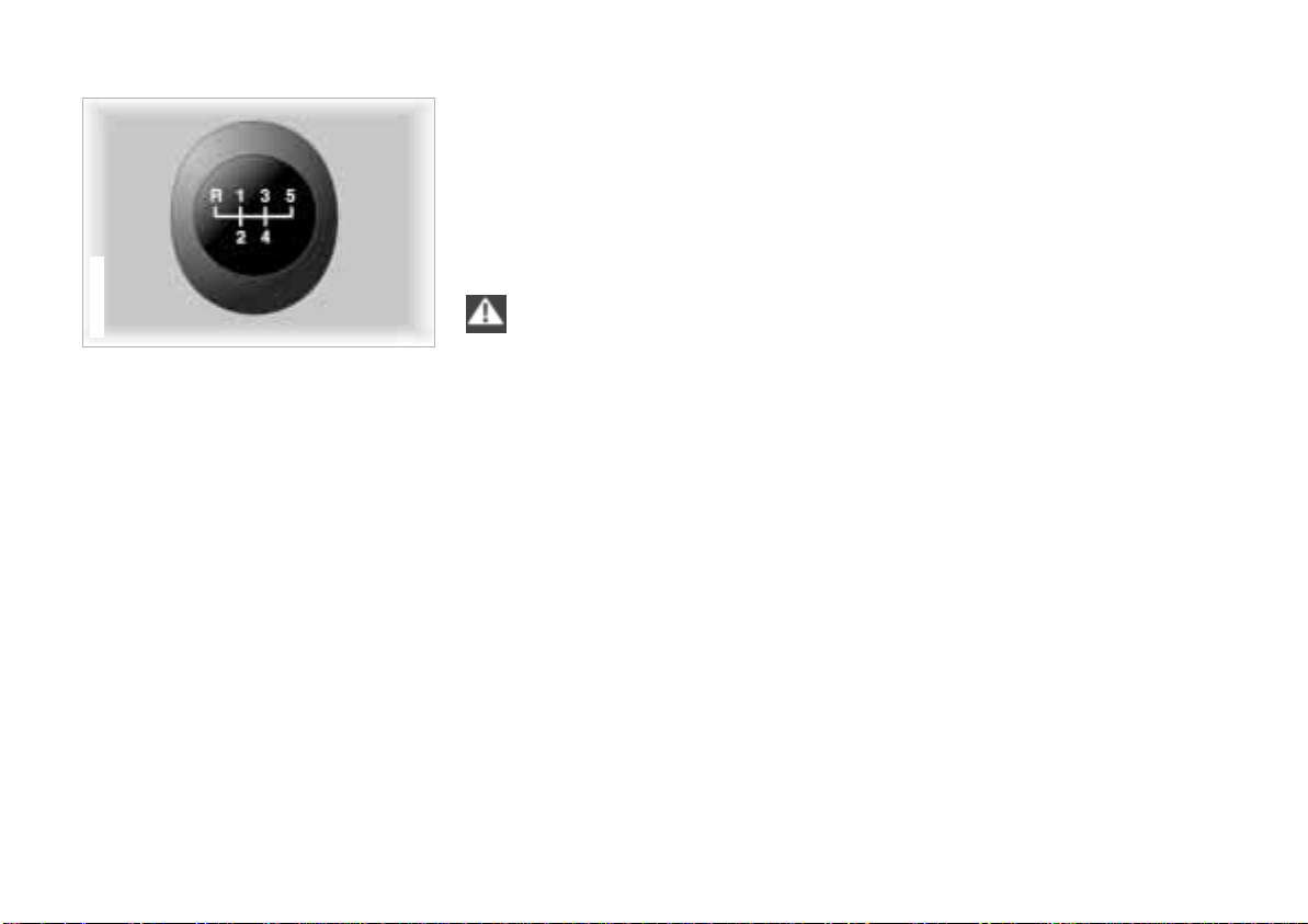
58n
Online Edition for Part No. 01 41 0 155 690 - © 09/00 BMW AG
Manual transmission
367de353
Press the clutch pedal all the way down
each time you shift, pressing the
manual-shift gear lever into its proper
end position.
Depress the clutch when starting the
vehicle, too, otherwise, lockout will
prevent the engine from starting.
The shift lever's neutral plane is located
between 3rd and 4th gear.
When shifting from each gear into
"Neutral," the shift lever returns automatically to this neutral position
because of its spring loading.
Reverse
Select reverse only when the vehicle is
stationary. Press the shift lever to the
left to overcome the resistance.
As you do this, the backup lamps will
turn on automatically when the ignition
key is in position 2.
Do not hold the vehicle in place on
slopes by slipping or "riding" the
clutch. Use the parking brake instead,
otherwise, the ensuing friction to the
clutch plates will cause a great deal of
wear and tear on the clutch.<
Page 59
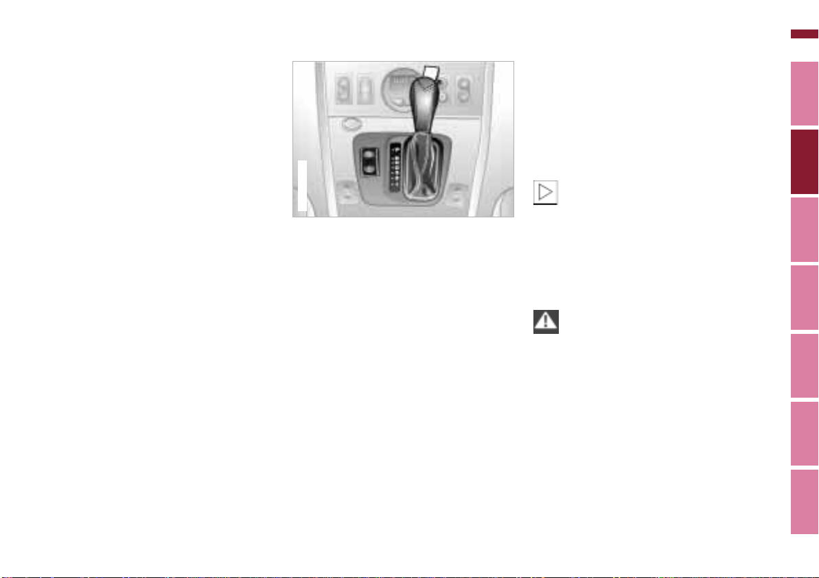
Automatic transmission*
Online Edition for Part No. 01 41 0 155 690 - © 09/00 BMW AG
59n
Adaptive Transmission Control
(ATC)
The automatic transmission of your
BMW is equipped with an Adaptive
Transmission Control (ATC). This
system reacts with precision to your
individual driving style and the current
driving conditions. Different shift
programs are utilized to achieve this.
For details concerning ATC, please refer
to the chapter "Advanced technology"
on page 166.
367us724
Selector lever positions
P R N D 3 2 1
Shift programs
Press the switches:
> E (Economy)
> M (Manual)
Selector lever in position 3:
> S (Sport Program)
Starting the engine
The engine can only be started in
positions "P" or "N."
Range selection
A detent prevents inadvertent shifts to
the "Reverse" or "Park" selector lever
positions. To disengage the detent,
press the button on the front side of the
shift knob (arrow in the illustration on
the left).
While the vehicle is stationary and
before shifting out of "Park" or
"Neutral," depress the footbrake in
order to disengage the selector lever's
lock mechanism (Shiftlock).
Hold the footbrake down until starting
off. The vehicle will otherwise "creep"
when a drive position is engaged.<
Before exiting the vehicle when
the engine is running, place the
selector lever in the "Park" or "Neutral"
position and apply the parking brake.
If you do not, the vehicle can move.
Do not leave the vehicle unattended
with the engine running. An unattended
vehicle with a running engine represents a potential safety hazard. If you
should accidentally select "Neutral"
while traveling at high speed, remove
your foot from the accelerator pedal
immediately. Allow the engine speed to
drop to idle before selecting the desired
drive position. Damage could otherwise
occur due to excessive engine speed.<
Index Data Technology Repairs Car care Controls Overview
Page 60

60n
Online Edition for Part No. 01 41 0 155 690 - © 09/00 BMW AG
Automatic transmission*
P – Park
Select "Park" only when the vehicle is
stationary. The transmission locks to
prevent the rear wheels from turning.
R – Reverse
Select "Reverse" only when the vehicle
is stationary.
N – Neutral
Select "Neutral" only if your journey is
interrupted for a longer period.
D – Drive
(automatic shift program)
This position is designed for driving
under all normal operating conditions.
All forward gears are available; the ATC
is fully operational.
3 – Sport Program
This program is designed for performance-oriented driving. It employs
delayed shift points for full utilization of
the vehicle power reserves.
2 and 1 – Mountain ascents and
engine braking
Select these ranges to prevent undesired shifts and use the engine
braking effect to maximum advantage
on mountain roads or extended uphill
and downhill stretches. The transmission shifts up only as far as the selected
gear.
"Kickdown"
In the "Kickdown" mode, you achieve
the maximum engine performance in
position "D."
Press the accelerator pedal past the
increased resistance point at the fullthrottle position.
E – Economy
For economical driving. This is the initial
position whenever the engine is started.
M – Manual program
This program is for driving conditions
under which the selected gear is to be
retained. The transmission then
remains in this gear both when starting
off and during acceleration. With this
program, you drive only in 4th gear
when in position "D."
Electronic transmission control
module
If the indicator lamp comes on,
there is a malfunction in the
transmission system.
Bring the vehicle to a stop, select transmission position "Park," set the parking
brake and turn the engine off (ignition
key to position 0). Wait a few seconds,
then start the engine.
If the indicator lamp goes out again
after a few seconds, normal transmission performance has been restored.
Continue to drive normally.
If the indicator lamp does not go out, all
selector lever positions can still be
selected. However, the vehicle has
limited performance in the forward drive
positions because the transmission
utilizes only 3rd gear (position 1 or 2) or
4th gear (position 3 or "D").
In this situation, avoid severe loads and
take the vehicle to the nearest BMW
center without delay.
Do not perform service operations
in the engine compartment with a
drive position engaged. If you do so,
the vehicle could move.<
For towing and jump-starting, refer to
pages 160 and 161.
Page 61
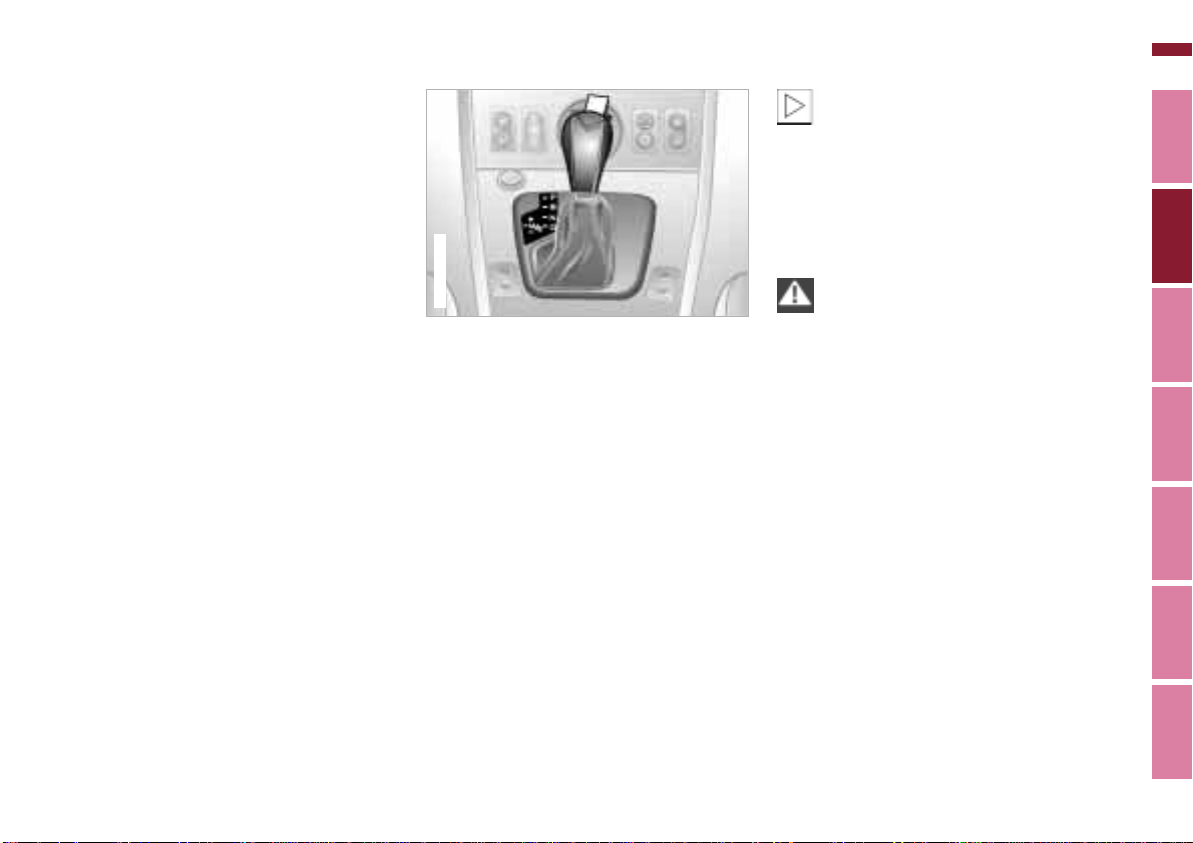
Automatic transmission with Steptronic*
Online Edition for Part No. 01 41 0 155 690 - © 09/00 BMW AG
61n
You can drive as with a normal automatic transmission. In addition, you can
also shift manually.
When you move the selector lever from
the "D" position to the left into the M/S
range, the performance-oriented shift
programs of the automatic transmission
are engaged. As soon as you briefly
touch the selector lever in the "+" or "–"
direction, Steptronic changes the gear.
The manual mode is engaged. When
you wish to use the automatic transmission mode again, move the selector
lever to the right into the "D" position.
The automatic transmission of your
BMW is equipped with Adaptive Transmission Control (ATC), a system which
reacts with precision to your individual
driving style and the driving conditions.
To achieve this, different shift programs
are automatically engaged.
For additional details concerning the
ATC, please refer to the chapter
"Advanced technology" on page 166.
367de703
Selector lever positions
P R N D M/S + –
Starting the engine
The engine can only be started in
selector lever positions P ("Park") or
N ("Neutral").
Range selection
A detent prevents inadvertent shifts to
the "Reverse" or "Park" selector lever
positions. To disengage the detent,
press the button on the front side of
the shift knob (arrow).
While the vehicle is stationary and
before shifting out of "Park" or
"Neutral," depress the footbrake in
order to disengage the selector lever's
lock mechanism (Shiftlock).
Hold the footbrake down until starting
off. The vehicle will otherwise "creep"
when a drive position is engaged.<
If you leave the vehicle with the
engine running, move the selector
lever to the "Park" or "Neutral" position
and apply the parking brake. If you fail
to do this, the vehicle could move.
Do not leave the vehicle unattended
with the engine running. An unattended
vehicle with a running engine represents a potential safety hazard.<
Index Data Technology Repairs Car care Controls Overview
Page 62
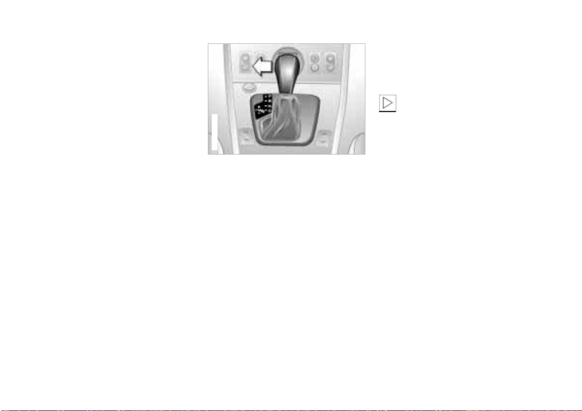
62n
Online Edition for Part No. 01 41 0 155 690 - © 09/00 BMW AG
Automatic transmission with Steptronic*
P — Park
Select "Park" only when the vehicle is
completely stopped. The transmission
locks to prevent the rear wheels from
turning.
R — Reverse
Select "Reverse" only when the vehicle
is completely stopped.
N — Neutral
Select "Neutral" only if your journey is
interrupted for a longer period.
D — Drive
(automatic shift program)
This position is designed for driving
under all normal operating conditions.
All forward gears are available.
"Kickdown"
In the "Kickdown" mode, you achieve
maximum performance.
Depress the accelerator pedal past the
increased resistance point at the fullthrottle position.
367de704
M/S – manual mode and
Sport Program
When you change from D to M/S, the
Sport Program is activated. This is
indicated by "S" in the gear selection
display. The Sport Program is designed
for performance-oriented driving.
With the first brief touch, the automatic
transmission shifts from the Sport
Program to the manual mode. When
you move the selector lever forward in
the "+" direction, the transmission shifts
up. When the lever is moved back in the
"–" direction, the transmission shifts
down. M1 to M5 is indicated in the
transmission range display.
Upshifts or downshifts will only be
carried out by the ATC at appropriate
engine speeds and road speeds. If the
engine speed is too high, for instance,
the downshift will not be executed. The
gear selected will appear briefly in the
instrument cluster followed by the
current gear.
If you are driving in the manual
mode and wish to accelerate
rapidly – to pass another vehicle, for
example – shift down manually or with
the "Kickdown" function.<
You can only change from M/S to
selector lever positions "P," "R" and "N"
via the "D" position.
In the following situations, the Steptronic
"thinks" for you in the manual mode:
> In order to prevent engine over-
speeding, the transmission shifts
automatically to the next higher gear
shortly before the engine speed
cutoff point.
> At low speeds, the transmission
shifts down automatically – you do
not have to act.
> In the "Kickdown" mode, the trans-
mission shifts down to the lowest
possible gear based on the engine
speed.
> Depending on the situation – when
driving in adverse winter conditions,
for example – you may also start out
in 2nd or 3rd gear.
Page 63
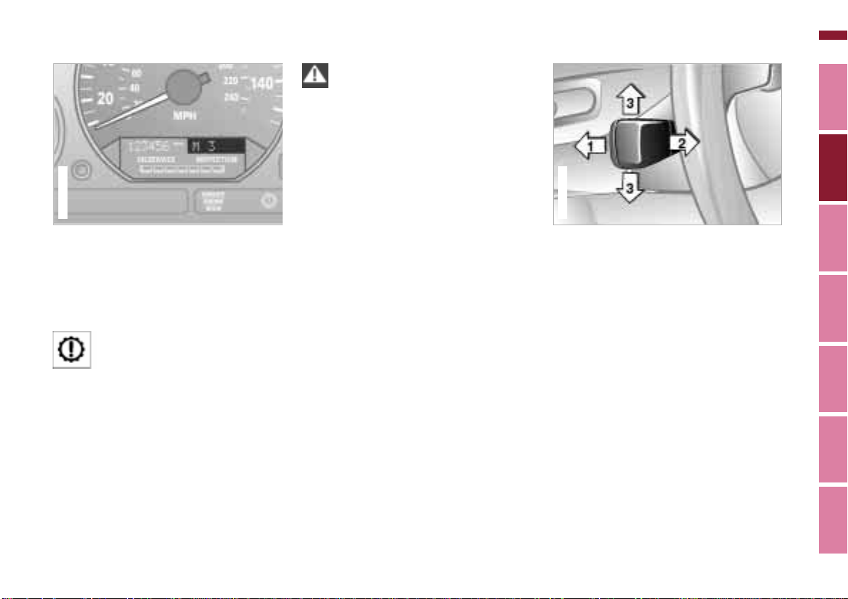
Automatic transmission with Steptronic* Turn signals/High beams
367us024
Online Edition for Part No. 01 41 0 155 690 - © 09/00 BMW AG
Do not work in the engine
compartment when a drive gear
(forward or reverse) is engaged. If you
do so, the vehicle could move.<
Information on jump-starting, towstarting and towing, refer to
pages 160, 161.
367us723
63n
Available displays
S M1 M2 M3 M4 M5
Electronic transmission control
module
If the indicator lamp comes on
there is a fault in the transmission system.
All of the selector lever positions can
continue to be used; in the forward
drive positions, however, the vehicle
will be operating with restricted gear
availability.
If this happens, avoid extreme engine
loads and consult the nearest BMW
center.
1 High beams (blue indicator lamp)
2 Headlamp flasher (blue indicator
lamp)
3 Turn signal indicator (green indicator
lamp and rhythmic clicking of the
relay)
If the indicator lamp and the clicking
from the relay are both faster than
normal, one of the turn indicators has
failed.
To signal briefly
Press the lever up to but not beyond
the detent. It then returns to the center
position when released.
Index Data Technology Repairs Car care Controls Overview
Page 64
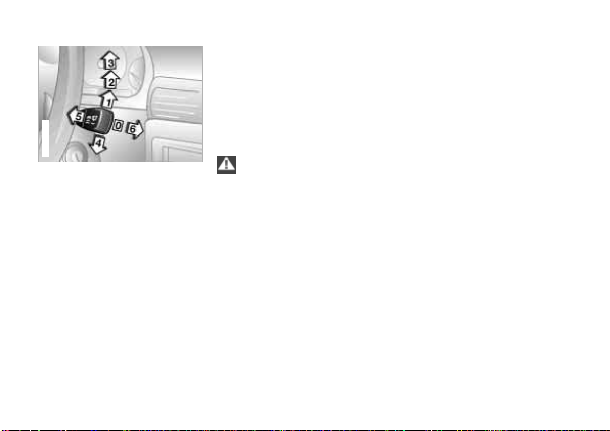
64n
Online Edition for Part No. 01 41 0 155 690 - © 09/00 BMW AG
Wiper/Washer system
367de631
Windshield
0 Wipers retracted
1 Intermittent operation
2 Normal wipe
3 Fast wipe
4 Brief wipe
5 Cleaning the windshield
Rear window – Z3 coupe only
6 Intermittent operation/Cleaning the
rear window
0 Wipers retracted
The wipers are partially hidden behind
the hood. To bring the wipers up into
their vertical position (important when
changing the blades, or folding up
when frost is expected):
Switch on the wipers and switch off the
ignition when the wipers are approximately vertical.
Fold the wipers down onto the
windshield before turning on the
ignition key. Failure to do this could
result in damage to the wiper/washer
system and hood.<
1 Intermittent operation
The length of the interval is varied automatically according to the vehicle's
actual road speed.
2 Normal wiper speed
The wipers automatically revert to intermittent operation when the vehicle is
stationary.
3 Fast wiper speed
When the vehicle is stationary, the
system does not switch to a lower
wiper speed.
4 Brief wipe
The wipers move once across the windshield.
5 Cleaning the windshield
The system sprays washer fluid against
the windshield and activates the wipers
for a brief period.
If you only pull the lever briefly, the
system sprays washer fluid onto the
windshield without activating the
wipers.
Page 65
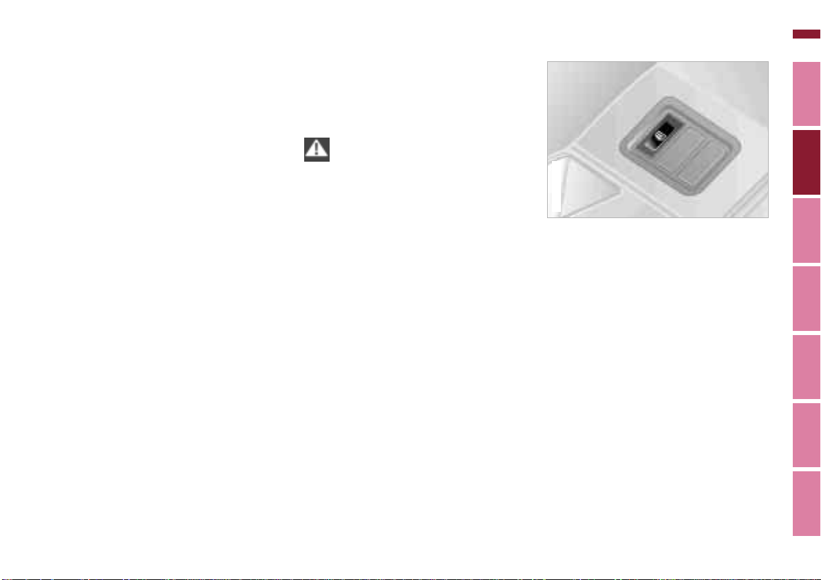
Wiper/Washer system Rear window defroster
367us721
Z3 coupe
Online Edition for Part No. 01 41 0 155 690 - © 09/00 BMW AG
65n
6 Intermittent operation/
Cleaning the rear window
Press the lever briefly:
The intermittent setting of the rear
window wiper is switched on or off.
Press and hold the lever:
The system sprays washer fluid against
the rear window and activates the
wiper. After the lever is released, the
wiper continues to cycle for a few
seconds.
To change the wiper blades, refer to
page 140.
Cleaning the headlamps*
If the headlamps are on, they will also
be cleaned every fifth time you activate
the cleaning the windshield 5 mode.
Do not use the washers if there is
any danger that the fluid will freeze
on the windshield, otherwise vision
could be obscured. For this reason, use
an antifreeze agent. Refer to page 120.
Do not use the washers when the reservoir is empty, otherwise damage to the
washer pump could result.<
Windshield washer jets
The windshield washer jets are heated
automatically
in position 2.
* when the ignition key is
The Z3 coupe is equipped with a rear
window defroster.
To activate
Press the button, the indicator lamp
comes on.
To deactivate
Press the button if the indicator lamp is
on.
Index Data Technology Repairs Car care Controls Overview
Page 66
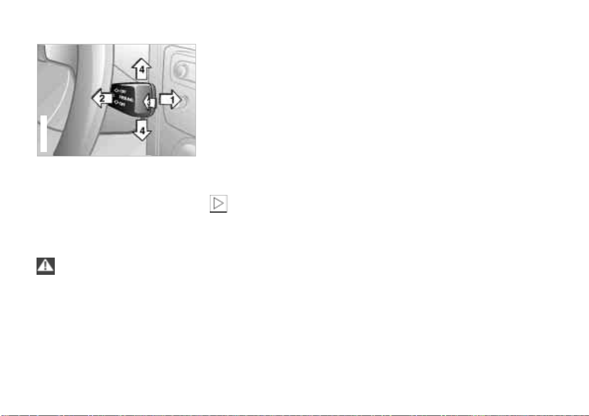
66n
Online Edition for Part No. 01 41 0 155 690 - © 09/00 BMW AG
Cruise control*
365us059
You can store and automatically maintain any desired vehicle speed above
approx. 25 mph (40 km/h).
The system is switched off and the
stored speed deleted from its memory
when you turn the ignition key to position 0.
Do not use the cruise control on
winding roads, when high traffic
density prevents driving at a constant
speed, when the road surface is slick
(snow, rain, ice) or when the road
surface is loose (rocks or gravel,
sand).<
To store and maintain speed/
to accelerate
Press the lever briefly in direction 1:
The system records and maintains the
current vehicle speed. Every time you
briefly press the lever, the speed
increases by approx. 0.6 mph (1 km/h).
Hold the lever in position 1:
The vehicle accelerates without pressure on the accelerator pedal. When
you release the lever, the system
memorizes and maintains the current
speed.
If, on a downhill grade, the engine
braking effect is not sufficient, the
controlled speed can be exceeded.
Speed can drop on uphill grades if the
engine output is insufficient.<
To decelerate
Press the lever briefly in direction 2:
If you are already driving with active
cruise control, the speed is decreased
by approx. 0.6 mph (1 km/h) every time
you briefly touch the lever.
Hold the lever in position 2:
With the cruise control active, the
system automatically reduces the
throttle opening to slow the vehicle.
When you release the lever, the system
memorizes and maintains the current
speed.
Activate stored setting (resume)
Press the lever briefly in direction 3:
The vehicle accelerates to and maintains the last speed stored.
To deactivate
Press the lever briefly in direction 4:
The cruise control is deactivated immediately.
In addition, the system is also automatically deactivated in response to the
following conditions:
> When you apply the brakes.
> When you depress the clutch or move
the automatic transmission selector
lever from "D" to "N".
> If you exceed or fall below the
programmed speed for an extended
period (by depressing the accelerator, for example).
Page 67
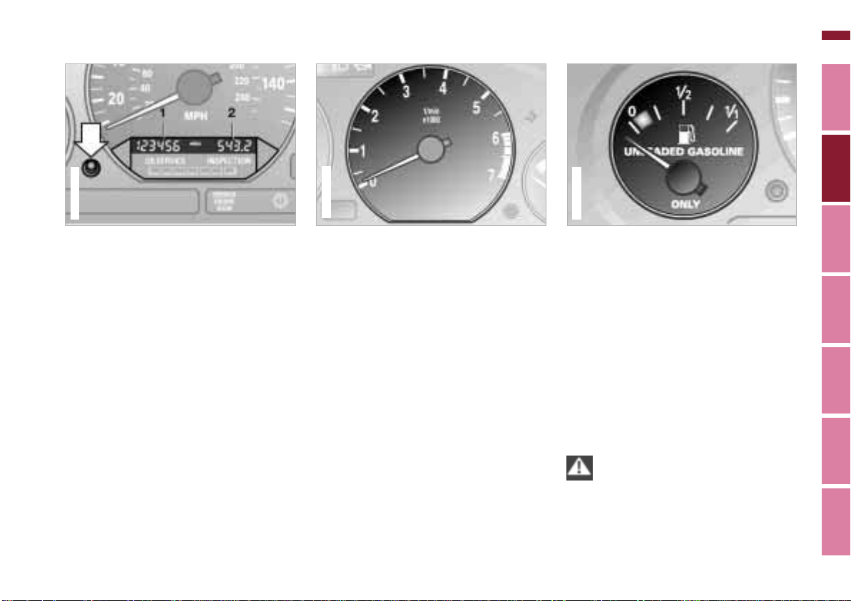
367us006
Odometer Tachometer Fuel gauge
Online Edition for Part No. 01 41 0 155 690 - © 09/00 BMW AG
67n
367us710
1 Odometer
You can activate the displays shown in
the illustration with the ignition key in
position 0 by pressing the button in the
instrument cluster (arrow).
2 Trip odometer/Gear indicator
for automatic transmission with
Steptronic
Trip odometer:
To reset the trip odometer to zero,
press the button (arrow) with the ignition key in position 1 or higher.
Gear indicator:
> S for Sport Program.
> M1 to M5 for manual mode.
*
367de005
Never allow the engine to operate with
the needle in the red overspeed sector
of the gauge.
To protect the engine, the engine
management system automatically
interrupts the fuel supply in this range;
you will notice a loss of power.
When you switch on the ignition, the
indicator lamp comes on briefly to
confirm that the system is operational.
Once the indicator lamp stays on
continuously, there are still approx.
2.1 gallons (8 liters) of fuel in the fuel
tank.
Tank capacity: page 173.
If the tilt of the vehicle varies (extended
driving in mountainous areas, for
example), the needle may fluctuate
slightly.
Please refuel early, since driving
to the last drop of fuel can result in
damage to the engine and/or catalytic
converter.<
Index Data Technology Repairs Car care Controls Overview
Page 68
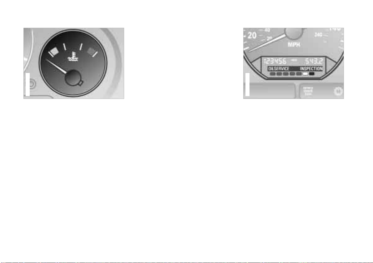
68n
367us709
Online Edition for Part No. 01 41 0 155 690 - © 09/00 BMW AG
Temperature gauge Service Interval Display
Between the blue and red zones
Normal operating range. It is not
unusual for the needle to rise as far as
the edge of the red zone in response to
high outside temperatures or severe
operating conditions.
Checking coolant level: page 123.
367de007
Blue
The engine is still cold. Drive at
moderate engine and vehicle speeds.
Red
When you switch on the ignition, the
warning lamp comes on briefly to
confirm that the system is operational.
Comes on while driving: the engine is
overheated. Switch off the engine
immediately and allow it to cool down.
Green lamps
The number of illuminated lamps
decreases as the time for your next
maintenance visit approaches.
Yellow lamp
This field appears together with
OILSERVICE or INSPECTION.
This alerts you that maintenance is due.
Please arrange for an appointment with
your BMW center.
Red lamp
Maintenance is overdue.
Page 69
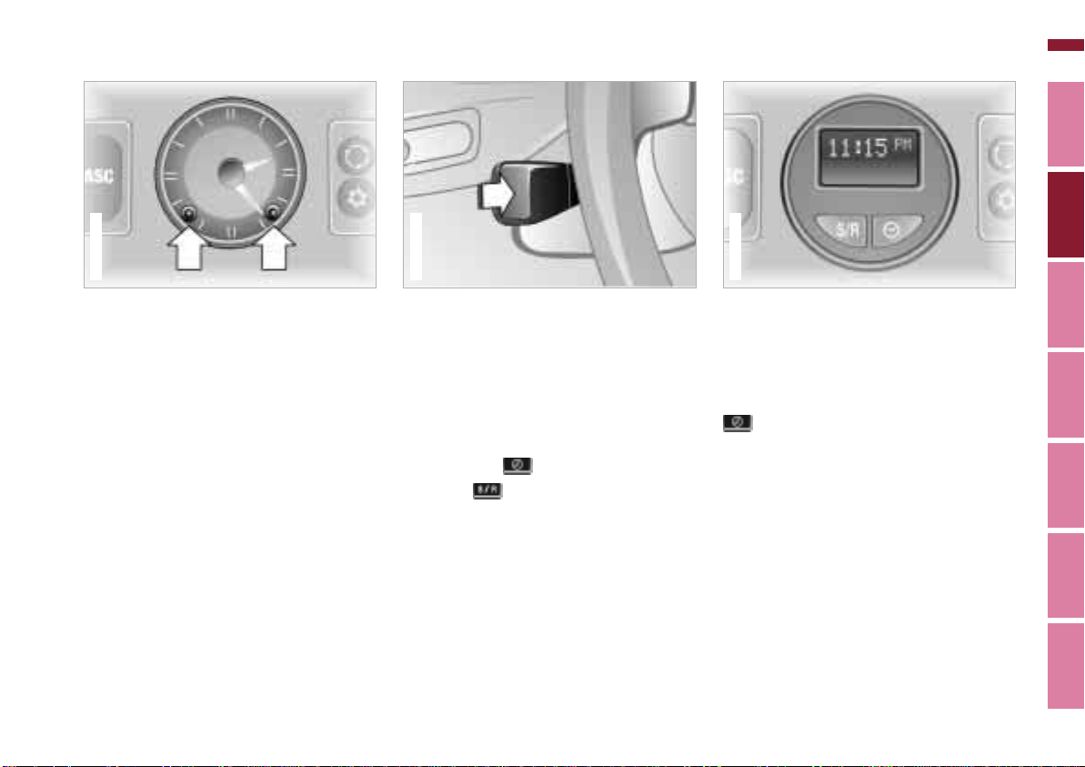
Clock Computer*
367de716
Online Edition for Part No. 01 41 0 155 690 - © 09/00 BMW AG
69n
367de728
You can correct the time by pressing
the buttons (arrows) with a sharp object
such as a ball-point pen.
Set the clock forward by pressing the
right button; set the clock back by
pressing the left button.
367us041
Mode selection
You can call up the computer data in
the display from ignition switch position 1 with the turn indicator lever.
Press the button briefly to select the
next display mode.
In addition, you can display the time by
pressing the key.
With the key, the calculations for
average fuel consumption and speed
are reset and begin again.
Time
The display is provided at ignition key
position 1 and above. In ignition key
position 0, the time is displayed for
approx. 8 seconds by pressing the
key.
Following a power loss, the clock automatically switches to the setting mode:
the colon flashes. Two dashes are
displayed for entering the hour.
Index Data Technology Repairs Car care Controls Overview
Page 70
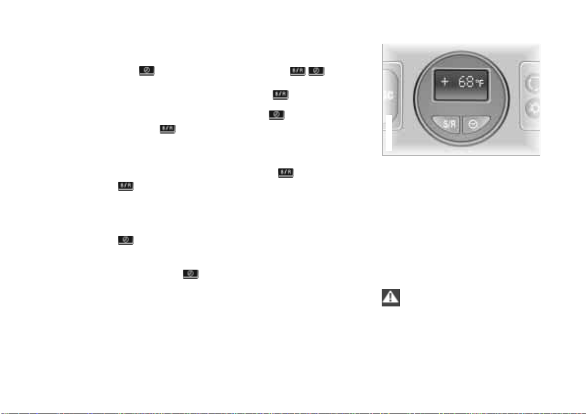
70n
367us712
Online Edition for Part No. 01 41 0 155 690 - © 09/00 BMW AG
Computer*
To enter the time
Enter the numbers for hours and
minutes by pressing the key.
Enter the hour first. Each time the key is
pressed, the hour display increases by
one. Pressing and holding the key
starts the rapid advance.
Confirm the time set with the key.
Now enter the minutes when two zeros
appear.
Enter the minutes in the same manner
as the hours.
Press the save key : the time is
started exactly on the second. The
colon stops flashing.
To reset the time
Press and hold the key for approx.
3 seconds: enter the hour when the
colon begins to flash.
Enter the numbers by pressing the
key in the same manner as when
entering the time.
Setting the 12-hour or 24-hour
mode
Press and hold the keys simultaneously for approx. 1 second.
Then press the key. Now, the mode
changes from 12 to 24 hours whenever
you press the key.
When you select the 12-hour mode,
AM or PM will appear on the right-hand
side of the display panel.
The last mode selected is adopted
when you press or automatically
stored approx. 5 seconds after the last
setting.
Outside temperature
If the outside temperature drops to
approx. +37.5 7 (+3 6), a warning
signal sounds (ice warning). The
temperature display appears automatically and flashes for 8 seconds.
The warning is repeated whenever the
temperature has reached at least
+43 7 (+6 6) and then drops to
+37.5 7 (+3 6) again.
The ice warning does not alter the
fact that surface ice can form at
temperatures above +37.5 7 (+3 6),
on bridges or shaded road surfaces, for
instance.<
Page 71
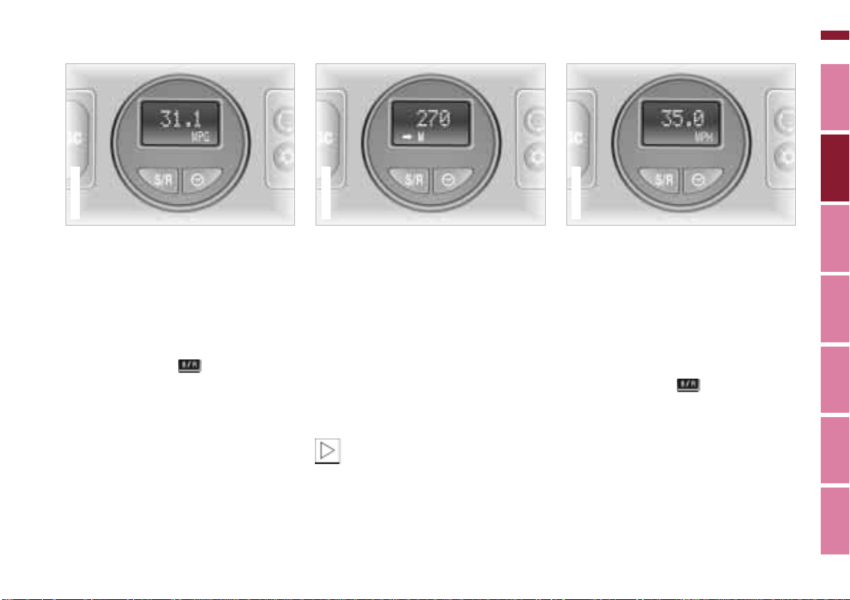
Computer*
367us715
Online Edition for Part No. 01 41 0 155 690 - © 09/00 BMW AG
71n
367us713
Average fuel consumption
The computation is made when the
engine is running. Periods when the
vehicle is parked and the engine is not
running are not included.
New computation:
When this function has been activated
and you press the key, the fuel
consumption is recalculated from that
point in time.
367us714
Estimated cruising range
The computer bases its calculations of
the cruising range on the previous
driving style and on the remaining fuel.
When three dashes flash in the display,
the cruising range is below 9 miles
(15 km). You should refuel as soon as
possible.
Refueling is registered by the computer
with the ignition key in position 1 or
higher.
If the vehicle has been parked at
an angle, the cruising range
cannot be displayed accurately. The
display will be corrected while the
vehicle is moving.<
Average speed
Periods when the vehicle is parked and
the engine is not running are not
included in the computation.
At speeds below 100 mph or 100 km/h,
the display includes decimals.
New computation:
When this function has been activated
and you press the key, the average
speed is recalculated from that point in
time.
Index Data Technology Repairs Car care Controls Overview
Page 72
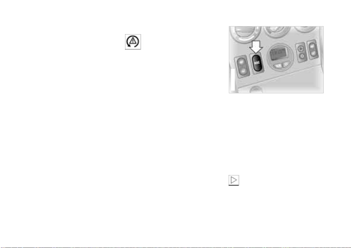
72n
367de701
Online Edition for Part No. 01 41 0 155 690 - © 09/00 BMW AG
Automatic Stability Control plus Traction (ASC+T)
The concept
This system helps provide additional
dynamic stability, particularly when
starting off, accelerating and cornering.
ASC+T recognizes the danger present
in traction loss and will increase driving
stability and traction by reducing the
engine's output, and if necessary, by
applying the brakes individually to the
rear wheels.
ASC+T is available as soon as the
engine starts up.
Indicator lamp
The indicator lamp in the instru-
ment cluster goes out shortly
after you switch on the ignition.
Refer to page 22.
The indicator lamp flashes:
ASC+T controls the drive and braking
forces.
If the indicator lamp fails to go out after
the engine is started, or if it comes on
during normal driving and stays on:
There is a system malfunction or the
system was deactivated with the
button. Consequently, interventions to
increase driving stability (as described
in the preceding column) are not available. You can still drive the vehicle
normally without ASC+T.
In the event of a malfunction, please
consult your BMW center.
Deactivating the ASC+T
Press the button (arrow); the indicator
lamp comes on and stays on.
In the following rare situations, it may
be effective to deactivate the ASC+T
for a brief period:
> When rocking the vehicle or starting
off in deep snow or on loose
surfaces.
> When driving with snow chains.
To maintain vehicle stability, drive
with the ASC+T activated when-
ever possible.<
Page 73
ASC+T Dynamic Stability Control (DSC)*
Online Edition for Part No. 01 41 0 155 690 - © 09/00 BMW AG
73n
Switch the ASC+T on again
Press the button again; the indicator
lamp goes out.
The laws of physics cannot be
repealed, even with ASC+T. It will
always be the driver's responsibility to
drive in a manner that matches road
conditions. We therefore urge you to
avoid using the additional safety margin
of the system as an excuse for taking
risks.<
For additional details concerning
ASC+T, please refer to the chapter,
"Advanced technology," page 167.
The concept
DSC maintains vehicle stability, even in
critical driving situations.
The system optimizes vehicle stability
during acceleration and when starting
from a full stop, as well as optimizing
traction. In addition, it recognizes
unstable vehicle conditions, such as
understeering or oversteering, and, as
far as is possible within the laws of
physics, helps keep the car on a steady
course by reducing the engine speed
and brake applications to the individual
wheels.
The DSC is operational every time you
start the engine. DSC includes the
functions of ADB and CBC, refer to
page 100.
The ADB (Automatic Differential
Braking) copies the function of conventional differential and transverse locks
through brake intervention, and
increases traction whenever conditions
merit, e.g. when driving on snowcovered roads.
If the DSC is switched off the ADB is
still in ready mode.
Indicator lamp
The indicator lamp in the instrument cluster goes out shortly
after you switch on the ignition.
Refer to page 22.
The indicator lamp flashes:
ASC+T controls the drive and braking
forces.
The indicator lamp stays lit:
DSC has been switched off via the
button; ADB is in ready mode.
ADB control intervention is not indicated.
The indicator lamp and the
brake warning lamp remain on:
The DSC, ADB and DBC have
been switched off via the button
or are defective.
The vehicle will remain completely
operational, however without DSC. In
the event of a fault, please see your
BMW center.
Indicator and warning lamps for
Canadian models.
Index Data Technology Repairs Car care Controls Overview
Page 74
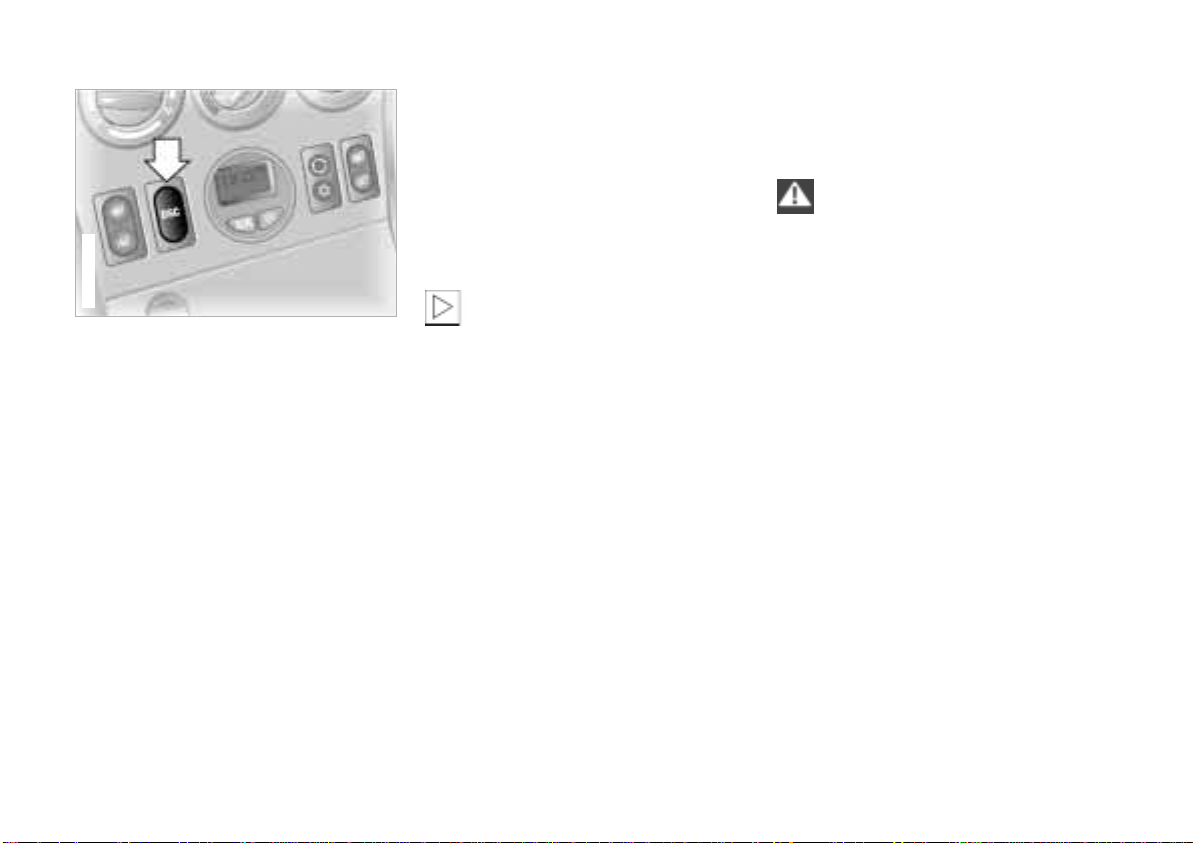
74n
Online Edition for Part No. 01 41 0 155 690 - © 09/00 BMW AG
Dynamic Stability Control (DSC)*
367de739
Switch the DSC off/activate the
ADB
Press the DSC switch (arrow) – the indicator lamp comes on and remains on.
DSC has been switched off; ADB is in
ready mode.
In the following exceptional circumstances, it may be effective to activate
the ADB for a short period:
> When rocking the vehicle or starting
off in deep snow or on loose surfaces
> When driving on snow-covered
grades, in deep snow, or on a snowcovered surface that has been
packed down from being driven on
> When driving with snow chains.
Switch the DSC and ADB off
Hold the DSC switch down for at least
3 seconds. The indicator lamp and the
red warning lamp for the brake
hydraulic system remain on.
In this case, no interventions to
increase stability and traction for
engine and brakes are carried out.
To maintain vehicle stability, drive
with the DSC activated whenever
possible.<
Switch the DSC and ADB back on
Press the button again; the indicator
lamp or the indicator lamps will go out.
The laws of physics cannot be
repealed, even with DSC. It will
always be the driver's responsibility to
drive in a manner that matches road
conditions. We therefore urge you to
avoid using the additional safety margin
of the system as an excuse for taking
risks.
The DSC is deactivated and will not
carry out any stabilizing intervention
when the ADB is in ready mode.
Do not make any modifications to the
DSC system. Allow only authorized
technicians to perform service procedures on the DSC.<
You will find additional details
concerning DSC in the chapter
"Advanced technology" on page 167.
Page 75
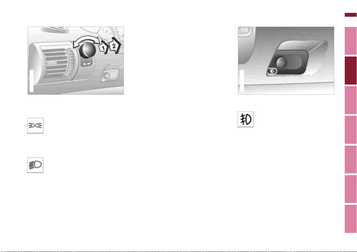
Parking lamps/Low beams Fog lamps
367us023
Online Edition for Part No. 01 41 0 155 690 - © 09/00 BMW AG
"LIGHTS ON" warning
When you open the driver's door after
turning the ignition key to position 0,
a warning signal sounds for a few
seconds to remind you if the headlamps
have not been switched off.
Daytime running lamps*
The headlamps are automatically
367us021
switched on for daylight driving at
ignition key position 2.
75n
Parking lamps (position lamps/
side marker lamps)
Position 1
With the switch in this position,
vehicle lighting on both sides is
on.
Low beam headlamps
Position 2
When you switch the ignition off
while the low beams are still on,
only the parking lamps (position lamps/
side marker lamps) remain on.
Instrument panel lighting
In order to adjust the illumination
intensity, turn the pulled switch.
Front fog lamps*
A green indicator lamp comes
on in the instrument cluster to
indicate that the front fog lamps
are on.
It is not possible to switch on the front
fog lamps together with the high
beams.
Index Data Technology Repairs Car care Controls Overview
Page 76
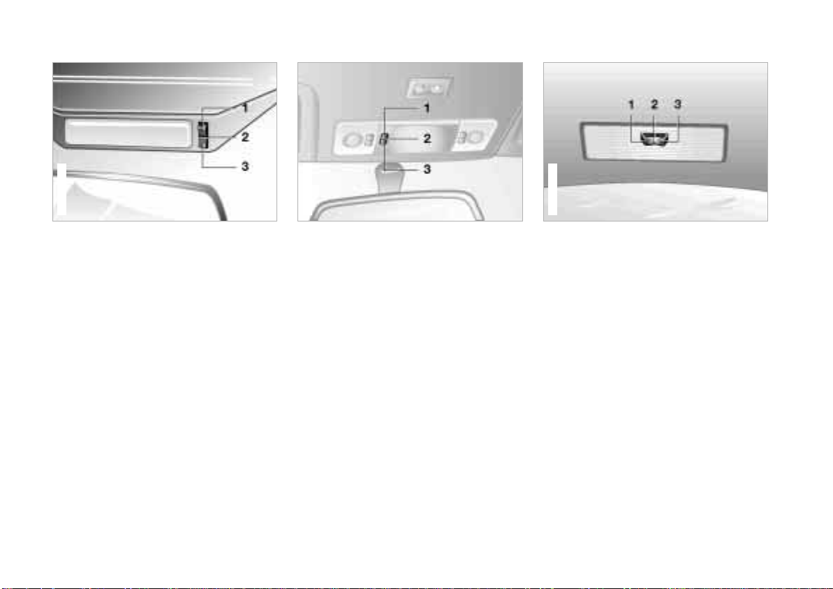
76n
367de626
Z3 coupe
Online Edition for Part No. 01 41 0 155 690 - © 09/00 BMW AG
Interior lamps
367de026
Z3 roadster
1 Continuously off
2 Automatically controlled
3 Continuously on
Z3 roadster
367de617
Z3 coupe – front
1 Continuously on
2 Continuously off
3 Automatically controlled
Z3 coupe
Z3 coupe – rear
1 Continuously on
2 Continuously off
3 Automatically controlled
Page 77
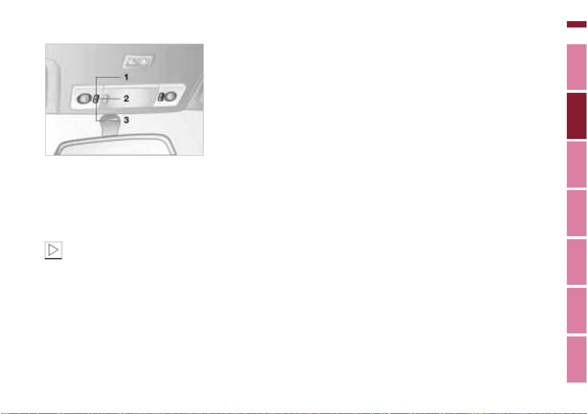
Reading lamps
Online Edition for Part No. 01 41 0 155 690 - © 09/00 BMW AG
77n
367de618
The Z3 coupe is equipped with reading
lamps:
1 Continuously on
2 Continuously off
3 Automatically controlled
In order to conserve the battery,
all of the lamps in the vehicle are
switched off automatically about
15 minutes after the ignition key is
turned to position 0.<
Z3 coupe
Index Data Technology Repairs Car care Controls Overview
Page 78
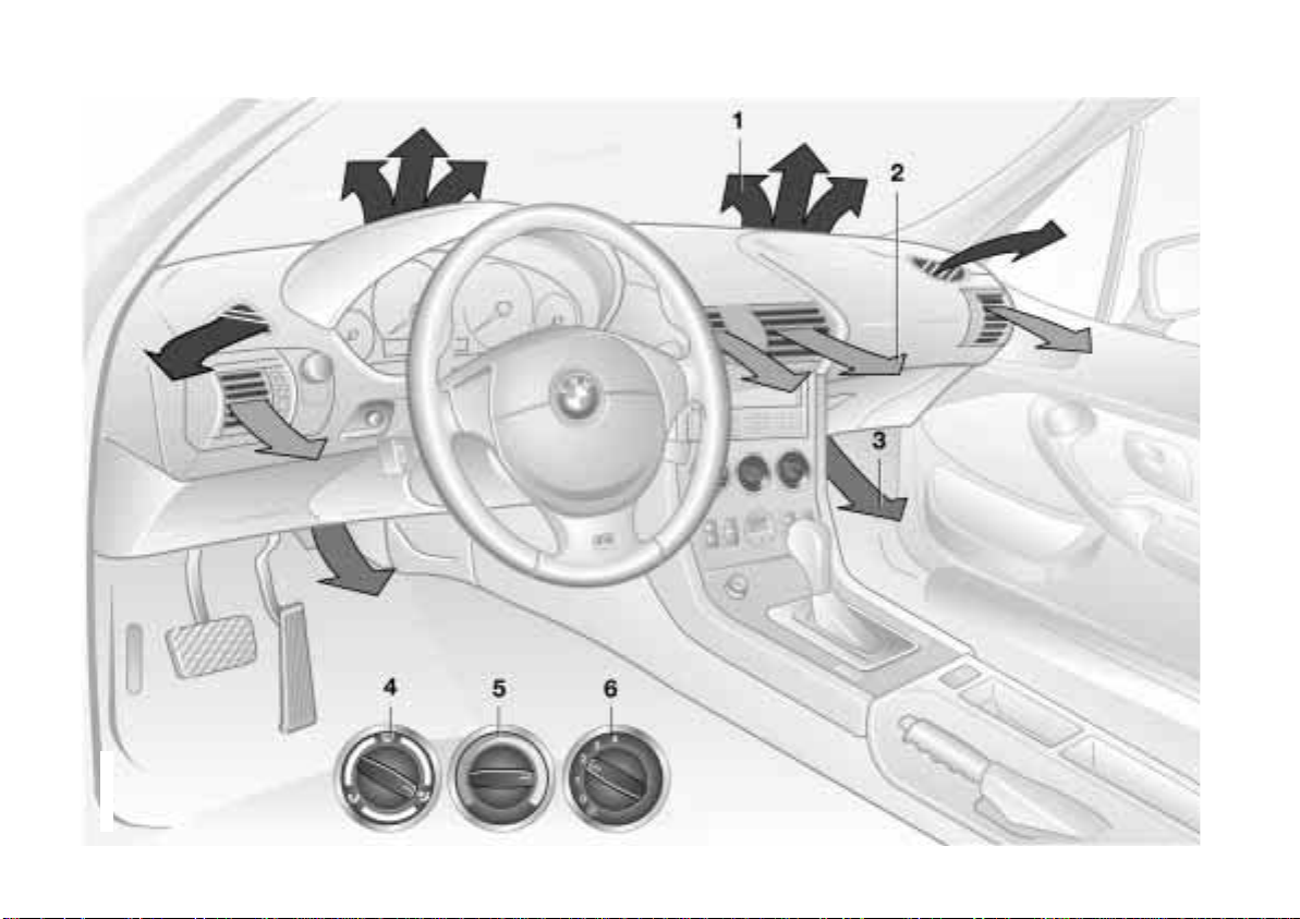
78n
Online Edition for Part No. 01 41 0 155 690 - © 09/00 BMW AG
Heating and ventilation
367de715
Page 79

Heating and ventilation
Online Edition for Part No. 01 41 0 155 690 - © 09/00 BMW AG
1 Air flow toward the windshield and
side windows
2 Air flow toward upper body
The rotary dials allow infinitely-variable regulation of the air supply. You
can change the airflow direction with
the lever in the center of the vent or
by rotating the vent grille 80
3 Front footwell ventilation
4 Air distribution onto the
> windows
> upper body
> footwell
All intermediate settings are
possible 80
5 Temperature 80
6 Air supply
The heating and ventilation are oper-
ational beginning with position 1 80
79n
Index Data Technology Repairs Car care Controls Overview
Page 80
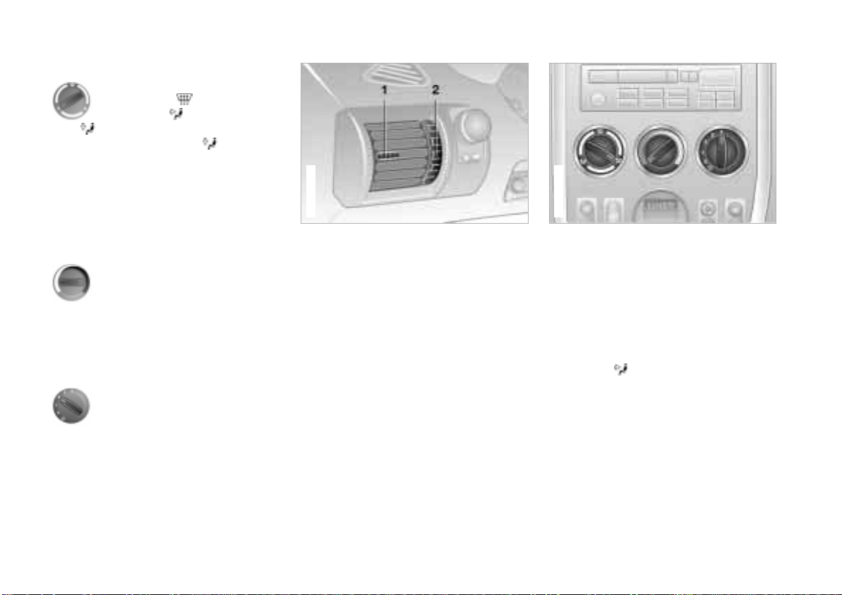
80n
367de705
Online Edition for Part No. 01 41 0 155 690 - © 09/00 BMW AG
Heating and ventilation
Air distribution
You can direct the air flow onto
the windows , toward the
upper body and into the footwell . All intermediate settings are
possible. In this position , a small
volume of air is directed onto the
windows in order to keep them free of
condensation.
A "6 o'clock" position is recommended
as the normal operating setting.
367de224
Temperature
In order to increase the temper-
ature of the passenger compart-
ment, turn to the right (red). For
rapid heating, turn completely to the
right. Then select an interior temperature which is pleasant for you.
Air supply
You can select blower speeds
from 1 to 4. Both heating and
ventilation become more effective as the air flow rate is increased. In
position 0, the blower and the heater
are switched off.
Draft-free ventilation
The outlets for the occupants' upper
body area can be adjusted to suit your
personal preferences:
Use the rotary dial (2) to open and close
the vent throughout an infinitely-variable range. With the levers (1), you can
direct the air flow to the side. Adjust the
air flow up or down by rotating the vent
grill.
Set the outlets so that the air flows past
you and is not directed straight at you.
Rapid ventilation
1 Set the blower speed control for the
air flow rate to position 4.
2 Turn the rotary temperature control
completely to the left (blue). Then
select an interior temperature which
is pleasant for you.
3 Rotary control for air distribution in
position .
4 Open the outlets for the upper body
area.
Page 81
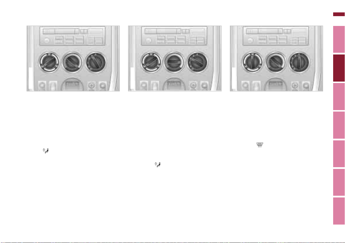
Heating and ventilation
367de708
Online Edition for Part No. 01 41 0 155 690 - © 09/00 BMW AG
81n
367de706
Rapid heating
1 Set the blower speed control for the
air flow rate to position 3.
2 Turn the rotary temperature control
completely to the right (red). Then
select an interior temperature which
is pleasant for you.
3 Rotary dial for air distribution in posi-
tion .
367de707
Heating
This setting is recommended if the
windows are free of ice or condensation:
1 Set the blower speed control for the
air flow rate to position 2.
2 Use the rotary temperature control to
select an interior temperature which
is pleasant for you.
3 Rotary control for air distribution in
position .
To defrost the windows and
remove condensation
1 Set the blower speed control for the
air flow rate to position 4.
2 Turn the rotary temperature control
completely to the right (red).
3 Rotary control for air distribution in
position .
4 To defrost the rear window on the
coupe, switch on the rear window
defroster.
Index Data Technology Repairs Car care Controls Overview
Page 82
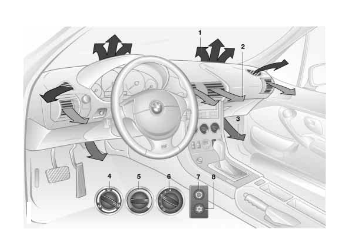
82n
Online Edition for Part No. 01 41 0 155 690 - © 09/00 BMW AG
Heating and ventilation/Air conditioner*
367de714
Page 83

Heating and ventilation/Air conditioner*
Online Edition for Part No. 01 41 0 155 690 - © 09/00 BMW AG
1 Air flow toward the windshield and
side windows
2 Air flow toward upper body
The rotary dials allow infinitely-variable regulation of the air supply. You
can change the airflow direction with
the lever in the center of the vent or
by rotating the vent grille 85
3 Front footwell ventilation
4 Air distribution onto the
> windows
> upper body
> footwell
All intermediate settings are
possible 84
5 Temperature 84
6 Air supply
The heating and ventilation are oper-
ational beginning with position 1 84
7 Recirculated air mode 84
8 Air conditioner 84
83n
Index Data Technology Repairs Car care Controls Overview
Page 84

84n
Online Edition for Part No. 01 41 0 155 690 - © 09/00 BMW AG
Heating and ventilation/Air conditioner*
Air distribution
You can direct the flow of air
onto the windows , toward
the upper body and into the
footwell . All intermediate settings
are possible. In position , a small
volume of air is directed onto the
windows in order to keep them free of
condensation.
A "6 o'clock" position is recommended
as the normal operating setting.
Temperature
In order to increase the temper-
ature of the passenger compart-
ment, turn to the right (red). For
rapid heating, turn completely to the
right. Then select an interior temperature which is pleasant for you.
Air supply
You can select blower speeds
from 1 to 4. Both heating and
ventilation become more effective as the air flow rate is increased. In
position 0, the blower and the heater
are switched off.
Air conditioner
The air is cooled and dehumidified and – depending on the
temperature setting – warmed
again when the air conditioner system
is switched on. Depending on the
weather, the windshield may fog over
briefly when the engine is started.
At outside temperatures below approx.
41 7 (+5 6), switch off the air conditioner. This will help to prevent the
windows from fogging up.
If the windows fog over after switching
the air conditioner off, switch it on
again.
Condensation forms in the air
conditioner system during operation, which then exits under the vehicle.
Traces of condensed water of this kind
are thus normal.<
Recirculated air mode
If there are unpleasant odors in
the outside air, you can tempo-
rarily block the flow of air. The
system then recirculates the air
currently within the vehicle.
If the windows fog over in the
recirculated air mode, switch this
mode off and increase the air supply as
required.<
Page 85
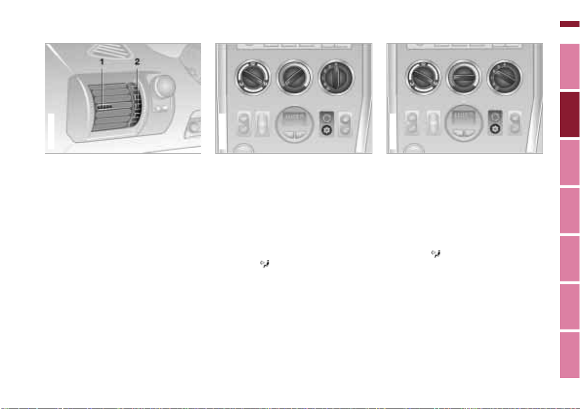
Heating and ventilation/Air conditioner*
367de710
Online Edition for Part No. 01 41 0 155 690 - © 09/00 BMW AG
85n
367de224
Draft-free ventilation
The outlets for the occupants' upper
body area can be adjusted to suit your
personal preferences:
Use the rotary dial (2) to open and close
the vent throughout an infinitely-variable range. With the levers (1) you can
direct the air flow to the side, and up or
down by rotating the vent grill.
Set the outlets so that the air flows past
you and is not directed straight at you.
367de709
Rapid ventilation
1 Set the blower speed control for the
air flow rate to position 4.
2 Switch on the air conditioner
3 Turn the rotary temperature control
completely to the left (blue). Then
select an interior temperature which
is pleasant for you.
4 Rotary control for air distribution in
position .
5 Open the outlets for the upper body
area.
*.
Cooling
1 Set the blower speed control for the
air flow rate to position 2.
2 Switch on the air conditioner
3 Use the rotary temperature control to
select an interior temperature which
is comfortable for you.
4 Rotary control for air distribution in
position .
5 Open the outlets for the upper body
area.
*.
Index Data Technology Repairs Car care Controls Overview
Page 86
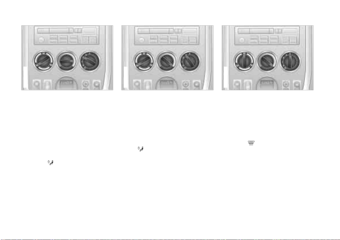
86n
367de713
Online Edition for Part No. 01 41 0 155 690 - © 09/00 BMW AG
Heating and ventilation/Air conditioner*
367de711
Heating
This setting is recommended if the
windows are free of ice and condensation:
1 Set the blower speed control for the
air flow rate to position 2.
2 Use the rotary temperature control to
select an interior temperature which
is pleasant for you.
3 Rotary control for air distribution in
position .
367de712
Rapid heating
1 Set the blower speed control for the
air flow rate to position 3.
2 Turn the rotary temperature control
completely to the right (red). Then
select an interior temperature which
is pleasant for you.
3 Rotary dial for air distribution in posi-
tion .
To defrost the windows and
remove condensation
1 Set the blower speed control for the
air flow rate to position 4.
2 Turn the rotary temperature control
completely to the right (red).
3 Rotary control for air distribution in
position .
4 To defrost the rear window on the
coupe, switch on the rear window
defroster.
Page 87
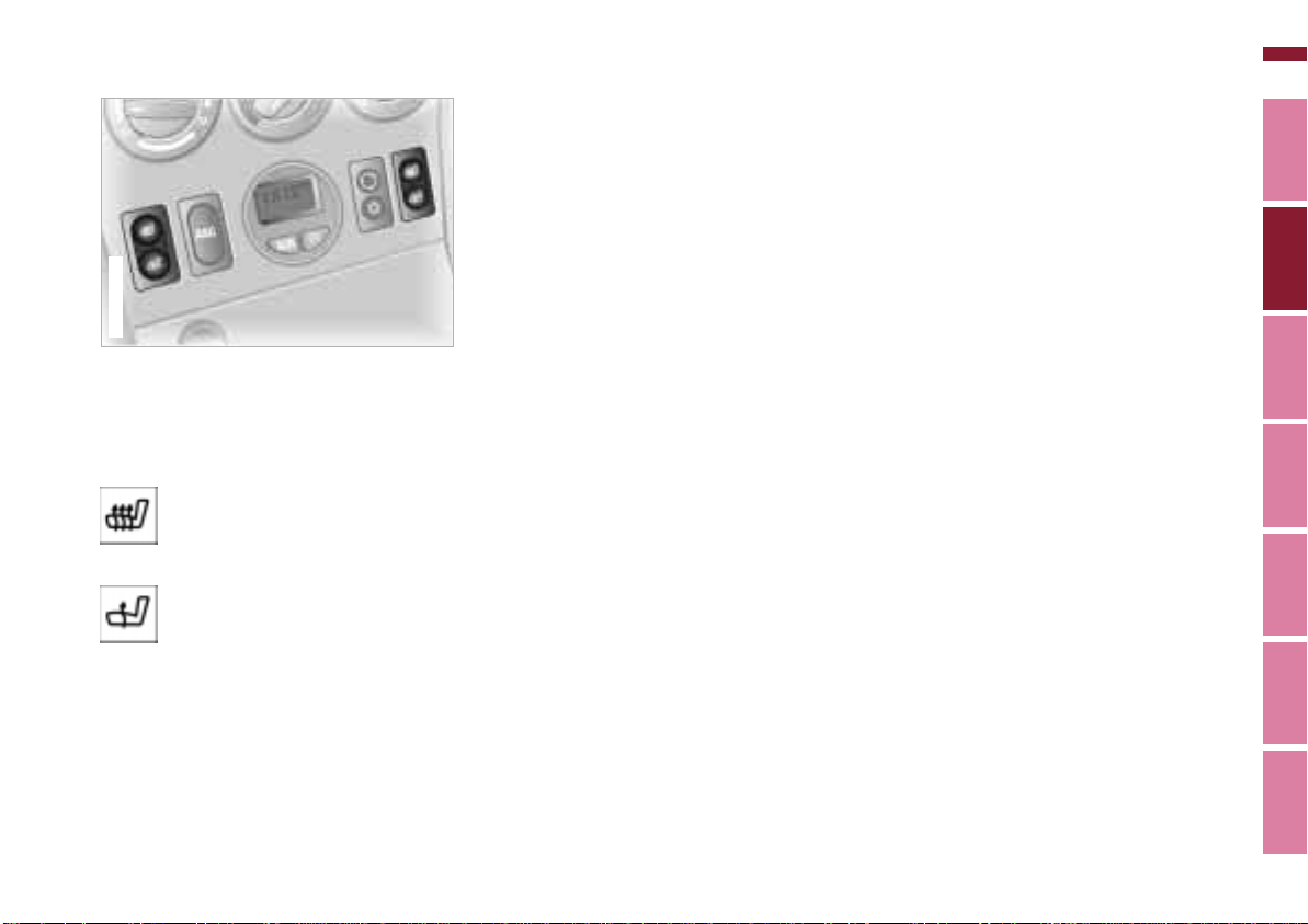
Seat heating*
Online Edition for Part No. 01 41 0 155 690 - © 09/00 BMW AG
367de732
The seat cushion and backrest can be
heated at ignition key position 2.
Press the switches with the heating
symbols:
Rapid heating as long as the
switch comes on brightly. Automatic changeover to regular
heating.
Heating as long as the switch
comes on brightly. Heating
switches off automatically.
To switch over while heating: press the
section of the switch that is dimly lit.
To switch off early: press the section of
the switch that is brightly lit.
87n
Index Data Technology Repairs Car care Controls Overview
Page 88
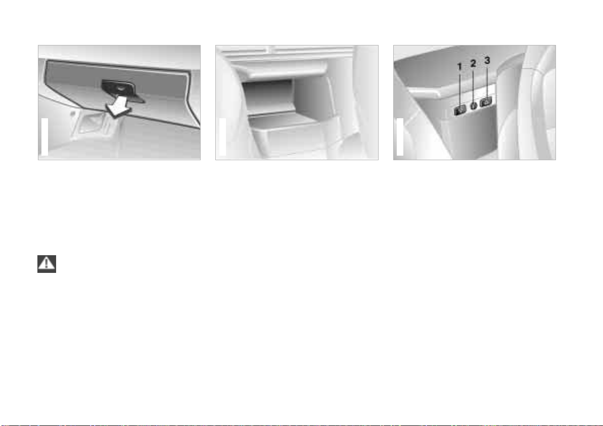
88n
367de035
Z3 roadster
Online Edition for Part No. 01 41 0 155 690 - © 09/00 BMW AG
Glove compartment Additional storage areas Storage boxes*
367us034
To open
Pull the handle and push down the
door.
To close
Push the door up.
To prevent injury in the event of
an accident, close the glove
compartment immediately after use.<
367de316
Storage compartments are located in
the center console, in the doors and, on
the Z3 coupe, between the backrests
(refer to the illustration).
A coin box
pocket on the driver's side.
A storage net is mounted on the
passenger side of the center console.
* is located in the door
Z3 coupe
The Z3 roadster has locking storage
*:
boxes
Small storage box
Press button 1 to open the box.
Large storage box
Press button 3 and lift the lid of the box.
Both of the storage boxes can be
locked with the master keys (refer to
page 30) at lock 2.
Page 89
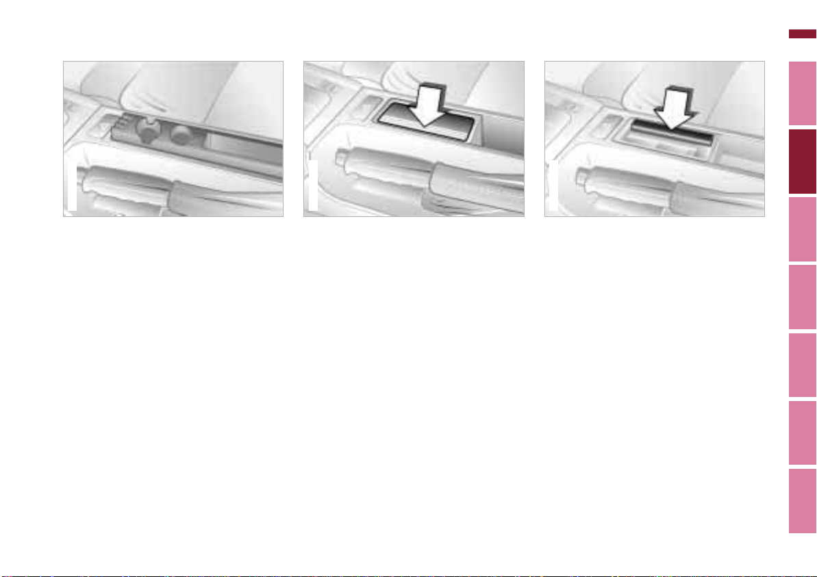
Beverage holder* Ashtray*
367de308
Online Edition for Part No. 01 41 0 155 690 - © 09/00 BMW AG
89n
367us708
The beverage holder is located in the
center console next to the parking
brake.
You will find a coin box in front of the
beverage holders.
367de038
To open
Press down on the left of the lid (arrow).
To extinguish a cigarette, tap off the
ash and gently press the tip into the
funnel.
To empty
Open the lid and press down (arrow):
The ashtray insert pops up and can be
removed.
Index Data Technology Repairs Car care Controls Overview
Page 90
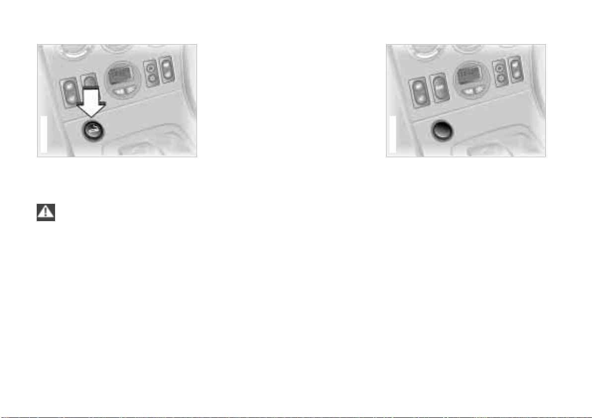
90n
367de733
Online Edition for Part No. 01 41 0 155 690 - © 09/00 BMW AG
Cigarette lighter*
367de734
Cigarette lighter socket
This socket can be used for connecting
a flashlight, car vacuum cleaner, or
other appliances up to approx.
200 watts at 12 volts. Do not damage
the socket by inserting plugs of a
different shape or size.
Press in. The lighter can be removed as
soon as it pops up.
Hold or touch the hot cigarette
lighter by the knob only. Holding
or touching it in other areas could result
in burns.
The cigarette lighter remains operational when the ignition key has been
removed. For this reason, children
should never be left in the vehicle unattended.<
Non-smoker's equipment
package
On vehicles with the non-smoker's
equipment package, the socket is
concealed by a cover.
For access to the socket: lift the cover
off.
*
Page 91
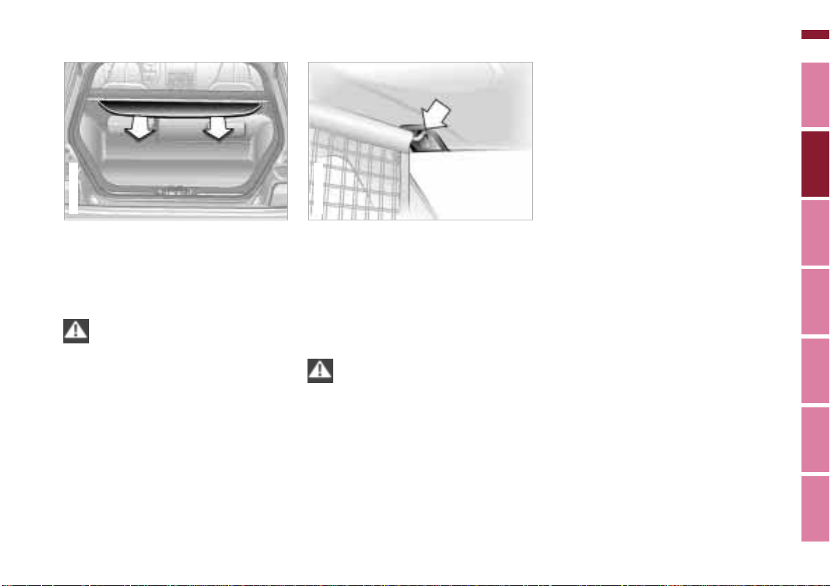
Roll-up cover Partition net*
Online Edition for Part No. 01 41 0 155 690 - © 09/00 BMW AG
91n
367de628
Z3 coupe
Pull out the roll-up cover and hook it
into the holders at the rear.
The roll-up cover can carry light items
such as articles of clothing.
Do not place heavy or hard
objects on the roll-up cover.
These objects could endanger vehicle
occupants during heavy brake applications and evasive action or in a crash.
Do not allow the roll-up cover to snap
back when it is retracted. This could
damage it.<
392de163
Z3 coupe
Pull out the partition net on the strap
and grip the bar firmly with the other
hand. Then grasp the bar on both sides,
pull it up and position it into the
holders. This process will work out best
if you do it from inside the passenger
compartment.
Do not allow the partition net to
snap back when it is retracted. If
this is done, there is a risk of personal
injury, and the partition net could be
damaged.<
Index Data Technology Repairs Car care Controls Overview
Page 92
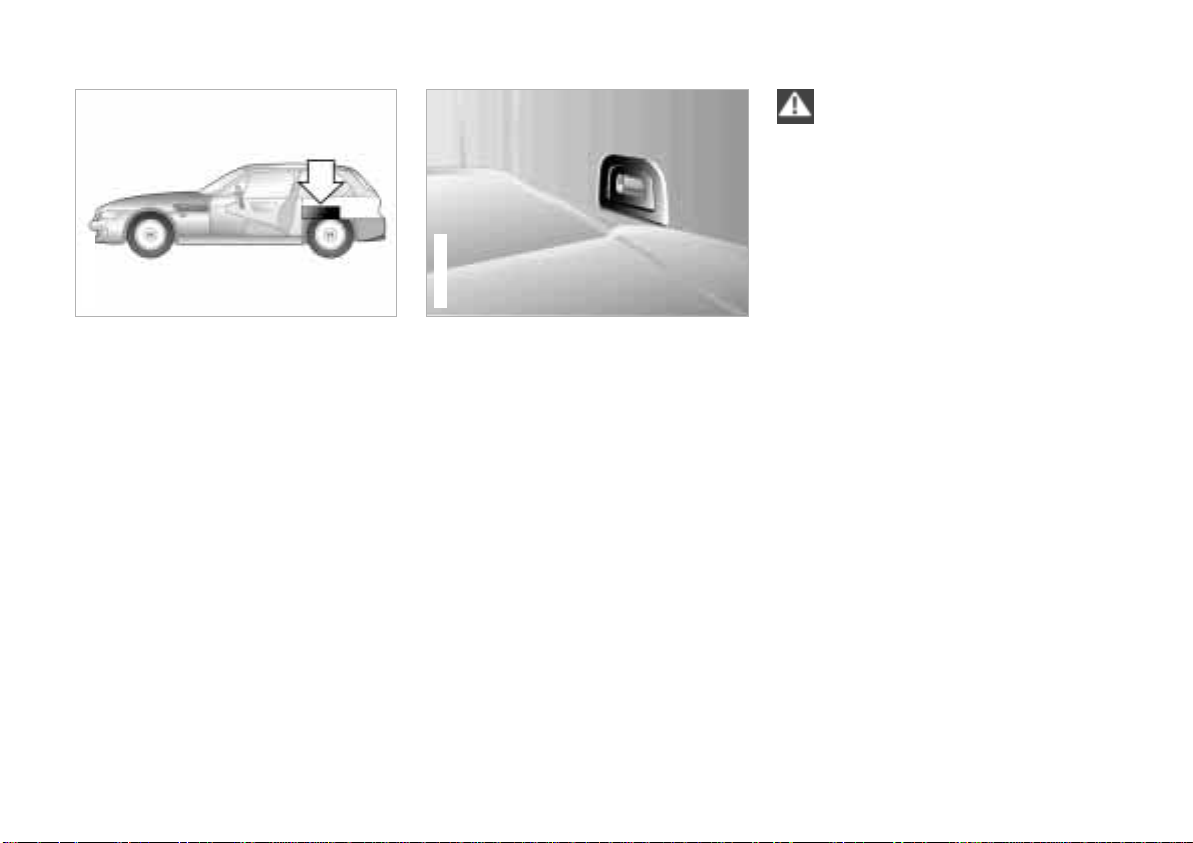
92n
Online Edition for Part No. 01 41 0 155 690 - © 09/00 BMW AG
Cargo loading
367de702
Z3 coupe
Stowing cargo
If you are transporting cargo in your
coupe:
> Load heavy cargo as far forward as
possible – directly behind the
luggage compartment partition – and
as low as possible.
> Cover sharp edges and corners.
> Do not pile objects higher than the
top edge of the backrest.
> Pull the partition net
page 91). Be sure that no items are
able to penetrate the partition net.
* out (refer to
367de627
Z3 coupe
Securing the load
For securing suitcases, you can obtain
load-securing devices
center. The lashing eyes located in the
luggage compartment serve for
mounting these load-securing devices.
Comply with the information enclosed
with the load-securing devices.
* from your BMW
Always position and secure the
load correctly. If you do not, it can
endanger the passengers during
braking or evasive maneuvers, for
example.
Do not exceed the permissible gross
weight and the permissible axle loads
(refer to page 172). If you do so, the
operating safety of the vehicle is no
longer ensured, and you are in violation
of the law.
Do not carry hard or heavy objects
unsecured in the passenger compartment. If you do so, they may be
projected through the air during braking
and evasive maneuvers, for example,
thus endangering vehicle occupants.<
Page 93

Roof-mounted luggage rack
Online Edition for Part No. 01 41 0 155 690 - © 09/00 BMW AG
93n
A special luggage system is available
for your coupe as an optional accessory. Please comply with the precautions included with the installation
instructions.
Because roof racks raise the center of
gravity of the vehicle when loaded, they
exercise a major effect on its handling
and steering response.
You should therefore always remember
not to exceed the approved roof load
capacity, the approved gross vehicle
weight or the axle weights when loading
the rack. You will find the specifications
for this under "Technical Data" on
page 172.
Make sure that the load is not too large
in size, and distribute it evenly. Always
load the heaviest pieces first (on the
bottom). Be sure that adequate clearance is maintained for raising the
sunroof, and that objects do not project
into the opening path of the luggage
compartment lid.
Lash the roof luggage down correctly
and securely to prevent it from shifting
or being lost during driving – this would
endanger following traffic.
Drive smoothly and avoid sudden
acceleration or braking. Do not corner
at high speeds.
The roof load increases the aerodynamic resistance. Increased fuel
consumption and additional stresses on
the vehicle's body result from this.
Index Data Technology Repairs Car care Controls Overview
Page 94
94n
Online Edition for Part No. 01 41 0 155 690 - © 09/00 BMW AG
Page 95

95n
Online Edition for Part No. 01 41 0 155 690 - © 09/00 BMW AG
Special operating instructions:
Break-in procedure 96
Driving notes 97
Catalytic converter 98
Antilock Brake System (ABS) 99
Disc brakes 101
Brake system 102
Winter operation 103
Power steering 104
Cellular phone 105
Radio reception 105
Hardtop – roadster 106
Wheels and tires:
Notes on inflation pressure 108
Tire condition 108
Tire replacement 109
Tire rotation 111
Wheel and tire
combinations 112
Special features of winter
tires 113
Snow chains 113
Approved wheel and tire
specifications 114
In the engine compartment:
Hood 116
Engine compartment 118
Fluids for the washer
systems 120
Washer nozzles 120
Engine oil 121
Coolant 123
Brake fluid 124
Vehicle Identification 125
Care and maintenance:
The BMW Maintenance
System 126
Caring for your vehicle 128
Airbags 134
Storing your vehicle 135
Laws and regulations:
Technical modifications 136
California Proposition
65 Warning 136
OBD connector 137
Overview
Controls and features
Operation, care
and maintenance
Owner service procedures
Advanced technology
Technical data
Index
Index Data Technology Repairs Car care Controls Overview
Car care
Page 96

96n
Online Edition for Part No. 01 41 0 155 690 - © 09/00 BMW AG
Break-in procedure
To ensure that your vehicle provides
maximum economy throughout a long
service life, we request that you
observe the following:
Engine and differential
Up to 1,200 miles (2,000 km):
Drive with varying engine and road
speeds, but do not exceed 4,500 RPM
or 100 mph (150 km/h).
Comply with local and state maximum
speed limits.
Refrain from using full throttle and avoid
pressing the accelerator beyond the
"Kickdown" point.
After you have driven 1,200 miles
(2,000 km), you can gradually increase
the engine and road speeds.
You should also comply with these
break-in procedures if the engine or
differential is replaced later in the
course of the vehicle's service life.
Tires
Due to technical factors associated with
their manufacture, tires do not achieve
their full traction potential until an initial
break-in period has elapsed. You should
therefore drive with extra caution during
the initial 200 miles (300 km).
Comply with local and state maximum
speed limits.
When the vehicle is operated on
wet or slushy roads, a wedge of
water may form between the tire and
the road surface. This phenomenon is
referred to as aquaplaning or hydroplaning, and can lead to partial or
complete loss of traction, vehicle
control and braking effectiveness.
Reduce your speed on wet roads.<
Brake system
Approximately 300 miles (500 km) must
elapse before the brake pads and discs
achieve the optimal surface and wear
pattern.
To break in the separate parking brake
drums, apply the parking brake lightly
when coasting to a standstill (at a traffic
signal, for instance), provided that
traffic conditions allow you to do so.
To avoid corrosion, repeat this procedure from time to time.
The brake lamps do not light up
when the parking brake is applied.
Vacuum for the brake system booster
on your BMW is available only when the
engine is running. When you move the
vehicle with the engine off – for instance
by towing – substantially higher levels
of pedal force will be required to brake
the vehicle.<
Clutch
The clutch will reach optimal function
after approx. 300 miles (500 km). Shift
gears carefully during the break-in
period.
,
Page 97

Driving notes
Online Edition for Part No. 01 41 0 155 690 - © 09/00 BMW AG
97n
Brakes:
Do not drive with your foot resting
on the brake pedal. Even light but
consistent pedal pressure can lead to
high temperatures, brake wear and
possibly even brake failure.
Aquaplaning:
When driving on wet or slushy roads,
reduce vehicle speed. If you do not, a
wedge of water may form between the
tires and the road surface. This
phenomenon is referred to as aquaplaning or hydroplaning. It is characterized by a partial or complete loss of
contact between the tires and the road
surface. The ultimate results are loss of
steering and braking control.
Driving through water:
When there is water on the roads, do
not drive in it if it is deeper than 1 ft
(30 cm). If the water is at that depth,
drive only at walking speed, otherwise
the vehicle can sustain damage to the
engine, the electrical systems and the
transmission.
Clothes hook (coupe):
Hang items of clothing on the hooks in
such a manner that they do not obstruct
the driver's vision. Do not hang heavy
objects on the hooks. If you do so, they
could cause personal injury during
braking and evasive maneuvers or in
a crash, for example.<
Index Data Technology Repairs Car care Controls Overview
Page 98

98n
Online Edition for Part No. 01 41 0 155 690 - © 09/00 BMW AG
Catalytic converter
The catalytic converter reduces harmful
exhaust emissions.
It is designed for use with unleaded fuel
only.
Even minute quantities of lead would be
enough to permanently damage both
the catalytic converter and the system's
oxygen sensor.
To ensure efficient, trouble-free engine
operation and avoid potential damage:
> Be sure to comply with the scheduled
maintenance requirements.
> Fill the fuel tank well before it is
empty.
> If the engine runs roughly, shut it off
as soon as possible.
> Tow-start the vehicle only when the
engine is cold. Tow-starting when the
engine is warm could cause unburned
fuel to ignite in the catalytic converter,
resulting in significant damage. It is
better to start the vehicle with an
outside starting aid.
> Avoid any other situations in which
the fuel would not be (completely)
burned, for instance:
Frequent or consecutive extended
starting attempts or repeated starting
attempts when the engine fails to
start. (Shutting down and restarting
an engine which is running properly
does not present a problem.)
Never let the engine run with any of
the spark plug cables disconnected.
Be sure to comply with the
instructions above to prevent
unburned fuel from reaching the catalytic converter. This could cause overheating, leading to serious damage of
the catalytic converter.
Extreme temperatures occur at the
catalytic converter on this and every
catalyst-equipped vehicle. Heat shields
are installed adjacent to some sections
of the exhaust system. Never remove
these shields; do not apply undercoating to their surfaces.
When driving, standing while the engine
is idling, or when parking, be careful to
avoid contact between the hot exhaust
system and easily-flammable materials
(hay, dry grass, leaves, etc.). Such
contact could cause a fire, resulting in
personal injuries and property
damage.<
Page 99

Antilock Brake System (ABS)
Online Edition for Part No. 01 41 0 155 690 - © 09/00 BMW AG
99n
The concept
ABS increases active safety by
preventing the wheels from locking
when braking. The reason: locked
wheels are dangerous. When the front
wheels slide, the driver loses steering
control over the vehicle. Traction loss at
the rear wheels can cause the rear end
to break into an uncontrolled skid.
The system can achieve the shortest
braking distances possible under most
conditions (on straight-aways and in
curves, on asphalt, ice, wet road
surfaces, etc.).
ABS is designed to meet two essential
requirements during every brake application:
> To help provide vehicle stability.
> Assured ability to steer and maneuver
on the various road surfaces (asphalt,
concrete, dirt, wet conditions, snow,
ice).
Braking with ABS
The system is operative once the
vehicle exceeds a speed of approx.
6 mph (10 km/h). It is inactivated once
again below approx. 4 mph (6 km/h).
Therefore, the wheels could theoretically tend to lock in the final phase of a
braking action, but this is insignificant in
actual practice.
If you are in a situation which requires
full braking, you will exploit the full
benefits of the ABS system if you apply
maximum brake pressure ("panic stop").
Since the vehicle maintains steering
responsiveness, you can avoid possible
obstacles with a minimum of steering
effort, despite the full brake application.
The ABS closed-loop control circuit
cycles in fractions of a second. The
pulsation at the brake pedal, together
with sounds generated by the hydraulic
control system, indicate to you that the
vehicle is approaching its maximum
braking range. It is a reminder to you
that you must adapt the vehicle's road
speed to existing road conditions.
On road surfaces that have a loose
surface layer on a firm base with good
traction (on gravel, deep sand or snow,
for example), braking distances may be
longer than with locked wheels. This
also applies for driving with snow
chains. However, ABS continues to
provide enhanced vehicle stability and
steering response under these conditions.
Index Data Technology Repairs Car care Controls Overview
Page 100
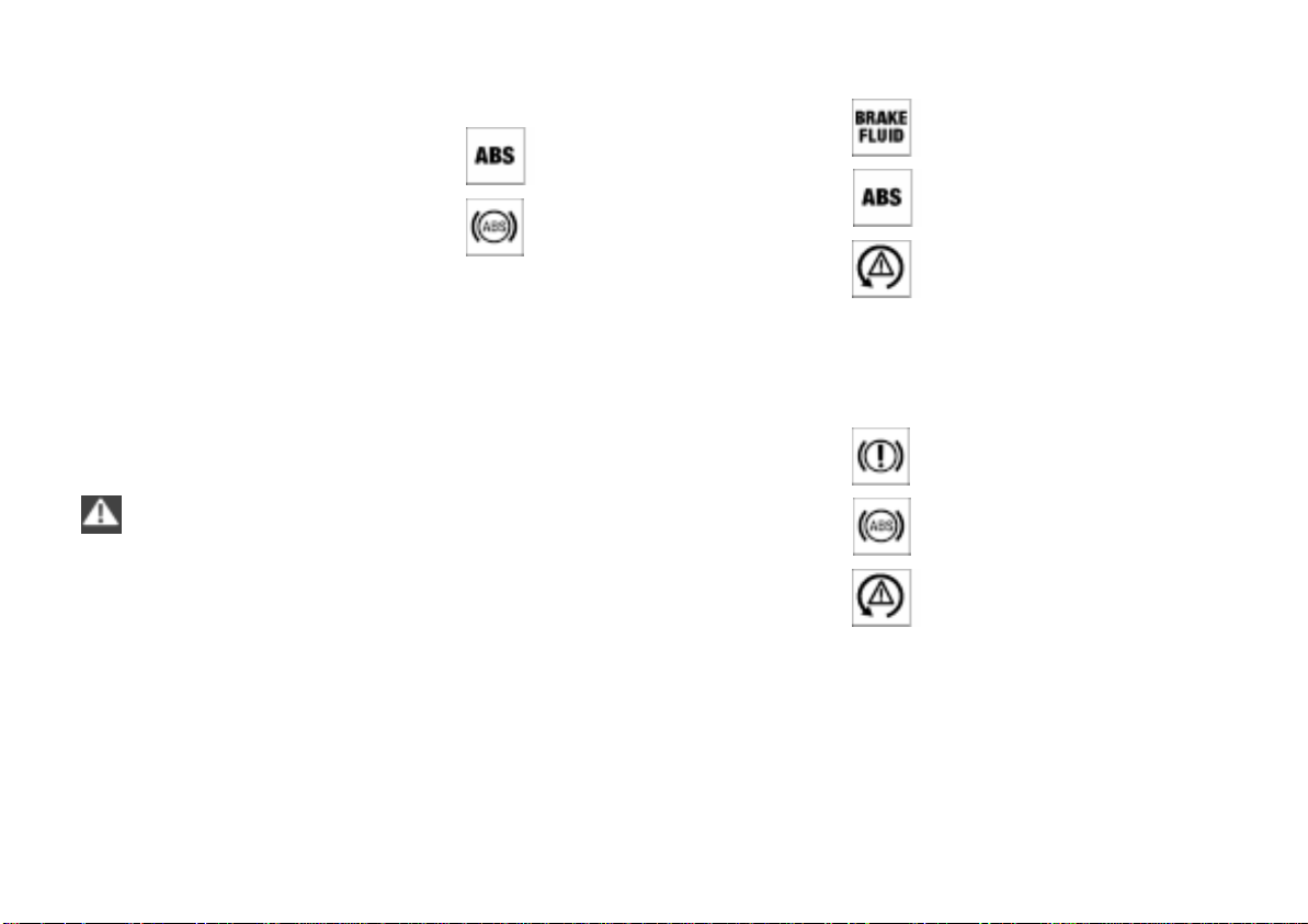
100n
Online Edition for Part No. 01 41 0 155 690 - © 09/00 BMW AG
Antilock Brake System (ABS)
Information for your safety
Not even ABS can suspend the laws
of physics. ABS alone cannot prevent
accidents if the brakes are applied
without an adequate, safe distance
between vehicles or if the speed limit
has been exceeded. Nor can it prevent
the hazards of aquaplaning. Responsibility for these types of situations
remains in the hands (and at the feet) of
the driver. You should never allow the
added safety of ABS to lull you into a
false sense of security, or mislead you
into taking increased risks that could
affect your own safety and that of
others.
Do not make any modifications to
the ABS system.
Service procedures on ABS are to be
performed by authorized technicians
only.<
Antilock Brake System (ABS)/
Cornering Brake Control (CBC)
CBC is an advanced engineering
design of the ABS. When braking while
cornering at high speed or braking
during high lateral acceleration, or
when braking during a lane change,
vehicle stability is improved and
steering response is enhanced.
In the event of a fault
The ABS warning lamp comes
on, refer to page 21. The brake
system then reverts to conventional operation as on vehicles
without ABS. However, have the
brake system checked by your
BMW center as soon as possible. To
prevent undetected defects and cumulative faults from adversely affecting the
brake system, refer any problems to
your BMW center at the earliest opportunity.
The red warning lamp for the
brake hydraulic system comes
on together with the yellow indicator lamps for ABS, ASC+T/
and ADB/DBC (refer to
DSC
page 21), the entire ABS, CBC,
ASC+T/DSC and ADB/DBC
control system has failed.
Continue to drive cautiously and
defensively. Avoid full brake applications because the vehicle could
become unstable and go out of control.
Have the system checked by your BMW
center as soon as possible.
Warning lamps for Canadian
models.
 Loading...