

Page 1

T.O. BMS1F-16CM-1 BMS 4.34 Change 2.00
BMS 4.34 Dash 1
© Red Dog 2012-2019 Page: 1
T.O. BMS1F-16CM-1
FLIGHT MANUAL
Combatsimchecklist series
F-16C/D BMS 4.34
Block 50 and 52
23 March 2019
CHANGE 2.00
Page 2

T.O. BMS1F-16CM-1 BMS 4.34 Change 2.00
BMS 4.34 Dash 1
© Red Dog 2012-2019 Page: 2
LIST OF EFFECTIVE CHANGES
This document will be updated in accordance with BMS releases. You should consider the Dash 1 as
a work in progress. It was started during BMS beta testing and updated to reflect the release version
changes. It may already be outdated from the current beta BMS version but will be updated shortly
after each release.
Change 2: (4.34)
(V2.00) published Feb 06th, 2019.
• 4.34 Dash1 update with many changes all around.
Change 1: (4.33)
(V1.06) published March 26th, 2016.
• Updated for 4.33 Update 1.
• Added MFL analysis
(V1.05) published Sept 5th, 2015.
• Added ILS section from BMS 4.32 Manual with relevant changes.
• Added section IV Flight Characteristics.
(V1.04) published August 9th, 2015.
• Merged AAR section from BMS Manual.
(V1.03) published July 13th, 2015.
• Proof read and 4.33RC changes.
• Updated pictures to reflect latest changes.
(V1.02) published March 31st, 2015.
• Proof read and 4.33RC changes.
(V1.01) published March 10th, 2015.
• First 4.33 Dash1 update (all systems).
• Added TFR & FLIR MFD pages.
• Added Pilot Fault List Analysis.
• Added 4.33 Callbacks.
Change 0: (4.32)
(V1.0) published March 28th, 2012.
• First released version.
(V0.8 draft) published March 24th, 2012.
• Proof read corrections.
(V0.7 draft) published January 11th, 2012.
• Changed structure of chapters.
• Added Landing chapter in Normal Procedures.
Page 3

T.O. BMS1F-16CM-1 BMS 4.34 Change 2.00
BMS 4.34 Dash 1
© Red Dog 2012-2019 Page: 3
• Changed MARK POINTS section in UFC for OFLY, HUD, FCR & TGP mark.
• Added HUD Mark section in HUD chapter.
• Added training for flameout situation.
(V0.6 draft) published Dec 30th, 2011.
• Moved hotpit refuel & AA refuel to section II - normal procedure.
• Added Section III: Abnormal & Emergency procedures.
• Added Warning Light & Caution Light Analysis.
• Added Ground, Takeoff, In-flight & Landing emergencies.
• Adapted changes for 4.32 Update 1 change log.
(V0.5 draft) published August 31st, 2011.
• Various corrections from proof readers.
• Added Section2 – Normal Procedures.
(V0.4 draft) published August 29th, 2011.
• Added UFC, MFD, Engine, Fuel, ECS, Hydraulic, FLCS, EPU, Gear, Autopilot chapter
• Document formatting.
• Added BMS 4.32 callbacks.
• Added HUD chapter.
• Added Bibliography.
(V0.3 draft) published July 31st, 2011.
COPYRIGHT STATEMENTS
Falcon BMS is a community mod developed and published by Benchmark Sims for use with licensed copies of
Falcon 4.0. Unauthorized rental, sales, arcade use, charging for use, or any commercial use of this mod or part
thereof is prohibited.
This mod is for non-commercial use only.
This mod was created by Benchmark Sims with the permission of Billion Soft (Hong Kong) Limited.
This mod and all included content are in no way affiliated with Billion Soft (Hong Kong) Limited
or Retroism.
© 2003-2019 Benchmark Sims. All rights reserved.
Falcon is a registered trademark of Billion Soft (Hong Kong) Limited.
Falcon Collection and Falcon 4.0 are published by Retroism.
Retroism, the Retroism logo and the Billion Soft logo are trademarks or registered trademarks.
© 2019 Billion Soft (Hong Kong) Limited. All rights reserved.
The T.O. BMS1F-16CM-1 manual is published by Olivier “Red Dog” Beaumont.
Unauthorized rental, sales, charging for use, or any commercial use of this manual or part thereof is prohibited.
This manual is for non-commercial use only.
No reproduction of this manual or part of this manual is allowed without the written permission of the author.
© 2012-2019. All rights reserved.
Page 4

T.O. BMS1F-16CM-1 BMS 4.34 Change 2.00
BMS 4.34 Dash 1
© Red Dog 2012-2019 Page: 4
TABLE OF CONTENTS
LIST OF EFFECTIVE CHANGES ........................................................................................................ 2
Change 2: (4.34) ....................................................................................................................................... 2
(V2.00) published Feb 06th, 2019. ............................................................................................................ 2
Change 1: (4.33) ....................................................................................................................................... 2
(V1.06) published March 26th, 2016. ........................................................................................................ 2
(V1.05) published Sept 5th, 2015. ............................................................................................................. 2
(V1.04) published August 9th, 2015. ......................................................................................................... 2
(V1.03) published July 13th, 2015. ............................................................................................................ 2
(V1.02) published March 31st, 2015. ......................................................................................................... 2
(V1.01) published March 10th, 2015. ........................................................................................................ 2
Change 0: (4.32) ....................................................................................................................................... 2
(V1.0) published March 28th, 2012. .......................................................................................................... 2
(V0.8 draft) published March 24th, 2012. .................................................................................................. 2
(V0.7 draft) published January 11th, 2012. ............................................................................................... 2
(V0.6 draft) published Dec 30th, 2011. ....................................................................................................... 3
(V0.5 draft) published August 31st, 2011. .................................................................................................. 3
(V0.4 draft) published August 29th, 2011. .................................................................................................. 3
(V0.3 draft) published July 31st, 2011. ....................................................................................................... 3
COPYRIGHT STATEMENTS .............................................................................................................. 3
TABLE OF CONTENTS ...................................................................................................................... 4
SECTION I DESCRIPTION & OPERATION ..................................... 11
1.1 THE AIRCRAFT .......................................................................................................................... 12
1.2 COCKPIT ARRANGEMENT ........................................................................................................ 13
1.2.1. LEFT CONSOLE ................................................................................................................ 15
1.2.1.1 TEST panel ................................................................................................................................. 16
1.2.1.2 FLT CONTROL Panel (FLCP) ..................................................................................................... 17
1.2.1.3 MANUAL TRIM panel .................................................................................................................. 18
1.2.1.4 FUEL panel ................................................................................................................................. 18
1.2.1.5 IFF panel ..................................................................................................................................... 19
1.2.1.6 EXT LIGHTING panel .................................................................................................................. 21
1.2.1.7 AVTR panel ................................................................................................................................. 22
1.2.1.8 ECM panel................................................................................................................................... 22
1.2.1.9 ELEC panel ................................................................................................................................. 23
1.2.1.10 EPU panel ................................................................................................................................. 24
1.2.1.11 AUDIO 2 panel .......................................................................................................................... 25
1.2.1.12 AUDIO 1 panel .......................................................................................................................... 25
1.2.1.13 ENG & JET START panel ......................................................................................................... 26
1.2.1.14 Backup UHF panel .................................................................................................................... 27
1.2.1.15 MANUAL PITCH override panel ................................................................................................ 28
1.2.1.16 Throttle grip and left side wall .................................................................................................... 28
1.2.2. LEFT AUXILIARY CONSOLE ............................................................................................. 31
1.2.2.1 ALT GEAR HANDLE ................................................................................................................... 32
1.2.2.2 TWA panel................................................................................................................................... 32
1.2.2.3 HMCS panel ................................................................................................................................ 32
1.2.2.4 CMDS panel ................................................................................................................................ 33
1.2.2.5 Speedbrake indicator .................................................................................................................. 34
1.2.2.6 Gear panel................................................................................................................................... 35
1.2.3. CENTRE CONSOLE .......................................................................................................... 37
1.2.3.1 MISC panel .................................................................................................................................. 38
1.2.3.2 Left EYEBROW ........................................................................................................................... 39
1.2.3.3 Left MFD & Right MFD ................................................................................................................ 40
1.2.3.4 TWP panel................................................................................................................................... 41
1.2.3.5 ALR-56 RWR ............................................................................................................................... 42
1.2.3.6 Left INDEXER ............................................................................................................................. 42
1.2.3.7 HUD ............................................................................................................................................ 42
1.2.3.8 ICP & DED .................................................................................................................................. 43
1.2.3.9 MACHMETER ............................................................................................................................. 43
1.2.3.10 ALTIMETER .............................................................................................................................. 44
Page 5

T.O. BMS1F-16CM-1 BMS 4.34 Change 2.00
BMS 4.34 Dash 1
© Red Dog 2012-2019 Page: 5
1.2.3.11 AOA ........................................................................................................................................... 44
1.2.3.12 ADI ............................................................................................................................................ 44
1.2.3.13 VVI ............................................................................................................................................ 45
1.2.3.14 INSTRUMENT MODE panel ..................................................................................................... 45
1.2.3.15 EHSI .......................................................................................................................................... 45
1.2.3.16 FUEL QTY SEL panel ............................................................................................................... 46
1.2.3.17 MARKER BEACON ................................................................................................................... 47
1.2.3.18 FUEL FLOW indicator ............................................................................................................... 47
1.2.3.19 Backup ADI ............................................................................................................................... 47
1.2.3.20 Right INDEXER ......................................................................................................................... 47
1.2.3.21 Right EYEBROW ....................................................................................................................... 48
1.2.3.22 Right INSTRUMENT stack ........................................................................................................ 49
1.2.4. RIGHT AUXILIARY CONSOLE .......................................................................................... 50
1.2.4.1 Compass ..................................................................................................................................... 51
1.2.4.2 FUEL Quantity indicator .............................................................................................................. 51
1.2.4.3 Pilot Fault List Display ................................ ................................................................ ................. 51
1.2.4.4 HYD PRESS system A & B gauges ............................................................................................ 51
1.2.4.5 CAUTION light panel ................................................................................................................... 52
1.2.4.6 LIQUID OXYGEN gauge ............................................................................................................. 52
1.2.4.7 EPU FUEL gauge ........................................................................................................................ 52
1.2.4.8 CABIN PRESS ALT gauge .......................................................................................................... 52
1.2.4.9 Clock ........................................................................................................................................... 52
1.2.5. RIGHT CONSOLE .............................................................................................................. 53
1.2.5.1 SNSR PWR Panel ....................................................................................................................... 54
1.2.5.2 SIDESTICK CONTROLLER (SSC) ............................................................................................. 55
1.2.5.3 HUD panel ................................................................................................................................... 57
1.2.5.4 NUCLEAR panel ......................................................................................................................... 58
1.2.5.5 ZEROIZE panel ........................................................................................................................... 58
1.2.5.6 VMS panel ................................................................................................................................... 58
1.2.5.7 Internal LIGHTING panel ............................................................................................................. 59
1.2.5.8 AIR COND panel ......................................................................................................................... 59
1.2.5.9 KY 58 panel ................................................................................................................................. 60
1.2.5.10 ANTI ICE panel ......................................................................................................................... 60
1.2.5.11 AVIONICS POWER panel ......................................................................................................... 60
1.2.5.12 OXYGEN REGULATOR panel .................................................................................................. 61
1.2.5.13 DTU panel ................................................................................................................................. 61
1.2.6. MISCELLANEOUS ............................................................................................................. 62
1.2.6.1 NVG ............................................................................................................................................ 62
1.2.6.2 HELMET VISOR .......................................................................................................................... 63
1.2.6.3 PILOT MODEL ............................................................................................................................ 63
1.3 UP FRONT CONTROLS ............................................................................................................. 64
1.3.1. Data Command Switch (DCS) & scratchpad ................................................................................. 66
1.3.2. ENTR and RCL button .................................................................................................................. 66
1.3.3. DED scratchpad ............................................................................................................................ 66
1.3.4. CNI page ....................................................................................................................................... 66
1.3.5. T-ILS page (1) ............................................................................................................................... 67
1.3.6. A-LOW page (2) ............................................................................................................................ 67
1.3.7. STPT page (4) ............................................................................................................................... 68
1.3.8. CRUS page (5) .............................................................................................................................. 68
1.3.9. TIME page (6) ............................................................................................................................... 69
1.3.10. MARK page (7) ................................ ................................................................ ............................ 70
1.3.11. FIX page (8) ................................................................................................................................ 71
1.3.12. A-CAL page (9) ........................................................................................................................... 71
1.3.13. COM1 page ................................................................................................................................. 71
1.3.14. COM2 page ................................................................................................................................. 71
1.3.15. IFF page ...................................................................................................................................... 72
1.3.16. LIST page .................................................................................................................................... 74
1.3.17. DRIFT C/O switch ....................................................................................................................... 80
1.3.18. The ICP Thumbwheels ................................................................................................................ 80
1.4 MULTI FUNCTION DISPLAYS .................................................................................................... 81
1.4.1. Menu page .................................................................................................................................... 81
1.4.2. Sensor of Interest (SOI) ................................................................................................................ 82
1.4.3. HSD page ...................................................................................................................................... 83
1.4.4. TEST page .................................................................................................................................... 86
Page 6

T.O. BMS1F-16CM-1 BMS 4.34 Change 2.00
BMS 4.34 Dash 1
© Red Dog 2012-2019 Page: 6
1.4.5. SMS page...................................................................................................................................... 87
1.4.6. TFR page ...................................................................................................................................... 91
1.4.7. DTE page ...................................................................................................................................... 92
1.4.8. FLCS page .................................................................................................................................... 92
1.4.9. Forward Looking Infrared (FLIR) page .......................................................................................... 93
1.4.10. WPN page ................................................................................................................................... 94
1.4.11. TGP page .................................................................................................................................... 94
1.4.12. HAD page .................................................................................................................................... 95
1.4.13. BLANK page ................................................................................................................................ 95
1.4.14. RCCE page ................................................................................................................................. 95
1.4.15. RESET MENU page .................................................................................................................... 96
1.4.16. FCR page .................................................................................................................................... 96
1.4.17. TACAN page ............................................................................................................................. 103
1.4.18. Setting the MFDs according to Master Mode (DTC) .................................................................. 104
1.5. THE HEAD UP DISPLAY (HUD)............................................................................................... 106
1.5.1. HUD SETTINGS .......................................................................................................................... 106
1.5.2. HUD in NAV mode ...................................................................................................................... 110
1.5.3. HUD with GEAR DOWN .............................................................................................................. 111
1.5.4. HUD in AIR to AIR mode ............................................................................................................. 112
1.5.5. HUD in AIR to GROUND ............................................................................................................. 113
1.5.6. HUD as SENSOR OF INTEREST (SOI) ..................................................................................... 113
1.5.7. HUD WARNING .......................................................................................................................... 114
1.5.8. HUD CARA .................................................................................................................................. 114
1.5.9. DEPRESSIBLE RETICLE SWITCH ............................................................................................ 115
1.5.10. HUD MARK ............................................................................................................................... 116
1.6 THE ENGINE ............................................................................................................................. 117
1.6.1. Primary (PRI) and Secondary (SEC) engine control ................................................................... 117
1.6.2. Exhaust nozzle ............................................................................................................................ 117
1.6.3. Engine Oil system ....................................................................................................................... 117
1.6.4. Engine Anti-Ice system ................................................................................................................ 117
1.6.5. Jet Fuel Starter (JFS) .................................................................................................................. 117
1.6.6. Engine Warning & Caution lights ................................................................................................. 118
1.6.7. Engine instruments ...................................................................................................................... 118
1.6.8. Throttle ........................................................................................................................................ 118
1.6.9. Ground operations ....................................................................................................................... 119
1.7 FUEL SYSTEM .......................................................................................................................... 120
1.7.1. Fuel SHUTOFF valve. ................................................................................................ ................. 122
1.7.2. Fuel pumps .................................................................................................................................. 122
1.7.3. Fuel pressurisation ...................................................................................................................... 123
1.7.4. Fuel quantity indicating system ................................................................................................... 124
1.7.5. External fuel transfer switch ........................................................................................................ 125
1.7.6. Fuel checks ................................................................................................................................. 125
1.7.7. Fuel imbalance ............................................................................................................................ 126
1.7.8. Analysis of caution lights & HUD messages relevant to the fuel system ..................................... 127
1.7.9. Managing Fuel: Joker & Bingo .................................................................................................... 129
1.8 ENVIRONMENTAL CONTROL SYSTEM (ECS) ....................................................................... 131
1.8.1. ECS PFL/Caution/Warning lights ................................................................................................ 131
1.9 ELECTRICAL SYSTEM ............................................................................................................. 132
1.9.1 Electrical System Normal Operation: ............................................................................................ 132
1.9.2. Electrical caution/warning lights .................................................................................................. 133
1.10 HYDRAULIC SYSTEM ............................................................................................................ 135
1.11 EMERGENCY POWER UNIT (EPU) ....................................................................................... 135
1.12 FLIGHT CONTROL SYSTEM (FLCS) ..................................................................................... 136
1.12.1 CRUISE GAINS ............................................................................................................... 136
1.12.1.1 Pitch FLCS .............................................................................................................................. 136
1.12.1.2. Roll FLCS ............................................................................................................................... 137
Page 7

T.O. BMS1F-16CM-1 BMS 4.34 Change 2.00
BMS 4.34 Dash 1
© Red Dog 2012-2019 Page: 7
1.12.1.3. Yaw FLCS .............................................................................................................................. 137
1.12.2. TAKEOFF & LANDING gains ......................................................................................... 137
1.12.2.1 Pitch FLCS .............................................................................................................................. 137
1.12.2.2. Roll FLCS ............................................................................................................................... 138
1.12.3. STANDBY gains ............................................................................................................. 138
1.12.4. Gun compensation .......................................................................................................... 138
1.12.5. Leading Edge Flaps (LEF) and Trailing Edge Flaps (TEF) ............................................ 138
1.12.6. Digital Backup (DBU) ...................................................................................................... 139
1.12.7. Asymmetrical loading ...................................................................................................... 139
1.12.8. FLCS BIT ........................................................................................................................ 140
1.12.9. FLCS warning/caution lights ........................................................................................... 140
1.13 LANDING GEAR & BRAKES ................................................................................................... 141
1.13.1. Nose Wheel Steering ................................................................................................................ 141
1.13.2. Wheel brakes ............................................................................................................................ 141
1.13.3. Parking Brake & Chocks ........................................................................................................... 142
1.13.4. Speed Brake system ................................................................................................................. 142
1.14 AUTOPILOT OPERATION ...................................................................................................... 143
1.14.1. Altitude Hold .............................................................................................................................. 143
1.14.2. Attitude Hold (PITCH) ................................................................................................................ 143
1.14.3. Heading Select (ROLL) ............................................................................................................. 144
1.14.4. Attitude Hold (ROLL) ................................................................................................................. 144
1.14.5. Steering Select (ROLL) ............................................................................................................. 144
1.14.6. Autopilot limits ........................................................................................................................... 144
1.15 INSTRUMENT LANDING SYSTEM ........................................................................................ 145
1.16. IDENTIFICATION FRIEND OR FOE (IFF) .............................................................................. 150
1.16.1 IFF modes .................................................................................................................................. 150
1.16.2 Cockpit controls .......................................................................................................................... 151
1.16.3 IFF DTC Brief ............................................................................................................................. 151
1.16.4 How to use the IFF in flight ......................................................................................................... 153
1.16.5. IFF use in backup mode ............................................................................................................ 158
1.16.6 IFF in emergency ....................................................................................................................... 159
SECTION II NORMAL PROCEDURES ........................................... 161
2.1. RAMP START IN 3 SWEEPS .................................................................................................... 162
1st Sweep: Before starting the engine ................................................................................................... 162
2nd Sweep: Starting engine & systems .................................................................................................. 166
3rd Sweep: The final sweep ................................................................................................................... 168
2.2. REFUELLING ........................................................................................................................... 173
2.2.1 Hotpit refuelling ............................................................................................................................ 173
2.2.2 Air to Air refuelling (AAR) ............................................................................................................. 173
2.3. LANDING .................................................................................................................................. 182
SECTION III ABNORMAL & EMERGENCY PROCEDURES ......... 186
3.1. WARNING AND CAUTION LIGHT AND PILOT FAULT SYSTEM ........................................... 187
3.1.1 MASTER CAUTION light .............................................................................................................. 188
3.1.2 Caution lights................................................................................................................................ 188
3.1.3 Warning lights ............................................................................................................................... 188
3.1.4 Pilot Fault List Display (PFLD) ...................................................................................................... 189
3.1.5 Maintenance Fault List ................................................................................................................. 189
3.1.6 Voice Message System (VMS) ..................................................................................................... 189
3.2. WARNING LIGHT ANALYSIS .................................................................................................. 191
3.2.1. ENG FIRE ................................................................................................................................... 191
3.2.2. TO/LDG CONFIG ........................................................................................................................ 191
3.2.3. CANOPY ..................................................................................................................................... 191
3.2.4. FLCS ........................................................................................................................................... 191
3.2.5. HYD/OIL PRESS ......................................................................................................................... 192
3.2.6. OXY LOW.................................................................................................................................... 192
3.2.7. DBU ON ...................................................................................................................................... 192
Page 8

T.O. BMS1F-16CM-1 BMS 4.34 Change 2.00
BMS 4.34 Dash 1
© Red Dog 2012-2019 Page: 8
3.2.8. TF FAIL ....................................................................................................................................... 192
3.2.9. ENGINE ...................................................................................................................................... 193
3.2.10. GEAR HANDLE LIGHT ............................................................................................................. 193
3.2.11. HUD WARN ............................................................................................................................... 193
3.3. CAUTION LIGHT ANALYSIS ................................................................................................... 194
3.3.1. MASTER CAUTION .................................................................................................................... 194
3.3.2. CAUTION PANEL LIGHTS.......................................................................................................... 194
3.4. FAULT ANALYSIS .................................................................................................................... 197
3.4.1. Maintenance Fault List (MFL) ........................................................................................... 197
3.4.1.1. MFL management at ramp start ............................................................................................... 199
3.4.1.2. DTC fault recording .................................................................................................................. 199
3.4.2. PILOT FAULT LIST (PFL) ................................................................................................ 200
3.4.2.1. Example workflow: Ramp Start with AIR SOURCE knob out of NORM ................................... 201
3.4.2.2. Special considerations: ............................................................................................................ 202
3.4.3. Table of possible faults (PFL & MFL): .............................................................................. 203
3.5. GROUND EMERGENCIES ...................................................................................................... 207
3.5.1 HUNG START / NO START ......................................................................................................... 207
3.5.2 ENGINE START IN BATTERY ..................................................................................................... 207
3.5.3 HOT START ................................................................................................................................. 207
3.5.4 OIL PRESSURE ........................................................................................................................... 207
3.5.4 EQUIP HOT CAUTION LIGHT ..................................................................................................... 208
3.5.5 FLCS BIT FAILURE ..................................................................................................................... 208
3.5.6 HOT BRAKES .............................................................................................................................. 208
3.5.7 NWS FAILURE ............................................................................................................................. 209
3.6. TAKEOFF EMERGENCIES ..................................................................................................... 210
3.6.1 ABORT / REJECTED TAKEOFF ................................................................ .................................. 210
3.6.2 LG FAILS TO RETRACT .............................................................................................................. 210
3.6.3 BLOWN TYRE ON TAKEOFF ...................................................................................................... 211
3.7. IN FLIGHT EMERGENCIES ..................................................................................................... 212
3.7.1 COCKPIT PRESSURE MALFUNCTIONS.................................................................................... 212
3.7.2 EQUIP HOT CAUTION LIGHT ..................................................................................................... 212
3.7.3 EJECTION.................................................................................................................................... 212
3.7.4 ELECTRICAL SYSTEM FAILURE ............................................................................................... 212
3.7.5 ENGINE MALFUNCTIONS .......................................................................................................... 212
3.7.6 JETTISON .................................................................................................................................... 218
3.7.7 EGI In-Flight Alignment (IFI) ......................................................................................................... 219
3.7.8 Controllability Check ..................................................................................................................... 219
3.7.9 Out of Control Recovery ............................................................................................................... 219
3.7.10 Fuel leak ..................................................................................................................................... 220
3.7.11 Oil Leak ...................................................................................................................................... 220
3.7.12 Battle Damage Checks ............................................................................................................... 220
3.8. LANDING EMERGENCIES ...................................................................................................... 221
3.8.1 LANDING WITH A BLOWN TYRE ............................................................................................... 221
3.8.2 LG EXTENSION MALFUNCTIONS .............................................................................................. 221
3.8.3 LANDING WITH GEAR UNSAFE/UP ........................................................................................... 222
3.8.4 BRAKE MALFUNCTIONS ............................................................................................................ 223
3.8.5 NOSE WHEEL STEERING MALFUNCTION ............................................................................... 223
3.8.6 TAKEOFF & LANDING IN CROSSWINDS .................................................................................. 223
SECTION IV FLIGHT CHARACTERISTICS ...................................... 226
4.1 LIMIT CYCLE OSCILLATION ........................................................................................................... 227
4.2 DESCENT WARNING ADVISORY..................................................................................................... 227
4.3 CATEGORY LOADING .................................................................................................................... 228
4.4. DEPARTURE FROM CONTROLLED FLIGHT ................................................................................ 228
4.4.1 Rudder input ................................................................................................................................. 228
4.4.2 Flight with stores .......................................................................................................................... 228
4.4.3 Asymmetric loading ...................................................................................................................... 229
4.4.4 Type of departure ......................................................................................................................... 229
Page 9

T.O. BMS1F-16CM-1 BMS 4.34 Change 2.00
BMS 4.34 Dash 1
© Red Dog 2012-2019 Page: 9
4.4.5 Deep Stalls & Recovery ............................................................................................................... 229
4.5 OPERATING LIMITS & RESTRICTIONS ............................................................................................ 231
5. BIBLIOGRAPHY .............................................................................. 233
6. ACKNOWLEDGMENT ..................................................................... 234
Page 10

T.O. BMS1F-16CM-1 BMS 4.34 Change 2.00
BMS 4.34 Dash 1
© Red Dog 2012-2019 Page: 10
INTENTIONALLY LEFT BLANK
Page 11

T.O. BMS1F-16CM-1 BMS 4.34 Change 2.00
BMS 4.34 Dash 1
© Red Dog 2012-2019 Page: 11
SECTION I
DESCRIPTION & OPERATION
Page 12

T.O. BMS1F-16CM-1 BMS 4.34 Change 2.00
BMS 4.34 Dash 1
© Red Dog 2012-2019 Page: 12
1.1 THE AIRCRAFT
In BMS you have the opportunity to fly a greater variety of F-16 blocks than ever before, many of them
with country specific avionics and skins.
In the training TEs you will transition from some of the earlier blocks to more recent models with much
more advanced avionics, some of them two-seaters.
Different variants all have their own unique setup, such as support for certain weapons, built-in ECM,
different radar, updated RWR, support for conformal fuel tanks (CFT) and so on. All these versions
have their differences so in order to keep this document simple we will concentrate primarily on one
variant: the F-16C/D block 50 with the GE-129 engine.
Aircraft weights
The Gross Weight (GW) of the BMS F-16C (including oil, pilot, two wingtip AIM-120 missiles and a full
load of 20mm ammunition is approximately 20500 lbs. With Full Internal fuel the GW is approximately
28000 lbs. The Max Take-Off weight is 42300 lbs.
Fuel Weight is 7162 lbs internally in 7 fuel tanks:
• Left wing (± 525 lbs)
• Right wing (± 525 lbs)
• Two forward fuselage F1 & F2, considered as a single F tank in BMS (± 3250 lbs)
• One aft fuselage: A (± 2810 lbs)
• And two reserve tanks: fwd reservoir and aft reservoir, each holding ± 480 lbs.
The two reserve fuselage tanks (F & A) supply fuel directly to the engine.
The D model has a smaller front fuselage (F) fuel capacity because of the second cockpit (1890 vs
3250 lbs). Fuselage fuel is therefore 4800 lbs and full internal fuel is 5900 lbs.
The F-16 can carry 3 external fuel tanks: 2 wing tanks of 370 Gallons (2516 lbs) each and a centreline
300 Gallon tank (2040 lbs) tank.
Total fuel weight with three external tanks is thus 14234 lbs (C model). We also have the capability to
load 600 Gallon non-jettisonable wing tanks, though it is rarely done.
Conformal Fuel Tanks (if fitted) are considered part of the internal wing tanks for BMS fuel gauges.
Most of your flights will be done with a full load of internal fuel and 2 x 370 Gallon wing tanks.
The F-16 has no capability to vent fuel overboard. Air to Air Refuelling is provided through an AR port
on top of the fuselage.
The F-16 doesn’t have a maximum landing weight. You can land the aircraft at any weight as long as
the runway is long enough to accommodate the longer landing roll.
Aircraft speeds
Max Undercarriage speed is 305 knots.
The F-16 does not have a true corner velocity. It has a corner plateau from 330 to 440 knots that
produces good turn rate based on available G according to altitude.
Manoeuvre speed is around 340 knots.
Page 13
T.O. BMS1F-16CM-1 BMS 4.34 Change 2.00
BMS 4.34 Dash 1
© Red Dog 2012-2019 Page: 13
1.2 COCKPIT ARRANGEMENT
Page 14

T.O. BMS1F-16CM-1 BMS 4.34 Change 2.00
BMS 4.34 Dash 1
© Red Dog 2012-2019 Page: 14
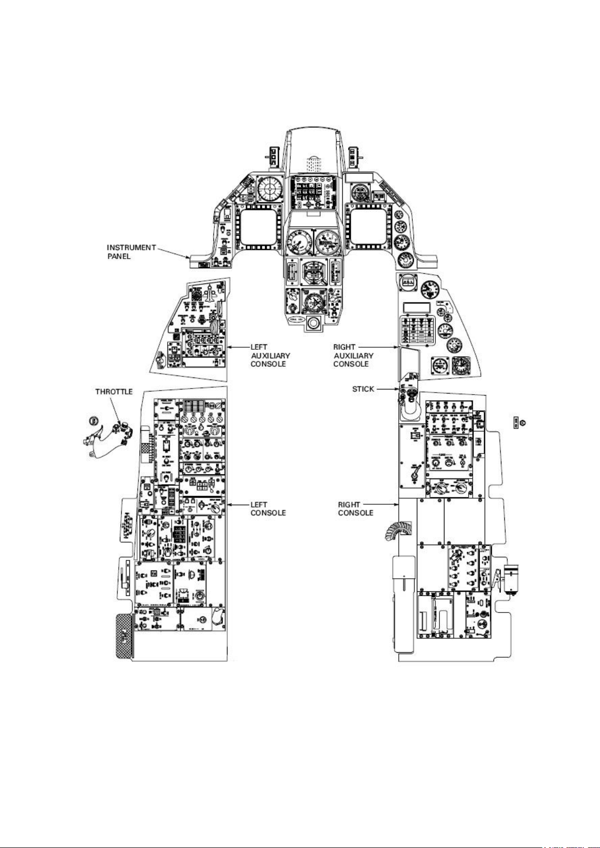
The F-16 cockpit is made up of the left console, left auxiliary console, centre panel, right auxiliary
console and right console.
The left and right console are mainly used for start-up and ground ops, the auxiliaries and centre
panels are mostly used in flight.
The heart of the onboard system is provided by the Up Front Controller (ICP & DED) and the 2 MFDs.
All primary system management can be set through these.
In BMS the 3D cockpit is now our primary interface with the sim (the 2D cockpit is a thing of the past).
View panning in the 3D cockpit is performed with Track IR (TIR) or similar tracking software, though
you can pan around manually with a POV hat on a joystick/controller if set up properly.
Each button or knob can be interfaced with the keyboard or the mouse.
When interfacing switches with the keyboard, we use specific key callbacks for that switch. They can
be toggles, full states position switches, push button press, push button release.
Callbacks are listed in the key file (\User\Config folder) where they are declared as a keystroke.
In turn these keystrokes can be programmed as HOTAS buttons, or used in full cockpit programming.
All active 3Dswitches can also be interfaced with the mouse. In this case we use the 3D button hotspot
in the 3D cockpit and the mouse buttons.
Hotspots are displayed in the 3D cockpit with a change of cursor colour. When your mouse cursor
reaches a hotspot it turns green, signalling the hotspot presence for the switch.
Usually moving the switch up is accomplished by depressing the left mouse button and moving it down
is done with the right mouse button. The same is true for push buttons; they can be depressed with
one mouse button and released with the other button.
Rotaries are usually incremented with the left mouse button and decremented with the right mouse
button.
Encoders such as the CRS and HDG knobs on the HSI can be more rapidly adjusted with the mouse
wheel. When the mouse is moved over a knob featuring that implementation the cursor will display a
rotating effect signalling that the mouse wheel can be used. This is much faster than repeatedly
clicking with the mouse button.
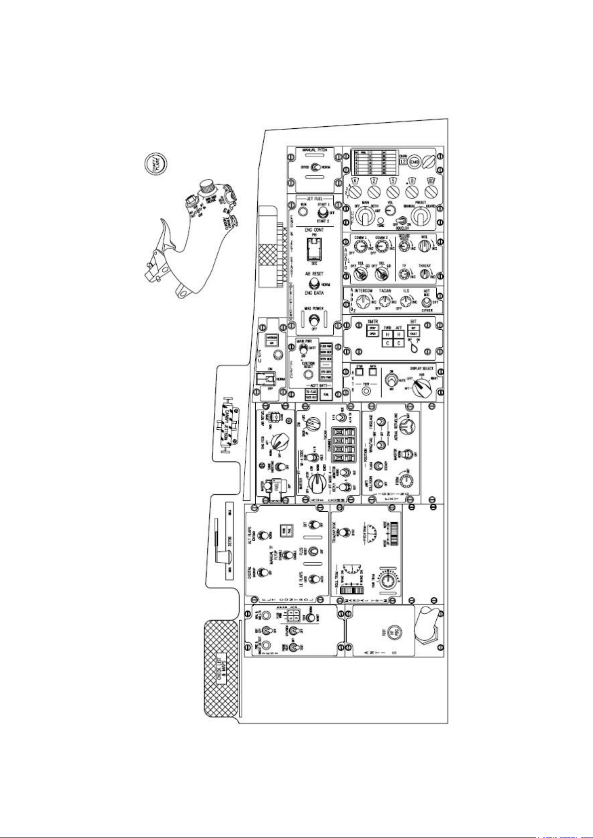
This chapter will review all cockpit panels and explain the functionality of each one. We will start on the
far left of the cockpit and move toward the right console. A switch obscured by red shading means that
this switch is not currently implemented in BMS. It thus has no key callback and no mouse hotspot.
At the end of each panel paragraph you will also find a list of the relevant key callbacks for that panel.
That will hopefully help clarify the correct callbacks when a function needs to be programmed.
A more detailed explanation of callbacks can be found in the BMS-Technical-Manual.
Page 15
T.O. BMS1F-16CM-1 BMS 4.34 Change 2.00
BMS 4.34 Dash 1
© Red Dog 2012-2019 Page: 15
1.2.1. LEFT CONSOLE
Page 16
T.O. BMS1F-16CM-1 BMS 4.34 Change 2.00
BMS 4.34 Dash 1
© Red Dog 2012-2019 Page: 16
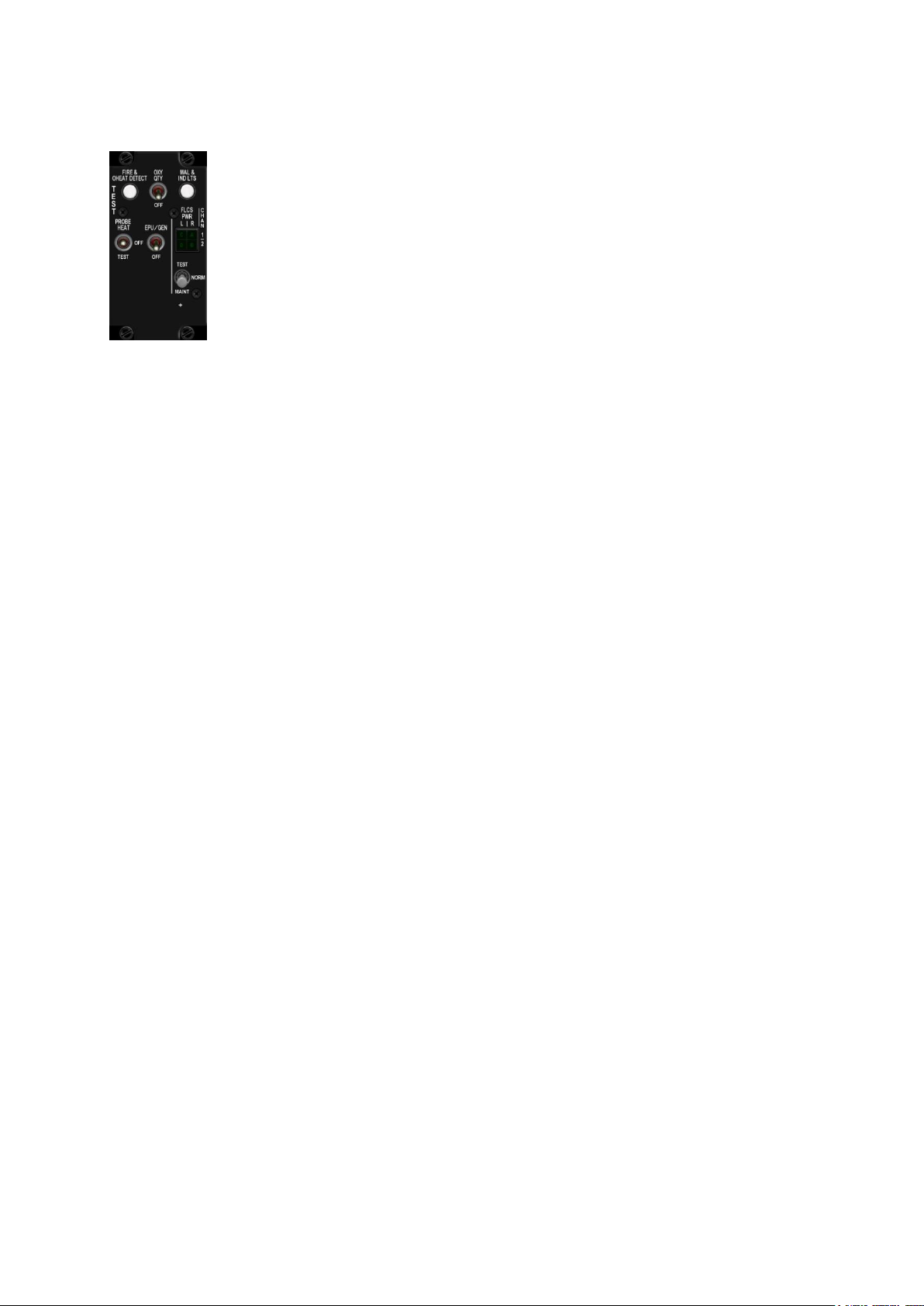
1.2.1.1 TEST panel
The TEST panel is used to perform tests on different systems during Ramp start. In
BMS all switches and push buttons are implemented, except the FLCS TEST switch in
the MAINT (Maintenance) position.
The FIRE & OHEAT DETECT button checks continuity for both engine fire and
overheat detection systems. The overheat detection happens 100°C before the engine
fire detection system. The overheat triggers the OVERHEAT caution light and the
engine fire triggers the ENG FIRE eyebrow light. Those lights and the MASTER
CAUTION light remain on as long as the button is held depressed.
The second pushbutton on the panel is MAL & IND LTS. It tests the illumination of all warning,
caution, indicator lights, the warning horn and all voice messages in sequence.
The OXY QTY is a momentary switch and tests the OBOGS (On Board Oxygen Generating System).
When depressed the OXY LOW eyebrow light should illuminate for 10 seconds if no faults are
present and remain on if a fault is detected. Please note in newer blocks this switch should be
labelled OBOGS BIT.
The PROBEHEAT switch is a three-position switch: PROBE HEAT, OFF and TEST.
The pitot, fuselage air data, AOA and the total temperature probe heaters are on anytime the aircraft
is airborne regardless of the TEST panel switch position.
The PROBEHEAT position allows the probes to be heated on the ground. OFF de-energizes all
systems on the ground. TEST (on the ground and in-flight) performs a functional test of the
PROBEHEAT monitoring system. The PROBEHEAT caution light flashes for a successful test.
Failure of the PROBEHEAT caution light to illuminate or flash indicates a failure of the probe heat
monitoring system.
The EPU/GEN test switch is spring loaded to the OFF position and provides a means to test the EPU
generator and EPU PMG output to FLCS on the ground without using hydrazine. Hydrazine is highly
toxic for ground personnel and special procedures have to be followed when the EPU has run on
hydrazine.
The quad indicator labelled FLCS PWR is the indicator of the 4 redundant digital systems (ABDC) of
the FLCS (Flight Control System). In BMS they are considered as one and always light up together.
The FLCS PWR TEST switch is a momentary switch to TEST. With the MAIN PWR switch in BATT it
closes the FLCS relay and allows verification of power output to the FLCC (Flight Control Computer)
with the aircraft battery as the power source.
BMS Key Callbacks for the test panel:
SimOverHeat
SimOBOGSBit
SimMalIndLights
SimMalIndLightsOFF
SimProbeHeatMoveDown
SimProbeHeatMoveUp
SimProbeHeatOn
SimProbeHeatOff
SimProbeHeatTest
SimEpuGenTest
SimFlcsPowerTest
Page 17
T.O. BMS1F-16CM-1 BMS 4.34 Change 2.00
BMS 4.34 Dash 1
© Red Dog 2012-2019 Page: 17
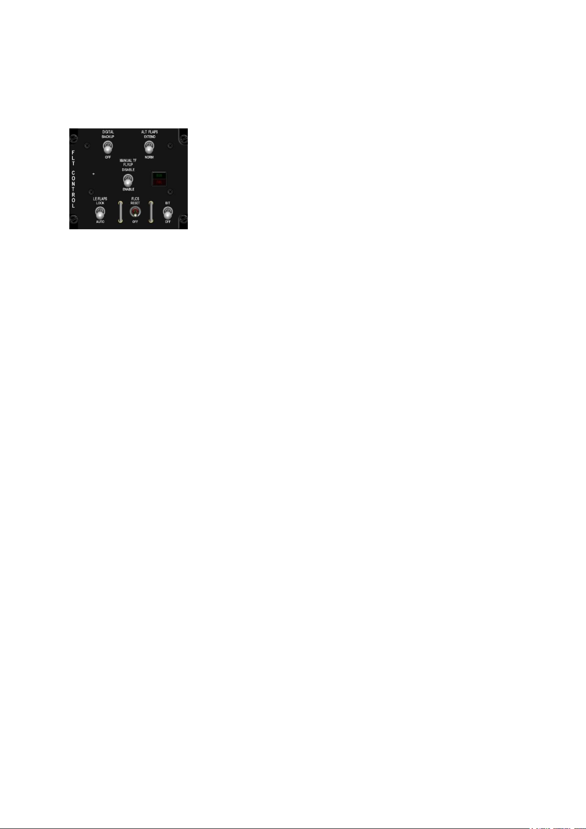
1.2.1.2 FLT CONTROL Panel (FLCP)
Refer to the FLCS chapter for a full overview of the FLCS system.
The panel is made of 6 switches and 1 dual indicator light.
The DIGITAL BACKUP switch is a two-position switch allowing the pilot
to manually select a backup software state of the FLCS for digital FLCS
equipped aircraft. When DBU is engaged the FLCS MFD page and the
DBU ON warning light report the DBU condition. A HUD WARN message
is also displayed.
The ALT FLAPS EXTEND/NORM switch controls the trailing edge flaps.
In NORM they are controlled automatically by the FLCS. To extend them manually place the switch in
EXTEND.
The LE FLAPS LOCK/AUTO switch commands the leading edge flaps. They can be automatically
controlled by the FLCS in AUTO position (as a function of Mach, altitude and AOA) or locked in their
current position in LOCK. When in LOCK the FLCS warning light illuminates and the PFLD reports a
>FLCS LEF LOCK< warning message.
The FLCS RESET switch is a momentary switch to RESET and allows the FLCS fault to be reset.
The MASTER CAUTION reset doesn’t clear FLCS related faults so the only way to reset the
indicators, warning lights and PFL is by using the FLCS RESET switch. FLCS faults may be reset in
BMS to exit the FLCS standby gains activated on any FLCS fault (see FLCS section). Not all faults
can be reset.
The MANUAL TF FLYUP switch is a two-position toggle switch. It allows you to disable or enable
FLYUP protection in MANUAL TF (Terrain Following) mode. Only aircraft fitted with the AN/AAQ-13
navigation pod (NVP), part of the LANTIRN (Low Altitude Navigation and Targeting Infrared for Night)
system, will have Terrain Following Radar (TFR) capability.
The BIT switch is a magnetically held switch in BIT. It performs the FLCS built in test if the weight on
wheel switch is on. BIT takes about 45 seconds, during which the RUN green indicator light is
illuminated. During the BIT all flight control surfaces move in sequence (these movements are visible
in multiplayer). If the BIT is successful the switch snaps back to the OFF position and the RUN light
goes off.
In case of failure the switch returns to OFF and the yellow FAIL light illuminates. The PFL displays
FLCS BIT FAIL and the status of the FLCS BIT is also shown on the FLCS MFD page. A failed BIT is
not resettable and a new BIT needs to be run. During that second BIT both the FAIL and RUN lights
will remain illuminated and upon successful completion the FAIL light will go off.
BMS Key Callbacks for the FLCS panel:
SimDigitalBUPBackup
SimDigitalBUPOff
SimDigitalBUP (new toggle)
SimAltFlaps (toggle)
SimAltFlapsExtend
SimAltFlapsNorm
SimManualFlyupDisable
SimManualFlyupEnable
SimManualFlyup (toggle)
SimLEFLockSwitch
SimLEFLock
SimLEFAuto
SimFLCSReset
SimFLTBIT
Page 18
T.O. BMS1F-16CM-1 BMS 4.34 Change 2.00
BMS 4.34 Dash 1
© Red Dog 2012-2019 Page: 18
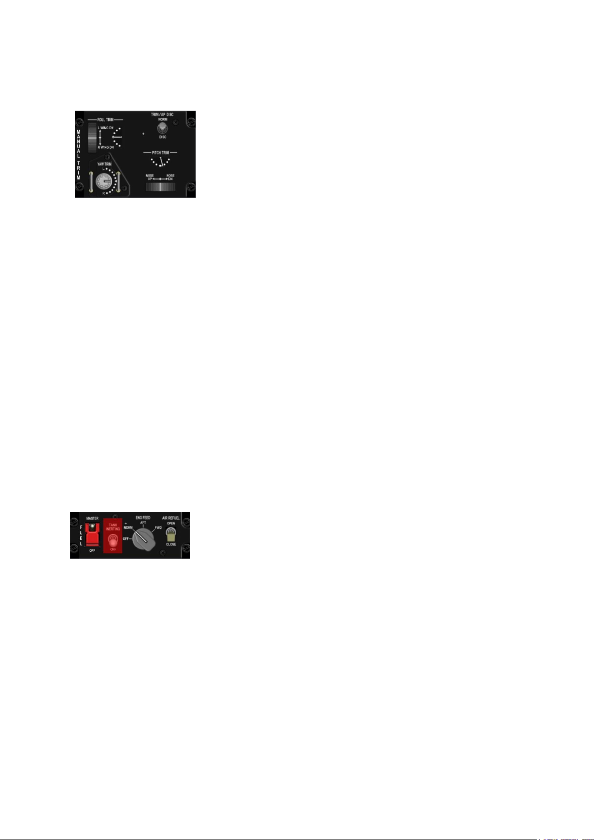
1.2.1.3 MANUAL TRIM panel
The Manual TRIM panel provides an additional method for the pilot to
trim the aircraft. Primary trims (roll & pitch) are on the stick. The wheels
and indicators on the MANUAL TRIM provide a backup way to set the
trims by using the relevant wheel or knob.
Rudder trim can only be set on the MANUAL TRIM panel via the YAW
TRIM knob.
In the F-16 trim is often required, especially in asymmetric load
conditions. The 2 indicators move with stick trim input (when energised)
and/or manual trim input. The wheels have a white line marking their centre position.
The TRIM/AP DISC switch is a two-position toggle switch. In NORM the stick trims are energized and
AP operation is possible.
In DISC the stick trims and the autopilot are inhibited. Manual trim remains operative.
The MANUAL TRIM wheels and knobs can be interfaced through keystrokes, mouse clicks or
analogue hardware such as potentiometers. The latter solution gives much better and smoother
results. A little warning about mouse clicks: the way they are implemented is almost impossible to
manage correctly in flight and should be avoided. Left click starts the trim movement and right click
stops the trim action and starts the action in the opposite way. If you need to use the manual trims do
it with keystrokes or analogue devices, not the mouse. Note that the YAW TRIM knob does not move
in BMS when rudder trim is implemented and as a consequence you have no reference for the YAW
TRIM position.
BMS Key Callbacks for the MAN TRIM panel:
SimTrimAPDisc (toggle)
SimTrimAPDISC (DISC switch position)
SimTrimAPNORM (NORM switch position)
SimTrimNoseUp
SimTrimNoseDown
SimTrimRollLeft
SimTrimRollRight
SimTrimYawLeft
SimTrimYawRight
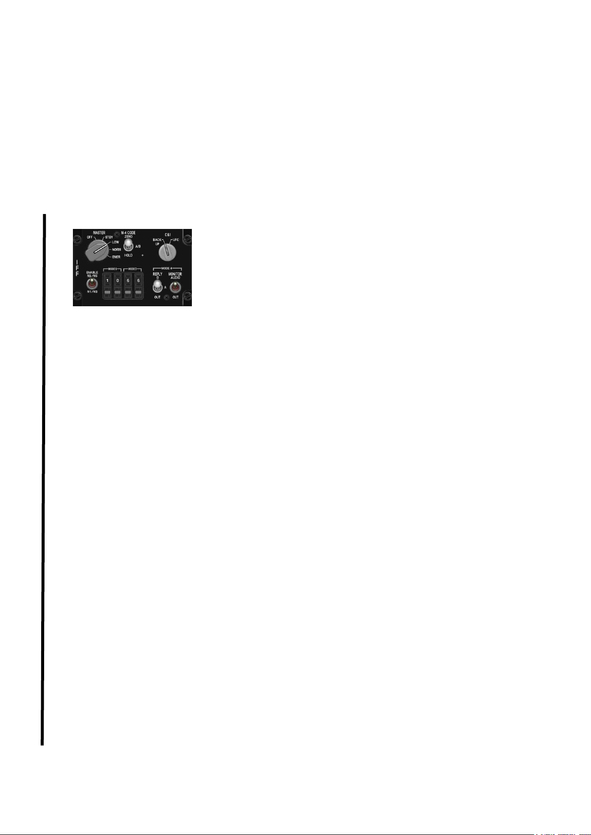
1.2.1.4 FUEL panel
The FUEL MASTER switch is guarded in MASTER position. In some
airforces the guard is even secured in place with a wire. This switch is
not operated by the pilot in normal operations. When placed in OFF the
fuel shutoff valve is closed, preventing fuel from reaching the engine.
The TANK INERTING switch is unsupported in BMS. In the real jet it reduces internal tank
pressurisation.
The ENG FEED knob controls the way the fuel is pumped to the engine. Note that the fuel goes to the
engine by gravity feed, so the engine will not starve when the fuel pumps are OFF. Use of the pumps
prevents fuel starvation during negative G maneuvers and allows manual fuel balance whenever
necessary.
OFF - all pumps are off.
NORM - all pumps are on, the CG (Centre of Gravity) is maintained automatically.
AFT - aft pumps are on. Fuel is transferred from the AFT tank to the engine. The CG moves forward.
FWD – forward pumps are on. Fuel is transferred from the FWD tank to the engine. CG moves back.
The AIR REFUEL switch is a two-position toggle switch. It opens or closes the Air Refuelling door.
Upon opening the AR door the FLCS switches to takeoff and landing gains (if airspeed is below 400
knots). It also reduces internal tank pressurisation and depressurises external tanks, so they can be
filled at air to air refuelling.
Page 19
T.O. BMS1F-16CM-1 BMS 4.34 Change 2.00
BMS 4.34 Dash 1
© Red Dog 2012-2019 Page: 19
BMS Key Callbacks for the FUEL panel:
SimToggleMasterFuel
SimMasterFuelOn
SimMasterFuelOff
SimDecFuelPump
SimIncFuelPump
SimFuelPumpOff
SimFuelPumpNorm
SimFuelPumpAft
SimFuelPumpFwd
SimFuelDoorToggle
SimFuelDoorOpen
SimFuelDoorClose
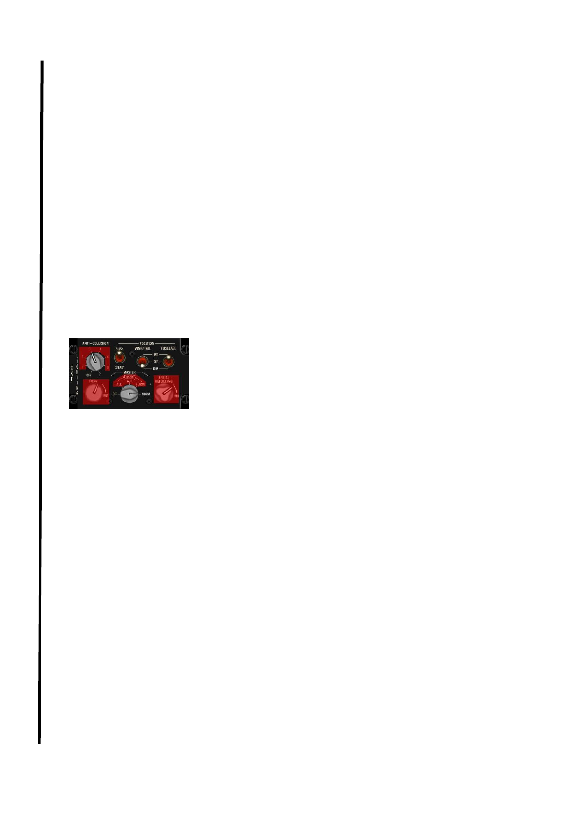
1.2.1.5 IFF panel
BMS 4.34 introduced a fully implemented IFF system and the AUX
COMM panel has been replaced with the IFF panel in some AIFF
equipped aircraft. Backup TACAN controls have been moved to a MFD
page and have been replaced by backup IFF controls. Please note,
some non AIFF aircraft still have the AUX COMM panel (see below).
For more information about the IFF system, please refer to Chapter 1.16
IFF.
The IFF MASTER knob controls power to the IFF transponder/interrogator unit..
in OFF the system is unpowered. In STBY the system is powered but unable to answer IFF
interrogations. In LOW the IFF is operating normally (can interrogate) but responds to interrogation at
half effective distance (reduced interrogation range). NORM is the normal operation position; the IFF
can interrogate and respond to interrogations.
In EMER, the IFF can interrogate but responds to interrogations with a fixed emergency code:
(Mode 1: 70; Mode 2: 7777 and Mode 3: 7700; Mode C and Mode 4 response is normal)
The M-4 CODE switch controls how the IFF responds to mode-4 interrogations.
A/B is the normal operation position; the IFF uses the normal secret key that is either stored in A or B
bank (set in UFC for normal operations and set with the Mode 4 reply switch in backup mode).
In ZERO, both code A and code B are erased from memory when the position is held for 2 seconds
(keys are also erased automatically upon shutdown).
In HOLD, power-off zeroing is temporarily disabled and the Mode 4 codes are saved.
The CNI knob allows the pilot to toggle between the BACKUP system and the UFC (Up Front
Controller). The heart of the F-16 cockpit is the UFC made of the ICP, the DED and the two MFDs.
Those need the main generator running and are thus unavailable at ramp start, shut down or in the
event of malfunction or battle damage. In that case the CNI switch needs to be placed in BACKUP
which provides alternate operation of the UHF, IFF and other systems.
The IFF enable switch enables control of IFF modes in backup mode (CNI in Backup position).
Normal IFF controls are set through the IFF UFC pages (more information in the UFC chapter)
M1/M3 enables Mode 1 and Mode 3 responses with the relevant codes inputted in the backup IFF
digits codes.
M3/MS enables Mode 3 and Mode S responses (Mode S is not implemented in BMS 4.34).
The digit selectors of the IFF panel are relevant to Mode 1 and Mode 3 IFF codes. Do not confuse
them with the old TACAN channel digit selectors on the AUX COMM panel.
The MODE 4 REPLY switch is a three-position switch that controls the Mode 4 reply in backup mode
OFF: no response to mode4 interrogation. A: reply to Mode 4 interrogations with code A, B: reply to
Mode 4 interrogations with code B.
The MODE4 MONITOR switch enables AUDIO feedback of the IFF system in AUDIO position. No
audio feedback is provided in OUT position. Audio feedback is a tone which signals the inability of the
system to answer a Mode 4 interrogation correctly.
Page 20

T.O. BMS1F-16CM-1 BMS 4.34 Change 2.00
BMS 4.34 Dash 1
© Red Dog 2012-2019 Page: 20
Although not the case for block 50 & block 52 F-16, some other F-16
models may still have the AUX COMM panel installed. The main
difference with the IFF panel documented above is the possibility to
manage the backup TACAN controls rather than the backup IFF controls.
The lower right part of the panel allows the pilot to set a TACAN channel,
band and mode when the CNI switch is in BACKUP. The TACAN
channel is set into the first three windows. The fourth window is used to
set the X or Y band.
The T/R, A/A TR switch provides control of TACAN functions when the CNI switch is in BACKUP.
T/R is Transmit / Receive mode. The system receives signals which result in bearing and course
deviation on the HSI and transmit distance interrogation to the station to get DME information.
REC (Receive) is not implemented.
A/A TR is the Air to Air Transmit and Receive mode. The system interrogates and receives signals
from aircraft having air to air capability, providing slant range (Nm) distance between aircraft
operating 63 TACAN channels apart. (The KC-10 also provides bearing information).
BMS Key Callbacks for the AUX COMMS panel:
SimIFFMasterOff
SimIFFMasterStby
SimIFFMasterLow
SimIFFMasterNorm
SimIFFMasterEmerg
SimIFFMasterInc
SimIFFMasterDec
SimIFFCodeSwitchZero
SimIFFCodeSwitchHold
SimIFFEnableOff
SimIFFEnableM1M3
SimIFFEnableM3MS
SimIFFEnableInc
SimIFFEnableDec
SimIFFEnableCycle
SimIFFBackupM1Digit1Inc
SimIFFBackupM1Digit1Dec
SimIFFBackupM1Digit1_0
SimIFFBackupM1Digit1_1
SimIFFBackupM1Digit1_2
SimIFFBackupM1Digit1_3
SimIFFBackupM1Digit1_4
SimIFFBackupM1Digit1_5
SimIFFBackupM1Digit1_6
SimIFFBackupM1Digit1_7
SimIFFBackupM1Digit2Inc
SimIFFBackupM1Digit2Dec
SimIFFBackupM1Digit2_0
SimIFFBackupM1Digit2_1
SimIFFBackupM1Digit2_2
SimIFFBackupM1Digit2_3
SimIFFBackupM3Digit1Inc
SimIFFBackupM3Digit1Dec
SimIFFBackupM3Digit1_0
SimIFFBackupM3Digit1_1
SimIFFBackupM3Digit1_2
SimIFFBackupM3Digit1_3
SimIFFBackupM3Digit1_4
SimIFFBackupM3Digit1_5
SimIFFBackupM3Digit1_6
SimIFFBackupM3Digit1_7
SimIFFBackupM3Digit2Inc
SimIFFBackupM3Digit2Dec
SimIFFBackupM3Digit2_0
SimIFFBackupM3Digit2_1
SimIFFBackupM3Digit2_2
SimIFFBackupM3Digit2_3
SimIFFBackupM3Digit2_4
SimIFFBackupM3Digit2_5
SimIFFBackupM3Digit2_6
SimIFFBackupM3Digit2_7
Page 21
T.O. BMS1F-16CM-1 BMS 4.34 Change 2.00
BMS 4.34 Dash 1
© Red Dog 2012-2019 Page: 21
SimIFFMode4ReplyOff
SimIFFMode4ReplyAlpha
SimIFFMode4ReplyBravo
SimIFFMode4ReplyInc
SimIFFMode4ReplyDec
SimIFFMode4ReplyCycle
SimIFFMode4MonitorOff
SimIFFMode4MonitorAud
SimIFFMode4MonitorToggle
SimToggleAuxComMaster
SimAuxComBackup
SimAuxComUFC
SimCycleLeftAuxComDigit (cycle = move up)
SimDecLeftAuxComDigit (dec= move down)
SimCycleCenterAuxComDigit
SimDecCenterAuxComDigit
SimCycleRightAuxComDigit
SimDecRightAuxComDigit
SimCycleBandAuxComDigit
SimXBandAuxComDigit
SimYBandAuxComDigit
SimTACANTR
SimTACANAATR
SimToggleAuxComAATR (toggle)
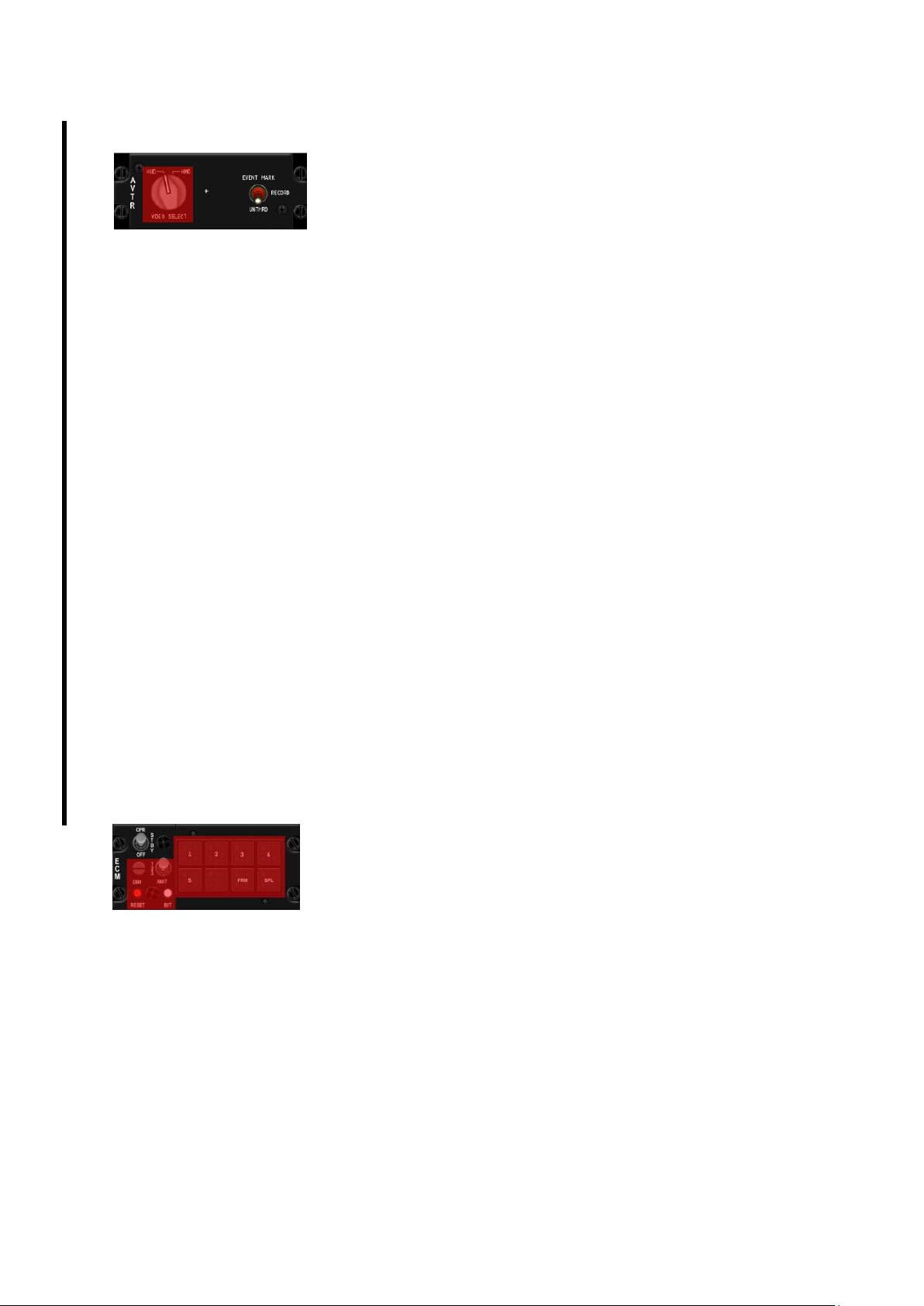
1.2.1.6 EXT LIGHTING panel
All exterior lights except the taxi light are controlled from this panel.
The panel has been updated with 4.34 but functionalities remain the
exact same as before.
The ANTI-COLLISION switch has been replaced by an anti-collision
knob. But only two positions are implemented: OFF (Left-most position
and ON (Right-most position corresponding to C.
It toggles the white anti-collision strobe situated on top of the tail.
The AC light is always flashing at the same frequency in BMS.
The POSITION FLASH/STEADY switch is a two-position toggle switch as well and is relevant only to
the position lights (wingtips and fuselage) in BMS. In FLASH the wingtip and fuselage lights flash at a
set frequency. In STEADY the lights remain on constantly.
In BMS the fuselage (intake), wingtips and tail position lights are considered a single entity and as
such one switch drives them all. In the cockpit both the WING/TAIL and FUSELAGE switches move
together. Normally the FUSELAGE switch refers to the tail floodlights but those are not implemented in
BMS. The DIM position is also not implemented and we only can set them OFF or BRT (bright).
The MASTER light switch has also been replaced by a MASTER knob of which only 2 positions are
implemented (OFF & NORM). The COVERT options (IR) are not implemented either.
As its name implies is the main switch for all lights. Toggling this one OFF will switch off all lights
except the taxi light. Conversely, this switch needs to be in NORM for exterior lights to work as set
(except the taxi light).
Both the FORM and AERIAL REFUELING knobs are not implemented.
BMS Key Callbacks for the EXT LIGHT panel:
SimExtlMasterNorm
SimExtlMasterOff
SimExtlPower (toggle)
SimExtlAntiColl (toggle)
SimAntiCollOn
SimAntiCollOff
SimExtlSteady (toggle)
SimLightsSteady
SimLightsFlash
SimExtlWing (toggle)
SimWingLightBrt
SimWingLightOff
Page 22
T.O. BMS1F-16CM-1 BMS 4.34 Change 2.00
BMS 4.34 Dash 1
© Red Dog 2012-2019 Page: 22
1.2.1.7 AVTR panel
This panel is used to toggle the ACMI on and off.
As you can see this panel has been updated since 4.33.
But unfortunately not for the best. The very useful green AVTR indicator
light has been removed and the switch used to turn the ACMI ON is
mislabelled and does not follow the common direction of all other
cockpit switches. The VIDEO Select switch is not implemented. The old ON/AUTO/OFF switch has
been replaced by a 3-position switch labelled UNTHRD, RECORD & EVENT MARK.
UNTHRD means OFF and is the default position.
EVENT MARK is mislabelled in BMS as in real life this is used to mark a specific point on the tapes
(index) but in BMS it is the old AUTO position where the ACMI will turn ON for 30 seconds upon a
gun trigger or a weapon pickle action.
RECORD is the old ON position where the ACMI is turned ON manually.
The problem is that this 3-position switch does not follow the common logic of all the rest of the 3D
cockpit. To place the switch out of UNTHRD, you must click left as usual. But this action doesn’t move
the switch (as logic would dictate) to ON but straight to EVENT MARK. To move to record, you still
must left click with the switch on EVENT MARK to move the switch down to RECORD. Normally a
move down should be a right click.
So basically, to record an ACMI with the mouse, click twice with the left mouse button. And to place it
back to OFF, click twice with the right mouse button.
Note that an option in Falcon BMS.cfg (in the \User\Config folder) lets you choose whether to display
the ACMI RECORDING message on screen or not. Back in 4.33 we advised not to use it and use the
green AVTR indicator light instead? Unfortunately, with 4.34 that ACMI message might be unrealistic
but it is your sole option to indicate ACMI status.
BMS Key Callbacks for the AVTR panel:
SimAVTRSwitch (cycle)
SimAVTRToggle (toggle)
SimAVTRSwitchOff
SimAVTRSwitchAuto
SimAVTRSwitchOn
SimAVTRSwitchDown (step down)
SimAVTRSwitchUp (step up)
1.2.1.8 ECM panel
Due to its nature and the fact that most ECM systems are classified, this
panel is not implemented. The only switch used in BMS is the main
toggle switch, labelled OPR, STBY, OFF.
BMS only uses the ON/OFF position and that switch needs to be placed
in OPR for the ECM pod to be energized (if carried).
BMS Key Callbacks for the ECM panel:
SimEcmPowerOn
SimEcmPowerOff
SimECMPower (toggle)
Page 23

T.O. BMS1F-16CM-1 BMS 4.34 Change 2.00
BMS 4.34 Dash 1
© Red Dog 2012-2019 Page: 23
1.2.1.9 ELEC panel
The real electrical system of the F-16 is quite complicated with a main AC power
system distributing current to the non-essential, essential and emergency buses, a
standby AC power system distributing power to the essential and emergency buses,
an emergency AC power supply distributing power to the emergency buses and a DC
power and FLCS power supply.
The main power switch is a three-position switch.
In OFF no electrical system receives power from the main generator, standby generator or battery. All
systems are cold.
In BATT the aircraft battery is connected and the battery bus is powered.
In MAIN the MAIN generator and standby generator provide power to the aircraft systems.
The CAUTION RESET push button is the only way to reset an ELEC fault, displayed as the amber
ELEC SYS caution light. It also resets the main and standby generators.
FLCS PMG indicator light: when it lights up it means that none of the FLCS branches are receiving
power from the FLCS PMG (Permanent Magnet Generator). Basically that means the primary power
source for the FLCS has failed.
When the MAIN GEN indicator comes on it means that the main generator is not connected to the
non-essential AC buses. In all likelihood the main generator has failed.
Likewise, when the STBY GEN indicator light up it means that standby generator power is not
available.
When the EPU GEN indicator light comes on it means the EPU has been commanded ON but the
EPU generator is not providing power to the emergency buses. Be aware that the light does not
function with the EPU in OFF (WOW) and the engine running.
When the EPU PMG indicator light comes on it means that the EPU has been commanded ON but
the EPU is unable to provide power to the FLCS branches (normally through the EPU PMG).
The two lower indicators refer to the aircraft battery.
When the TO FLCS indicator lights up it means that the battery power is going to one or more FLCS
branches. Basically the battery is powering the FLCS and will deplete fast.
When the FLCS RLY indicator light comes on it means that one or more FLCS branches aren’t
getting adequate voltage from the battery.
When the FAIL indicator light comes up it means that the aircraft battery has failed or is failing to
charge (on the ground).
BMS Key Callbacks for the ELEC panel:
SimMainPowerOff
SimMainPowerBatt
SimMainPowerMain
SimElecReset
SimMainPowerInc (step up)
SimMainPowerDec (step down)
Page 24

T.O. BMS1F-16CM-1 BMS 4.34 Change 2.00
BMS 4.34 Dash 1
© Red Dog 2012-2019 Page: 24
1.2.1.10 EPU panel
The EPU is a self-contained system that simultaneously provides emergency hydraulic
pressure to system A and emergency electrical power to the emergency buses. The EPU
automatically activates (unless the EPU safety pin is installed) when both main and
standby generators fail or when hydraulic pressure falls below 1000 psi.
The EPU uses engine bleed air and/or hydrazine to operate. If engine bleed air is sufficient
to maintain operating speed the EPU doesn’t use hydrazine. Hydrazine is only used as a
booster when bleed air is not sufficient.
The main switch for the EPU is a double guarded three-position switch. With the guard down the
switch is locked in NORM.
OFF - the EPU is prevented from running.
NORM - the EPU is armed for automatic start upon failure of the main and standby generators, if the
throttle is out of the CUTOFF position. The EPU will not start on shutdown (WOW and throttle in
CUTOFF). On engine start the EPU pin prevents the EPU from starting up. The EPU pin should be
removed via the ATC menu > Ground page prior to the EPU test.
ON - the EPU is commanded to RUN regardless of failure conditions.
As you see on the panel the switch is guarded, but any mouse click on the switch lifts the guard and
operates the switch at the same time. In other words the guard has no effect in BMS.
The EPU RUN green light comes on whenever the EPU turbine runs within the proper range and the
EPU hydraulic pressure is above 2000 psi.
The top indicator is telling the pilot if the EPU runs on engine bleed air and/or hydrazine.
When the yellow AIR indicator lights up (bottom light) the EPU is running on bleed air which is
sufficient to maintain operating speed. If possible when the EPU runs, engine RPM should be
maintained between 82 & 90% to prevent the EPU using hydrazine. Unfortunately in Falcon when the
EPU needs to run it’s usually because we’ve lost the engine.
When the yellow HYDRAZN (top light) comes on, the bleed air is not sufficient to maintain operating
speed and is being augmented by hydrazine. In that case both indicator lights will be on.
Hydrazine is limited and usually depletes in 10 minutes under normal load requirements. Increased
flight control movement reduces this operating time further. Also bear in mind that if the EPU is your
sole source of hydraulic pressure and power, when the hydrazine is depleted you lose everything. As
a consequence when you start running on hydrazine, plan to be on the ground within the next 10
minutes or tighten your straps ready for an ejection. For more information about the EPU and which
systems are powered by the emergency bus please refer to the Electrical and EPU section later in
this manual.
BMS Key Callbacks for the EPU panel:
SimEpuToggle
SimEpuOff
SimEpuOn
SimEpuAuto
SimEpuUp (step up)
SimEpuDown (step down)
Page 25
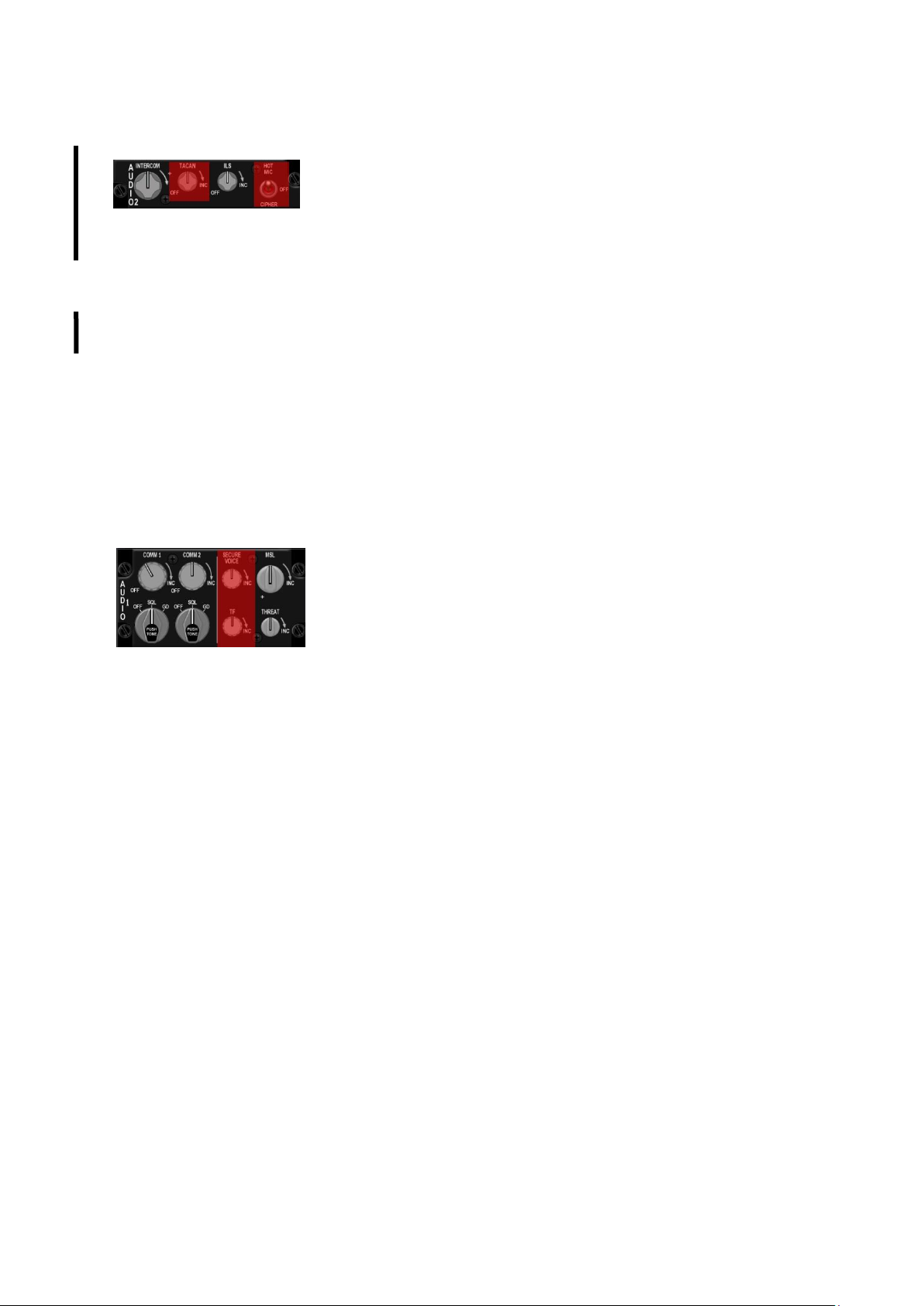
T.O. BMS1F-16CM-1 BMS 4.34 Change 2.00
BMS 4.34 Dash 1
© Red Dog 2012-2019 Page: 25
1.2.1.11 AUDIO 2 panel
The AUDIO 2 panel provides control to the less frequently used
communications system. The intercom volume knob is used to control
the volume of all sounds normally heard in the pilot’s helmet. It allows
the user to set the respective individual volumes to a desired ‘mix’ level
and then turn it up or down relative to the rest of the background sounds (those normally not heard in
the pilot’s headset).
The TACAN volume is normally used to get the morse code of the emitting station in the headset but
this is not implemented in BMS, so that volume control is not implemented. There is not even a need
to switch to knob out of OFF for the TACAN to work, it’s coded always on. Likewise there is no ILS
audio but this time the knob can be turned ON and OFF to power the ILS system. Unlike BMS 4.32
where the ILS was always on the pilot now needs to power the ILS to be able to see ILS symbology.
Finally, the HOT MIC switch is not implemented.
BMS Key Callbacks for the AUDIO2 panel:
SimILSOn
SimILSOff
SimILS (toggle)
SimStepIntercomVolumeUp
SimStepIntercomVolumeDown
1.2.1.12 AUDIO 1 panel
The AUDIO 1 panel controls the primary communication systems.
Unless otherwise specified, the controls are active regardless of the
position of the CNI switch on the AUX COMM panel.
The COMM1 power knob has an ON/OFF switch and when rotated past
the ON position increases volume for the COMM1 radio (UHF). This
control can be set through an analogue potentiometer via the advanced
setup, or with regular keystrokes.
The COMM1 mode knob has three-position: OFF, SQL and GD.
In OFF squelch mode is disabled (though squelch is not implemented in BMS).
In SQL the squelch mode is activated helping reduce background noise in normal operations.
In GD the main receiver and transmitter are tuned to the guard UHF frequency (243.000). Please note
GD position is not functional when the CNI is in BACKUP (guard is then selected from the backup
UHF panel).The push function is not implemented in BMS.
The COMM2 power and mode knobs have the same functions, but for the second radio (VHF).
GD position tunes to VHF guard (121.5).
The secure voice and TF knobs are not supported in BMS.
The MSL knob is used to set the sidewinder missile acquisition sound level. This control can be set
through an analogue potentiometer via the advanced setup or with regular keystrokes. The knob has
no ON/OFF position so at ramp and during your FENCE check you should check its position, unless
you use a potentiometer to interface it. In that case the volume is set at whatever position the pot was
left during the last flight.
The THREAT knob is used to set the TWS (Threat Warning System) sound level. This control can be
set either with an analogue potentiometer via the advanced setup or with regular keystrokes.
The knob has no ON/OFF position and at ramp and during your FENCE check you should check its
position unless you use a potentiometer to interface it. In that case the volume is set at whatever
position the pot was left during the last flight.
Page 26
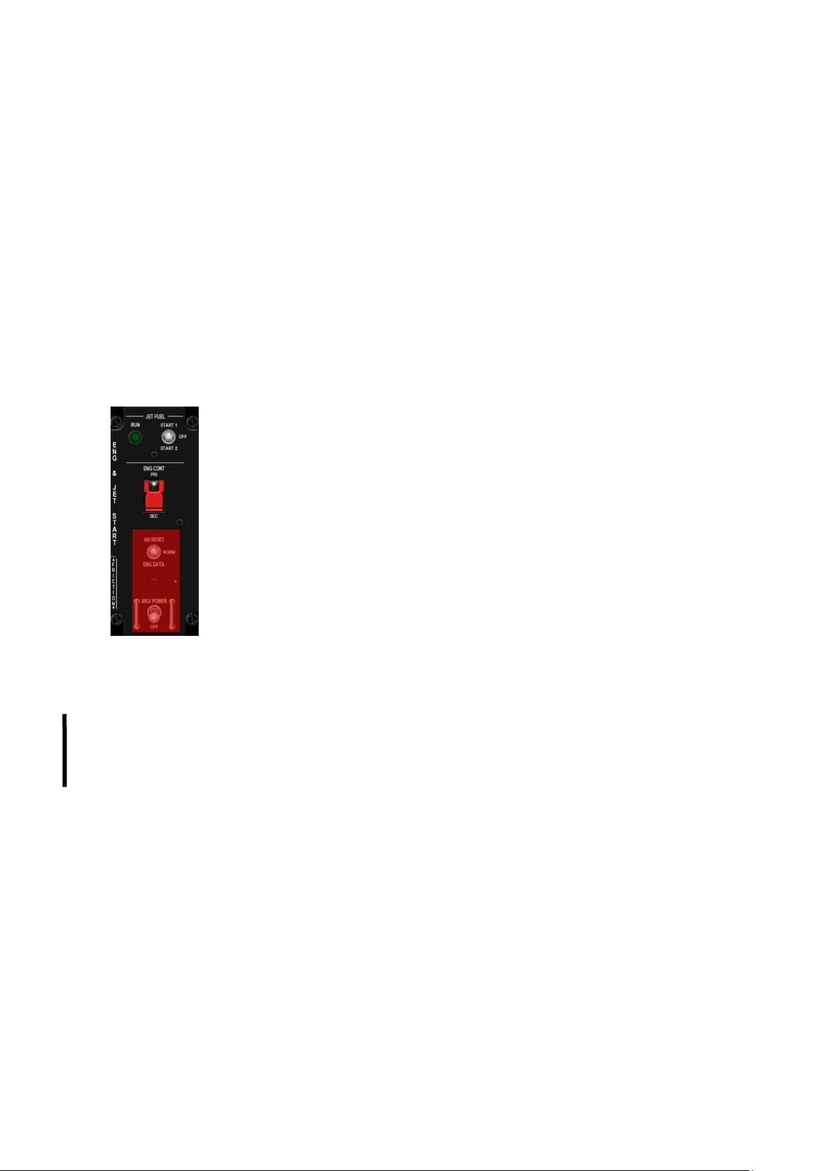
T.O. BMS1F-16CM-1 BMS 4.34 Change 2.00
BMS 4.34 Dash 1
© Red Dog 2012-2019 Page: 26
BMS Key Callbacks for the AUDIO1 panel:
SimStepComm1VolumeUp
SimStepComm1VolumeDown
SimComm1PowerOn
SimComm1PowerOff
SimStepComm2VolumeUp
SimStepComm2VolumeDown
SimComm2PowerOn
SimComm2PowerOff
SimStepMissileVolumeUp
SimStepMissileVolumeDown
SimStepThreatVolumeUp
SimStepThreatVolumeDown
SimAud1Com1Sql
SimAud1Com1Gd
SimAud1Com1 (toggle)
SimAud1Com2Sql
SimAud1Com2Gd
SimAud1Com2 (toggle)
1.2.1.13 ENG & JET START panel
The main purpose of this panel is to start the engine. This is done using the JFS
(Jet Fuel Starter) switch. The JFS is an independent gas turbine and is started by 2
JFS/brake accumulators which are charged automatically by hydraulic system B.
The JFS is used to start the engine on the ground and to assist in engine airstarts.
The switch is a magnetically held 3-position switch, magnetically held in START1
or START2. Currently in BMS we only use the START 2 position with a RIGHT
mouse click (down is always right click).
When placed in START 2 the JFS spools up and drives the main engine turbine
shaft RPM to 20-25%. If you have a suitable throttle (with a strong idle detent) and
have the Idle Cutoff option box checked in Falcon BMS.cfg the throttle can then be
moved out of its CUTOFF position to IDLE, which starts the main engine as it does
in the real jet. In BMS this can also be done with the throttle detent key callback.
The JFS/brake accumulator starts to recharge past 12% engine RPM with HYD B pressure and takes
between 40 and 60 seconds to regain a full operating pressure charge. The JFS automatically shuts
down when the engine RPM passes 55%. The switch then snaps back to OFF.
Since BMS 4.33 the green JFS run light no longer comes on as soon as the JFS is activated but
illuminates around 15 seconds later once the JFS has attained nominal operating speed.
In 4.34 the JFS light state will indicate JFS status: a JFS light flashing once every second will indicate
a JFS overheat and a JFS light flashing twice per second will indicate a JFS failure.
The ENG CONT PRI/SEC is a two-position switch guarded in PRI, which is the normal (primary)
engine operating mode. The engine transfers automatically to SEC mode in the case of any failure of
the Digital Electronic Control (DEC). It can manually be transferred to SEC by placing the ENG CONT
switch in SEC. Transfer is indicated by the SEC caution light on the warning panel. When operating in
SEC the engine exhaust nozzle remains closed and afterburner is inhibited (nozzle is now visible in
multiplayer).
The AB RESET and MAX POWER switches are not implemented in BMS.
BMS Key Callbacks for the ENG & JET START panel:
SimJfsStart (toggle)
SimJfsStart_Start2
SimJfsStart_off
SimEngCont (toggle)
SimEngContPri
SimEngContSec
Page 27
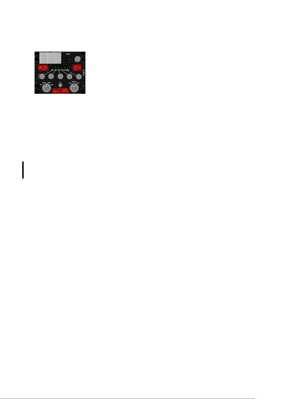
T.O. BMS1F-16CM-1 BMS 4.34 Change 2.00
BMS 4.34 Dash 1
© Red Dog 2012-2019 Page: 27
1.2.1.14 Backup UHF panel
The only backup radio available in the F-16 cockpit is the UHF radio. There
is no backup mode for the VHF radio. For the UHF backup radio to operate,
the C&I switch on the IFF (or AUX COMM) panel needs to be in the
BACKUP position.
With the right mode knob in MNL (manual) any valid frequency is selectable
using the frequency control knobs.
The left mode knob has 4 positions but only 3 are used in BMS: OFF, MAIN & BOTH. ADF is not
supported. In OFF the backup UHF is not powered.
In MAIN, and as long as the COMM1 power switch on the AUDIO1 panel is ON, the UHF radio
operates on the selected preset channel (displayed above on the 2-digit display) or in manual mode.
In BOTH the radio works as in MAIN but can also receive transmissions on the UHF GUARD
frequency. Note, receive only!
The right mode functions knob has three positions: MNL, PRESET and GUARD.
MNL prioritises the manual frequency. In PRESET the frequency is determined by the channel knob
and indicated by the 2-digit display. In GRD the main receiver and transmitter are automatically tuned
to the UHF guard frequency.
The channel knob selects one of the 19 presets available. In BMS those presets are automatically set
with the Falcon BMS.cfg config line: set g_bInitBUPfromDTC 1.
By default the panel selects channel 6, but this is also configurable in the [your callsign].ini file
COMMS section.
The tiny volume knob has been implemented (with analogue values as well) to balance IVC volume
against AI volume. It is not the real function of that knob, but quite useful in Falcon where AI comms
do not follow the same logic as IVC humans comms on UHF & VHF.
BMS Key Callbacks for the BACKUP UHF panel
SimCycleRadioChannel
SimDecRadioChannel
SimBupUhfOff
SimBupUhfMain
SimBupUhfBoth
SimBupUhfPreset
SimBupUhfGuard
SimBupUhfManual
SimBupUhfFuncDec
SimBupUhfFuncInc
SimBupUhfModeDec
SimBupUhfModeInc
OTWBalanceIVCvsAIUp
OTWBalanceIVCvsAIDown
SimBupUhfFreq1Inc
SimBupUhfFreq1Dec
SimBupUhfFreq1_2
SimBupUhfFreq1_3
SimBupUhfFreq2Inc
SimBupUhfFreq2Dec
SimBupUhfFreq2_0
SimBupUhfFreq2_1
SimBupUhfFreq2_2
SimBupUhfFreq2_3
SimBupUhfFreq2_4
SimBupUhfFreq2_5
SimBupUhfFreq2_6
SimBupUhfFreq2_7
SimBupUhfFreq2_8
SimBupUhfFreq2_9
SimBupUhfFreq3Inc
SimBupUhfFreq3Dec
SimBupUhfFreq3_0
SimBupUhfFreq3_1
Page 28

T.O. BMS1F-16CM-1 BMS 4.34 Change 2.00
BMS 4.34 Dash 1
© Red Dog 2012-2019 Page: 28
SimBupUhfFreq3_2
SimBupUhfFreq3_3
SimBupUhfFreq3_4
SimBupUhfFreq3_5
SimBupUhfFreq3_6
SimBupUhfFreq3_7
SimBupUhfFreq3_8
SimBupUhfFreq3_9
SimBupUhfFreq4Inc
SimBupUhfFreq4Dec
SimBupUhfFreq4_0
SimBupUhfFreq4_1
SimBupUhfFreq4_2
SimBupUhfFreq4_3
SimBupUhfFreq4_4
SimBupUhfFreq4_5
SimBupUhfFreq4_6
SimBupUhfFreq4_7
SimBupUhfFreq4_8
SimBupUhfFreq4_9
SimBupUhfFreq5Inc
SimBupUhfFreq5Dec
SimBupUhfFreq5_00
SimBupUhfFreq5_25
SimBupUhfFreq5_50
SimBupUhfFreq5_75
1.2.1.15 MANUAL PITCH override panel
The MPO switch is a two-position switch momentary in OVRD. It provides a means for
the pilot to override FLCS pitch and give direct control of the elevators to the pilot.
There is a stable trim point around 60° AOA which allows the aircraft to enter a deep
stall. In this configuration the FLCS will always command maximum elevator pitch
down angle, but in this configuration the aircraft will remain in the deep stall.
In such a deep stall the pilot needs to override the FLCS and pitch-rock the aircraft to exit the stall
condition. The MPO can be tested at ramp. Simply move the elevator to its fullest extent and hold the
MPO switch in OVRD. Notice the increased elevator angle as long as the switch is held in the
override position (this is also now visible in multiplayer).
BMS Key Callbacks for the MPO panel
SimMPO
SimMPOToggle
1.2.1.16 Throttle grip and left side wall
The left sidewall has two important hotspots. Hotspots are areas where the mouse turns into a
selective zone where a switch can be clicked.
The first one is the canopy area. Normally the canopy switch is hidden inside the left sidewall and
protected with the yellow spider. The spider is just a switch guard. But in BMS it is the switch itself if
you are using the mouse to operate it. Click on the spider hotspot to open or close the canopy.
Alternately you can use the keystroke callback. The mission starts with the canopy open at Ramp
start in BMS.
With the Idle Cutoff option disabled (in Falcon BMS.cfg) the idle detent needs to be depressed when
the JFS has spooled up the engine to 20% RPM in order to start the engine. It was done so to
simulate moving the throttle from the vertical CUTOFF position to the horizontal idle position. Likewise
to shut the engine down the idle detent needs to be depressed when the throttle is idle for the engine
to spool down. This was done to simulate lifting the throttle out of the idle position to the vertical
CUTOFF position. Note that the idle detent only works when your throttle is all the way back (at its
minimum).
There is a third feature on the left side wall that may be of interest: the SLAP switch. This is a
pushbutton programmed to drop countermeasures program 5. The pilot usually slaps it in the real jet
Page 29

T.O. BMS1F-16CM-1 BMS 4.34 Change 2.00
BMS 4.34 Dash 1
© Red Dog 2012-2019 Page: 29
(don’t try in the sim!) It does however give you a third countermeasures program immediately
available without switching the PGRM knob on the CMDS. There is no mouse hotspot for the SLAP
switch in the 3D cockpit so you will have to use the key callback which you can assign to any
hardware button.
Not on the side wall but close to the left console you will find the seat arm lever on the left edge of the
seat. This lever safes/arms the ejection seat. The lever in the UP position safes the seat and the lever
in the DOWN position arms the seat.
BMS Key Callbacks for the left side panel:
AFCanopyToggle
AFCanopyOpen
AFCanopyClose
SimSlapSwitch
SimSeatOn
SimSeatOff
SimSeatArm (toggle)
SimEject
1. Cutoff release (wrongly called idle detent in BMS)
2. Comms switch (L & R = IDM, Up & Down = radio)
3. MAN RNG knob
4. ANTENNA knob
5. DOGFIGHT / MRM mode switch
6. SPEEDBRAKE switch
7. Cursors
8. HOBO switch (not implemented in F4)
Flying a simulator you can choose how you program
your HOTAS. We do advise you to use a program as
close as possible to the real F-16 HOTAS.
The two following images illustrate the relationship between the real throttle functions (A-G and A-A)
and the BMS callbacks (taken from the BMS -34)
BMS Key Callbacks for the throttle:
SimThrottleIdleDetentForward
SimThrottleIdleDetentBack
SimThrottleIdleDetent
SimTransmitCom1
SimTransmitCom2
SimCursorEnable
SimToggleMissileCage
SimSelectSRMOverride
SimSelectMRMOverride
SimDeselectOverride
AFBrakesOut
AFBrakesIn
AFBrakesToggle
SimCommsSwitchLeft
SimCommsSwitchRight
SimRadarCursorZero
SimCursorUp
SimCursorDown
SimCursorRight
SimCursorLeft
SimRangeKnobUp
SimRangeKnobDown
SimRadarElevationUp
SimRadarElevationDown
SimRadarElevationCenter
Page 30
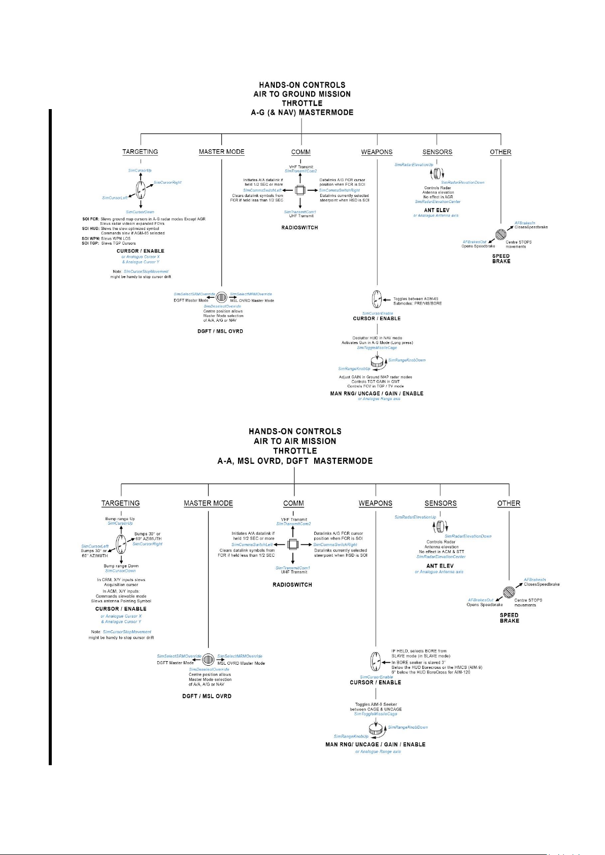
T.O. BMS1F-16CM-1 BMS 4.34 Change 2.00
BMS 4.34 Dash 1
© Red Dog 2012-2019 Page: 30
Page 31
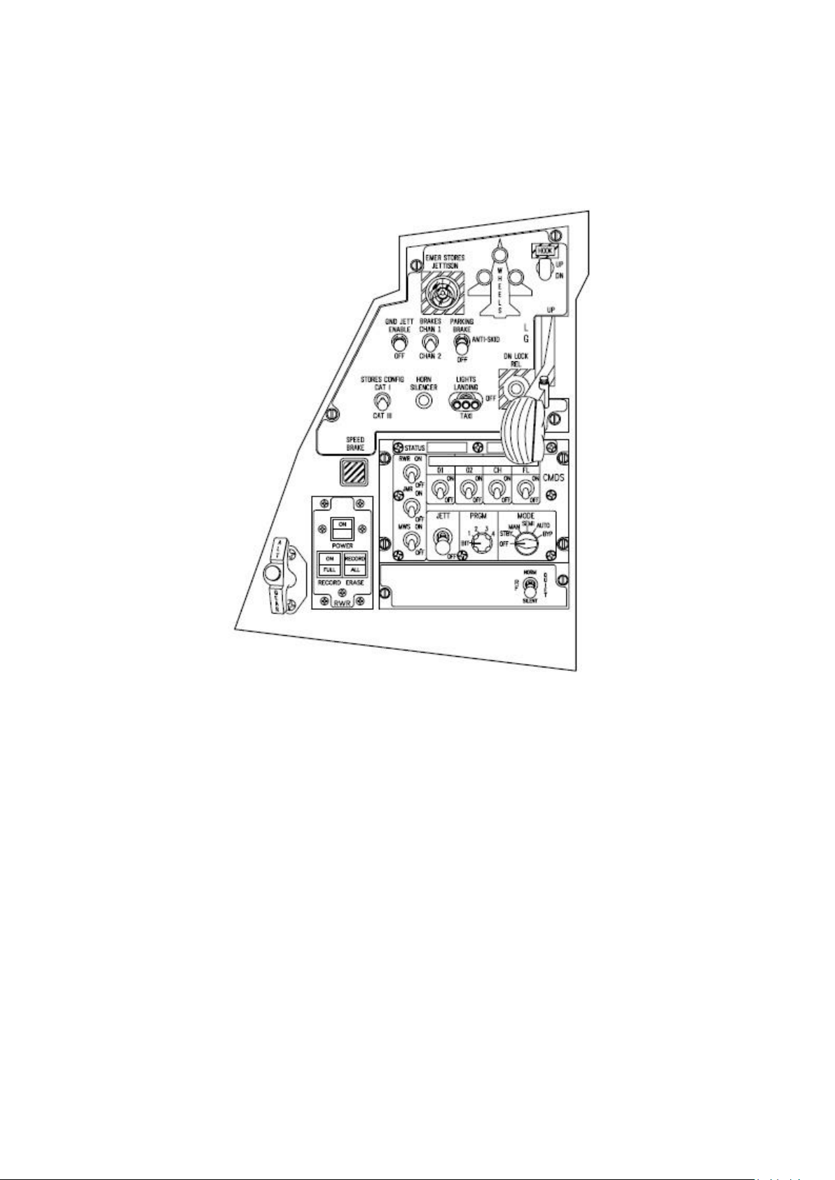
T.O. BMS1F-16CM-1 BMS 4.34 Change 2.00
BMS 4.34 Dash 1
© Red Dog 2012-2019 Page: 31
1.2.2. LEFT AUXILIARY CONSOLE
Page 32
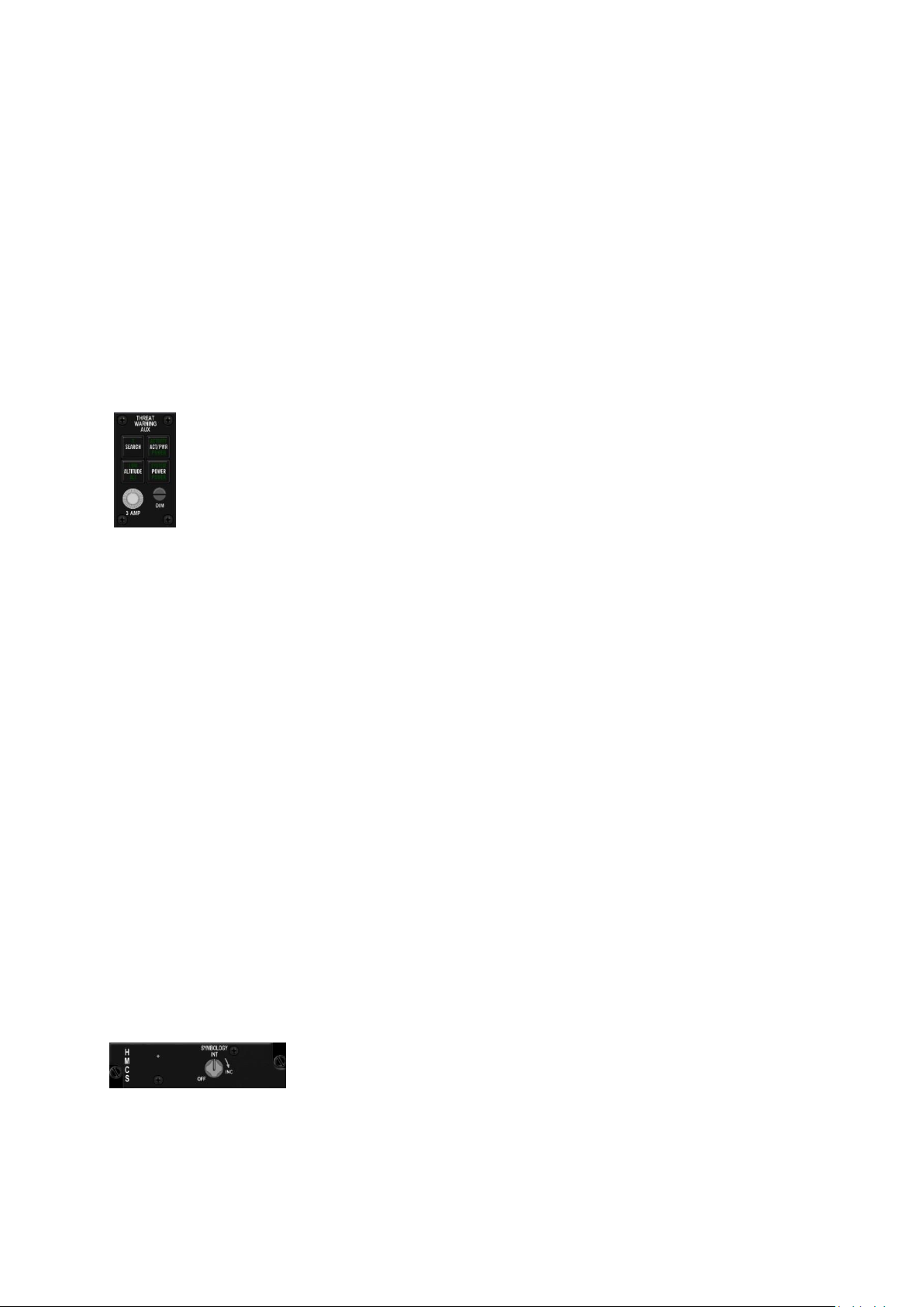
T.O. BMS1F-16CM-1 BMS 4.34 Change 2.00
BMS 4.34 Dash 1
© Red Dog 2012-2019 Page: 32
1.2.2.1 ALT GEAR HANDLE
This handle is used to extend the landing gear when normal extension is not possible (in case of
hydraulic failure due to engine flameout for instance). Pulling the handle provides enough pneumatic
pressure to open the gear doors and extend the landing gear. Please note you can lower the gear
with the alternate handle only once as the pneumatic pressure cannot be recharged in flight.
The ALT GEAR RESET button (white button in the centre of the handle) allows retraction of the
landing gear after an alternate extension if hydraulic pressure is available.
BMS Key Callbacks for the ALG GEAR handle
AFAlternateGear
AFAlternateGearReset
1.2.2.2 TWA panel
The Threat Warning Aux panel is part of the EWS suite. It is made up of 4 indicators (3 with
pushbuttons): SEARCH, ACT/PWR, ALTITUDE & POWER.
The POWER button applies and removes power to the EWS suite. The green indicator
comes on when the EWS is powered.
The ACT/PWR button is a dual indicator and has no button. The top indicator labelled ACTIVITY
comes on if the EWS is powered and detects a radar painting the aircraft.
The bottom indicator labelled POWER is on whenever the EWS suite is powered.
The SEARCH button allows ‘S’ search radar symbols to be displayed on the RWR display if the EWS
is powered and detects a search radar; by default they are not. With SEARCH enabled a SAM radar in
search mode will display as an ‘S’, well before you would expect to see its acquisition symbol if
SEARCH was not enabled, giving you an early warning in most cases.
With the SEARCH option not active the green ‘S’ indicator on the TWA will blink at 4 Hz whenever the
EWS detects a search radar painting the aircraft. In that configuration ‘S’ symbols are not displayed on
the RWR.
The green ‘S’ indicator on the TWA will remain lit as long as the SEARCH option is active. A further
press of the button deactivates the SEARCH option.
ALTITUDE is both a pushbutton and a dual indicator.
The pushbutton toggles between HIGH & LOW altitude threat assessment biasing. The EWS is able to
categorize the SAM threat according to their lethality at low or high altitude.
The top indicator labelled LOW comes on if the EWS is powered when the LOW option is selected.
The bottom indicator labelled ALT comes on whenever the EWS suite is powered.
BMS Key Callbacks for the TWA panel:
SimRwrPower (toggle)
SimRwrPowerOn
SimRwrPowerOff
SimRWRSetGroundPriority
SimRWRSetSearch
1.2.2.3 HMCS panel
The Helmet Mounted Cueing System displays weapon, sensor and flight
information to the pilot through the helmet visor providing off-boresight
missile capability. It is an extension of the HUD and considered as one
SOI (HUD & HMCS).
The panel bears a single knob featuring and ON/OFF switch and a clockwise motion for increased
brightness. The knob can be interfaced with an analogue device as well.
Refer to the HMCS section for further discussion of the HMCS.
Page 33
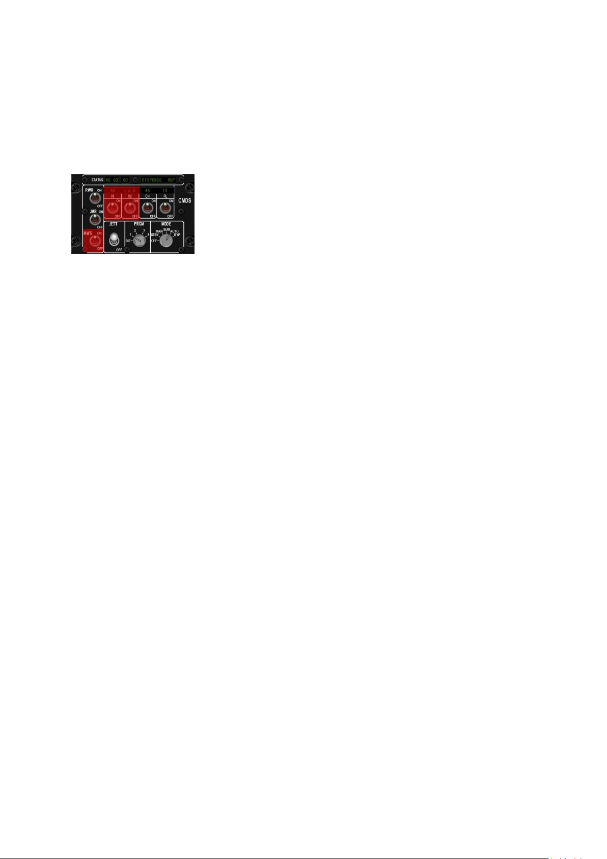
T.O. BMS1F-16CM-1 BMS 4.34 Change 2.00
BMS 4.34 Dash 1
© Red Dog 2012-2019 Page: 33
BMS Key Callbacks for the HMCS panel:
SimHmsSymWheelUp
SimHmsSymWheelDn
SimHmsOn
SimHmsOff
1.2.2.4 CMDS panel
The CMDS panel is part of the EWS suite and mainly manages all
countermeasures. It is used in conjunction with the CMS switch on the
sidestick (see stick section on the right console).
The RWR and JMR switches are two state toggle switches that control
automatic dispensing of chaff and flares. The RWR switch must be ON
for the SEMI and AUTO modes to function. The JMR switch needs to be
ON for the EWS to be able to release countermeasures coordinated with
the use of the Jammer pod.
The MWS switch is not implemented in the USAF latest block inventory jets and this is therefore not
implemented in BMS.
The panel provides four categories of expendables, only two are supported in the F-16. They are on
the right side of the panel and labelled CH for chaff and FL for flares. Category 01 & 02 are not
implemented and can remain OFF. When the switch is OFF the display above remains blank.
Needless to say both the CH and FL switches need to be ON for chaff and flares to be released. The
above indicator displays the number of expendables remaining and when bingo level is reached (set
through the DTC or UFC) LO is displayed with the number remaining. When a category is exhausted 0
is displayed.
The MODE knob selects the CMDS operating mode: OFF, STBY, MAN, SEMI, AUTO and BYP.
Depending on the mode selected the countermeasures released correspond to the selected program
(position of the PRGM knob).
OFF - the CMDS is not powered and countermeasures cannot be released.
STBY - the release parameters and programming can be manually changed using the UFC. It is the
only mode allowing reprogramming. The CMDS cannot release countermeasures in this mode.
MAN - only programs 1 to 5 can be released manually by the pilot by using the CMS on the sidestick.
CMS forward releases whatever program is selected (1 to 4) through the PRGM knob. Program 5 can
also be released with the slap switch on the left side panel.
SEMI - release is not automatic but the EWS will prompt the pilot through the VMS (“COUNTER”)
whenever the system feels countermeasures should be employed. The pilot then can give consent to
release by depressing CMS aft. The selected program will be then released once. If the threat persists
the EWS will prompt for consent again (“COUNTER”). Consent must be given each time. Please note
that for the SEMI mode to work the RWR switch on the CMDS panel needs to be ON.
AUTO - Consent must be given once (CMS aft) and is assumed until it is explicitly cancelled with a
CMS right. Deployment of countermeasures is thus automatic and can deplete your stores very fast
depending on the program selected.
BYP - is a Bypass mode and is used when the CMDS fails. BYP allows the pilot to release one chaff &
one flare only at each CMS forward command. BYP is always manual; no SEMI or AUTO functions
are active while in BYP.
The PRGM knob allows the pilot to select one of the 4 pre-programmed countermeasure sequences.
When CMS forward is depressed the selected program is activated. There are a total of 6 programs
but only 1 – 4 can be selected through the PRGM knob. PRG 5 is always activated by the slap switch
on the left sidewall and PRG 6 is always activated by depressing CMS left. All 6 programs can be
programmed through DTC, or the UFC whenever the CMDS mode in is STBY.
The BIT position is the CMDS self-test and is not implemented in BMS.
Page 34

T.O. BMS1F-16CM-1 BMS 4.34 Change 2.00
BMS 4.34 Dash 1
© Red Dog 2012-2019 Page: 34
The JETT switch dumps all remaining flares at once (no visual effect implemented).
The top row indicators simply provide GO, NO GO, DISPENSE RDY messages.
GO means all system are in the green and the CMDS is ready.
NO GO means the system is not ready (one of the systems is not powered or has failed).
DISPENSE RDY comes ON whenever the CMDS is ready to dispense but consent is required.
BMS Key Callbacks for the CMDS panel:
SimEWSRWROn
SimEWSRWROff
SimEWSRWRPower (toggle)
SimEWSJammerOn
SimEWSJammerOff
SimEWSJammerPower (toggle)
SimEWSMwsOn
SimEWSMwsOff
SimEWSMwsPower (toggle)
SimEWSChaffOn
SimEWSChaffOff
SimEWSChaffPower (toggle)
SimEWSFlareOn
SimEWSFlareOff
SimEWSFlarePower (toggle)
SimEWSO1On
SimEWSO1Off
SimEWSO1Power (toggle)
SimEWSO2On
SimEWSO2Off
SimEWSO2Power (toggle)
SimEWSModeOff
SimEWSModeStby
SimEWSModeMan
SimEWSModeSemi
SimEWSModeAuto
SimEWSModeByp
SimEWSPGMInc
SimEWSPGMDec
SimEWSProgOne
SimEWSProgTwo
SimEWSProgThree
SimEWSProgFour
SimEWSProgDec
SimEWSProgInc
SimEwsJett (toggle)
SimEwsJettOff
SimEwsJettOn
1.2.2.5 Speedbrake indicator
A square mechanical indicator reports the speedbrake position to the pilot. Speedbrakes are activated
with the speedbrake switch on the throttle. Switch backwards extends the speedbrakes (momentarily)
and switch forwards closes the speedbrakes. The speedbrakes stop their motion once the switch is
replaced in the centre. The indicator with 9 dots indicates a speedbrake OPEN and when it’s closed
the indicator displays CLOSED. Diagonal lines signify lack of power to the indicator.
Page 35
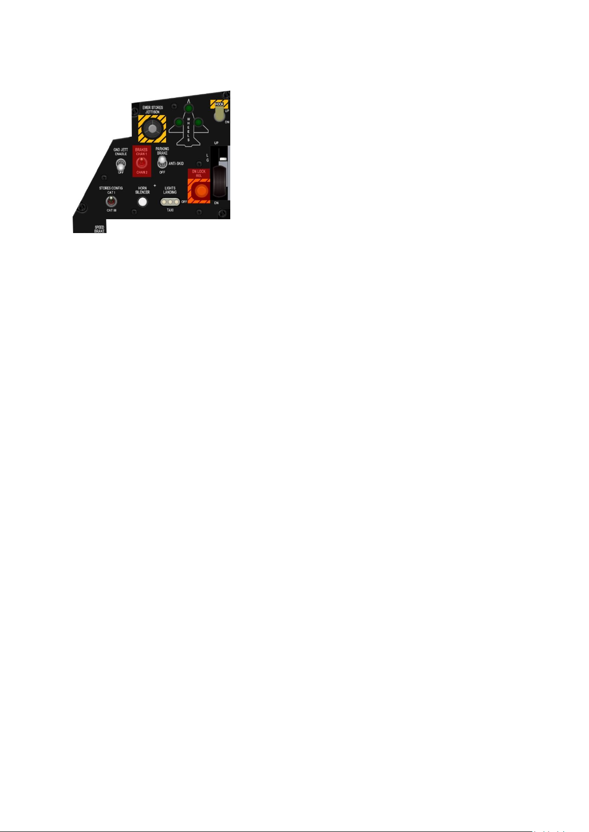
T.O. BMS1F-16CM-1 BMS 4.34 Change 2.00
BMS 4.34 Dash 1
© Red Dog 2012-2019 Page: 35
1.2.2.6 Gear panel
The landing gear (LG) and its doors are operated by hydraulic
system B. It has two main gears (MLG) and one nosewheel
(NLG).
The gear handle commands LG retraction or extension. A red
warning light in the top of the handle illuminates when the LG
and doors are in transit or have failed to lock in position. The
light also comes on below 10000 feet when all LG are not down
and locked, airspeed is less than 190 knots and rate of descent
is greater than 250 feet per minute.
In real aircraft the handle is locked in the up position to prevent
inadvertent lowering of the gear. To lower the gear the pilot has to depress the white pushbutton
located on the landing gear handle. This is not implemented in BMS.
The DN LOCK REL button is not implemented either in BMS. In the real jet it allows the pilot to retract
the LG on the ground by depressing this yellow button and moving the LG handle up. Indeed once
WOW is activated, the landing gear cannot be retracted unless this safety button is depressed.
What is implemented though is the WOW switch (Weight On Wheels). Once weight is on the gear
struts the WOW switch is activated allowing or terminating various system functions.
The three green wheels down indicators come on whenever the respective landing gear is down and
locked. A full gear down and locked indication is given when all three lights are green and the red
lollipop handle light is off.
The hook shaped switch above the LG handle is a two-position toggle switch operating the
emergency arrestment system. While it is implemented on the BMS F-16 there is unfortunately no
arrestment gear on any Falcon airbase yet, so it can currently be considered procedural only.
When the hook is down the HOOK caution light located on the caution panel (right aux) is illuminated.
The LIGHTS LANDING/TAXI light also has a specific shaped cap and operates the landing/taxi lights.
The real jet has a three-position switch because of the distinction made between the landing light and
the taxi light. In BMS we have no such distinction and the switch is a two-position toggle: up for light
on and down for off. Please note: the Per-Pixel Lighting option (on by default in Hardware > Shaders
> Lighting Effects) must be checked in Falcon BMS.cfg for the lights to be correctly visible.
The HORN SILENCER white pushbutton when depressed silences the VMS low speed/gear horn.
The horn becomes audible when the following conditions are met: below 10000ft, less than 190 knots,
gear not down and locked, sink rate greater than 250 fpm.
The STORES CONFIG CATI/CATIII switch is a two-position toggle switch: CATI and CATIII. CATIII
position should be selected when the aircraft is configured with a category III loading; AOA limiter is
then provided. Please refer to the FLCS chapter for further discussion.
The GND JETT switch is a two-position toggle switch: ENABLE and OFF. In ENABLE it allows the
pilot to jettison his load on the ground. Obviously in OFF this jettison is not possible.
The BRAKES channel switch is not implemented in BMS. We only have one channel brake and
aircraft braking is provided by the toebrakes. For those not having 3-axis rudder pedals the toebrakes
can also be implemented with a keystroke. It is strongly advised to use toebrake pedals in BMS as
differential braking is implemented. Please refer to the brakes chapter for further discussion about the
F-16 braking system.
The PARKING BRAKE switch is a magnetically held switch. In the real jet it has three positions but
the ANTI-SKID functionality is not implemented in BMS and thus it is a two-position switch in the BMS
cockpit.
Page 36

T.O. BMS1F-16CM-1 BMS 4.34 Change 2.00
BMS 4.34 Dash 1
© Red Dog 2012-2019 Page: 36
The parking brake when engaged holds the aircraft stationary without the use of wheel brakes.
Considering that a lightly loaded jet in BMS can move at idle power it is important to use parking
brakes to relieve the wheel brakes and their tendency to develop heat which decreases performance
and may present hazardous situations.
In the real jet the parking brakes are automatically de-energised when the throttle handle moves one
inch past the idle point. In BMS the parking brakes disengage automatically (that’s why it is a
magnetic switch) above 80% RPM. There is no parking brake status indicator aside from the position
of the switch.
The EMER STORES JETTISON when depressed for more than 1 second jettisons all A-G stores and
external fuel tanks. A-A weapons and any HTS, TGP and ECM pods remain on board. While the
emergency jettison is depressed the MFD displays the SMS Jettison page.
BMS Key Callbacks for the GEAR panel
SimGndJettOn
SimGndJettOff
SimGndJettEnable (toggle)
SimCATI
SimCATIII
SimCATSwitch (toggle)
SimSilenceHorn
SimLandingLightOn
SimLandingLightOff
SimLandingLightToggle
SimParkingBrakeOn
SimParkingBrakeOff
SimParkingBrakeToggle
AFGearUp
AFGearDown
AFGearToggle
SimEmergencyJettison
SimHookUp
SimHookDown
SimHookToggle
Page 37
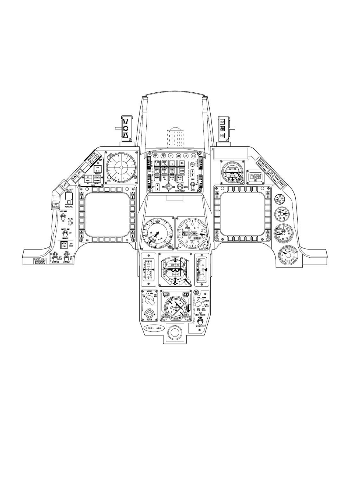
T.O. BMS1F-16CM-1 BMS 4.34 Change 2.00
BMS 4.34 Dash 1
© Red Dog 2012-2019 Page: 37
1.2.3. CENTRE CONSOLE
Page 38
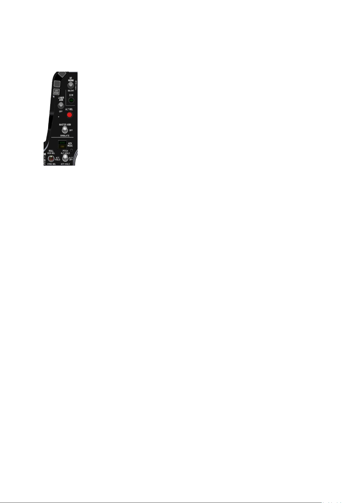
T.O. BMS1F-16CM-1 BMS 4.34 Change 2.00
BMS 4.34 Dash 1
© Red Dog 2012-2019 Page: 38
1.2.3.1 MISC panel
The MISC panel may be different from one aircraft to another. BMS uses the Block
50/52 MISC panel featuring Autopilot, TFR, MASTER ARM, Laser, and RF switches.
The two lower Autopilot switches are the ROLL switch (left) and the PITCH switch
(right). Both are three-position switches.
The PITCH switch is the master switch and is magnetically held in either the ALT
HOLD or ATT HOLD position. Both engage Pitch and Roll autopilot. Roll depends on
the ROLL switch position. The centre position A/P OFF disengages the autopilot.
ALT HOLD - the autopilot will strive to maintain the altitude determined by the INS at
the time the PITCH mode switch was set.
ATT HOLD - the autopilot will strive to maintain the attitude/pitch determined by the
INS at the time the PITCH mode switch was set.
The ROLL switch is functional only when the PITCH switch is engaged in ALT HOLD
or ATT HOLD. When the PITCH switch is centred in A/P OFF the ROLL switch is inoperative.
The HDG SEL position turns the aircraft to capture and maintain the heading selected by the heading
marker on the HSI.
In ATT HOLD the autopilot maintains ROLL attitude by INS at the moment the ROLL switch was set.
In STRG SEL the autopilot steers the aircraft to the selected steerpoint.
The autopilot can be engaged only if all the following conditions are met:
• Gear up,
• Air refuelling door closed,
• No FLCS fault present,
• AOA must be less than 15°,
• DBU not engaged,
• MPO switch not in OVRD,
• ALT FLAPS not in EXTEND,
• TRIM/AP DISC switch not in DISC,
• Stall Horn is silent.
When the autopilot is engaged and any of the above conditions are no longer met the autopilot
disconnects automatically. The PITCH switch then snaps back to the A/P OFF position and a WARN
message is displayed in the HUD.
The pilot can override the autopilot by depressing the stick paddle lever. While keeping the lever
depressed he can change PITCH and ROLL input. Upon releasing the paddle the AP will re-engage
in the mode it was set. If the autopilot is in ATT HOLD there is no need to press the paddle, a new
reference is now taken in ATT AP when stick is moved and released.
Note that the Stick TRIM buttons are inoperative when the autopilot is engaged.
For further information about the autopilot system refer to the autopilot chapter later in this manual.
The ADV mode pushbutton indicator is used with the Terrain Following Radar (TFR) system which is
set through the TFR MFD page. The indicator has a pushbutton that turns AUTO TFR on/off. The top
part of the indicator is labelled ACTIVE in green and illuminates when AUTO TFR is enabled. The
lower part of the indicator is labelled STBY in yellow and indicates that the TFR system is in STBY
(manual mode or blended mode). Automatic TFR is only available if you are carrying the AN/AAQ-13
navigation pod (NVP).
The MASTER ARM switch is a three-position toggle switch labelled ARM, OFF and SIM.
The ALT REL is a pushbutton that works exactly like the pickle button on the HOTAS SSC/stick.
Page 39

T.O. BMS1F-16CM-1 BMS 4.34 Change 2.00
BMS 4.34 Dash 1
© Red Dog 2012-2019 Page: 39
The LASER ARM switch is a two-position toggle switch. In ARM it enables the targeting pod laser. The
laser needs to be fired to allow Laser Guided Bombs to guide on its reflected energy. The laser can be
fired manually (stick trigger first detent) or automatically a few seconds before impact. Placing the
switch in ARM doesn’t fire the laser, it readies the system so the laser can be fired depending on the
settings in the LASER DED page (LIST 0 0 5).
The RF switch is a three-position toggle switch and controls electromagnetic emissions from the
aircraft as follows:
NORM is the default position and is used for normal operation of the aircraft.
QUIET reduces the level of EW emissions by turning the radar and IFF transponder to standby.
SILENT shuts down all EW emissions from the aircraft: RADAR, TFR, RALT, ECM, IFF.
BMS Key Callbacks for the MISC panel:
SimLaserArmToggle
SimLaserArmOn
SimLaserArmOff
SimRightAPSwitch
SimLeftAPSwitch
SimLeftAPUp
SimLeftAPMid
SimLeftAPDown
SimLeftAPInc
SimLeftAPDec
SimRightAPUp
SimRightAPMid
SimRightAPDown
SimRightAPInc
SimRightAPDec
AFDragChute
SimToggleTFR
SimStepMasterArm
SimArmMasterArm
SimSafeMasterArm
SimSimMasterArm
SimMasterArmDown
SimMasterArmUp
SimPickle
SimRFSwitch
SimRFSwitchUp
SimRFSwitchDown
SimRFNorm
SimRFQuiet
SimRFSilent
1.2.3.2 Left EYEBROW
The left eyebrow is made of a stack of pushbuttons and a stack of lights. Only
one pushbutton is implemented: F-ACK.
Depressing F-ACK acknowledges or recalls faults on the PFL display on the
right AUX console (see RIGHT AUX section below).
The IFF IDENT pushbutton is not currently implemented although we now
have a fully implemented IFF system in BMS.
The lights are made up of a red warning light for the TFR system that comes
on when TFR fails and the very important amber MASTER CAUTION light.
This light comes on (with a slight delay) when the system detects a fault or
failure. The light is coupled with a pushbutton that allows it to be reset once the fault is acknowledged
or solved. It is of paramount importance to understand that the proper way to extinguish the MASTER
CAUTION light is not to reset it but to clear the fault that caused it to light up.
Example: during flight you are CAT III and you jettison your load. The system senses the change but
the pilot has to manually switch to CAT I, else the jet will still be limited to CAT III. The STORES
CONFIG and the MASTER CAUTION lights come on. Obviously resetting MASTER CAUTION would
extinguish it, but the STORES CONFIG PFL light would stay on and the fault wouldn’t be cleared. The
Page 40
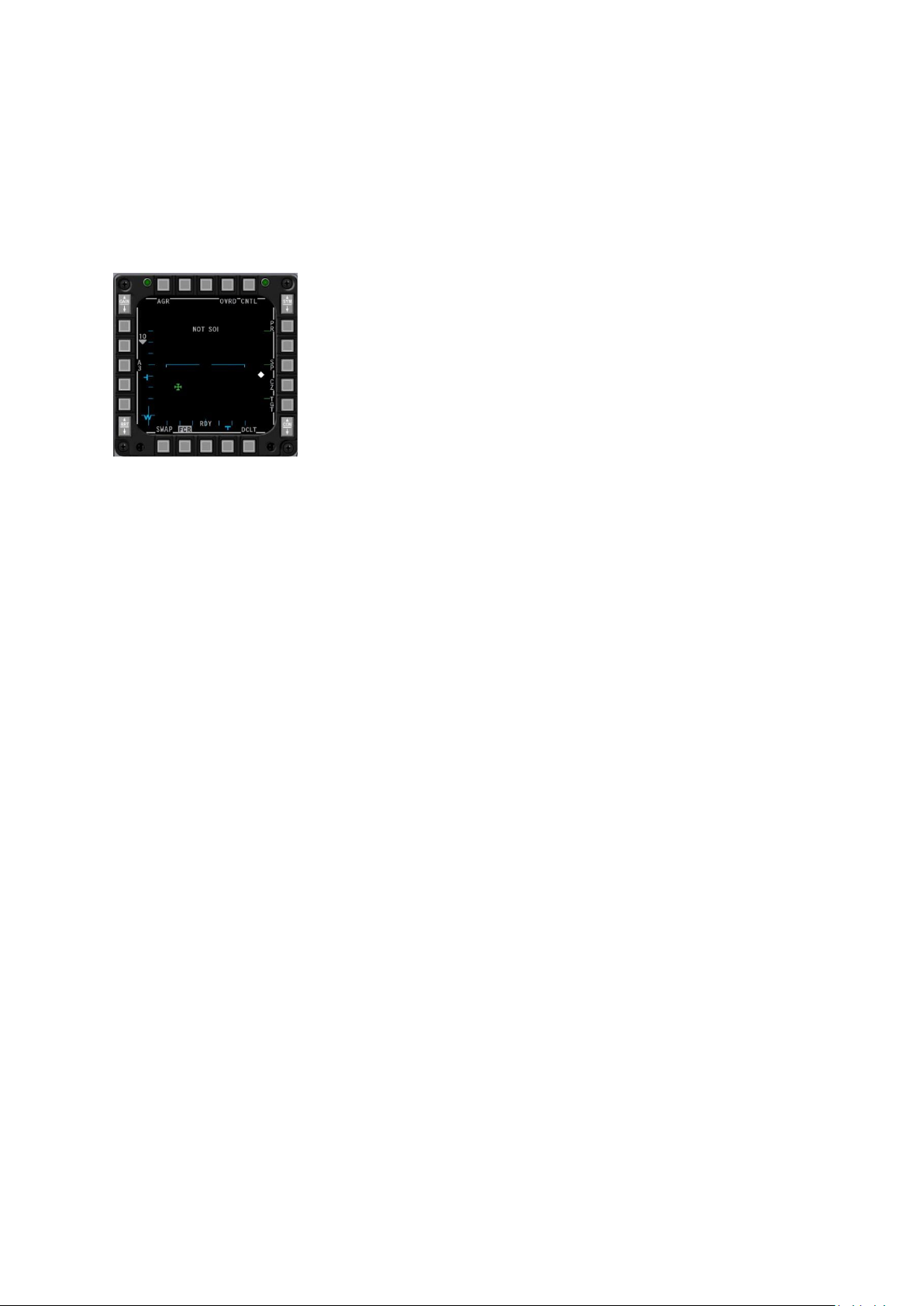
T.O. BMS1F-16CM-1 BMS 4.34 Change 2.00
BMS 4.34 Dash 1
© Red Dog 2012-2019 Page: 40
pilot by switching the CAT switch to CAT I clears the fault, which extinguishes the STORES CONFIG
and MASTER CAUTION lights.
BMS Key Callbacks for the LEFT eyebrow:
SimICPFAck
ExtinguishMasterCaution
1.2.3.3 Left MFD & Right MFD
Both MFDS are main displays giving invaluable information to the pilot.
They each have 20 pushbuttons and four 2 position rockers in each
corner. Out of those 4 only two are implemented: the Brightness and
Gain rockers on the left of the MFD.
The 20 pushbuttons arranged in 4 rows of 5 are called OSBs (Option
Selection Buttons) and labelled from 1 to 20 starting at the left button on
the top row and going in a clockwise direction. The top row is thus made
up of OSB #1 to OSB #5.
The displays have many different pages and subpages, which are explained later in the MFD chapter.
As such the function of each button changes according to the active page and is always displayed
just next to the button.
BMS Key Callbacks for the LEFT& RIGHT MFDs:
SimCBEOSB_1L SimCBEOSB_1R
SimCBEOSB_2L SimCBEOSB_2R
SimCBEOSB_3L SimCBEOSB_3R
SimCBEOSB_4L SimCBEOSB_4R
SimCBEOSB_5L SimCBEOSB_5R
SimCBEOSB_6L SimCBEOSB_6R
SimCBEOSB_7L SimCBEOSB_7R
SimCBEOSB_8L SimCBEOSB_8R
SimCBEOSB_9L SimCBEOSB_9R
SimCBEOSB_10L SimCBEOSB_10R
SimCBEOSB_11L SimCBEOSB_11R
SimCBEOSB_12L SimCBEOSB_12R
SimCBEOSB_13L SimCBEOSB_13R
SimCBEOSB_14L SimCBEOSB_14R
SimCBEOSB_15L SimCBEOSB_15R
SimCBEOSB_16L SimCBEOSB_16R
SimCBEOSB_17L SimCBEOSB_17R
SimCBEOSB_18L SimCBEOSB_18R
SimCBEOSB_19L SimCBEOSB_19R
SimCBEOSB_20L SimCBEOSB_20R
SimCBEOSB_BRTUP_L SimCBEOSB_BRTUP_R
SimCBEOSB_BRTDOWN_L SimCBEOSB_BRTDOWN_R
SimRadarGainUp
SimRadarGainDown
Page 41
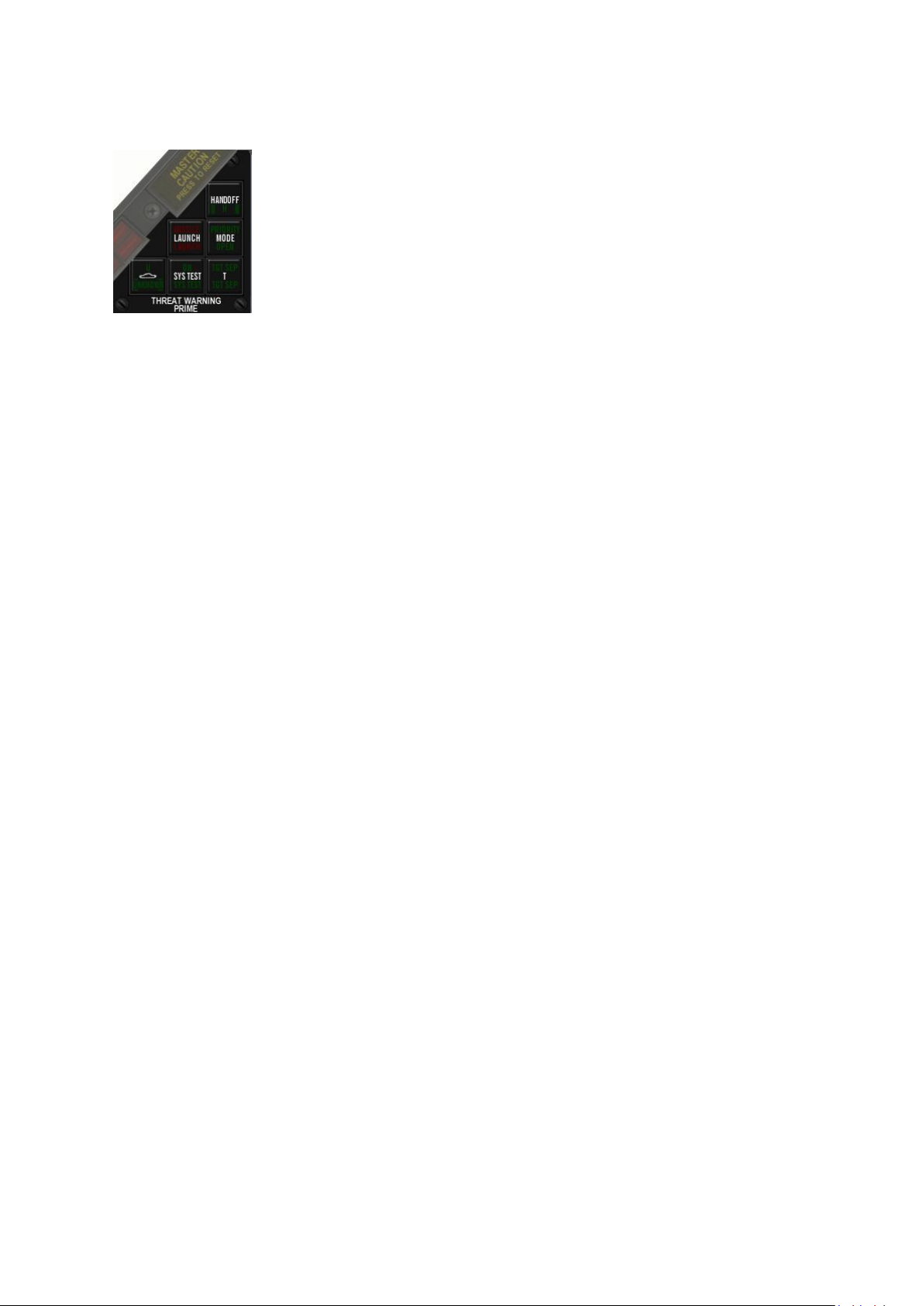
T.O. BMS1F-16CM-1 BMS 4.34 Change 2.00
BMS 4.34 Dash 1
© Red Dog 2012-2019 Page: 41
1.2.3.4 TWP panel
The Threat Warning Prime panel is located right next to the RWR (Radar
Warning Receiver) display and manages the information displayed on the ALR56 RWR. The TWP is made of 6 square lights all featuring a push button.
Each indicator has multiple lights (top and bottom) the bottom light comes on
when the system is powered and the top light comes on depending on the
status of the relevant system, except for the Missile LAUNCH indicator.
Here is a rundown of each indicator/ button:
• HANDOFF - used to set the mode of operation of the RWR. The 4 modes are: Normal,
Diamond Float, Transient and Latch. These modes will be explained in more detail in the
Electronic Warfare System section of this manual. For now you should simply know that the
mode giving the best Situational Awareness is the Diamond Float mode where the diamond
floats to the highest priority symbol. That mode is entered with a short push (less than one
second) on the HANDOFF button.
The bottom light of the indicator is on as soon as there is power and the top indicator comes
on only when a handoff mode is engaged (Diamond Float, Transient, Latch).
• LAUNCH - this indicator flashes at 4Hz as soon as the EWS (Electronic Warfare System)
detects a radar missile launched at ownship. The indicator is backed up by audible warning
tones. The indicator features a pushbutton to test the launch warning. Press the button to
check the audio tone and indicator light.
• PRIORITY (MODE) - enables some declutter of the RWR display by displaying only the 5
most important symbols instead of the usual 12 symbols (16 when UNKNOWN mode is
selected). When the priority MODE button is depressed the RWR enters PRIORITY mode,
the top light comes on and the bottom light OPEN goes off, as both lights are mutually
exclusive.
When PRIORITY mode is enabled the top PRIORITY light will flash if the EWS detects more
than 5 threat emitters.
The RWR remains in this mode until the pilot exits PRIORITY MODE by depressing the
button again. At that time the top light extinguishes and the bottom OPEN light illuminates.
• UNKNOWN (SHIP SYMBOL) - When depressed the top (U) light illuminates and the RWR
displays U symbols (unknown radar). It can then also display 16 symbols instead of the usual
12. The pilot can deselect this mode by depressing the pushbutton again. The top light then
extinguishes.
• SYS TEST – The bottom light of the indicator will be on whenever the EWS is powered. The
top light will come on whenever the system test is running. Depressing the push button will
initiate the test sequence that will run for a few seconds. During that time all TWP lights and
modes will be tested. Some alphanumeric codes will also be displayed on the RWR.
• TGT SEP (T) - Depress this indicator when you want to have a better view of two emitters
which are close to each other. When depressed the top TGT SEP light illuminates and the
symbols on the RWR are spread out for 5 seconds. After that time the RWR reverts to
normal and the top light extinguishes. The bottom light is on as soon as power is applied.
BMS Key Callbacks for the TWP:
SimRWRSetPriority
SimRWRSetTargetSep
SimRWRSetUnknowns
SimRWRSetNaval deleted
SimRWRHandoff
SimRWRLaunch
SimRWRSysTest
Page 42
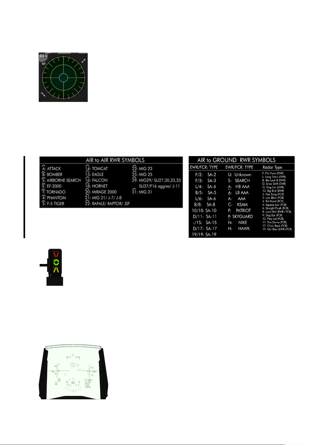
T.O. BMS1F-16CM-1 BMS 4.34 Change 2.00
BMS 4.34 Dash 1
© Red Dog 2012-2019 Page: 42
1.2.3.5 ALR-56 RWR
The ALR-56 RWR displays threat emitters depending on their azimuth relative
to your aircraft. It does not give distance information. The display is made of
two concentric circles: inner and outer. The threats are categorised by order of
importance; the more lethal threats are placed in the inner circle, while the
secondary threats are left in the outer.
The RWR scope also consists of four noise bars located around the centre
circle at 6, 9, 12 and 3 o’clock. They indicate the status of noise in the bands 0,
1, 2, and 3 respectively; however this is not implemented and is graphical only.
There is a cycle timer on the left end of the band 3 noise bar. This is a vertical bar that moves up and
down. As the RWR becomes saturated with signal activity the cycle timer moves progressively slower.
With no signal activity, it moves up and down once per second. With full RWR activity it moves up and
down every 2.6 seconds.
The symbols displayed on the RWR depend on their radar type, as seen below. Airborne symbols are
displayed with an inverted V on top of them to differentiate them from the ground emitters. Other
RWRs may be installed in other F-16s. For further information refer to the TO-BMS1F-16CM-34-1-1.
BMS Key Callbacks for the RWR:
SimRWRBrightnessUp
SimRWRBrightnessDown
1.2.3.6 Left INDEXER
The left indexer is made of three lights relevant to the Angle of Attack and is located to
the left of the HUD. It is a repeater of the AOA instrument on the centre console and the
HUD AOA tape.
The AOA is sensed by two conical sensors on each side of the nose of the F-16. AOA
indication is valid for two point landing.
The top light points down and comes on when the AOA is above 14° (on speed AOA too slow).
The centre light featuring a green doughnut comes on if the AOA is between 11 and 14° (13° = on
speed AOA for landing).
The bottom light points up and comes on when the AOA is below 11° (on speed AOA too fast for
approach).
These lights are always on even when the gear is retracted, allowing the pilot to quickly check his
AOA in every flight situation.
1.2.3.7 HUD
The HUD (Heads Up Display) displays a variety of flight information
through a collimating system. A more in depth explanation of the HUD
can be found in the relevant chapter later in this manual. The HUD is
powered on using the SYM wheel on the left of the ICP. That wheel
features a switch at the beginning of its course which toggles the HUD
on/off. Once the HUD is enabled the wheel adjusts HUD brightness.
Many settings on the HUD can be changed by the pilot through the
UFC or the HUD control panel on the right console (see right console
section).
Page 43
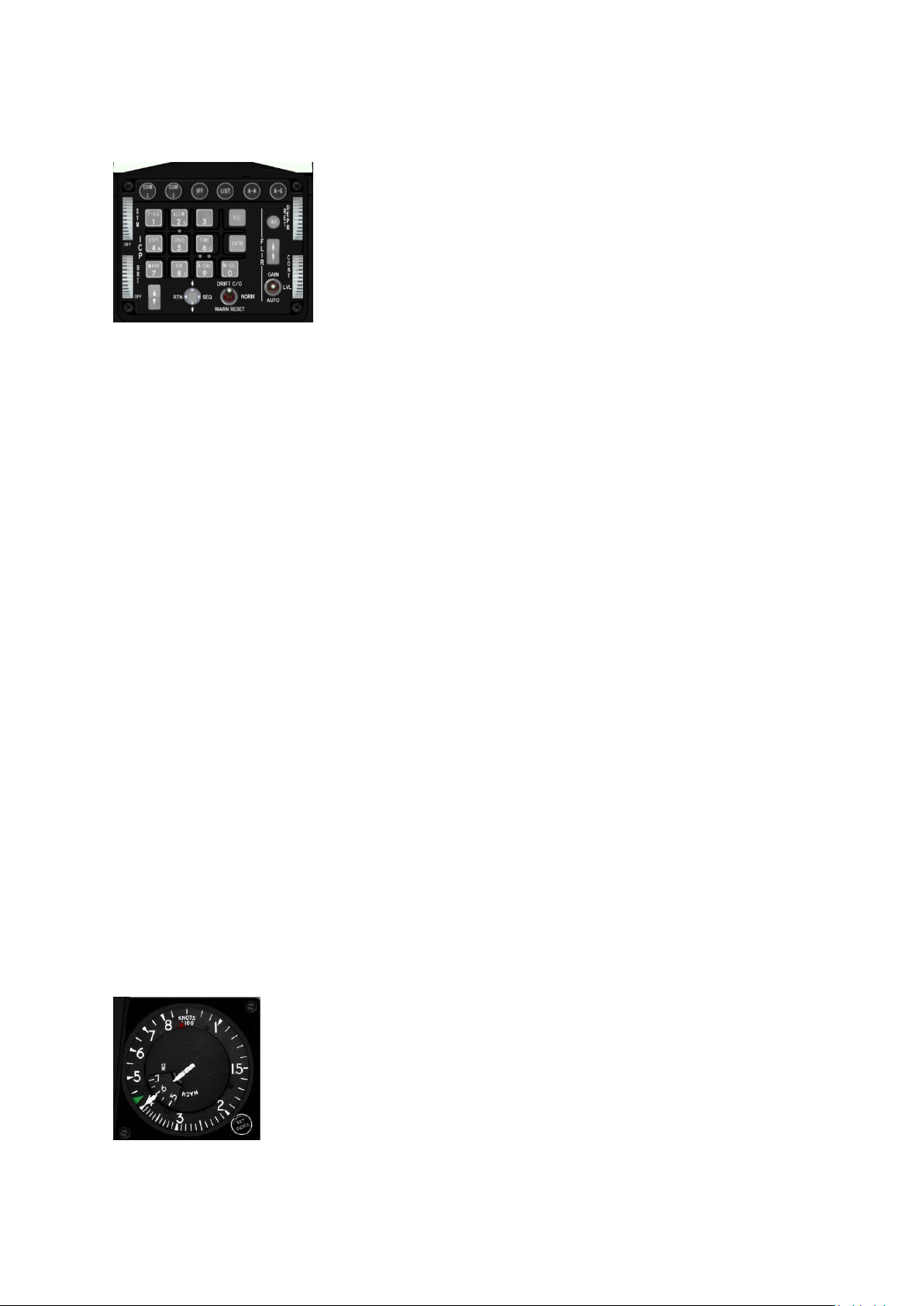
T.O. BMS1F-16CM-1 BMS 4.34 Change 2.00
BMS 4.34 Dash 1
© Red Dog 2012-2019 Page: 43
1.2.3.8 ICP & DED
The ICP (Integrated Control Panel) is the primary interface between
the pilot and the aircraft systems. It is part of the UFC (Up Front
Controller) made up of the ICP and the DED (Data Entry Display)
with the ICP as the keyboard and the DED as the display.
As a complicated system the UFC has its own chapter with detailed
information later in this manual.
BMS Key Callbacks for the ICP:
SimICPCom1
SimICPCom2
SimICPNav
SimICPAA
SimICPAG
SimICPIFF
SimICPLIST
SimICPTILS
SimICPALOW
SimICPTHREE
SimICPStpt
SimICPCrus
SimICPSIX
SimICPMark
SimICPEIGHT
SimICPNINE
SimICPZERO
SimICPCLEAR
SimICPEnter
SimICPPrevious
SimICPNext
SimICPResetDED
SimICPDEDUP
SimICPDEDDOWN
SimICPDEDSEQ
SimDriftCO
SimDriftCOOn
SimDriftCOOff
SimWarnReset
SimSetWX
SimFlirLevelUp
SimFlirLevelDown
SimBrtWheelUp
SimBrtWheelDn
SimSymWheelUp
SimSymWheelDn
SimHUDPower
SimHUDOn
SimHUDPOff
SimRetUp
SimRetDown
1.2.3.9 MACHMETER
The Mach meter is a primary flight instrument giving indicated airspeed in both
knots (nautical miles per hour) and Mach number. The indicated airspeed is
given by the outer needle on the scale from 60-80 to 800 knots and the Mach
number is given by the inner needle and the inner scale.
The Mach meter has two indicators: a red triangle illustrating the VNE (Velocity
Never Exceed) speed which cannot be set and the green triangle which is a
simple pilot selectable caret. It does not work in the 3D cockpit of BMS but
cockpit builders can have it implemented through the Mach meter knob when
using MFDE, a software tool that extracts instruments & displays.
It is used as a visual aid to maintain the assigned speed when flying IFR for instance.
Page 44
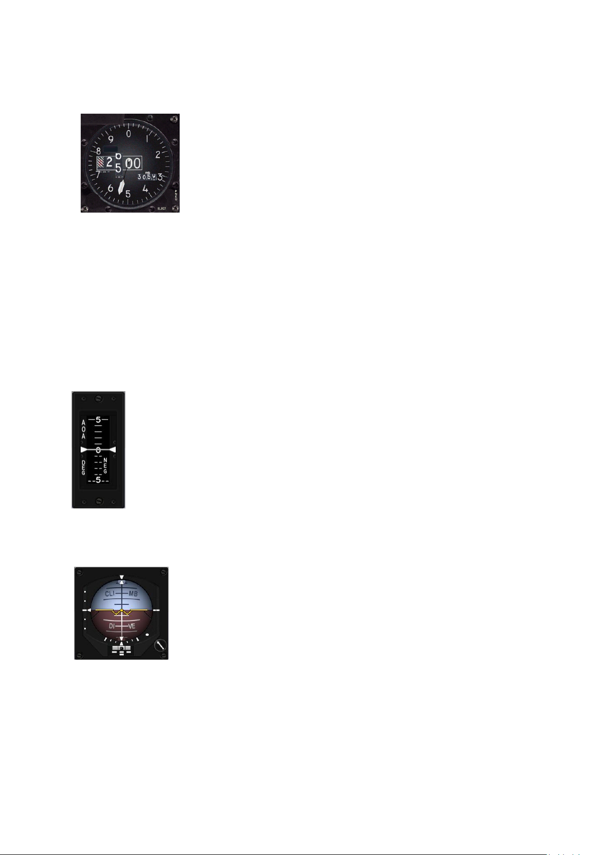
T.O. BMS1F-16CM-1 BMS 4.34 Change 2.00
BMS 4.34 Dash 1
© Red Dog 2012-2019 Page: 44
1.2.3.10 ALTIMETER
The altimeter gives altitude in feet. The needle reads from zero to one
thousand feet on the outer scale and the large instrument window gives
altitude rounded to the nearest hundred feet. To derive the current altitude,
use the drum number and needle in combination.
For the example shown left, the drum reads 2500 feet tending to 2600 feet
and the needle reads 540 feet, so in combination they show the present
aircraft altitude as 2540 feet on QNH 3059 in Hg.
The smaller window on the right allows the pilot to input the local altimeter setting in millibars
(HectoPascal) or in inches of mercury depending on the options set in Falcon BMS.cfg to compensate
the instrument for the current atmospheric conditions.
The pressure is changed through the altimeter knob on the bottom left of the instrument.
The instrument is flagged PNEU when it receives only pneumatic pressure and no electrical power. In
this case the instrument behaves as a standard pressure altimeter.
BMS Key Callbacks for the Altimeter:
SimAltPressInc
SimAltPressDec
SimAltPressIncBy1
SimAltPressDecBy1
1.2.3.11 AOA
The AOA indicator, located on the instrument panel, displays actual AOA in degrees.
The indicator has a vertically moving tape display indicating an operating range of -32° to
approximately +32°.
The tape is colour coded from 9° to 17° to coincide with the colour coded symbols on the
AOA indexer.
The instrument is flagged OFF when there is no power available.
1.2.3.12 ADI
The ADI (Attitude Direction Indicator) is the main attitude flight instrument and
gives ownship attitude along pitch, roll and yaw axis supplied by the EGI/INS.
The F-16 ADI is mainly used for IFR flying and also features an ILS localiser
and glideslope when the ILS modes are activated.
The knob on the bottom right of the instrument is not implemented in Falcon
BMS due to the fact that it is used in reality to centre the instrument along the
fixed horizontal reference (according to the seating position of the pilot).
The ADI also has 4 flags, one in each corner of the instrument: OFF, LOC, GS and AUX.
The red OFF flag is displayed when the instrument does not receive power or the INS has failed.
The red LOC flag is displayed when the LOCaliser needle is unreliable.
The red GS flag is displayed when the Glide Slope needle is unreliable.
The yellow AUX flag is displayed while the heading value of the INS is not reliable. During ramp starts
the AUX flag remains displayed until status 90, 60 seconds into the initial INS alignment. When the
heading value of the INS becomes reliable the flag disappears. In BMS that is your cue for a short
ramp start; as long as the GPS switch is on, the INS will remain fully reliable.
Page 45
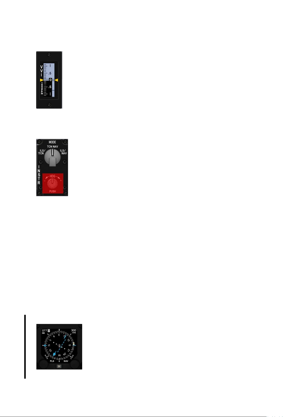
T.O. BMS1F-16CM-1 BMS 4.34 Change 2.00
BMS 4.34 Dash 1
© Red Dog 2012-2019 Page: 45
1.2.3.13 VVI
The VVI (Vertical Velocity Indicator) located on the instrument panel displays vertical
velocity in thousandths of feet per minute.
The instrument features a vertically moving tape indicating an operating range from 6000 to +6000 feet/min.
The instrument is flagged OFF when there is no power available.
1.2.3.14 INSTRUMENT MODE panel
This panel has been replaced by a blank panel in later blocks where the HSI has
been replaced with the EHSI. On the EHSI modes are changed with the M button.
The bottom knob is not implemented in BMS. In reality it is used to correct INS
heading deviation, which never happens currently in our sim. The top knob is a fourposition knob setting the instrument mode: ILS/TCN – TCN – NAV – NAV/ILS.
• ILS/TCN - one of the two modes used to display the ILS needles. It activates
the ILS symbology in the HUD, the ADI and the HSI. The course deviation indicator
on the HSI gives the localiser deviation. The TO/FROM indicator is not displayed and
the bearing pointer points at the active TACAN station. The range value in the DME
window of the HSI is from the active TACAN station and not the ILS.
• TCN - the HSI displays course deviation and distance from the active TACAN station. ILS
symbology is not displayed. All HSI indicators point to the TACAN station. The TO/FROM
indicator is displayed.
• NAV - the HSI displays course deviation and distance from the steerpoint of interest (active
UFC Steerpoint) and not the TACAN. The TO/FROM indicator is displayed.
• ILS/NAV - ILS symbology is displayed as in the other ILS mode in the HUD, ADI and HSI.
The course deviation indicator on the HSI gives the localiser deviation, the TO/FROM
indicator is not displayed, the range in the DME window is given to the steerpoint of interest
(and not the ILS) and the bearing pointer on the HSI points to the steerpoint of interest as
well.
BMS Key Callbacks for the INSTR MODE panel:
SimStepHSIMode
SimHSIIlsTcn
SimHSITcn
SimHSINav
SimHSIIlsNav
SimHSIModeInc
SimHSIModeDec
1.2.3.15 EHSI
Block 50 and Block 52(+) have been updated with the electronic version of the
Horizontal Situation Indicator. The EHSI is the primary flight instrument for
navigation. It features a top down view with your aircraft in the centre and a
compass rose all around it. Its use is fully explained in the BMS Comms and
Nav book that explains basic and advanced radio-navigation.
The instrument features two knobs and one M button on the bottom, the left
knob labelled HDG for Heading is used to set a heading caret on the compass
rose to a heading of your choice (as a visual cue).
The right knob labelled CRS for Course is used to enter a course value
manually which will be reflected on the course deviation indicator. That value is displayed on the top
Page 46
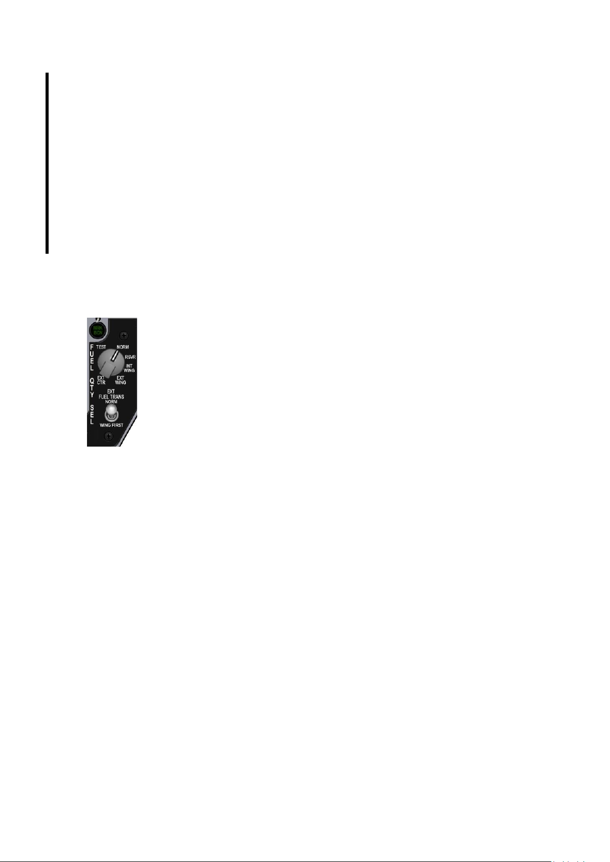
T.O. BMS1F-16CM-1 BMS 4.34 Change 2.00
BMS 4.34 Dash 1
© Red Dog 2012-2019 Page: 46
right window of the instrument. The top left window displays the range in Nautical miles to the
selected destination, according to the EHSI mode. Please note the DME is now displayed in tenths of
nautical miles. The M button toggles the available Mode. Available modes are TCN, PLS (Precision
Landing system = ILS) PLC/NAV & PLS/TCN.
The instrument is flagged with an OFF when no power is available.
For a full in-depth review of EHSI use please refer to the BMS-Comms-Nav-book in your Docs folder.
We cannot explain the EHSI without explaining radio navigation.
BMS Key Callbacks for the HSI:
SimStepHSIMode
SimHsiCourseInc
SimHsiCrsIncBy1
SimHsiCourseDec
SimHsiCrsDecBy1
SimHsiHeadingInc
SimHsiHdgIncBy1
SimHsiHeadingDec
SimHsiHdgDecBy1
1.2.3.16 FUEL QTY SEL panel
The Fuel Quantity panel is made of one 6-position knob and one 2-position switch.
The top knob controls the fuel quantity displayed on the fuel QTY gauge on the
RIGHT AUX console.
• TEST - AR & FR needles each point to 2000, the totalizer displays 6000 and
both fuel low caution lights illuminate on the caution panel (right AUX console).
• NORM - AL needle displays the quantity of fuel contained in the AFT (LEFT)
reservoir and A-1 fuselage tanks. FR needle displays the quantity of fuel contained in
the FORWARD (RIGHT) reservoir and F-1, F-2 fuselage tanks. The Totalizer displays
the total fuel on board.
The NORM position is the only position that enables the automatic forward fuel
transfer system, trapped fuel warning and BINGO fuel computation based on fuselage
fuel.
• RSVR - AL and FR needles point to fuel quantity left in the aft and forward reservoir tanks.
The Totalizer displays the total fuel on board.
• INT WING - AL needle points to the fuel quantity remaining in the left internal wing tank. FR
needle points to the fuel quantity remaining in the right internal wing tank. The Totalizer
displays the total fuel on board. Please note, the fuel contained in the internal wings does not
influence the fuel imbalance as they empty first into the fuselage tanks and the CG doesn’t
move as long as the fuselage tanks remain full.
• EXT WING - AL/FR needles point to the quantity of fuel left in the left and right external fuel
tanks. The Totalizer displays the total fuel on board.
• EXT CTR - AL needle points to zero. FR needle points to the quantity of fuel remaining in the
centre external tank. The Totalizer displays the total fuel on board.
The EXT FUEL TRANS switch is used to control the priority of fuel transfer from external fuel tanks.
NORM (default position) - the centreline external tank transfers first.
WING FIRST - will drain the external wing tanks first.
For further information check the Fuel System chapter later in this document.
BMS Key Callbacks for the FUEL QTY panel:
SimExtFuelTrans (toggle)
SimFuelTransNorm
SimFuelTransWing
SimIncFuelSwitch
SimDecFuelSwitch
SimFuelSwitchTest
SimFuelSwitchNorm
SimFuelSwitchResv
SimFuelSwitchWingInt
SimFuelSwitchWingExt
SimFuelSwitchCenterExt
Page 47
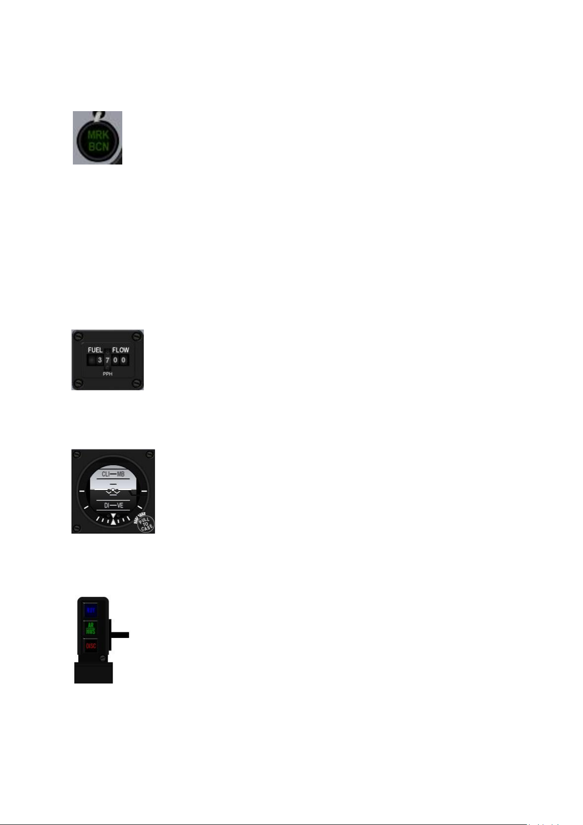
T.O. BMS1F-16CM-1 BMS 4.34 Change 2.00
BMS 4.34 Dash 1
© Red Dog 2012-2019 Page: 47
1.2.3.17 MARKER BEACON
The marker beacon is located to the right of the HSI above the FUEL QTY panel. Unlike
general aviation, where the markers are colour coded, in the F-16 it is only green but
blinks at a different frequency (with varying sound cues), according to the marker
overflown.
Marker beacons are short range transmitting devices placed alongside ILS approaches
and provide visual and audio cues when overflown. There are normally three markers: inner, outer and
middle markers along an ILS track. In BMS we only have outer (OM) and inner markers (IM)
implemented. They provide range information to the runway.
Outer markers are usually placed between 4 and 7 Nm (usually 6 Nm) from the runway threshold and
are at the point where the glideslope should be intercepted.
Inner markers are placed closer to the runway, usually 3500 feet and should be heard and seen in the
cockpit around 200ft above the ground, usually near the minima.
In BMS both markers light up the MRK BCN indicator making it flashes at different frequencies: (low
frequency for outer marker and higher frequency for inner marker). See the BMS-Comms-Nav-book in
your Docs folder for further information.
Please note: when the approach track is over water (e.g. Kunsan) the beacons are not installed.
1.2.3.18 FUEL FLOW indicator
Located above the RIGHT MFD this gauge displays the current fuel flow being
consumed by the engine (including in Afterburner) in pounds per hour (pph).
The gauge has a range from 0 to 80000 pph and is powered by the emergency
bus.
1.2.3.19 Backup ADI
The backup ADI is located above the RIGHT MFD and is the primary attitude
backup instrument.
It does not need power and will function even when the main ADI is flagged
OFF.
1.2.3.20 Right INDEXER
The RIGHT indexer features three coloured indicators arranged vertically.
The top one is blue and labelled RDY. It is relevant to the air-refuelling (AR) system
and comes on whenever the system is ready for air to air refuelling. In BMS this
indicator comes on as soon as the AR door is opened.
The centre indicator is green and labelled AR/NWS.
AR is only relevant when the aircraft is in the air and comes on whenever the boom is
inserted and has good contact with the AR receptacle on the back of the F-16.
NWS is relevant only when the aircraft is on the ground. It comes on when the Nose
Wheel Steering system is engaged, allowing the pilot to steer the aircraft using the rudder pedals to
control direction. It is recommended that nose wheel steering only be engaged below 70 knots on
landing and takeoff rolls and during taxiing.
The Bottom indicator is amber and labelled DISC. It is also relevant to the AR system and illuminates
when the pilot commands a disconnect from the boom.
Page 48

T.O. BMS1F-16CM-1 BMS 4.34 Change 2.00
BMS 4.34 Dash 1
© Red Dog 2012-2019 Page: 48
1.2.3.21 Right EYEBROW
On the edge of the right glareshield you will find a few more red warning
lights. All these lights are powered by the emergency bus.
• ENG FIRE / ENGINE - a split face indicator with two separate
illuminated cells. The top part (ENG FIRE) comes on whenever the
system detects a fire in the engine. The ENGINE warning light
illuminates when RPM and FTIT indicator signals indicate that an
engine over temperature or flameout has occurred. Illumination also
occurs for an engine alternator failure and may occur as a result of
an RPM or FTIT indicator failure. The warning light illuminates when the rpm decreases
below idle, or approximately 2 seconds after FTIT indication exceeds 1100°C. The warning
light goes off when the condition that turned it on is eliminated.
• HYD/OIL PRESS - serves as a monitor of engine oil pressure and hydraulic system pressure.
For engine oil pressure the warning light illuminates when oil pressure has been below
approximately 10 psi for 30 seconds (time delay minimizes warning light illuminating for false
warnings during manoeuvring).The light goes out when oil pressure exceeds approximately
20 psi. For hydraulic pressure, the warning light illuminates when either A or B system
pressure decreases below 1000 psi. The light goes out when both system A and B pressures
are above 1000 psi. During engine start the warning light usually goes off before reaching idle
rpm; however acceptable operation is indicated if the warning light goes off before exceeding
70 percent rpm and remains off when the throttle is retarded to idle.
• FLCS / DBU ON - The middle light is also a split face indicator and refers to the FLCS and
the Digital Backup (DBU) The FLCS warning light illuminates to indicate a dual malfunction in
the FLCC electronics, including the processors, power supplies, input commands or sensors,
AOA, or air data inputs. The FLCS warning light also illuminates if the LEFs are locked or
FLCS BIT fails. The FLCS warning light remains illuminated until FLCS reset action is
successful in clearing the failure. If an active warning fault exists and a subsequent warning
level malfunction occurs the FLCS warning light goes off momentarily to retrigger HUD
WARN and voice warning. The DBU ON light in BMS is eye candy only and comes on
whenever the DBU switch is activated on the FLCS panel.
• TO/LDG CONFIG - illuminates in flight whenever pressure altitude is less than 10000 feet,
airspeed is less than 190 knots, rate of descent is greater than 250 fpm and either of the
following conditions exists:
1. TEF's not full down.
2. NLG or either MLG not down and locked (accompanied by LG warning horn).
• CANOPY / OXY LOW - a split face indicator with the top part referring to the canopy and the
bottom one to oxygen.
The CANOPY light is lit up whenever the canopy is not locked in place.
The OXY LOW light comes on whenever the regulator pressure has dropped below 5 psi or
when the bit has detected a fault.
Page 49
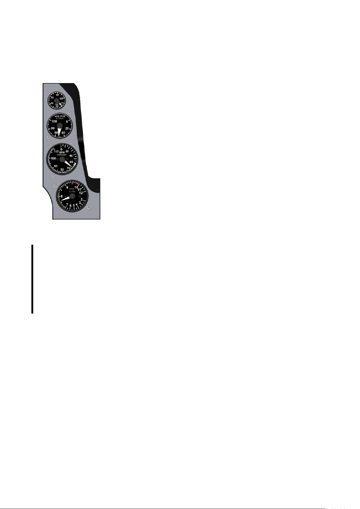
T.O. BMS1F-16CM-1 BMS 4.34 Change 2.00
BMS 4.34 Dash 1
© Red Dog 2012-2019 Page: 49
1.2.3.22 Right INSTRUMENT stack
The right instrument stack has 4 gauges all relevant to the engine. The top one
is the OIL pressure indicator, the second one is the NOZzle POSition indicator,
the third one is the RPM and the last one is the FTIT (Fan Turbine Inlet
Temperature).
Please note in BMS you can fly the block 50 F-16 with a GE 129 engine or a
block 52 model with a PW 229 engine. Other blocks with different engines can
be flown but are outside the scope of this manual.
• The OIL Pressure indicator displays engine oil pressure from 0 to 100
psi and is powered by emergency buses. There is a very small chance of an oil
pressure fault being triggered during engine start now in 4.34. If oil pressure
remains below 15 psi with the HYD/OIL warning light lit you will need to shut
down and restart the engine. Pay attention to this dial during ramp start.
• The NOZ POS indicator is a display of actual nozzle position ranging
from 0 % (closed) to 100 % (full open). The indicator is powered by emergency
buses.
• The RPM indicator has a pointer display expressed in percent rpm
from 0-110 % (on Ge129 engine) or 0-100 % (for PW229 engine). The indicator is powered by
the battery bus.
• The FTIT indicator displays the Fan Turbine Inlet Temperature in degrees Celsius.
The indicator has a range from 200°C to 1200°C in major increments of 100°C and is powered
by the battery bus.
This gauge also became much more important in 4.34 with the implementation of hot-start and
hung-start in both ground and air operations. You must now pay considerable attention to this
gauge during engine start to prevent engine damage in case of the FTIT going over the
temperature limit (800 °C for a ground start). See the Abnormal Procedures section for further
information.
Page 50
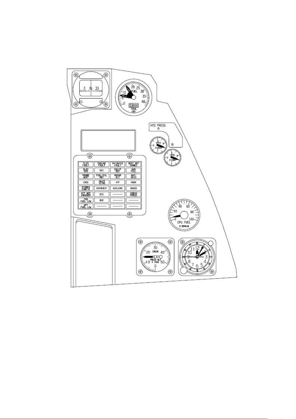
T.O. BMS1F-16CM-1 BMS 4.34 Change 2.00
BMS 4.34 Dash 1
© Red Dog 2012-2019 Page: 50
1.2.4. RIGHT AUXILIARY CONSOLE
Page 51
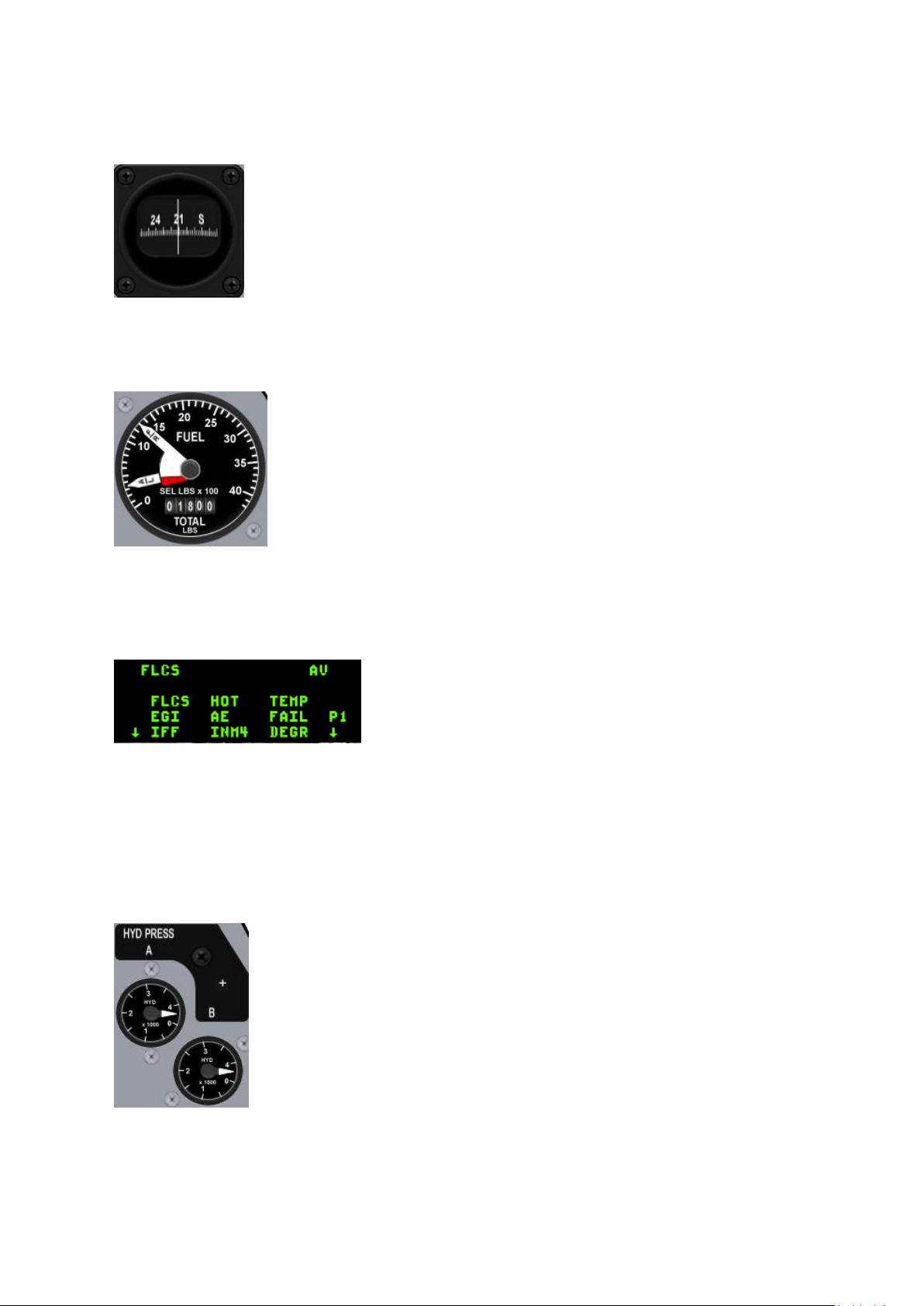
T.O. BMS1F-16CM-1 BMS 4.34 Change 2.00
BMS 4.34 Dash 1
© Red Dog 2012-2019 Page: 51
1.2.4.1 Compass
The magnetic compass is completely autonomous and doesn’t need any system
power to work. It is your ultimate backup navigation instrument. All four cardinal
directions are displayed as well as all 30° marks.
1.2.4.2 FUEL Quantity indicator
The FUEL QTY indicator gives your total fuel remaining on board (totalizer)
and its distribution in the internal forward/aft tanks or right/left tanks
(needles). Two needles labelled F/R & A/L display fuel quantity. The F/R
needle indicates the amount of fuel in the FRONT tank or RIGHT tank
depending on the position of the FUEL QTY SEL knob. The A/L needle
indicates the amount of fuel in the AFT tank or LEFT tank depending on the
position of the FUEL QTY SEL knob.
The A/L needle has a red centre portion that is visible only when a fuel
imbalance condition exists. For further information please refer to the Fuel
System chapter later in this manual.
1.2.4.3 Pilot Fault List Display
The Pilot Fault List Display (PFLD) is the same type of screen
as the DED and provides a list of faults detected in aircraft
systems mainly related to the FLCS, engine and avionics.
The display is blank until a fault is detected. The PFLD needs
UFC power to work.
The fault list is acknowledged page by page by the pilot via the F-ACK (fault acknowledge) button on
the left glareshield. The F-ACK button also provides fault recall on the PFLD. Unlike previous versions
of BMS pressing F-ACK when there is no active fault will not display NO FAULTS - ALL SYS OK on
the PFLD; the screen will remain blank, just like the real jet.
See chapter 3.4 PFL analysis for further information about the PFLD.
1.2.4.4 HYD PRESS system A & B gauges
The hydraulic system is a dual redundant system labelled A & B. You will find 2
hydraulic pressure gauges accordingly.
Normal operation pressure is around 3100 psi (needles at 12 o’clock on the
gauges).
Critical systems are served by both systems A and B and thus will fail only when
both hydraulic systems have run out of pressure. The EPU provides emergency
hydraulic pressure to system A only when required, but is limited in autonomy.
Refer to the EPU & Hydraulic chapter for further information.
Page 52
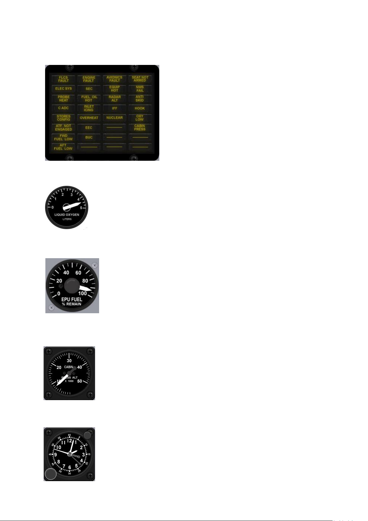
T.O. BMS1F-16CM-1 BMS 4.34 Change 2.00
BMS 4.34 Dash 1
© Red Dog 2012-2019 Page: 52
1.2.4.5 CAUTION light panel
The caution light panel features 26 amber caution lights.
Each of them will illuminate when a fault in the relevant
system is detected. For a full overview of each caution
light please refer to the Caution light analysis chapter.
One additional note: the ELEC SYS light can only be reset
with the ELEC CAUTION RESET button on the ELEC
panel (left console). The FLCS caution light is reset with
the FLCS reset switch.
1.2.4.6 LIQUID OXYGEN gauge
The liquid oxygen gauge points to the remaining oxygen in litres remaining in the
liquid oxygen tank.
Later versions of the F-16 do not have a liquid oxygen tank anymore and oxygen
relies on electrical power and engine bleed air to keep the supply going.
So this gauge may not be in your aircraft. When the oxygen is supplied by engine
bleed air the caution light OXY LOW is replaced by the OBOGS caution light.
1.2.4.7 EPU FUEL gauge
The EPU gauge indicates the quantity of EPU fuel (hydrazine) remaining.
Hydrazine is used if insufficient engine bleed air is available for running the
EPU. The gauge displays the percentage of EPU fuel remaining and depletes
fast when hydrazine is used. In normal operations you have an EPU operating
time of approximately 10 minutes. Use the following rule of thumb: 100 % = 10
minutes; 50% = 5 minutes. If the main and standby generators have failed the
EPU is out of fuel and the hydraulic system is depleted, so no flight controls
inputs are possible. Your only remaining option at this point is to eject.
1.2.4.8 CABIN PRESS ALT gauge
The cabin pressure gauge indicates cockpit pressure altitude from 0 to 50000
feet.
1.2.4.9 Clock
The clock, located on the right auxiliary console, is an 8 day, manually wound
clock with provisions for an elapsed time indication up to 60 minutes. In BMS it is
automatically set to mission time and does not take the day into account.
Page 53
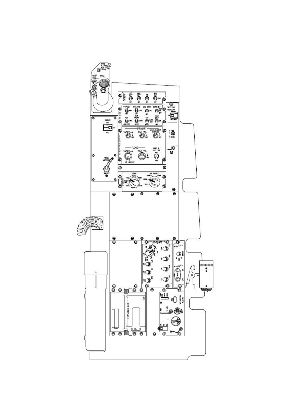
T.O. BMS1F-16CM-1 BMS 4.34 Change 2.00
BMS 4.34 Dash 1
© Red Dog 2012-2019 Page: 53
1.2.5. RIGHT CONSOLE
Page 54
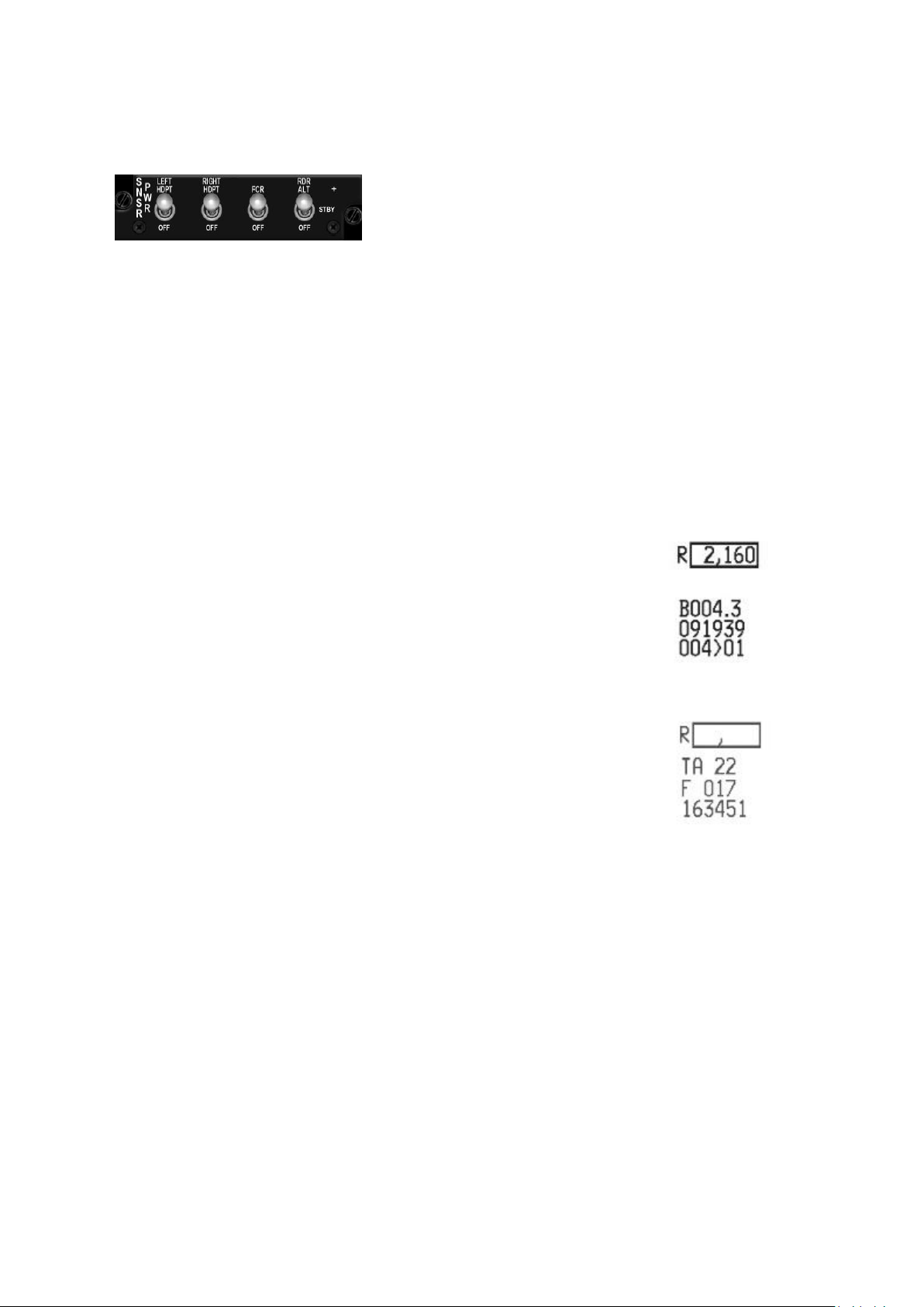
T.O. BMS1F-16CM-1 BMS 4.34 Change 2.00
BMS 4.34 Dash 1
© Red Dog 2012-2019 Page: 54
1.2.5.1 SNSR PWR Panel
The SENSOR panel features 4 toggle switches. The two left
most are power switches for the two chin intake pylons (LEFT
HDPT and RIGHT HDPT).
These pylons can carry pods (SNIPER, LANTIRN, HTS) and need power to function properly. With
the switches in OFF the pods get no power and will not work. Note also that some of these pods need
time after powering them up to be operational, so power up the pylons early enough in your flight.
The FCR switch is a two-state switch that powers up the Fire Control Radar (FCR). When powered up
the FCR enters a Power ON Built-In Test (PO BIT) mode, visible on the MFD. The BIT lasts about 3
minutes after which the radar is set to standby, unless previously set to a specific mode. The PO BIT
can't be interrupted in the middle of the test. The only way to 'truly' interrupt it is to turn the radar off.
Since the FCR is off at Ramp the FCR PO BIT has to be run completely when starting the jet from
cold for the FCR to function properly.
The PO (3 minute) BIT is performed whenever the radar power is switched to OFF for more than 4
seconds and then back on. A shorter Manual BIT lasting about 30 seconds can also be performed
through the MFD TEST page (OSB #19 FCR) or by switching the FCR switch to OFF for less than 4
seconds and then back on.
The RDR ALT switch is a three-position switch used to operate the radar
altimeter. With the switch in OFF the radar altimeter is inoperative. In STBY
the radar altimeter is placed in standby mode (used on the ground to avoid
frying your crew-chief). In RDR ALT the radar altimeter is fully operative.
RALT BIT is implemented and visible from the MFD TEST page (OSB 7).
When the radar altimeter is active the radar altitude can be read in the HUD in
the box preceded by the letter R.
Certain conditions must be met for the Radar altitude to be displayed. Those
conditions depend on altitude:
Low level the RALT will blank past 30° pitch and approximately 90° bank.
High altitude the RALT will blank above 10° pitch and approximately 75° bank.
Note the comma that remains displayed, even when the altitude is blanked.
BMS Key Callbacks for the Sensor panel:
SimLeftHptPower (toggle)
SimLeftHptOn
SimLeftHptOff
SimRightHptPower (toggle)
SimRightHptOn
SimRightHptOff
SimFCRPower (toggle)
SimFCROn
SimFCROff
SimRALTSTDBY
SimRALTON
SimRALTOFF
SimRALTUp
SimRALTDown
Page 55
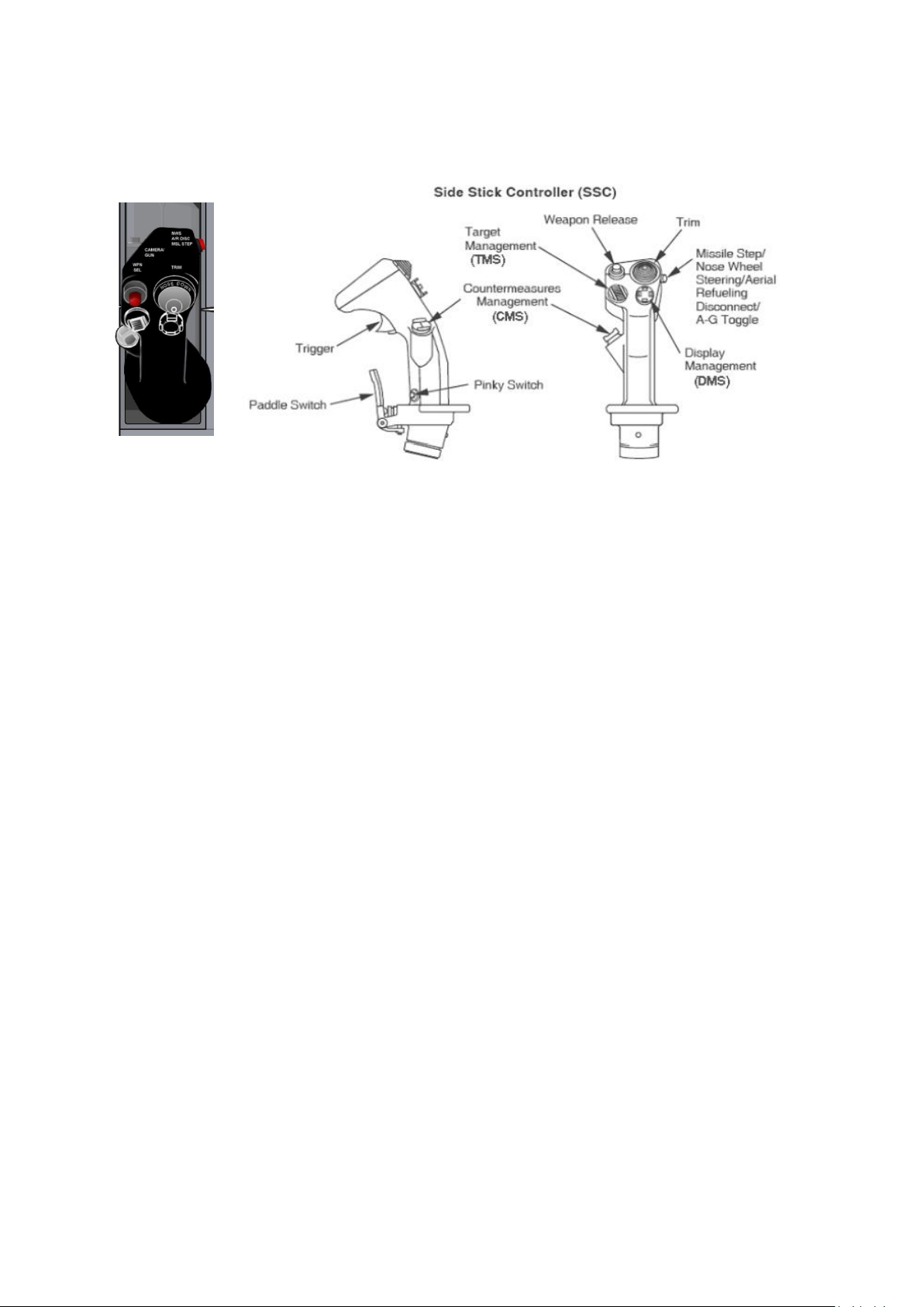
T.O. BMS1F-16CM-1 BMS 4.34 Change 2.00
BMS 4.34 Dash 1
© Red Dog 2012-2019 Page: 55
1.2.5.2 SIDESTICK CONTROLLER (SSC)
The stick in the real F-16 is a force sensing unit which contains transducers in both pitch and roll axes,
moves approximately 1/4 inch in both axes and is rotated slightly clockwise.
Refer to the diagrams on the two following pages for the function of each button.
BMS Key Callbacks for the Sidestick:
SimTMSUp
SimTMSDown
SimTMSLeft
SimTMSRight
SimDMSUp
SimDMSDown
SimDMSLeft
SimDMSRight
SimCMSLeft
SimCMSUp
SimCMSDown
SimCMSRight
SimPinkySwitch
SimHotasPinkyShift (DX callback)
SimAPOverride
SimTriggerFirstDetent
SimTriggerSecondDetent
SimMissileStep
SimPickle
AFAileronTrimLeft
AFAileronTrimRight
AFElevatorTrimUp
AFElevatorTrimDown
AFResetTrim
Page 56
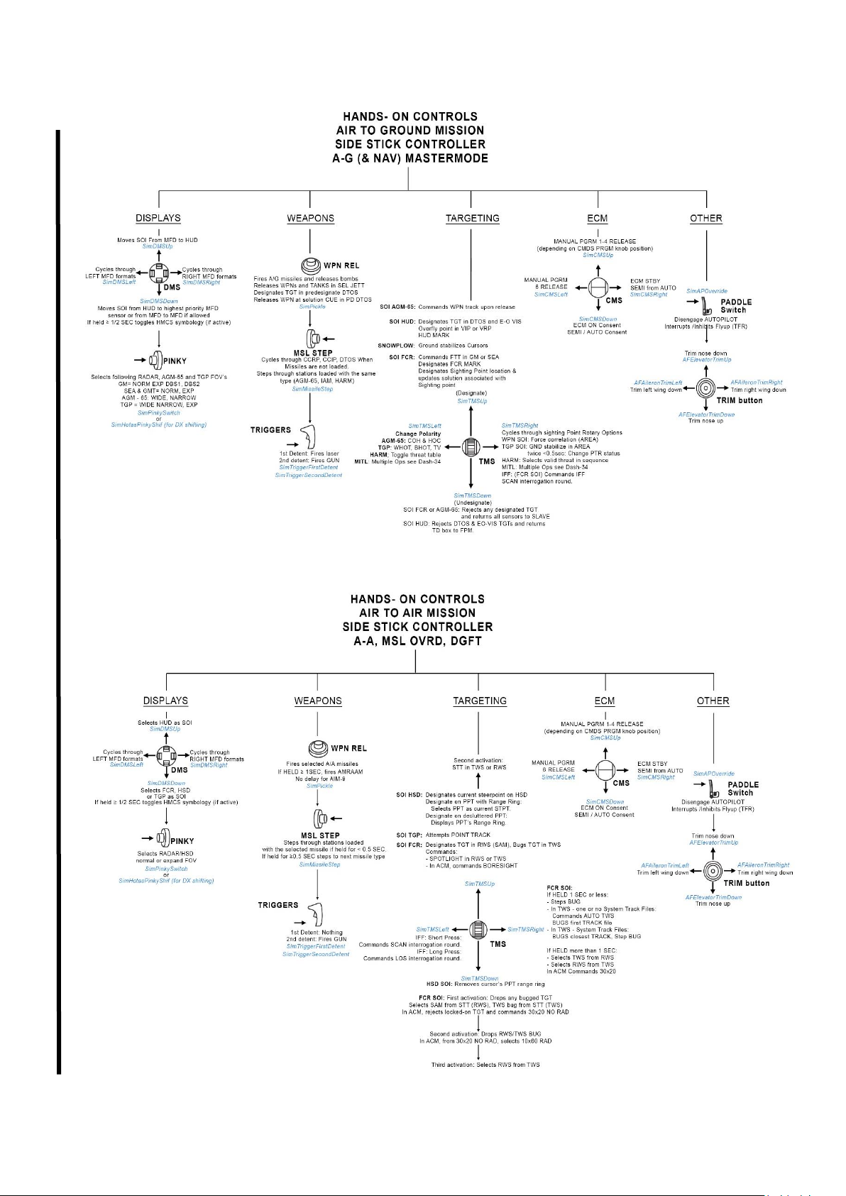
T.O. BMS1F-16CM-1 BMS 4.34 Change 2.00
BMS 4.34 Dash 1
© Red Dog 2012-2019 Page: 56
Page 57
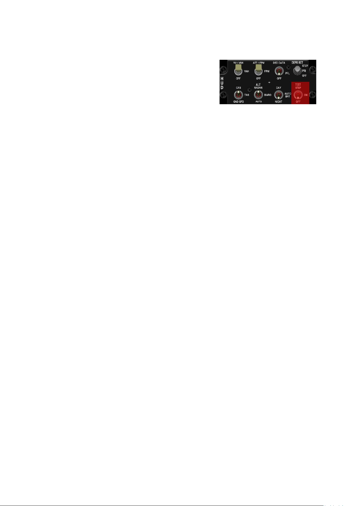
T.O. BMS1F-16CM-1 BMS 4.34 Change 2.00
BMS 4.34 Dash 1
© Red Dog 2012-2019 Page: 57
1.2.5.3 HUD panel
The HUD panel allows the pilot to customise the Head Up
Display. The panel is arranged in 2 rows of 4 toggle switches:
• The VV/VAH – VAH – OFF switch refers to the vertical
velocity scales found on the HUD.
In VV/VAH in addition to the vertical velocity scale there
is also a bank angle (15°/30°/45°/60°) indicator on the
FPM. In VAH there is a roll indicator below the heading tape (unless you have chosen to
display the DED or PFL in the HUD) with 10°/20°/30° and 45° cues. In OFF no scales or
bank/roll indication is displayed.
• The ATT/FPM – FPM – OFF switch refers to the pitch ladder and flight path markers (FPM).
In ATT/FPM, both the pitch ladder and flight path marker are displayed. In FPM only the flight
path marker is displayed. In OFF neither pitch ladder nor FPM is displayed.
• The DED DATA – PFL – OFF switch adds DED or PFL data to the bottom part of the HUD as
display repeaters.
When the switch is in DED DATA the DED is displayed in the HUD.
When the switch is centred on PFL the Pilot Fault List is displayed on the bottom of the HUD.
When the switch is set to OFF neither the DED nor the PFL is displayed on the HUD.
• The DEPR RET switch is a three-position switch labelled STBY, PRI and OFF. It is used for
standby bombing mode.
• The CAS –TAS – GND SPD switch controls display of the speed scale on the left of the HUD.
When CAS is selected the speed tape shows the Calibrated Airspeed. CAS is Indicated
airspeed (IAS) corrected for position & instrument error.
When TAS is selected the speed tape shows the True Airspeed. TAS is CAS corrected for
pressure altitude, so it is the airspeed in the air mass at this altitude.
When the switch is set to GND SPD, the HUD tape shows the speed over the ground.
Groundspeed is TAS corrected for winds.
In GND SPD a caret is also displayed on the heading tape. The caret means the system is
now in wind corrected ground track as opposed to showing heading as magnetic track.
Please note that whenever the landing gear is lowered the HUD airspeed automatically
reverts back to CAS, irrespective of the switch position.
• The ALT switch is a three-position switch labelled RADAR, BARO and AUTO and is relevant
to the altitude scale on the right of the HUD.
RADAR - the altitude tape indicates radar altitude.
BARO - the altitude tape indicates barometric altitude.
AUTO - the altitude tape indicates barometric altitude above 1500 feet and switches to radar
altitude below 1500feet.
More information can be found in the HUD chapter.
BMS Key Callbacks for the HUD panel:
SimHUDVelocityCAS
SimHUDVelocityTAS
SimHUDVelocityGND
SimHUDVelocity
SimHUDVelocityUp
SimHUDVelocityDown
SimHUDAltRadar
SimHUDAltBaro
SimHUDAltAuto
SimHUDRadar
SimHUDAltUp
SimHUDAltDown
SimHUDBrtDay
SimHUDBrtAuto
SimHUDBrtNight
Page 58
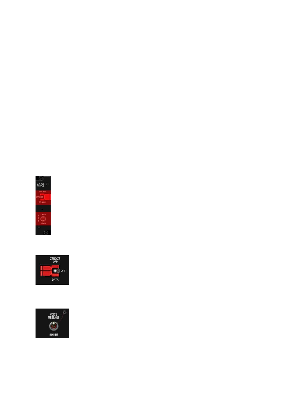
T.O. BMS1F-16CM-1 BMS 4.34 Change 2.00
BMS 4.34 Dash 1
© Red Dog 2012-2019 Page: 58
SimHUDBrightness
SimHUDBrightnessUp
SimHUDBrightnessDown
SimReticleSwitch
SimReticleSwitchUp
SimReticleSwitchDown
SimReticlePri
SimReticleStby
SimReticleOff
SimHUDFPM
SimPitchLadderOff
SimPitchLadderFPM
SimPitchLadderATTFPM
SimPitchLadderUp
SimPitchLadderDown
SimScalesVVVAH
SimScalesVAH
SimScalesOff
SimHUDScales
SimHUDScalesDown
SimHUDScalesUp
SimHUDDEDDED
SimHUDDEDPFL
SimHUDDEDOff
SimHUDDED
SimHUDDEDDown
SimHUDDEDUp
1.2.5.4 NUCLEAR panel
Currently not implemented.
1.2.5.5 ZEROIZE panel
Currently not implemented.
1.2.5.6 VMS panel
The Voice Messaging System (VMS) panel includes a single toggle switch. When
placed in the INHIBIT position VMS will be inhibited (Bitchin’ Betty remains silent).
When placed in the UP position VMS is operational.
BMS Key Callbacks for the VMS panel:
SimInhibitVMS
SimVMSOn
SimVMSOFF
Page 59
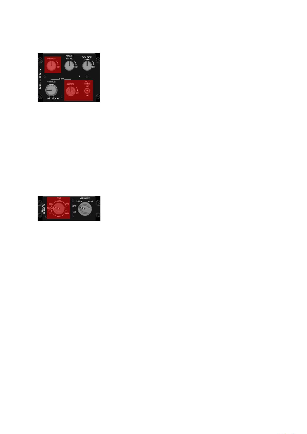
T.O. BMS1F-16CM-1 BMS 4.34 Change 2.00
BMS 4.34 Dash 1
© Red Dog 2012-2019 Page: 59
1.2.5.7 Internal LIGHTING panel
Internal lighting is not fully implemented in BMS.
Only 2 knobs are available to control cockpit lighting: the PRIMARY
INST PANEL for instrument backlighting and the FLOOD CONSOLES
knob for cockpit flood lights.
The third knob implemented controls DED brightness.
Each knob has three-position: OFF, DIM, BRIGHT, which cannot be
assigned to an analogue value.
BMS Key Callbacks for the INT LIGHT panel:
SimInteriorLight
SimInteriorLightCW
SimInteriorLightCCW
SimInstrumentLight
SimInstrumentLightCW
SimInstrumentLightCCW
SimSpotLight
SimDedBrightness
SimDedBrightnessCW
SimDedBrightnessCCW
1.2.5.8 AIR COND panel
The AIR COND panel is made of two large knobs. The first one for
TEMP is not implemented, but the second labelled AIR SOURCE is.
OFF - the engine bleed air valves close. All air conditioning, cooling and
pressurizing functions shut off, meaning no cockpit pressurisation,
system cooling or external fuel tank pressurisation (preventing fuel
transfer from external tanks).
NORM - the air conditioning system sets for automatic temperature and pressure regulation. Cockpit
and fuel tanks are pressurized and avionics are cooled.
DUMP - cabin pressurisation is terminated and the cockpit is vented to outside air pressure. This
means cockpit pressure altitude will increase above 8000 feet MSL. The CABIN PRESS caution light
will illuminate if cockpit pressure altitude exceeds 27000 feet. All other ECS functions such as
external fuel tank pressurisation are unaffected.
RAM - engine bleed air valves close. Cabin pressurization is terminated and the cabin is vented to
outside air pressure as above. RAM air valves are opened to ventilate the cockpit and avionics. All
other ECS functions such as external fuel tank pressurisation & cooling are disabled.
BMS Key Callbacks for the AIRCOND panel:
SimIncAirSource
SimDecAirSource
SimAirSourceOff
SimAirSourceNorm
SimAirSourceDump
SimAirSourceRam
Page 60
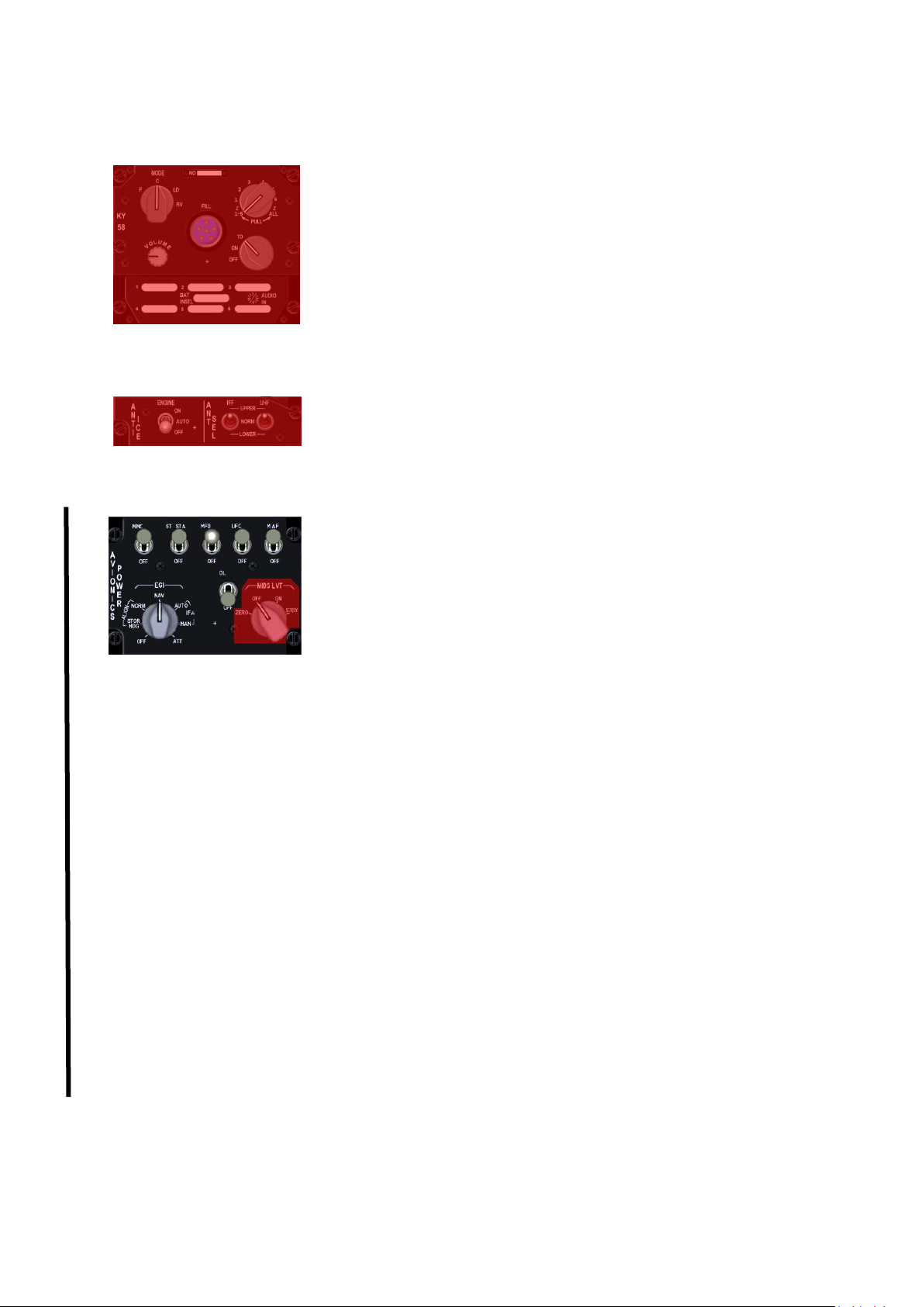
T.O. BMS1F-16CM-1 BMS 4.34 Change 2.00
BMS 4.34 Dash 1
© Red Dog 2012-2019 Page: 60
1.2.5.9 KY 58 panel
Currently not implemented.
1.2.5.10 ANTI ICE panel
Currently not implemented.
1.2.5.11 AVIONICS POWER panel
As the name implies, the AVIONICS POWER panel is used to power up
avionic systems. It is made of 6 locking toggle switches and two knobs.
MMC - enables power to the Modular Mission Computer (old FCC).
ST STA - enables power to the Store Stations (old SMS).
MFD - enables power to the Multi-Function Displays.
UFC - enables power for the Up Front Controls.
MAP – is not wired, has no function but can be moved.
DL - enables power to the data link receiver.
The INS has been replaced by EGI (Embedded GPS/INS) in our block 50/52. That explains the
deletion of the GPS switch on the old Avionic panel. The following positions are implemented in BMS:
OFF, ALIGN NORM, NAV, IN-FLT ALIGN. The position ALIGN STOR HDG and ATT are not
implemented.
OFF positions terminates all INS functions.
Place the knob to ALIGN NORM to start a normal alignment. The EGI is usable after 90 seconds
when it has heading information. At that point the AUX yellow flag on the ADI disappears and a
steady RDY is displayed in the HUD and DED. Those are your visual cues for performing a short
ramp procedure. Full alignment takes approximately 4 minutes rather than the old 8 minutes with the
INS. At that point RDY flashes in the HUD and on the DED to indicate full alignment.
Once the EGI is ready, switch the EGI knob to NAV to allow the EGI system to provide navigation
information to the navigation system. Please note: navigation cues will only be displayed when the
EGI knob is set to NAV. During normal alignment the navigation cues are not displayed (flight plan on
HSD etc).
In case of EGI failure or problem an IN FLIGHT alignment can be performed. The EGI is then
realigned according to GPS data provided by the GPS system. During in-flight alignment straight,
level and un-accelerated attitude should be maintained until the EGI reports a state at or above 8.1.
Normally the magnetic heading should be entered manually in the DED, but that is not required in
current BMS code
The MIDS LVT knob is not implemented. It is a digital TACAN system. The knob is supposed to turn
the TACAN transmitter/receiver ON and OFF. IN BMS, TACAN is always ON
Page 61
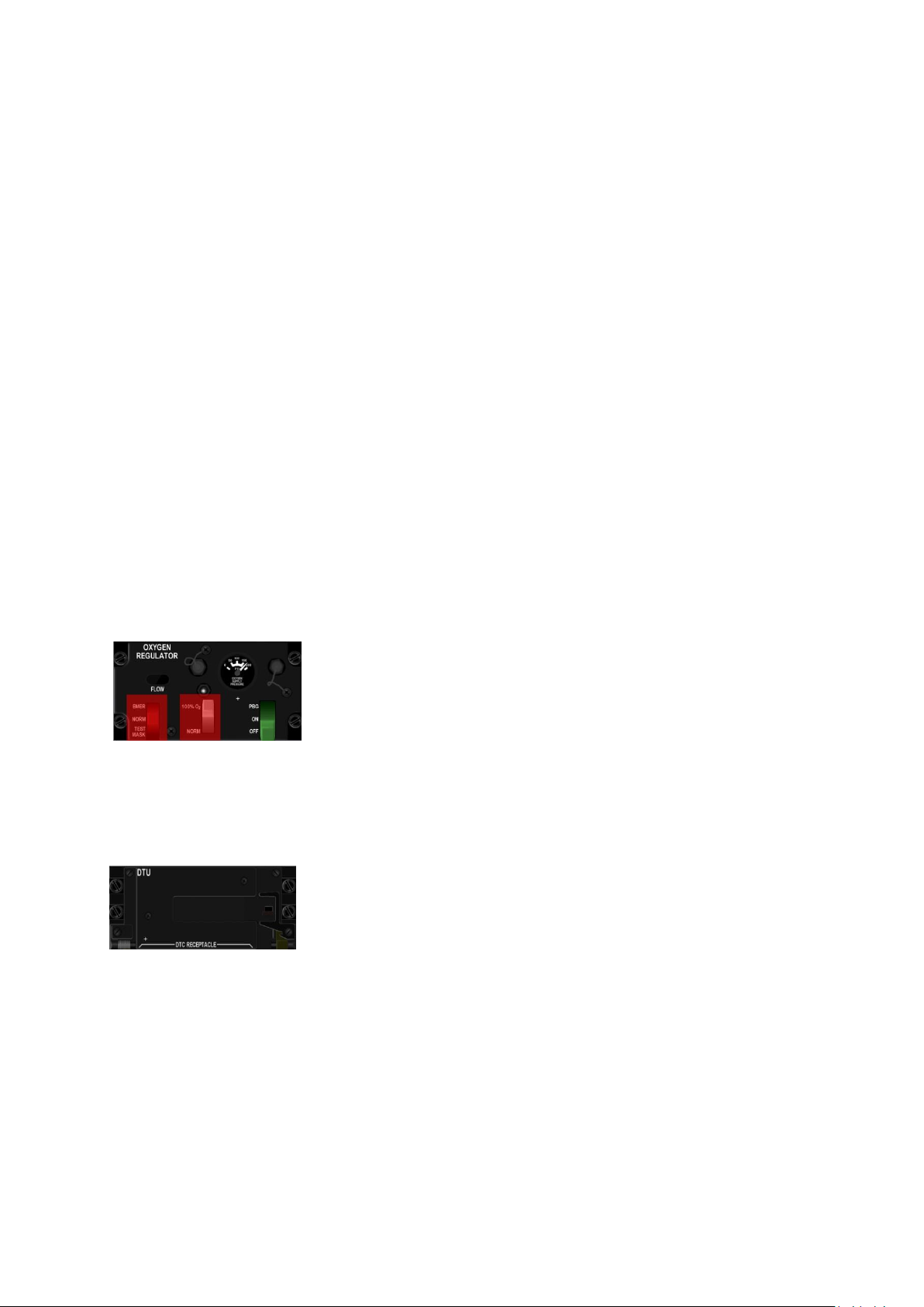
T.O. BMS1F-16CM-1 BMS 4.34 Change 2.00
BMS 4.34 Dash 1
© Red Dog 2012-2019 Page: 61
BMS Key Callbacks for the AV Power panel:
SimINSInc
SimINSDec
SimINSOff
SimINSNorm
SimINSNav
SimINSInFlt
SimSMSPower
SimSMSOn
SimSMSOff
SimFCCPower
SimFCCOn
SimFCCOff
SimMFDPower
SimMFDOn
SimMFDOff
SimUFCPower
SimUFCOn
SimUFCOff
SimGPSPower
SimGPSOn
SimGPSOff
SimDLPower
SimDLOn
SimDLOff
SimMAPPower
SimMAPOn
SimMAPOff
1.2.5.12 OXYGEN REGULATOR panel
The Oxygen panel is not implemented in BMS but the green lever can
be used to toggle on or off the sounds of the pilot breathing through the
oxygen mask.
BMS Key Callbacks for the Oxygen panel:
SimOxySupplyToggle
SimOxySupplyOn
SimOxySupplyOff
1.2.5.13 DTU panel
Currently not implemented.
Page 62
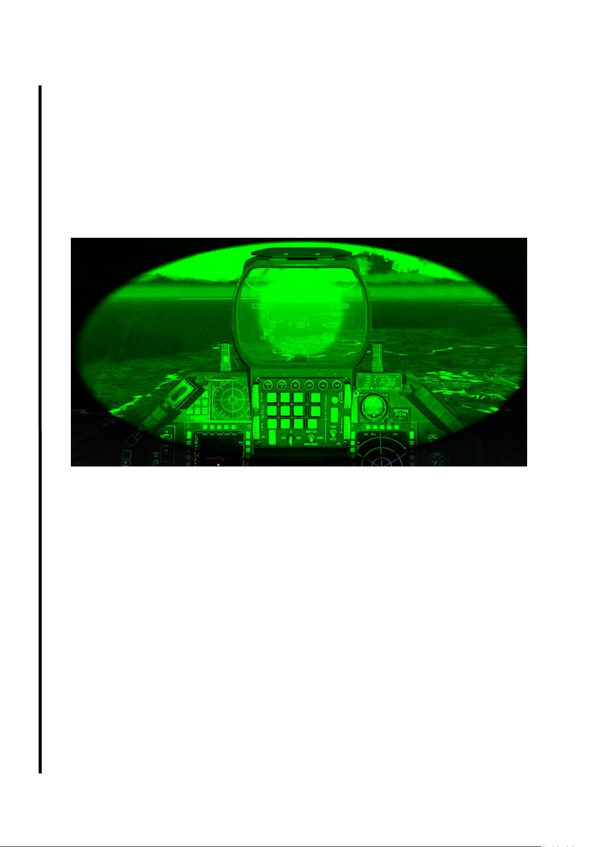
T.O. BMS1F-16CM-1 BMS 4.34 Change 2.00
BMS 4.34 Dash 1
© Red Dog 2012-2019 Page: 62
1.2.6. MISCELLANEOUS
There are a few controls that are accessible to the pilot but not from cockpit controls. We will cover
them in this small section.
1.2.6.1 NVG
Night vision googles are normally powered from the helmet, hence there is no cockpit control (thus no
mouse hotspot) for them. You will have to activate them with the relevant callback associated to a
keystroke (“n” by default). it’s a toggle so it can be easily activated or deactivated.
NVGs in BMS are restricting the pilot field of view and try to simulate tunnel vision.
The resolution of your main screen might impact the NVG as the DDS masks by default is made for
1920x1080 resolution. If you use other screen resolution, it is best to adapt the NVG mask DDS for a
matching resolution, or use one of the NVGs mask made by the community.
BMS Key Callbacks for NVG:
SimNVGModeOn
SimNVGModeOff
Page 63
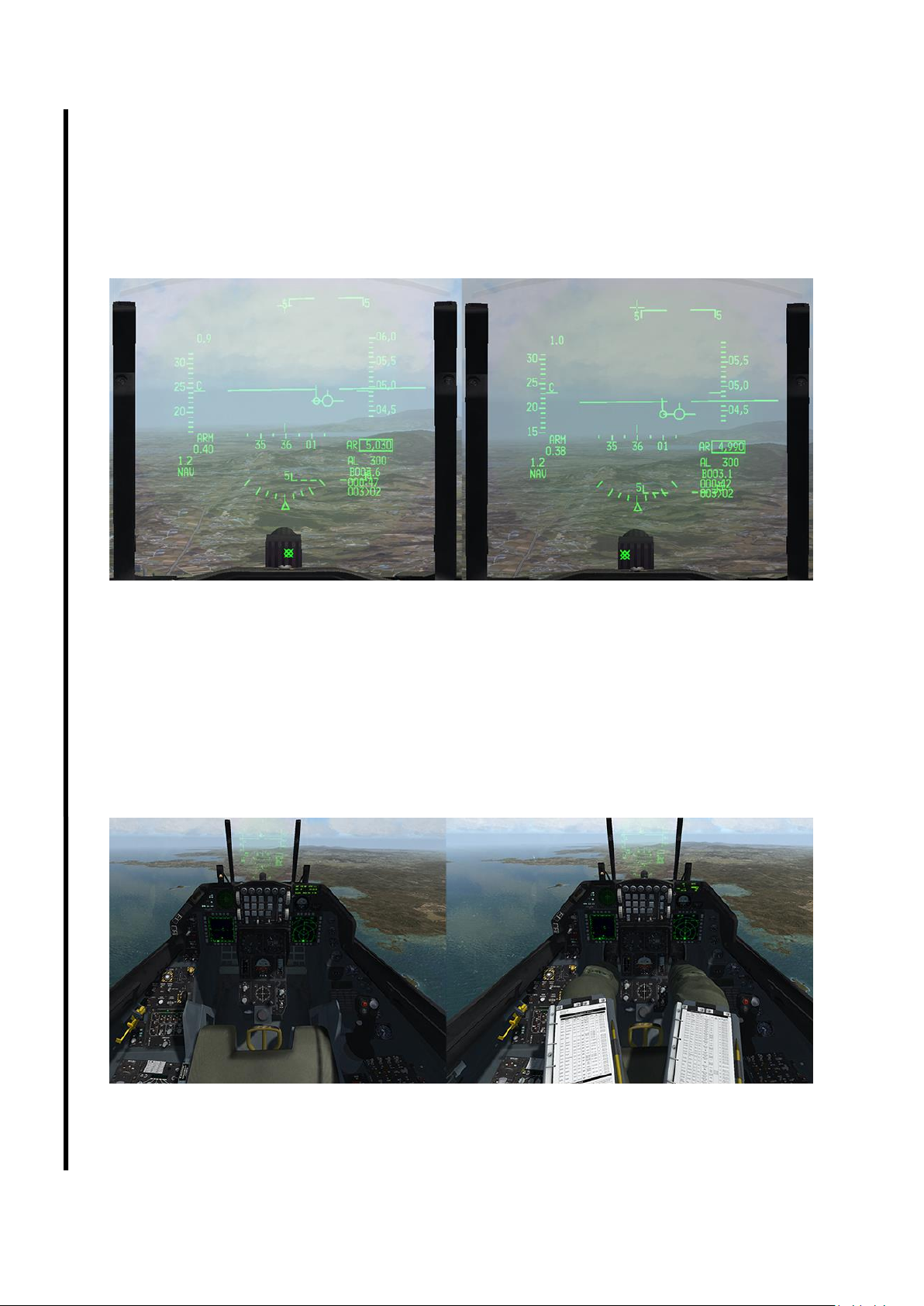
T.O. BMS1F-16CM-1 BMS 4.34 Change 2.00
BMS 4.34 Dash 1
© Red Dog 2012-2019 Page: 63
1.2.6.2 HELMET VISOR
For a long time the lack of contrast of the HUD against the clear blue sky created readability issues for
many of us. BMS 4.34 introduced a visor mask that increases the contrast by lowering the brightness
of the sky. Exactly like a pilot lowering his flying helmet dark visor in front of his eyes.
Just like the NVG it is a toggle and there is no hotspot in the cockpit for this as it is initiated on the
helmet itself. You will therefore have to use the relevant new callback associated to a keystroke
(default ALT v), which can be mapped to a spare HOTAS button to allow convenient access in flight.
BMS Key Callbacks for Visor:
SimVisorToggle
1.2.6.3 PILOT MODEL
Before 4.34 the F-16 cockpit was empty. Harpoon’s popular pilot model has been added by default
into the cockpit with two kneeboards where relevant dynamic flight information can be displayed.
These DDS files can be manually edited or created very easily with Weapon Delivery Planner. This
pilot model can block some panel views, so can be deactivated either through UI options (SETUP >
GRAPHICS) or in 3D with a keystroke associated with a callback (default ALT c then p).
BMS Key Callbacks for Pilot model:
SimPilotToggle
Page 64
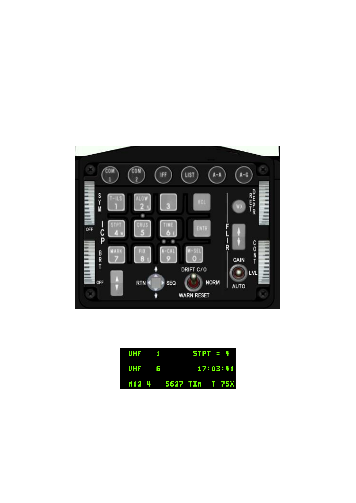
T.O. BMS1F-16CM-1 BMS 4.34 Change 2.00
BMS 4.34 Dash 1
© Red Dog 2012-2019 Page: 64
1.3 UP FRONT CONTROLS
The UFC is made up of a display called the Data Entry Display (DED) and a keyboard known as the
Integrated Control Panel (ICP).
Both work together to provide the pilot with an easy way to interface with the avionics system of the
aircraft. Every press on an ICP button opens a page or changes information on the DED. The DED
needs UFC power to work. Please note it will not turn on immediately at UFC power up (during ramp
start) but requires a few seconds for the display to come online.
Fig1: The ICP
Fig 2: The DED
Page 65
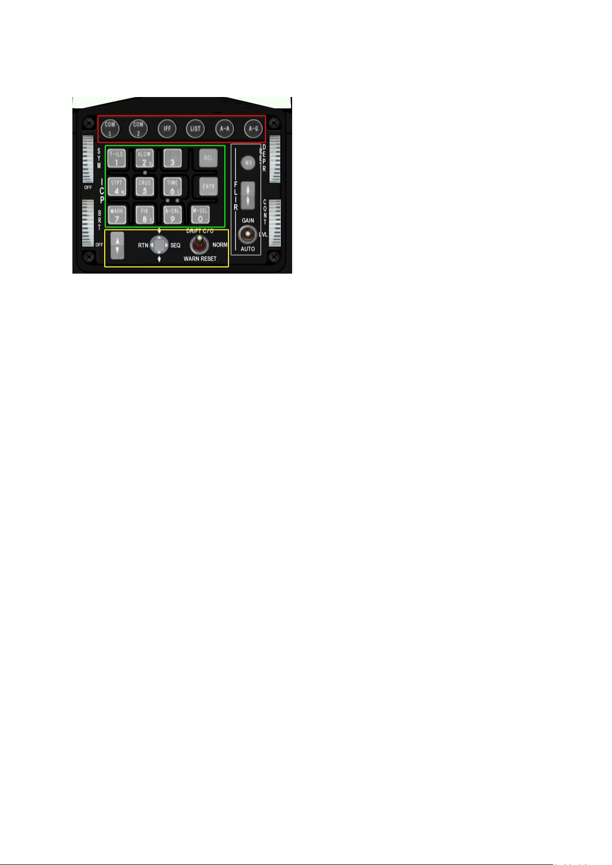
T.O. BMS1F-16CM-1 BMS 4.34 Change 2.00
BMS 4.34 Dash 1
© Red Dog 2012-2019 Page: 65
The ICP is arranged into 5 different areas:
The top row with round pushbuttons (red), the entry
pad with square pushbuttons (green) the FLIR zone
(grey), the bottom part (yellow) with switches and
the 4 outboard wheels.
More importantly, we can classify the ICP buttons in
other more relevant categories:
• Master Modes
• Override Modes
• Priority buttons.
The F-16 avionics system has the following components controlled from the ICP:
7 Master Modes
1. Air to Air (A-A ICP button)
2. Air to Ground (A-G ICP button)
3. NAV (when none of the A-A or A-G modes are engaged)
4. DGFT - Dogfight (toggle switch on the throttle)
5. MRM/SRM – Missile Override (toggle switch on the throttle)
6. S-J Selective Jettison (SMS page on MFD)
7. E-J Emergency Jettison (while the E-J button is depressed)
Master Mode buttons automatically configures the system for specific actions. They can change MFD
pages, DED pages and HUD pages all at once.
5 Override Modes
1. COM1 (ICP button)
2. COM2 (ICP button)
3. IFF (ICP button)
4. LIST (ICP button)
5. F-ACK (left glareshield pushbutton)
Override modes provide direct access to the functions of the corresponding button. You can revert
back to the initial page by pressing the override mode button again.
In addition to the 5 override modes there is a special override mode that returns the UFC to CNI
(Communication, Navigation & Identification) page on the DED. That mode is accessed by moving the
DCS (Data Command Switch) to the left (RTN position).
8 Priority/secondary buttons:
These are the ICP square buttons labelled T-ILS, A-LOW, STPT, CRUS, TIME, MARK, FIX and ACAL. The two last are not implemented in BMS.
These buttons have a dual function; they are used to input numerical data into the UFC/DED or to
enter UFC/DED subpages according to the labelling listed above.
Numerical values can be entered in the scratchpad. The scratchpad is the area between two asterisks
displayed in the DED. Anytime you see the scratchpad active the numerical value of the ICP button
from 0 to 9 will be used when you press these buttons. Note that the numerical zero is entered using
the M-SEL 0 button, this button has no secondary page call up function.
Page 66
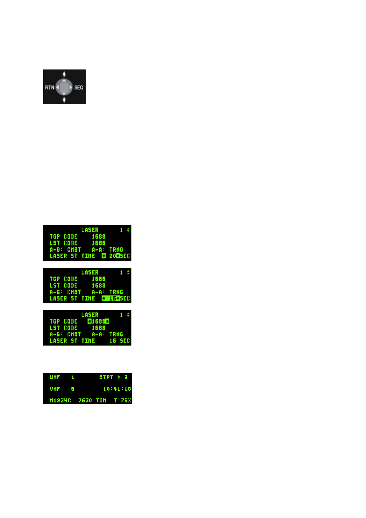
T.O. BMS1F-16CM-1 BMS 4.34 Change 2.00
BMS 4.34 Dash 1
© Red Dog 2012-2019 Page: 66
1.3.1. Data Command Switch (DCS) & scratchpad
The DCS is a four way momentary switch situated on the bottom row of the ICP, next
to the DRIFT C/O – WARN RESET switch.
The LEFT position is labelled RTN and allows exit from the current DED page or
return to the CNI DED page.
The top position is labelled with an up arrow and cycles the DED cursors to editable
functions (scratchpad) moving upward.
The bottom position is labelled with a down arrow and cycles the DED cursor to editable functions
downward.
The right position is labelled SEQ and is used to enter extra subpages or options of the current priority
function.
1.3.2. ENTR and RCL button
Those two buttons have no priority functions and only serve to confirm or cancel the entered data.
After entering data in the scratchpad the ENTR button must be depressed to submit the changed data.
The system checks if the data is valid and if it is enters it, then moves on to the next editable area. If
the data is invalid the inputted data will flash and the pilot will have to correct any errors.
The RCL (Recall) will clear the last data entry. If pushed twice in succession the entire scratchpad will
be cleared.
1.3.3. DED scratchpad
The scratchpad is an editable area receiving alphanumeric values
from the ICP keys. The scratchpad area is displayed in the DED
between two asterisks.
The scratchpad area on the left picture is around the Laser Start
Time, which is initially set to 20 seconds before weapon impact.
Any press on the ICP buttons will change the numerical value. For
instance, if we press 1 then 6 the laser time will change to 16
seconds when the ENTR key is pressed and the scratchpad is
moved automatically to the next area (if the data is valid) or
manually by moving the DCS switch up or down.
To return to the default DED (CNI) page, move the DCS to the RTN
(left) position.
Anytime the scratchpad is not active a press of a priority button will
enter the relevant subpage.
Each of them is covered later in this section.
1.3.4. CNI page
The Communication, Navigation and Identification DED page (CNI)
is the default page for the DED.
It displays information about the current radio settings for both
COM1 & COM2 radios, the active steerpoint, current time, IFF mode
& codes and active TACAN or DME when A/A TACAN is active.
The CNI page is only accessible when the CNI switch on the AUX COMMS panel is set to UFC. When
placed in BACKUP the UFC is inoperative and all backup systems are active and controlled from the
side consoles.
Note the up and down arrow on the steerpoint on the CNI page. This shows that the current steerpoint
can be incremented or decremented with the PREV/NEXT button of the ICP (the rocker switch located
left of the DCS) without leaving the CNI page. As with the scratchpad, the arrows can be cycled
through the fields that can be edited by moving the DCS up and down.
Page 67
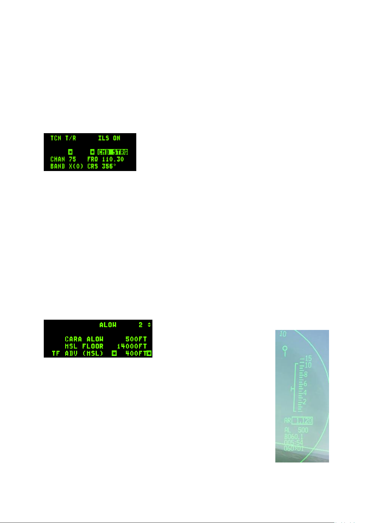
T.O. BMS1F-16CM-1 BMS 4.34 Change 2.00
BMS 4.34 Dash 1
© Red Dog 2012-2019 Page: 67
Moving the DCS right to SEQ in the CNI page will display the current wind speed and direction on the
DED but valid data is only available once sufficient airflow is feeding data to the probes. There is no
wind indication on the ground in BMS as in the real aircraft, so ask the ATC for a wind check or get the
ATIS.
The system time is displayed and if a hack time is activated, the hack clock will be displayed below the
system time. (see TIME subpage).
1.3.5. T-ILS page (1)
This page refers to the TACAN and ILS settings. You can access it through the T-ILS ICP button.
The first line of the DED gives the TCN and ILS status (ILS is turned on/off with the ILS knob on the
AUDIO2 panel).
The scratchpad is on the left between the two asterisks and that is
where the TACAN & ILS frequencies are entered. The system is
able to differentiate a valid TACAN channel (0-126) from a valid
ILS freq (VHF 4 or 5 digits). The next line gives the current and
active TACAN and ILS frequencies respectively and the last line
displays the TACAN band (X or Y) and the CRS set for the ILS approach.
To enter a new TACAN channel or an ILS frequency simply input the relevant numbers within the
asterisks and hit ENTR.
To change the TACAN band: input 0 (zero) in the scratchpad and press ENTR. That toggles from X to
Y to X and so on.
To change the TACAN from T/R (ground domain) to A/A TR (air domain) use the DCS SEQ button.
ILS CMD STRG can be inhibited or activated by placing the scratchpad over it and mode selecting it
with the M-SEL 0 ICP pushbutton. The CMD STRG line in the DED is highlighted when command
steering is active.
To change the ILS course place the scratchpad on the CRS field using DCS up/down and enter the
correct runway heading for the active ILS. Press ENTR to input the data into the system.
1.3.6. A-LOW page (2)
The Altitude-LOW page lets the pilot set different values for the altitude advisory system.
It is made up of three lines but before we get to that, please note the top right number with the arrows
on the right. This is the active steerpoint; the arrows mean that the active steerpoint can be changed
with the PREV/NEXT buttons of the ICP without leaving the
A-LOW page.
Move the scratchpad up and down with
DCS up and down to select a field to
edit.
CARA ALOW is the altitude in feet where you want an advisory altitude warning.
It is mainly used for low altitude flying. The inputted value is repeated in the HUD
next to the AL notation and flashes when the actual altitude goes below that
CARA ALOW. If the gear is up VMS will also produce an aural ALTITUDE call.
A caret is placed at the ALOW height on the AUTO altitude HUD scale.
The CARA ALOW function will work only if the radar altimeter is operating.
MSL FLOOR is your Minimum Safe Level floor. It is DTC loadable and one typical
approach is to set this to 14000 feet to correspond with the transition altitude in
Korea. That ensures that when descending below 14000 VMS calls ALTITUDE,
reminding the pilot to switch to local QNH for the altimeter calibration setup.
TFR ADV is an advisory altitude below which the red CHECK ATTITUDE box will
flash. It’s usually set at MSA (Minimum Safe Altitude). See the TFR MFD page for
further information, or the TFR chapter in the TO BMS1-F16CM-34-1-1 manual.
Page 68
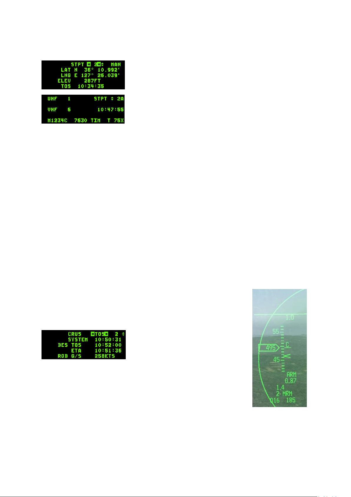
T.O. BMS1F-16CM-1 BMS 4.34 Change 2.00
BMS 4.34 Dash 1
© Red Dog 2012-2019 Page: 68
1.3.7. STPT page (4)
The Steerpoint page gives the pilot information about the INS
steerpoint.
The first line allows the pilots to toggle the active steerpoint with the
NEXT/PREV ICP buttons (notice the up & down arrows) and the
MAN or AUTO steerpoint function, which can be toggled with DCS
SEQ. MAN means that the new steerpoint has to be manually
selected. AUTO will increment to the next steerpoint automatically
when the INS detects the proximity of the current waypoint. In AUTO
mode an “A” symbol is displayed on the CNI page next to the
steerpoint, as seen in the screenshot on the left.
The second line is the LATITUDE of the currently selected steerpoint. Placing the scratchpad there will
let the pilot enter the latitude for this particular navigation point. The latitude must start by inputting
NORTH by pressing ICP #2 key (notice the small N on that key) then the relevant numbers can be
input. The scratchpad will not respond until the cardinal key is pressed.
The third line is the LONGITUDE of the selected steerpoint. It can also be changed by placing the
scratchpad accordingly and entering new coordinates. The longitude must start by inputting EAST by
pressing ICP #6 key (notice the small E on that key) then the relevant numbers can be input. The
scratchpad will not respond until the cardinal key is pressed.
The fourth line is the elevation of the steerpoint (the altitude at which you are supposed to overfly the
steerpoint according to your INS flight plan). This is different from the real jet that has the ground spot
height for steerpoint in this field (it is quite relevant to TGP mechanisation and finding the target).
The fifth line is the TOS (Time Over Steerpoint) which gives you the local time the steerpoint will be
reached, if you are following the route of flight as planned.
1.3.8. CRUS page (5)
The Cruise page provides access to 4 submodes: TOS, RNG, HOME and EDR and gives relevant
information for navigation, time and fuel while cruising.
Each submode must be mode selected to become active and supply accurate information and cues.
Remember mode-selecting is done with the M-SEL 0 button and when active highlights the area.
The submodes of the CRUS page are accessed sequentially with DCS SEQ or
by pressing any secondary ICP button.
When first entering the CRUS page it defaults to the first subpage: TOS (Time
Over Steerpoint).
When TOS is mode selected a caret is
displayed on the HUD speed tape. To
ensure that you reach the steerpoint on time
for TOS match your airspeed with the caret.
The ETA (Estimated Time of Arrival) to the
steerpoint is also displayed in the HUD.
When TOS is not mode selected (it no longer is by default since 4.33 just like
in the real jet) no caret is active on the HUD speed tape and ETE (Estimated
Time Enroute) is displayed in the HUD.
You can change your TOS and assign a new one by simply inputting a new
value in the scratchpad when the asterisks are around the DES TOS.
Further information on the TOS page includes the current system time, ETA at steerpoint and required
ground speed to get there at the indicated DES TOS.
Page 69
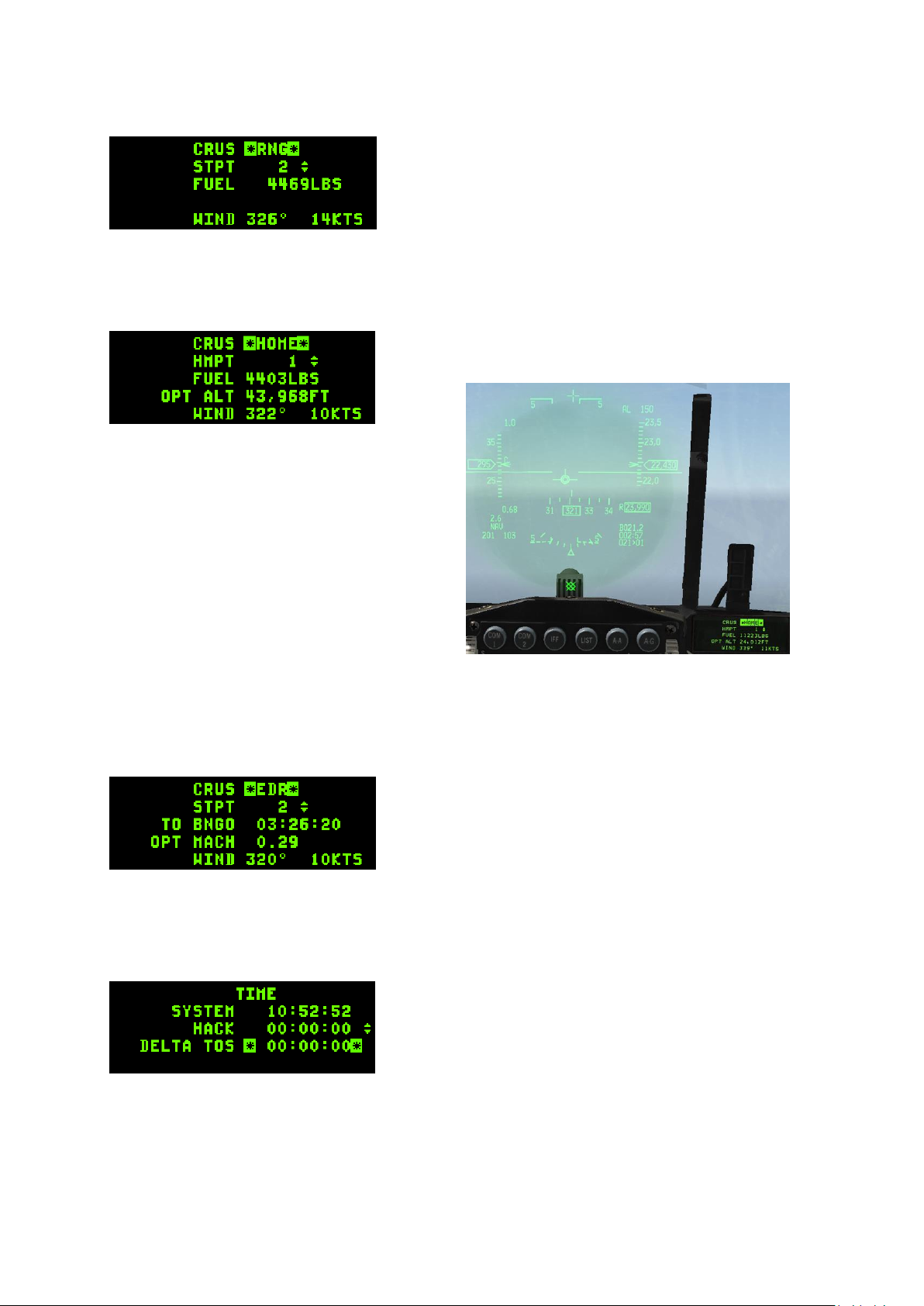
T.O. BMS1F-16CM-1 BMS 4.34 Change 2.00
BMS 4.34 Dash 1
© Red Dog 2012-2019 Page: 69
The next Submode is RNG for Range.
When RNG is mode selected a caret is displayed on the HUD
speed tape to pinpoint the best conserve fuel speed at this
altitude. Optimum speed for fuel conservation changes with
altitude.
When RNG is not mode selected there is no caret displayed
on the HUD speed tape. Please note on the picture RNG
mode is NOT mode selected. Only the active steerpoint can be toggled on this subpage. Additional
information given on this page shows fuel remaining when reaching the active steerpoint, wind
direction and speed.
A further press of DCS SEQ brings up the HOME subpage.
When HOME is mode selected 2 carets are displayed in the
HUD on the speed tape and on the altitude tape. Following
these 2 carets will establish the best profile to reach Home
Plate (or
any
steerpoint designated as HMPT).
The procedure to fly this profile is to select full
military power, reach the speed caret first then
pitch to reach the altitude mark while maintaining
the speed on the caret. Altitude may vary
according to fuel burned. Please note, optimal
altitude is given in radar altitude on the DED, but
may be different on your HUD scale depending
on the altimeter setting. Check the picture on the
right, both carets are followed and the optimum
altitude in the DED matches the HUD radar
altimeter. If you follow both carets you will reach
the home point at the selected optimum altitude.
The altitude caret will disappear once you can start your descent.
Further information displayed on this page indicates home point (can be changed to any INS
steerpoint (e.g. alternate)), onboard fuel quantity remaining when reaching active steerpoint, optimum
altitude for the HOME profile, wind direction and speed.
The last subpage of the CRUS page is the Endurance mode (EDR)
When EDR mode is mode selected a speed caret is placed
on the HUD tape to give a reference speed for best
endurance at this altitude. This is very useful for holding
patterns or maximum endurance cruise for instance. Further
information given is time to bingo, optimum Mach number and
wind direction and speed.
It is important to realise that when toggling from one submode to another you must always mode
select the new mode. If you don’t do so the caret may be relevant to the previous CRUS submode. So
to avoid any confusion make sure you always mode select the submode!
1.3.9. TIME page (6)
The TIME page allows the pilot to set a HACK timer and a
DELTA TOS for ROLEX calls. The first line gives the current
system time. The second line is the hack timer. As the arrows
indicate, pressing the ICP NEXT rocker button will
start/freeze/resume the timer and ICP PREVIOUS rocker
button will reset the hack timer to zero.
When the HACK timer is running it is also visible on the CNI page. ROLEX calls are initiated when
TOS for all steerpoints need to be adjusted. This is done through the TIME page by changing the
DELTA TOS. Place the scratchpad on the DELTA TOS line and input the ROLEX value. If a minus is
required start your input with the 0 (zero) ICP key for the minus sign.
For instance: “Mamba flight Rolex +2” => TIME, DCS down to DELTA TOS: 2, 0, 0, ENTR
Another example: “Mamba flight Rolex -3” => TIME, DCS down to DELTA TOS: 0, 3, 0, 0, ENTR
Page 70
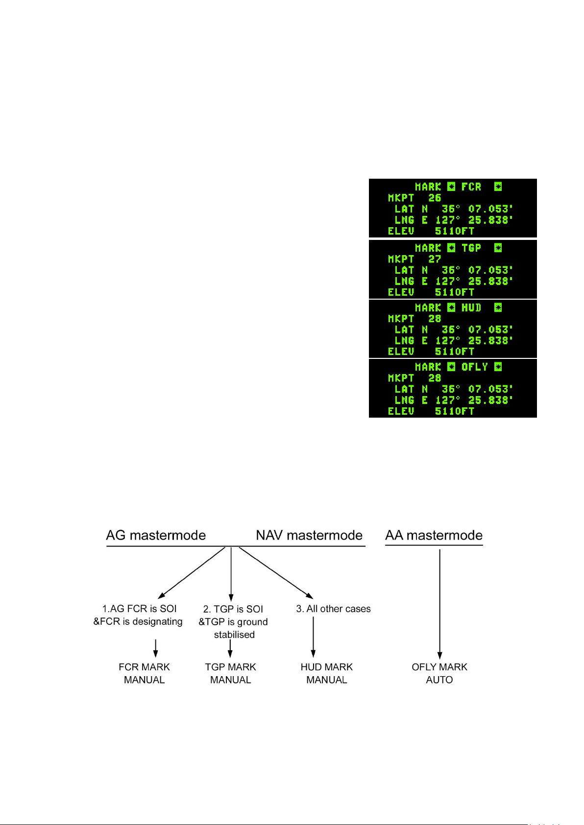
T.O. BMS1F-16CM-1 BMS 4.34 Change 2.00
BMS 4.34 Dash 1
© Red Dog 2012-2019 Page: 70
1.3.10. MARK page (7)
The MARK page is used to create markpoints. Ownship markpoints are stored in steerpoints 26-30.
Mark points can be made from 4 different systems. OFLY (Overfly GPS/INS), FCR (Fire Control
Radar), HUD (Head Up Display) or TGP (Targeting Pod). There are thus 4 submodes in the MARK
page. To toggle between the submodes use DCS SEQ. The system defaults to a specific subpage
according to master mode and Sensor of Interest (SOI) and may enable automatic markpoint
recording.
• If master mode is NAV or A-G mode and the FCR is SOI &
designating entering the MARK page will default to FCR
MARK. The first markpoint will remain blank until TMS is
moved up. At that point, the markpoint is created.
• If master mode is NAV or A-G mode and the TGP is SOI
and ground stabilised entering the MARK page will default
to TGP MARK. As with FCR, TMS up will create the
markpoint.
• If master mode is NAV or A-G mode and the FCR or TGP
are not SOI & designating or ground stabilised entering the
MARK page will default to HUD MARK. A markpoint must
be created manually by moving the HUD mark cue (HMC
– a small slewable circle appearing near the FPM in predesignate) with the cursor (HUD SOI) and moving TMS
up. The first press of TMS up will ground stabilise the
HMC and the second TMS up will save the markpoint.
HMC must be on the ground for correct implementation,
pointing at the sky will not work obviously.
• If master mode is A-A entering the MARK page will default
to OFLY MARK and an automatic markpoint will be created.
Please note: the ICP ENTR key is no longer used to create markpoints – TMS forward (TMS up)
creates markpoints.
Mode selecting (M-SEL 0 button) any valid markpoint will make it the active steerpoint.
Page 71
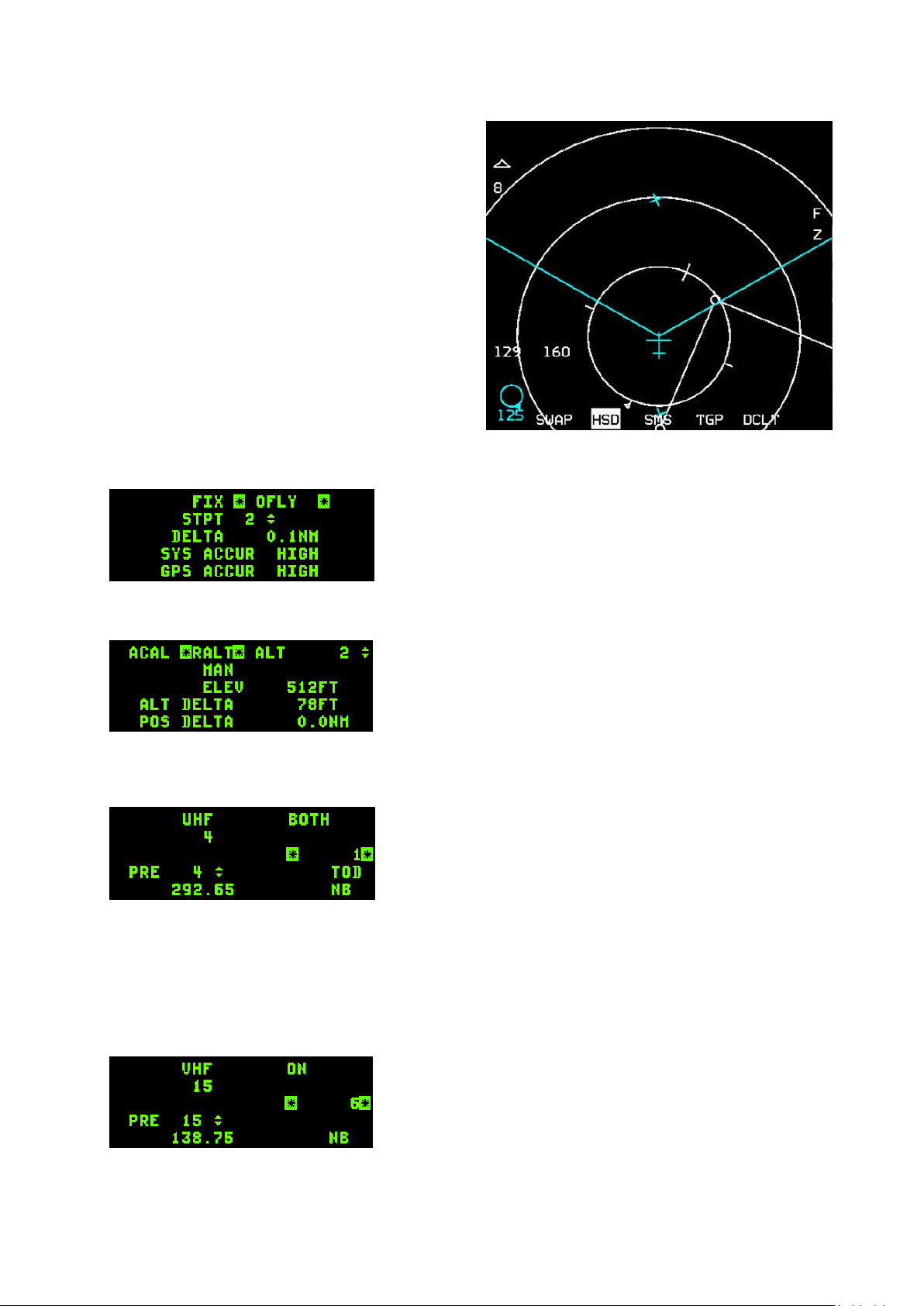
T.O. BMS1F-16CM-1 BMS 4.34 Change 2.00
BMS 4.34 Dash 1
© Red Dog 2012-2019 Page: 71
As with any type of steerpoint markpoints can be
sent over the IDM - Refer to the IDM chapter in the
TO-BMS1F-16CM-34-1-1 for further information.
Markpoints are visible on the HSD page once
created as a cyan cross.
In any MARK mode manual markpoints can be
created by setting the correct MARK subpage
according to active sensor. Move the cursor to the
desired spot and move TMS up once or twice
depending on MARK mode. If previous automatic
markpoints were recorded the markpoint rotary will
increment and the next available steerpoint in the
MARK bank will be selected. Ownship markpoints
are stored in steerpoint 26 to 30. Once #30 is filled,
the next markpoint will overwrite #26 and so on.
1.3.11. FIX page (8)
Not implemented.
1.3.12. A-CAL page (9)
Not implemented.
1.3.13. COM1 page
Pressing the COM1 ICP button brings up the UHF radio
page. The first line gives the status; in this case it’s set to
BOTH (Preset & Guard) and the frequency is 292.650 MHz.
The scratchpad is ready to receive a new frequency or the
new preset. Presets are set in the UI.
Another way to change the UHF radio is to use the ICP
NEXT/PREV ICP button to directly change the preset (note the double arrows next to the 4).
Note that the UFC UHF radio is able to listen to GUARD while transmitting and receiving on the preset
if set to BOTH. By moving the DCS to the right BOTH will be replaced by MAIN and the UHF will not
receive GUARD unless tuned to 243.0 MHz. Please refer to the BMS-Comms-Nav-book for more
information.
1.3.14. COM2 page
The COM 2 ICP button brings up the VHF radio page.
The first line gives the status of the radio, in this case it’s ON
and the set frequency is preset 15. The UFC VHF radio
cannot listen to GUARD while on a preset. It must be tuned to
121.5 MHz.
The scratchpad is ready to receive the new frequency or the
new preset.
Page 72
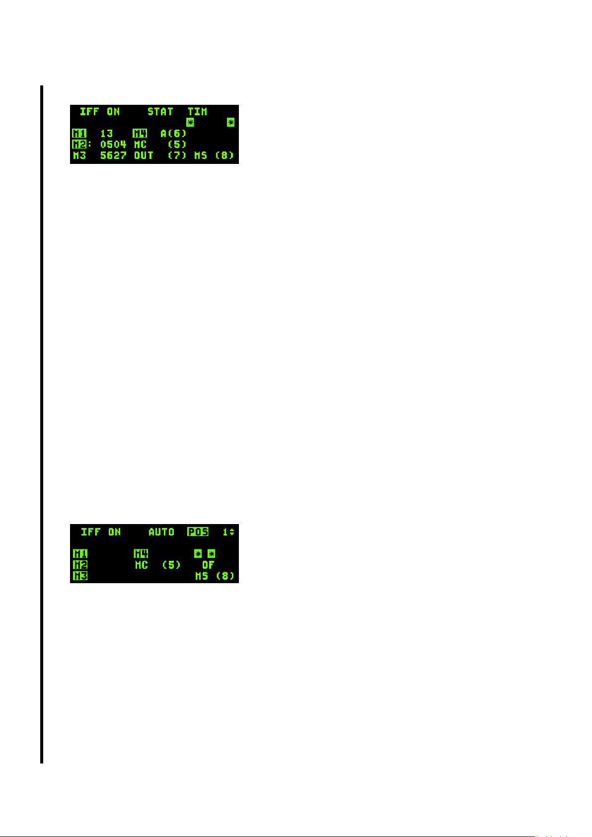
T.O. BMS1F-16CM-1 BMS 4.34 Change 2.00
BMS 4.34 Dash 1
© Red Dog 2012-2019 Page: 72
1.3.15. IFF page
IFF transponder operations are managed through 3 IFF UFC
pages: STAT (Status), TIM (Time) and POS (Position).
The default IFF page is the STAT page. Subsequent pages
are accessible with DCS right (SEQ).
IFF status can be OFF, STBY, ON, or DEGR (degraded) if the system has failed.
The last item on the first line is the TIM or POS criteria, whichever is active (see TIM and POS IFF
pages below). If both criteria are active P/T will be displayed. If neither criterion is active, nothing will
be displayed.
Active modes are highlighted. In the picture above Mode1, Mode2 and Mode4 are active; Mode3 and
ModeC and ModeS are inactive. IFF codes are given in regard to their respective mode: Mode1 code
is 13, Mode2 code 0504, Mode3 code is 5627 and Key A is currently in use for Mode4.
Selecting a mode is made through the scratchpad: enter 1 to toggle Mode1 on and off, enter 2 for
Mode2 toggling, 3 for Mode3, 4 for Mode4, 5 for Mode C and 8 for Mode S (currently not implemented)
Codes can also be entered manually with the scratchpad as follows:
Two digit encoding defaults to a Mode1 code if it’s a valid code: first digit never above 7, second digit
never above 3.
Three or Four digit encoding defaults to Mode3 provided the code is valid (between 0000 and 7777 –
no digit above 7).
The F-16 can change Mode2, unlike other aircraft. Change the Mode2 code by prefixing the 4-digit
code with a 2. For example: “2 – 4 - 6 – 5 – 0 – ENTR” will input 4650 as the M2 code.
Mode4 is encrypted and cannot be changed but can be switched between key A and key B. This is
done by entering “6 – ENTR” in the scratchpad.
Mode4 interrogation visual/audio feedback can be set with “7- ENTR” in the scratchpad. It will toggle
between OUT (no feedback when Mode4 interrogated by another aircraft), LIT (the “4” will be
highlighted on the CNI DED page – and enlarged if repeated on the HUD - when interrogated by
another aircraft) and AUD (includes LIT plus in addition an audio tone is played in the pilot’s headset if
a Mode4 interrogation not matching the set key is received).
The next two IFF subpages are used to change the IFF settings automatically according to time or
position criteria:
Press DCS SEQ to switch to the IFF POS subpage:
The IFF position page allows you to activate or deactivate
certain modes according to the position of your aircraft.
You can set 2 different position criteria by using the up and
down UFC arrow to toggle between page 1 and 2 (top right
number).This would allow you to set a different IFF setting at
fence in and at fence out for instance).
For the position criteria to be activated POS must be highlighted. Move the scratchpad to POS with
DCS up and hit 0 (M-SEL). POS will then highlight and the criteria are activated.
Position criteria do not include code changes but only toggle the different modes on/off. This is why
you do not see codes displayed on the POS page.
It is important to understand that toggling modes will depend on the current state of the mode in the
STAT page. You determine a position where modes will be toggled. Once the aircraft reaches this
position, the mode will be toggled. So if mode1, 2 and 3 are currently on and mode 4 is off as reported
by the STAT page, and you set mode1, 2, 3 and 4 to toggle in the POS subpage, then upon reaching
that position, the system will turn off mode 1, 2 & 3 and turn on mode4.
In the POS subpage you select which mode will toggle by typing “1-ENTR” to toggle Mode1 in the
scratchpad position illustrated by the picture above, type 2 to select the Mode2, type 3 for Mode 3, 4
Page 73
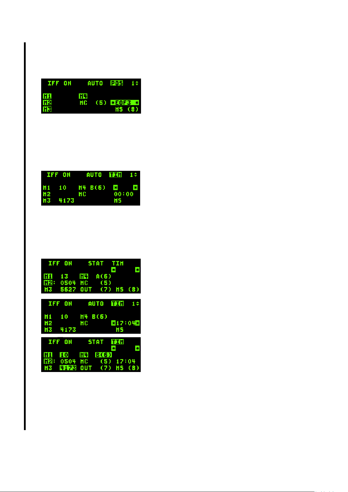
T.O. BMS1F-16CM-1 BMS 4.34 Change 2.00
BMS 4.34 Dash 1
© Red Dog 2012-2019 Page: 73
for Mode4, 5 for ModeC and 8 for ModeS (always confirm your entry with ENTR). In the picture above,
Mode1, 2, 3 & 4 are set to toggle. As you notice ModeC and ModeS are not highlighted and therefore
their state will not change upon reaching the position.
The actual position is set with the next scratchpad entry. DCS down to put the asterisks around the
“OF“. Positions are given in relation to cardinal direction and
INS steerpoints. Cardinal directions are on the ICP keypad 2
for North (the one on top), 6 for East (right), 4 for West (left)
and 8 for South (bottom). Once the scratchpad is correctly
placed input first the cardinal direction with 2, 6, 4 or 8 and
then input the steerpoint number. In the left picture I inputted
“6 3” for EAST OF steerpoint 3 (EOF3). Steerpoints are limited to 2 digits maximum but inputting one
digit is perfectly fine. Remember you can set a second position criterion by selecting page 2 of the
POS subpage with the up and down arrow.
With the above configuration, the modes 1, 2, 3 & 4 will be toggled when reaching a line EAST of
steerpoint 3.
The next IFF subpage is the Time criteria accessible with a further DCS right (SEQ).
Rather than setting position criteria to change IFF settings,
the time subpage allows pilots to set 12 different criteria
based on time. Time criteria do not impact modes, only codes
for the relevant modes. Only Mode1, Mode3 and Mode4
codes/keys can be changed with time criteria.
As with the POS subpage, time criteria are activated only when the TIM subpage is mode-selected.
Move the scratchpad to TIM with DCS up and hit 0 (M-SEL). TIM will then highlight.
Pilot can set 12 different time criteria: use the up and down arrow on the ICP to toggle between the
different criteria pages. The top right number will be updated accordingly. For instance you could set
time criteria for each hour during the next 12 hours.
Codes are inputted in the same manner as on the STAT
page: 2 digits for Mode1, 4 digits for Mode3 and toggling
between key A and key B is done by inputting “6” in the
scratchpad.
The time at which the IFF codes should change is input in the
next scratchpad position (00:00 in the picture above) which
you can select by moving the scratchpad with DCS down.
Time format must be inputted in hh:mm for 24hours. If you
want the criteria to change at 17:04 local, input “1 – 7 – 0 – 4
– ENTR”. At 17:04 local, the STAT page will report a code
change for the modes you set on the TIM page and will
display the last event change (in this case 17:04).
As you can see in the sequence of pictures on the left, the
IFF was set to change at 17:04 from Mode1:13, Mode3: 5627
and Mode4: A key to Mode1: 10; Mode3: 4173 & key B for
Mode4. Notice the code highlights on the STAT page that notify an event took place.
This all sounds complicated but bear in mind that IFF data comes preloaded into your DTC for typical
usage scenarios and pilots will not have to specify POS and TIME events from the cockpit, unless they
want to. The IFF system is set up just like the real thing though, so there is huge scope for mission
creators who want to explore its full potential.
For further information about IFF, please refer to the IFF chapter 1.16 later in this manual.
Page 74
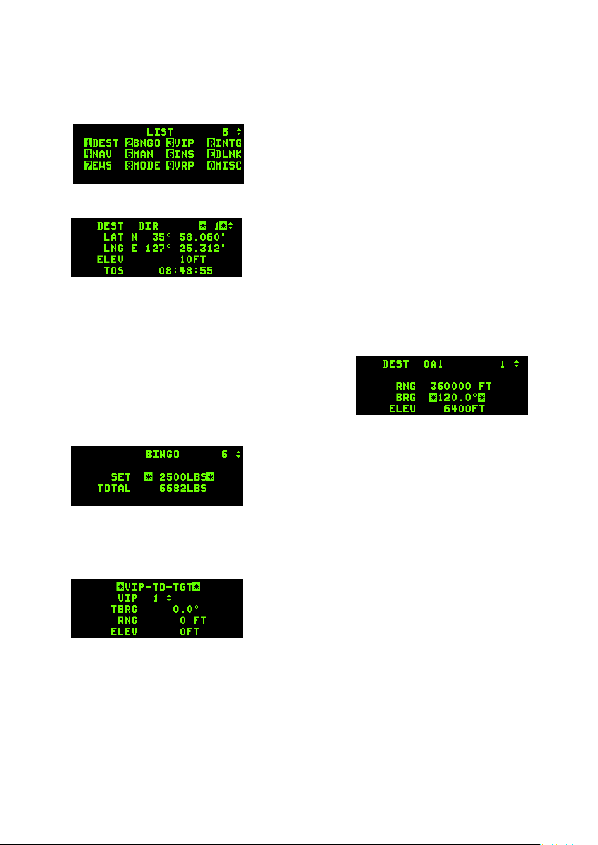
T.O. BMS1F-16CM-1 BMS 4.34 Change 2.00
BMS 4.34 Dash 1
© Red Dog 2012-2019 Page: 74
1.3.16. LIST page
The LIST page is used to access additional subpages. Each page can be accessed by pressing the
relevant ICP button: 1 for DEST, 2 for BNGO, etc. Please note: RCL, ENTR and M-SEL 0 buttons are
also used to enter INTG, DLINK and MISC subpages respectively.
Once again note the 4 and double arrows in the top right
corner, allowing the pilot to change the current steerpoint
without exiting the LIST page. It is not the case on the picture
but if VIP or VRP are mode selected they will appear
highlighted in the LIST page.
1.3.16.1 DEST page (1)
The DESTination page looks similar to the STPT page. The
main difference is that you can change any steerpoint
coordinates without direct effect on the HSD. When you
change a steerpoint with the STPT page the effects are
immediate since that particular steerpoint is active. Not so the
DEST page, which is quite handy for making steerpoints more
precise or simply for adding new steerpoints.
Please note: as with the STPT page any entered coordinate must start with the cardinal ICP key N(2),
E(6), W(4) or S(8). The scratchpad will not respond until the cardinal key is pressed.
Depressing DCS to SEQ with any steerpoint selected enters the Offset Aimpoint 1 & 2 subpages. This
lets the pilot set up two offset aimpoints for each INS steerpoint. Since BMS 4.33 you can change from
FT to KM or NM on the RNG line. DCS up until you see *FT*
(scratchpad asterisks around FT) then press any number key
to rotate through FT to KM to NM.
More information about offset aimpoints can be found in the
TO-BMS1F-16CM-34-1-1 manual.
1.3.16.2 BNGO page (2)
The BINGO page is where you input your briefed Joker/Bingo
settings. It is made up of two lines: the first one is where you
enter your Joker or Bingo setting and the second line is the
total fuel remaining on board. If the FUEL QTY knob is in
NORM the VMS will call “BINGO” upon reaching the value
set in the first line. It is good practice as a mission begins to
input the Joker value. You can then reset it to the briefed Bingo value once Joker fuel is reached.
Note the arrows next to the active steerpoint allowing you to change it as usual with the NEXT/PREV
button of the ICP.
1.3.16.3 VIP page (3)
This page is used to enter VIP settings. VIP can be calculated
manually but it is advisable to enter data given by a tool like
WDP. This data is DTC loadable and WDP can set your DTC
automatically as well. Nevertheless, should you need to input
the data manually it is possible using this page. The VIP page
must be mode-selected with the 0 (M-SEL) button for the VIP
symbology to be visible in the HUD (the text between the asterisks is then highlighted). Moving the
DCS to the right (SEQ) will enter the VIP-to-PUP page. Since BMS 4.33 you can change between FT,
KM & NM on the RNG line by moving DCS up until you see *FT* and then pressing any key as shown
above.
Page 75
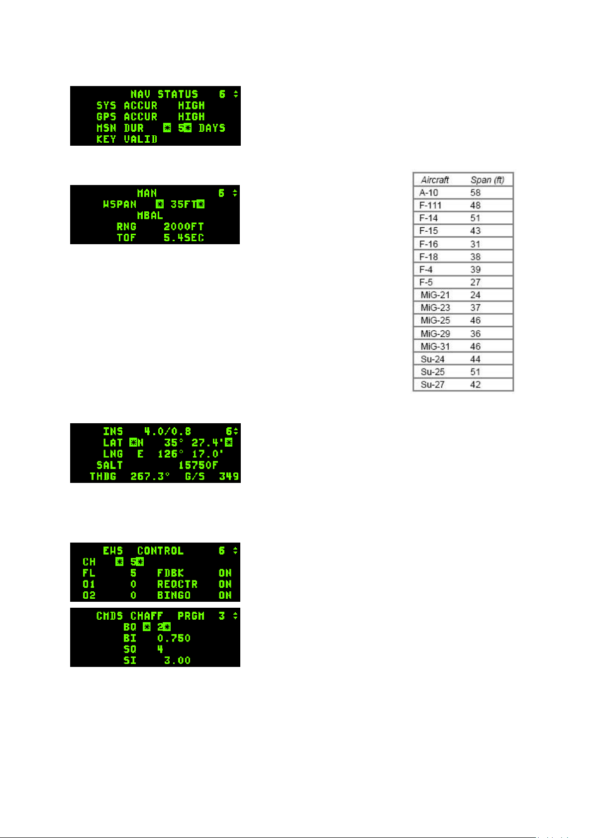
T.O. BMS1F-16CM-1 BMS 4.34 Change 2.00
BMS 4.34 Dash 1
© Red Dog 2012-2019 Page: 75
1.3.16.4 NAV page (4)
The NAV page is eye candy as it refers to the accuracy of the
navigation system which is always very good in BMS and
does not drift.
1.3.16.5 MAN page (5)
The MAN page is used to adjust
the GUN EEGS funnel width
setting for cannon firing. The
setting is entered in feet and
should match the wingspan of the
expected target. The default is 35
feet and is DTC settable (and also in WDP). On the right is a table from the
SP3 manual with the most common aircraft wingspan values.
1.3.16.6 INS page (6)
The INS page relates to the Inertial Navigation System. It is
made up of 5 lines. The first one gives status of the INS
(status 10 means fully aligned) and as always the active
steerpoint can be changed without leaving this page with the
NEXT/PREV ICP buttons. The second line gives your current
latitude and the third your current longitude. The next line
gives your barometric altitude and the last line your true
heading and groundspeed. This last bit of information is very useful when taxiing as it is the only way
to see information about your taxi speed.
1.3.16.7 EWS page (7)
The Electronic Warfare System page is where you setup your
EWS.
Normally all these settings are in your DTC but you can also
reprogram them on the fly through this page. Programming is
only possible when the CMDS mode knob is placed in STBY.
The main section of the EWS page allows changes to the
chaff and flare bingo settings and to enable or disable the
REQCTR (request to counter), FDBK (feedback) and
“BINGO” VMS calls.
Moving DCS to SEQ displays the expendable category (chaff
then flares) for manual programming (programs 1 to 6). The
arrows now designate the possibility to toggle among the 6 available CMDS programs to reprogram
them. You toggle from the chaff page to the flare page using DCS SEQ. For each program and each
expendable type you are allowed to set the Burst Quantity (BQ), Burst Interval (BI), Sequence quantity
(SQ) and Sequence Interval (SI) just like in the DTC. For further information, please refer to the TOBMS1F-16CM-34-1-1 ALE-47 COUNTERMEASURES DISPENSER SET chapter.
Page 76
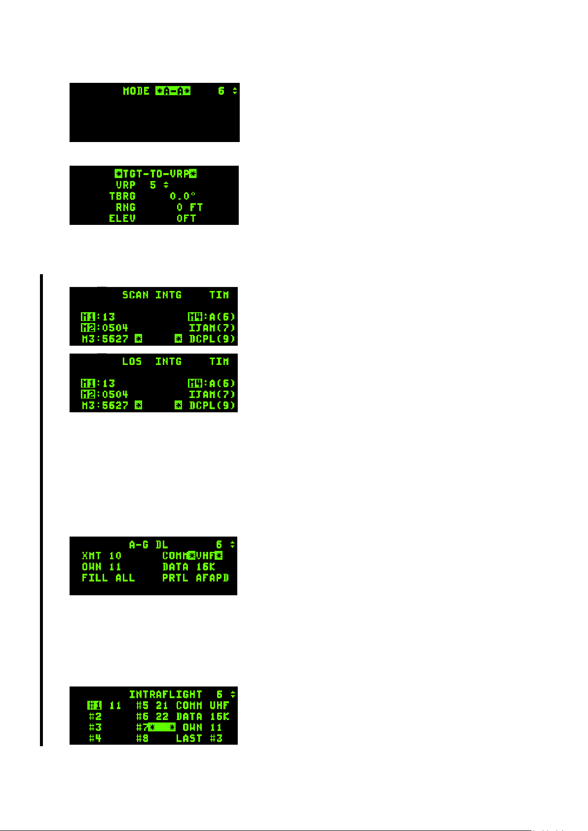
T.O. BMS1F-16CM-1 BMS 4.34 Change 2.00
BMS 4.34 Dash 1
© Red Dog 2012-2019 Page: 76
1.3.16.8 MODE page (8)
The MODE page provides an alternative way of changing the
Master Mode without using the ICP buttons. Move the DCS
to SEQ to toggle the Master Mode and mode select it with the
M-SEL 0 key to make it active. NAV mode defaults when
none of the others (A-A or A-G) are mode selected.
1.3.16.9 VRP page (9)
This page is used to enter VRP settings. VRP can be
manually calculated but it is advisable to enter data given by
a tool such as WDP. This data is DTC loadable and WDP can
set your DTC automatically as well. Nevertheless, should you
need to input the data manually it is possible to do so using
this page. The VRP page must be mode selected (with the MSEL 0 button) for the VRP symbology to be visible in the HUD (the data between the asterisks is then
highlighted). Moving DCS to the right (SEQ) will enter the VRP-to-PUP page. DCS RTN exits back to
the CNI page.
1.3.16.10 INTG page (RCL)
The INTG pages (now active in 4.34) are relevant to IFF
interrogator settings. There are two subpages, both with the
same structure yet independent from each other. One is for
SCAN and one for LOS (Line of Sight).
SCAN and LOS page can be toggled with DCS right (SEQ).
They display the active interrogator mode (active modes are
highlighted) and the corresponding code for each mode. In
modes 1/2/3 the interrogator does not send any data, it
compares the received codes with the one inputted and if they
match, the returned answer is considered friendly.
Codes can be changed with the same method as in the IFF
STAT page: 2 digits for Mode1, 4 digits for Mode3 and 5 digits
(always starting with 2) for Mode2. Mode4 has no code but it is important that the active key is valid as
a transponder will not respond to an invalid key query.
Modes can be enabled or disabled in the same way as the STAT page as well, 1 toggles M1, 2 M2, …
IJAM is not implemented and is relevant to IFF jamming.
Entering “9 – ENTR” in the scratchpad couples or decouples the SCAN/LOS interrogator code to/from
the transponder codes. When coupled, all changes made manually or through the change criteria
(POS/TIM) to the IFF transponder pages will be automatically copied to the IFF interrogator pages.
If decoupled, interrogator pages will not reflect any changes made on the transponder pages.
1.3.16.11 A-G DL page (ENTR)
The Data Link pages are used to set your in-flight data-link
settings. You can change the XMIT (transmit) address, the
OWN address, the FILL and the COMM options.
The XMIT address is your ownship IDM address category.
OWN is your specific address within that category.
The FILL option determines whether the system stores (ALL)
or ignores (NONE) all received data-link steerpoints. When the FILL option is set to ALL the received
steerpoints are stored in the steerpoint databank between #71 & #80. When more than 10 IDM
steerpoints are received position #71 is overwritten and so on.
When option NONE is selected the system doesn’t store received markpoints and the pilot gets no
HUD or VMS messages. The COMM option toggles (with any ICP number key) between VHF or UHF
for A-G datalink (Intraflight will always use the opposite radio to A-G DL).
If DCS is moved right to SEQ the INTRAFLIGHT subpage is displayed. This is where other flight IDM
addresses can be entered to enable A-A data-link with them.
Ownship (#1) can now be changed, though you will typically
use the first column for your own flight and the second column
for extra flights in your package. Simply enter the IDM
addresses of flight members you wish to add. Example below:
Your flight IDM is 20 (21-22-23-24), Strike flight IDM is 10 (11-
Page 77
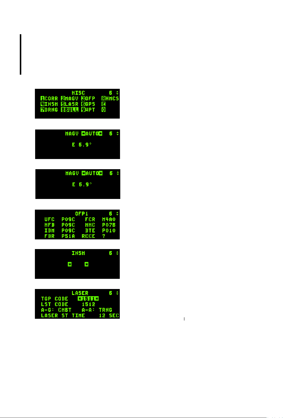
T.O. BMS1F-16CM-1 BMS 4.34 Change 2.00
BMS 4.34 Dash 1
© Red Dog 2012-2019 Page: 77
12), SEAD IDM is 30 (31-32-33-34).
The first column is already full with your flight IDM and you only have 4 slots free in the second one.
One possible compromise could be to enter the Strike flight (11-12) in positions #5 & #6 and enter the
Lead and Element Lead of the SEAD flight (31-33) in positions #7 and #8. This is left to the pilot’s
discretion but it is important to set multi-package IDMs correctly to maintain good SA during COMAO.
Please note A-A IDM radar tracks are only received from IDM addresses in the first (left) column.
For further information please refer to the TO-BMS1F-16CM-34-1-1 IDM chapter.
1.3.16.12 MISC page (0)
The MISC page leads to yet another list of submodes. The
principles of operation are the same as the LIST page:
depress the corresponding button listed on the MISC page to
access the subpage.
1.3.16.12.1. CORR page
Correction page is not implemented.
1.3.16.12.2. MAGV page
Displays the actual Magnetic Variation at this aircraft location.
It would be used to correct INS navigation errors should they
happen in BMS. At the moment this is done automatically by
the code.
1.3.16.12.3. OFP page
Operational Flight Program page is not implemented.
1.3.16.12.4. INSM page
Inertial Navigation System Memory page is not implemented.
1.3.16.12.5. LASER page
This page is used to set up the Laser system. It is made of 4
lines.
The first sets the TGP code which must match the targeting
laser pulse code of the weapon (set in the UI LOADOUT
screen). If the TGP CODE does not match the weapon code
the GBU will not guide and will fall ballistically. It is therefore
possible to conduct buddy lasing by inputting the weapon code of your wingman’s bombs. The second
line sets the Laser Spot Track code. The third line toggles the laser from Training to Combat mode
with any ICP button. The fourth line sets the laser timer. The targeting laser is fired for final weapon
guidance automatically before impact and is DTC loadable. It’s also more realistic in 4.34; you are now
advised to set it to 10 or 12 seconds for Paveway II bombs and perform manual lasing for Paveway III
bombs and moving targets as necessary. For further information please refer to the TO-BMS1F16CM-34-1-1 SNIPER XR ADVANCED TARGETING POD chapter.
Page 78
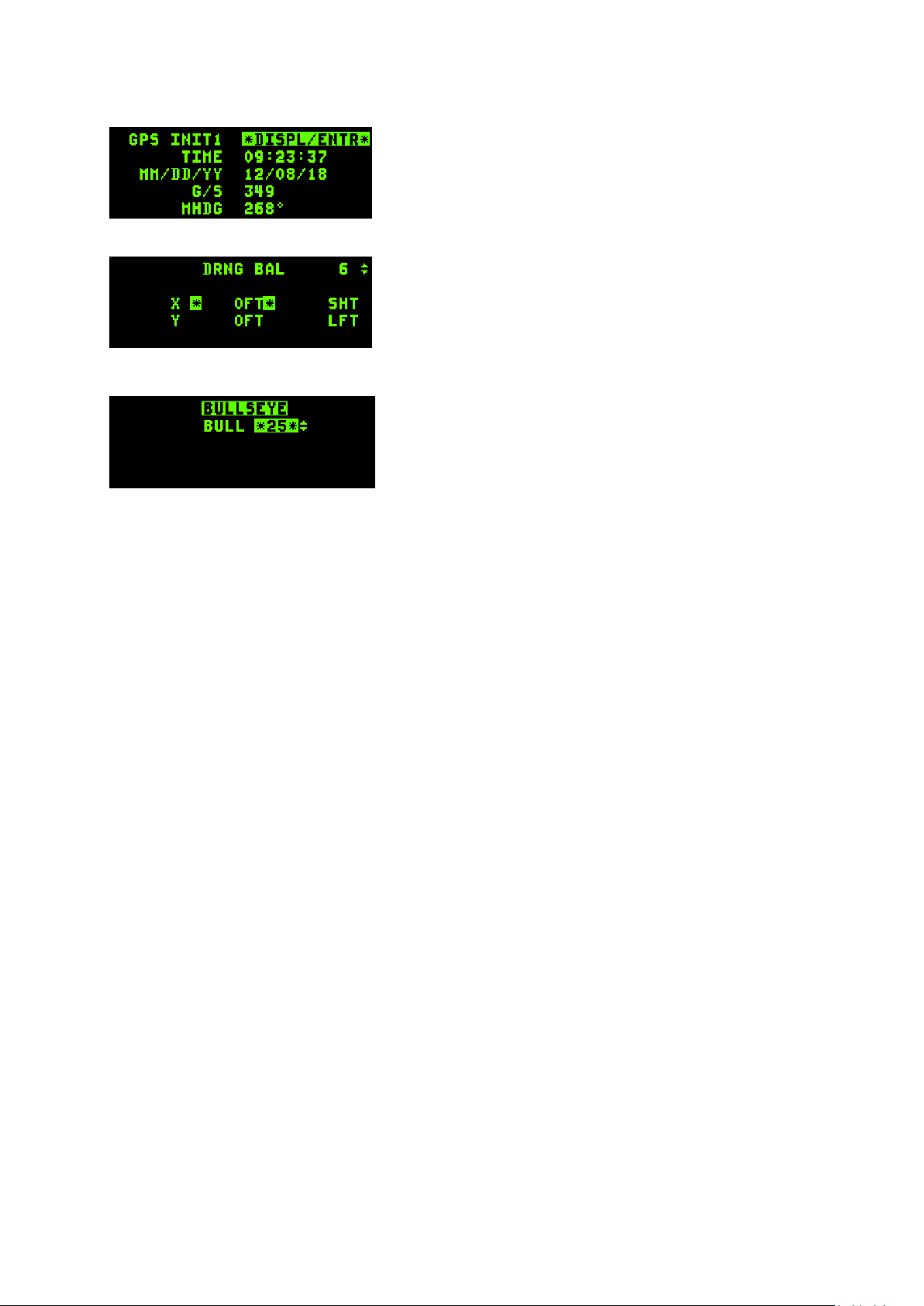
T.O. BMS1F-16CM-1 BMS 4.34 Change 2.00
BMS 4.34 Dash 1
© Red Dog 2012-2019 Page: 78
1.3.16.12.6. GPS page
Displays information about the GPS system.
1.3.16.12.7. DRNG page
Not implemented.
1.3.16.12.8 BULLSEYE page
This is where you manage system Bullseye.
Bullseye is by default assigned to STPT #25 but you can
change it to any steerpoint (up to #25) by using the
PREV/NEXT ICP button.
Display of Bullseye information changes depending on
whether BULLSEYE is mode selected or not. Mode selection is toggled by pressing M-SEL 0 when the
scratchpad asterisks surround the ‘BULLSEYE’ text and is on by default.
Bearing and range to Bullseye is displayed in the bottom left corner of the HUD when Bullseye is
mode selected. When it is not mode selected you will have no bearing and range indication to
Bullseye in the HUD.
In the MFDs (FCR and HSD pages) bearing and range information of the cursor position is shown
relative to the Bullseye position when BULLSEYE is mode selected and relative to the active
steerpoint when BULLSEYE is not mode selected. This may vary according to block, with newer
blocks always displaying the flight director symbol, even with BULLSEYE mode selected.
The Bullseye symbol & circle is not displayed on the MFDs when BULLSEYE is not mode selected.
Instead a waterline flight director symbol relative to the current active steerpoint is displayed.
Please note: when distance to Bullseye is more than 99Nm the distance is not displayed inside the
Bullseye circle (two digits only) on the MFD page.
So, to be able to maintain good Situational Awareness when calling out contacts with Bullseye bearing
and range you need to have BULLSEYE mode selected, which is the default setting.
Page 79
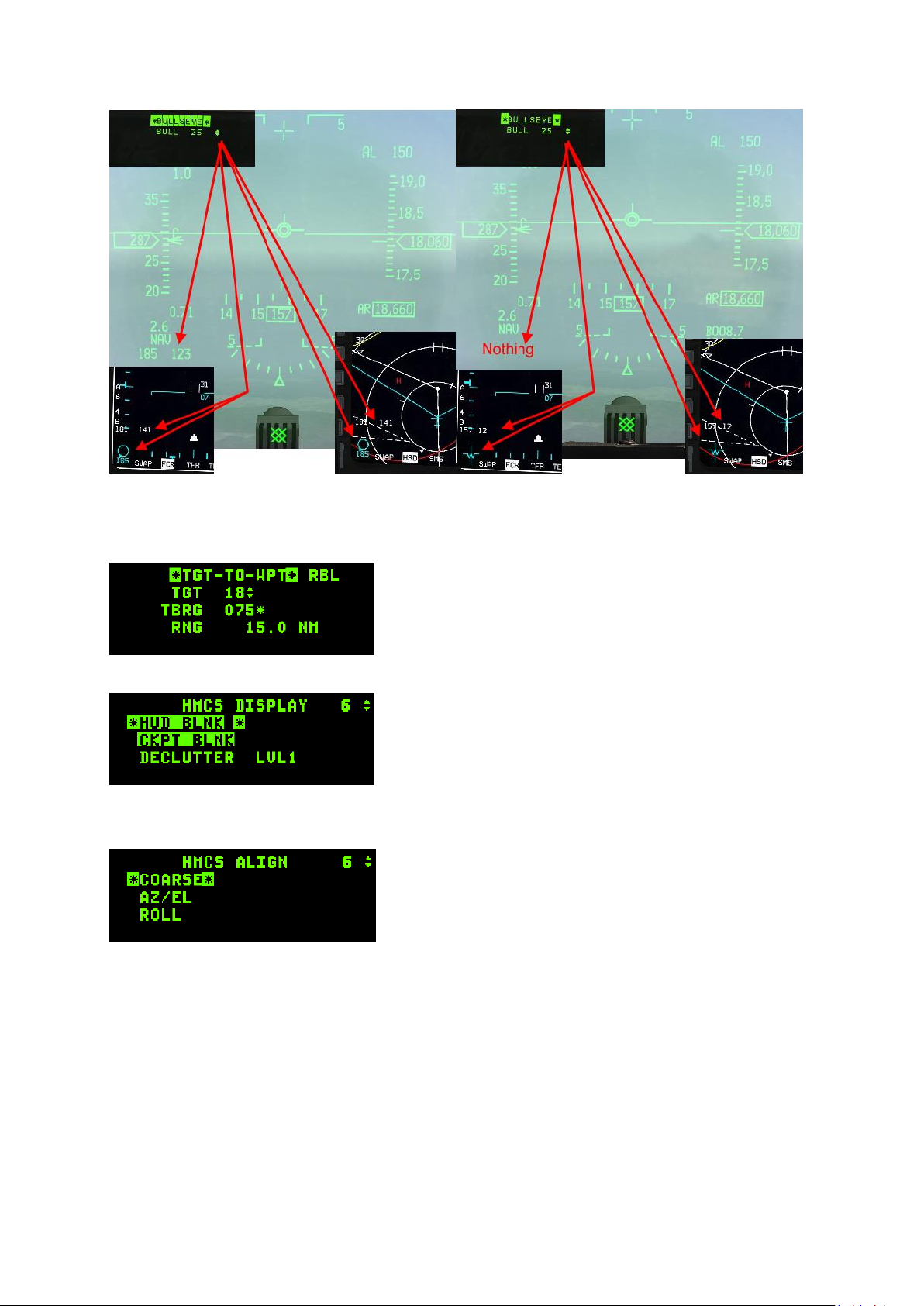
T.O. BMS1F-16CM-1 BMS 4.34 Change 2.00
BMS 4.34 Dash 1
© Red Dog 2012-2019 Page: 79
The left picture shows the HUD, FCR and HSD Bullseye symbols when BULLSEYE is mode selected;
the right picture shows the same elements when BULLSEYE is not mode selected.
1.3.16.12.9. WPT page
The TGT-TO-WPT page is made to control Harpoon
waypoints in RBL mode. Settings can’t be changed when
accessed from the LIST page.
1.3.16.12.10. HMCS page
The HMCS (Helmet Mounted Cueing System) display page
allows the pilot to control the HMCS (on supported aircraft).
The first line enables HUD blanking when mode selected.
The HMCS will not be displayed when looking at the HUD.
The second line enables blanking the HMCS when the pilot
looks inside the cockpit.
The third line allows a selection of three levels of de-clutter for the HMCS displays. Highlight that line
with DCS down and hit any ICP secondary button to change from level 1 to level 2 to level 3 to level 1.
If you depress the DCS to SEQ while in the HMCS display
page another subpage will be displayed, though it is not
implemented at this time.
Refer to the HMCS chapter in the TO-BMS1F-16CM-34-1-1
for further information about the HMCS displays &
capabilities.
Page 80

T.O. BMS1F-16CM-1 BMS 4.34 Change 2.00
BMS 4.34 Dash 1
© Red Dog 2012-2019 Page: 80
1.3.17. DRIFT C/O switch
The DRIFT C/O switch is a three-position switch with a momentary position to WARN RESET.
Upper and middle positions manage the DRIFT of the flight path marker according to winds. The
centre position, labelled NORM takes winds into account and lets the FPM drift to the side according
to crosswinds, giving you a visual cue of beta angle (sideslip crabbing into the wind).
In the NORM position the FPM indicates where in 3D space the aircraft will fly towards with the current
flight conditions and no additional control inputs. In other words if you hold what you have on the
controls the FPM will show you where the jet will ultimately end up.
This is particularly useful for landing because it lets you picture the wind visually so you can
compensate automatically.
On the other hand it may be an annoyance at high altitude with strong winds (which may throw the
FPM off the edges of the HUD) and the upper position labelled DRIFT C/O maintains the FPM in the
centre of the HUD regardless of winds. The switch should be placed to NORM before landing.
The lower momentary position is labelled WARN RESET and is used to reset the HUD WARN
message.
1.3.18. The ICP Thumbwheels
The top left is labelled SYM and used for HUD brightness. The wheel has an ON/OFF switch at the
beginning of its travel, which is where the HUD is powered up.
The one labelled DEPR RET (top right) lets the pilot manage the backup bombing mode.
The brightness (BRT) wheel (bottom left) controls FLIR brightness on the HUD. Use this wheel to
display the FLIR image on the HUD. Its effect will only be noticed when the FLIR is operational.
The bottom right wheel (CONT) is not implemented at this time.
It is possible to control the implemented wheels with the mouse, keystrokes or an analogue axis.
Page 81
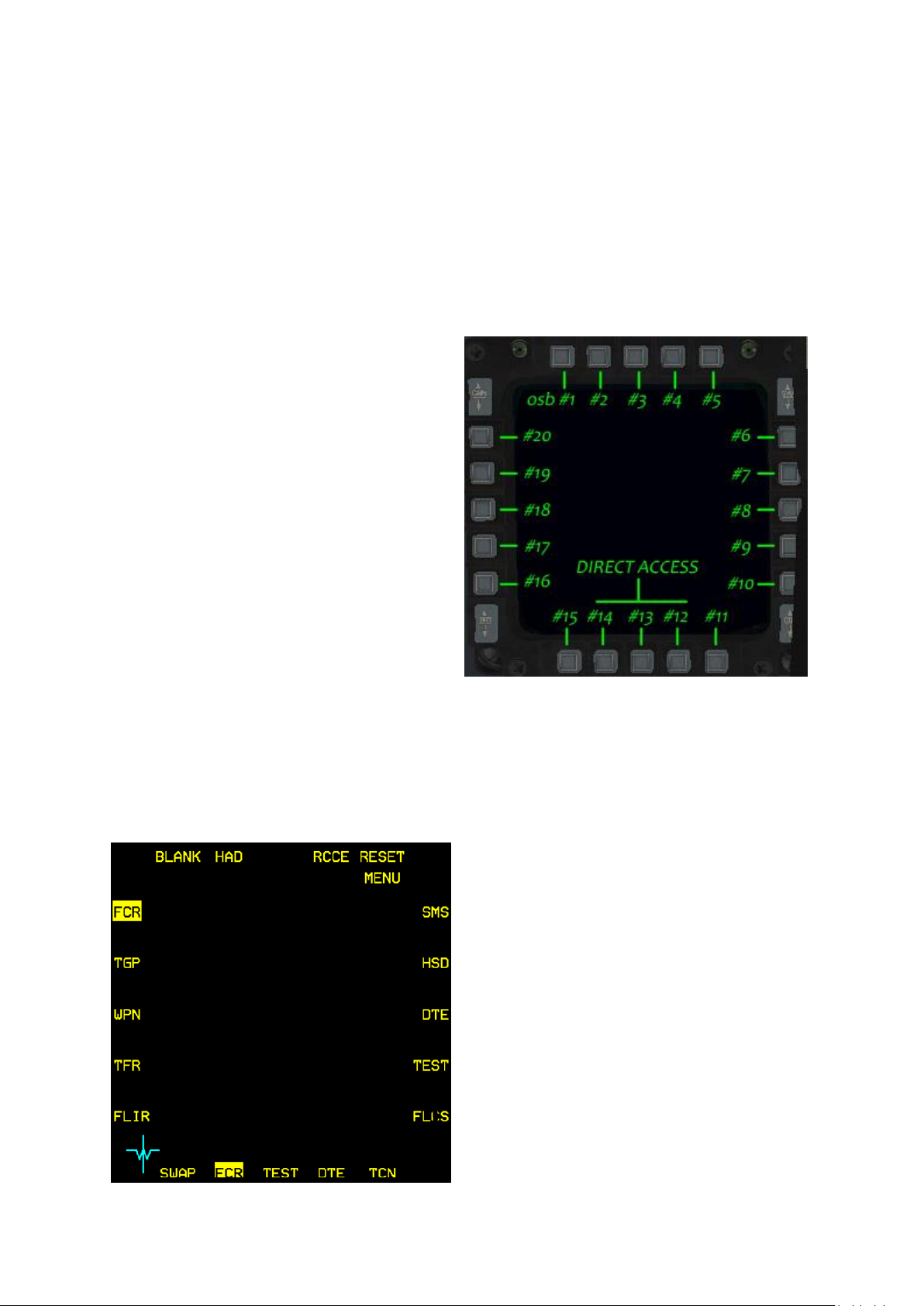
T.O. BMS1F-16CM-1 BMS 4.34 Change 2.00
BMS 4.34 Dash 1
© Red Dog 2012-2019 Page: 81
1.4 MULTI FUNCTION DISPLAYS
The MFDs are the two displays situated on the front dash featuring 20 pushbuttons and four rocker
switches on each. Both displays are independent. MFDs are powered by the MFD switch on the
AVIONICS POWER panel on the right side console.
The push buttons are called Option Selection Buttons (OSB) and are numbered from 1 to 20, starting
at the left button of the top row and moving clockwise to the top button of the left row.
The function of the button changes according to the displayed page and the button’s legend is
displayed next to the button.
The top, left and right rows of buttons are
typically assigned customized functions
depending on the page being displayed. By
contrast, the bottom row (OSB 11 to 15) operates
more or less the same way regardless of page
format:
• OSB #15 is always a SWAP button that
will swap over the left and right displays.
OSB #11 is usually a declutter option.
The only page where OSB #11 is not
used for declutter is the SMS page where
OSB #11 selects the S-J (Selective
Jettison) master mode.
• The three centre OSBs (#12, #13, #14)
are Direct Access (DA) buttons and
provide direct access to the DTC saved
MFDs displays according to master
mode. Up to three pages for each MFD
may be assigned to the DA buttons for
each master mode. The displayed page
format has its DA mnemonic highlighted. These are easily toggled by pressing the
corresponding direct access OSB button or they can be cycled even faster with the HOTAS
buttons: DMS right for the right MFD and DMS left for the left MFD. Please note you cannot
have the same page displayed on both MFDs at the same time, so if you try to display the
FCR on the right MFD while it is already being displayed on the left MFD the FCR will simply
be taken from the left MFD leaving an empty DA slot where it was originally assigned.
1.4.1. Menu page
Although it is advised to set the three most
required MFD pages for each master mode in the
DTC it is also possible to set them in the cockpit
by modifying the direct access button setting,
while the desired master mode is engaged.
To do so, first set the desired master mode, then
display the page you want to change (its
mnemonic is highlighted). Press the DA button
that is highlighted and the MFD displays the
MENU page. From there simply select the new
page you want to have accessible and the new
page mnemonic appears on the direct access row,
replacing the previous one. You can now easily
toggle it with the DMS HOTAS button.
As you can see from the left image, the default
MFD colours changed on some aircraft in 4.34
(though you can customise them with the Avionics
Configurator). Note also the new entry: the backup
TACAN page (see § 1.4.17 TACAN page).
Page 82
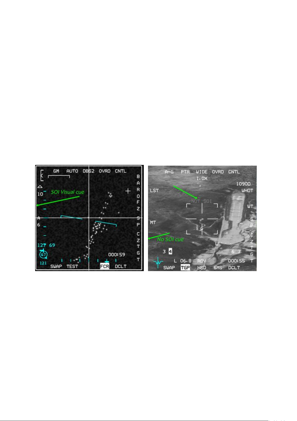
T.O. BMS1F-16CM-1 BMS 4.34 Change 2.00
BMS 4.34 Dash 1
© Red Dog 2012-2019 Page: 82
The Menu page is the link between all subpages. It is displayed when the DA button is depressed
while that particular page is already displayed (pressing FCR when FCR is already being displayed for
instance).
You can thus access any subpages in any master mode from this page: Stores Management System
(SMS), Horizontal Situation Display (HSD), Data Transfer Equipment (DTE), TEST page, FLCS page,
Forward Looking Infrared (FLIR) page, Terrain Following Radar (TFR), Weapon (WPN) page,
Targeting Pod (TGP) page; Fire Control Radar (FCR), BLANK page, HARM Attack Display (HAD)
page, Reconnaissance (RCCE) and RESET page.
1.4.2. Sensor of Interest (SOI)
You will need to work on one MFD rather than the other one sometimes. To let the system know
where you are focusing your attention you need to use the Sensor of Interest mechanisation. Imagine
the following example: the FCR is SOI and set on the left MFD and the HSD is on the right. You would
like to delete a threat ring on the HSD but if you move your cursor the captains bar moves both in the
HSD and the FCR. To tell the system that you want to work specifically on the HSD, you need to make
the HSD SOI. To do so, simply move the DMS (Display Management Switch) on your HOTAS down.
The SOI toggles from one MFD to the other. The visual cue for MFD SOI is the big square box drawn
outside the OSB labels. If a MFD is not SOI the text NOT SOI is displayed in the centre, reminding the
pilot that this display is not the Sensor of Interest.
Above, the FCR on the left MFD is the SOI and displays the large square SOI cue around the edge of
the display. The TGP on the right MFD does not display the SOI cue and instead shows the NOT SOI
cue in grey in the middle. Only one MFD can be SOI at a time.
DMS up selects the HUD as SOI (if the HUD is in a mode allowing SOI). In this case the SOI cue is an
asterisk shown in the top left corner of the HUD. DMS down toggles SOI from one MFD to the other.
Since BMS 4.33 slewing your ground cursor position (System Point of Interest or SPI) will effectively
slew your current steerpoint by adding a system delta to all steerpoints. All NAV and weapon delivery
steering and symbology, including the great circle steering cue (tadpole) will be referenced to the
amended steerpoint(s). The CZ mnemonic will be highlighted in aircraft with the Nav EGI upgrade if a
system delta exists (i.e. SPI slew).
Pilots should use the following routine to revert the system solution back to the original navigation
solution if cursor slews have been made: TMS down - Cursor Zero - Wide Field of View (OSB#3).
This habit should be developed after each cursor slew phase and at each IP if cursor slews have been
made.
Please see the chapter on SPI Management in the TO-BMS1F-16CM-34-1-1 for more details.
Page 83
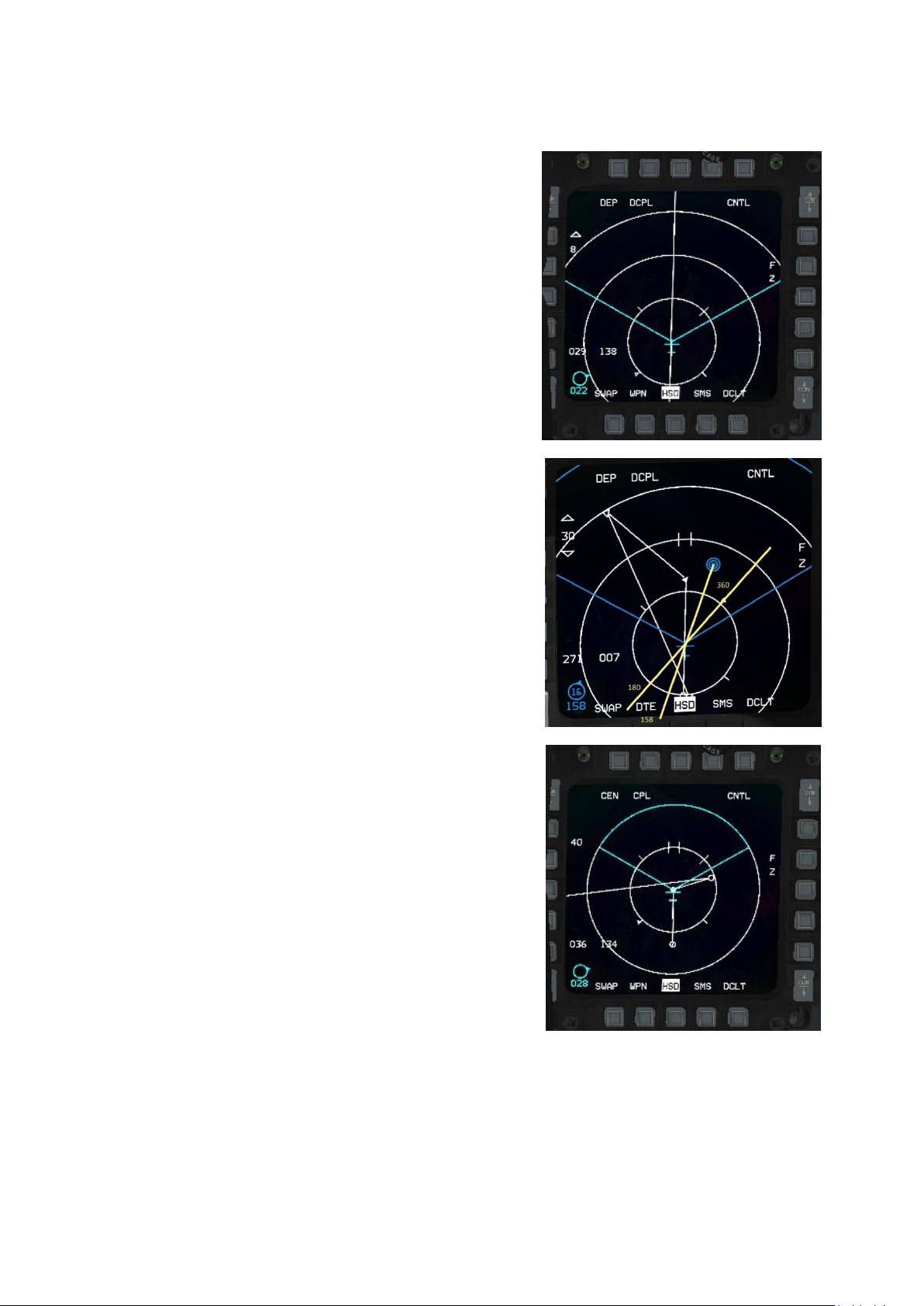
T.O. BMS1F-16CM-1 BMS 4.34 Change 2.00
BMS 4.34 Dash 1
© Red Dog 2012-2019 Page: 83
1.4.3. HSD page
The Horizontal Situation Display page provides a god’s eye
view around your aircraft with information such as your radar
cone, concentric range circles, radar cursor position,
bullseye position (or bearing and range), INS flight plan with
steerpoints, lines, PPTs (Pre-Planned Threat points) and
their programmed range rings, IDM information and so on.
OSB #19 and #20 are used to change the HSD range. In the
image on the right only OSB #20 is available to increase the
range. Note the absence of a down arrow next to OSB #19
as the HSD is at its minimum decoupled range of 8 Nm.
The concentric ranges circles are dependent on the current
range but you will always have three of them in depressed
mode, with the last one being at the set range shown at the
upper left. The closest one is thus at 1/3 of that range and
the middle one at 2/3 of the range.
The inner HSD ring is divided by 4 cardinal marks. The small
flag indicates North. The longer line indicates South and the
two smaller lines point to East and West. These cardinal
directions are useful to determine your direction from the
HSD itself. They are also very helpful with bullseye situation
awareness. By joining the North and South pointer you draw
a reference line that can be used to quickly identify bearing
from the bullseye calls. In the right example, ownship
position is 158°from bullseye 16Nm and the radar cursor
position is 271°, 7Nm from Bullseye.
OSB #1 is labelled DEP (Depressed) and when pressed
toggles to CEN for Centred.
In DEP ownship is pictured below the centre of the MFD one
quarter of the way up from the bottom and visibility is better
in front of the aircraft than to the rear. When CEN is selected
ownship is placed in the middle of the display and the
visibility is equal to the front or behind own ship. Please note,
ranges are also different in DEP or CEN. The minimum range
for DEP is 8Nm, while you can go as low as 5 Nm in CEN.
CEN mode also matches the FCR ranges better.
OSB #2 is labelled DCPL (Decoupled) and when depressed
toggles to CPL (Coupled) which ties the HSD to the FCR
range. In CPL mode OSB #19 and #20 are inhibited (no
arrows displayed) and the HSD will change scale according
to the FCR scale (range).
To maintain a good correspondence between the HSD and
the FCR (which helps SA) it is advisable to work with the
HSD in CPL and CEN modes. This ensures that both ranges are the same and move together
according to the FCR range.
Page 84
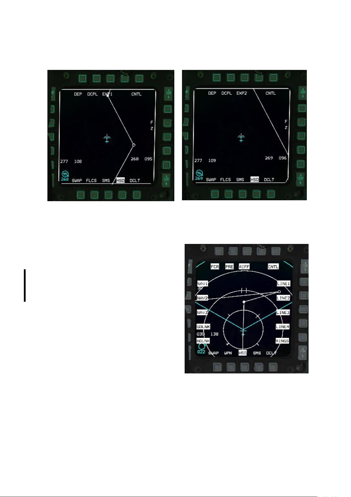
T.O. BMS1F-16CM-1 BMS 4.34 Change 2.00
BMS 4.34 Dash 1
© Red Dog 2012-2019 Page: 84
OSB #3 is labelled NORM/EXPAND and changes the FOV of the HSD when the HSD is SOI. This can
also be done using the HOTAS pinky switch. This option is invisible when the HSD is not SOI. The
EXP mode has two levels: EXP1 and EXP2
OSB #5 is the CNTL (Control) page for the HSD. When depressed a series of options are displayed
on most buttons. Highlighted options are currently active and therefore will be displayed on the HSD.
When the corresponding OSB is depressed the option becomes inactive (not highlighted) and the
related symbology is blanked from the HSD.
Display (on/off) options are:
FCR: FCR cone and ghost radar cursors
PRE: pre-planned steerpoints and their threat rings
AIFF: IFF response symbols (now implemented)
LINE1: DTC line 1 (steerpoints 31 to 36)
LINE2: DTC line 2 (steerpoints 37 to 42)
LINE3: DTC line 4 (steerpoints 43 to 48)
LINE4: DTC line 4 (steerpoints 49 to 54)
RINGS: concentric range rings from ownship
ADLINK: Air to Air datalink information
GDLINK: Air to Ground datalink information
NAV1, 2 & 3: INS flight plan but only NAV1 is
implemented in BMS for the whole INS flight plan
Exit the Control page by pressing OSB #5 CNTL.
Please note the direct access buttons are displayed
as usual OSB #11 remains the DCLT option and
OSB #15 remains the SWAP option.
OSB #7 is labelled FZ on the main HSD page format and freezes the display at the current world
position and orientation of the ownship.
The aircraft now moves around with the world position fixed on the MFD (ownship is free to fly around
and off the HSD) instead of the world moving with reference to the aircraft. Pressing the FZ button
again unfreezes the HSD world position.
Page 85
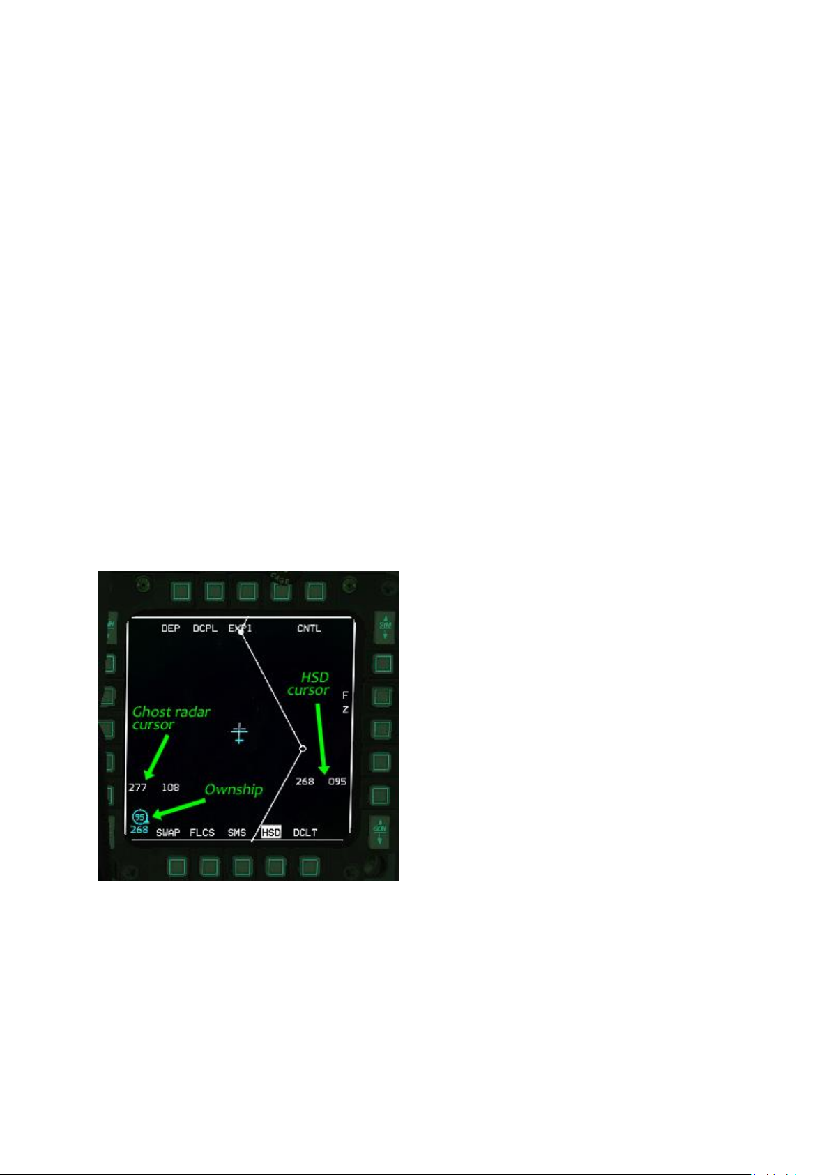
T.O. BMS1F-16CM-1 BMS 4.34 Change 2.00
BMS 4.34 Dash 1
© Red Dog 2012-2019 Page: 85
BOTTOM ROW is displayed as usual with declutter and swap buttons (#11 & #15) and the direct
access buttons between them.
HSD cursor
When the FCR and the HSD are both displayed and the FCR is SOI the HSD displays the ghost radar
cursors moving within the radar scan zone depicted on the HSD.
When the HSD is made SOI the ghost radar cursor is replaced with the HSD cursor which is shown as
a cross. Any subsequent cursor movement will then move the HSD cursor and not the radar cursor.
The HSD cursor can be used to select new steerpoints of interest and toggle on/off specific threat
rings on PPTs displayed on the HSD. TMS up over a HSD steerpoint makes that steerpoint the new
steerpoint of interest, TMS down on a PPT will deactivate the associated threat ring. This cursor has
its own bullseye reading on the right side of the HSD, between OSBs #9 and #10.
Cursor bumping
To change the range of the HSD you can use OSBs#19 & #20 in DCPL mode or change the FCR
range in CPL mode.
There is a third way to change the HSD range (which is also valid for the FCR) that is called cursor
bumping. It is done by moving the cursor towards the upper or lower edge of the display. When the
cursor gets close the range will automatically change up or down accordingly. This is done mainly on
the FCR because most of the time the FCR is SOI, but it also works on the HSD when it is SOI.
If the HSD is in CPL mode the first hit on any top or bottom edge will switch the HSD to DCPL mode
and subsequent hits will change the range.
Bullseye symbols
There are many different bullseye symbols on the HSD page.
You can find bearing and range information from Bullseye for your ownship, the ghost radar cursor,
and the HSD cursor when it is displayed.
Ownship bullseye information is always displayed in the bottom left corner of the HSD. It is the same
information that is displayed in the bottom left
corner of the HUD when Bullseye is mode selected
in the UFC (LIST-MISC-BULL page). If Bullseye is
not mode selected this symbol is replaced by a mini
flight director relative to the active steerpoint.
Ownship Bullseye is coloured cyan with the bearing
below the circle and the distance in the circle.
Distance is limited to 2 digits, so if Bullseye is
further away than 99 Nm the circle is empty.
Ghost radar cursor Bullseye information is
displayed in white on the left side of the MFD. The
first number is bearing in degrees and the second
number is distance in Nm.
HSD cursor Bullseye readout if displayed (HSD
SOI) is on the right side of the screen and has the
same structure as the ghost radar cursor
information, i.e.: bearing then distance.
Page 86
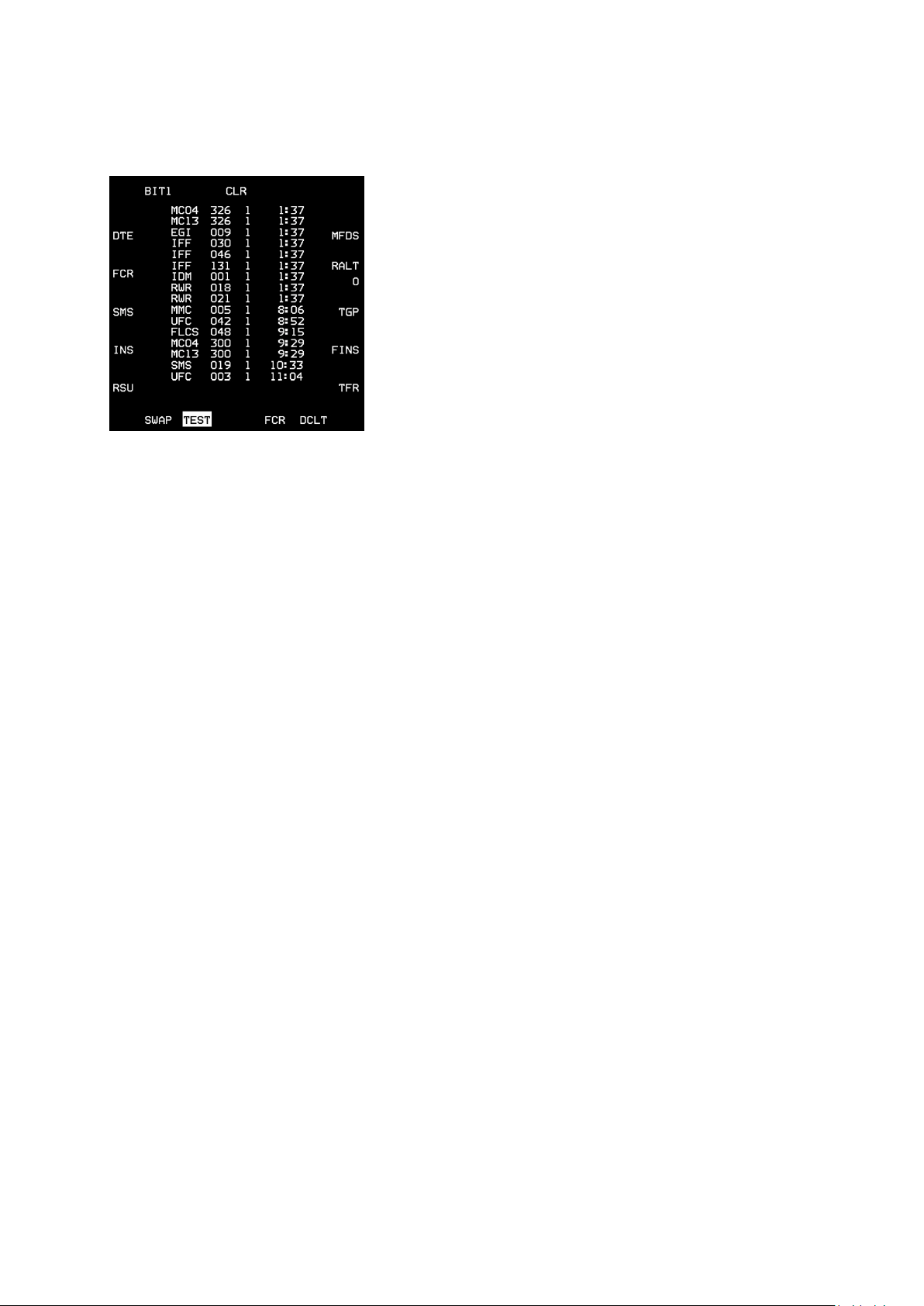
T.O. BMS1F-16CM-1 BMS 4.34 Change 2.00
BMS 4.34 Dash 1
© Red Dog 2012-2019 Page: 86
1.4.4. TEST page
The TEST page shows various Built-In Tests (BIT). BIT1 and
BIT2 display the maintenance fault list (MFL) encountered
during a flight. Each fault encounter logs the following:
1. Subsystem (same as on PFL) where the fault occurred
2. Test number that failed
3. Number of failures of that subsystem
4. Time (since FCC power up) the first fault occurred
Two pseudo-faults are always recorded; the take-off time
(TOF) and landing time (LAND). TOF is recorded whenever the
airspeed reaches 120 kts with the gear up. LAND is recorded
whenever the gear is down and airspeed is less than 80 kts.
Pressing the CLR button will clear the fault list and launch a
fault survey. A maximum of 17 faults (including the two pseudofaults) may be recorded. If more than 17 faults are present the oldest (which occurred first) will be
replaced by the newest one. After the flight pilots can review the full MFL from the flight in the DTC file.
All MFLs are recorded in the dtc_last_flight_faults.txt file (\User\Logs\ folder) at the end of each flight.
It is overwritten with each new flight.
It is normal to have faults displayed on the TEST page during Ramp Start. Those faults will clear as
the systems come online. In the event of a real problem it may be necessary to clear the MFL with
OSB #3 to launch a fault survey. After having cleared the MFL if a system is still malfunctioning the
fault will display again on the MFL, allowing the pilot to take appropriate action to solve it.
PAGE 1
OSB #1 BIT1 Indicates BIT1 tests. Pressing this button changes to the BIT2 page
OSB #3 CLR Clears the Maintenance Fault List (MFL) if displayed in the centre of the MFD
OSB #6 MFDS MFD Self-Test (N/I)
OSB #7 RALT Radar Altimeter test
OSB #8 TGP Targeting Pod test (N/I)
OSB #9 FINS Fixed Imaging Navigation Set (N/I)
OSB #10 TFR Terrain Following Radar Test (N/I)
OSB #16 RSU Rate Sensor Unit (N/I)
OSB #17 INS Inertial Navigation System test (N/I)
OSB #18 SMS Stores Management System test (N/I)
OSB #19 FCR Fire Control Radar test switches the MFD to the FCR page and starts the FCR BIT
OSB #20 DTE Data Test Loading (N/I)
PAGE 2
This page contains additional built-in tests. OSB 1 (BIT2) indicates that these are the BIT2 tests.
Pressing this button again will change to the BIT1 page.
OSB 3 CLR Clear fault list (N/I)
OSB 6 IFF1 IFF1 self-test (N/I)
OSB 7 IFF2 IFF2 test (N/I)
OSB 8 IFF3 IFF3 test (N/I)
OSB 9 IFFC IFF Mode C test (N/I)
OSB 10 TCN TACAN Test (N/I)
OSB 19 TISL Target Identification Set, Laser (N/I)
OSB 20 UFC Up-Front Controls (N/I)
Page 87
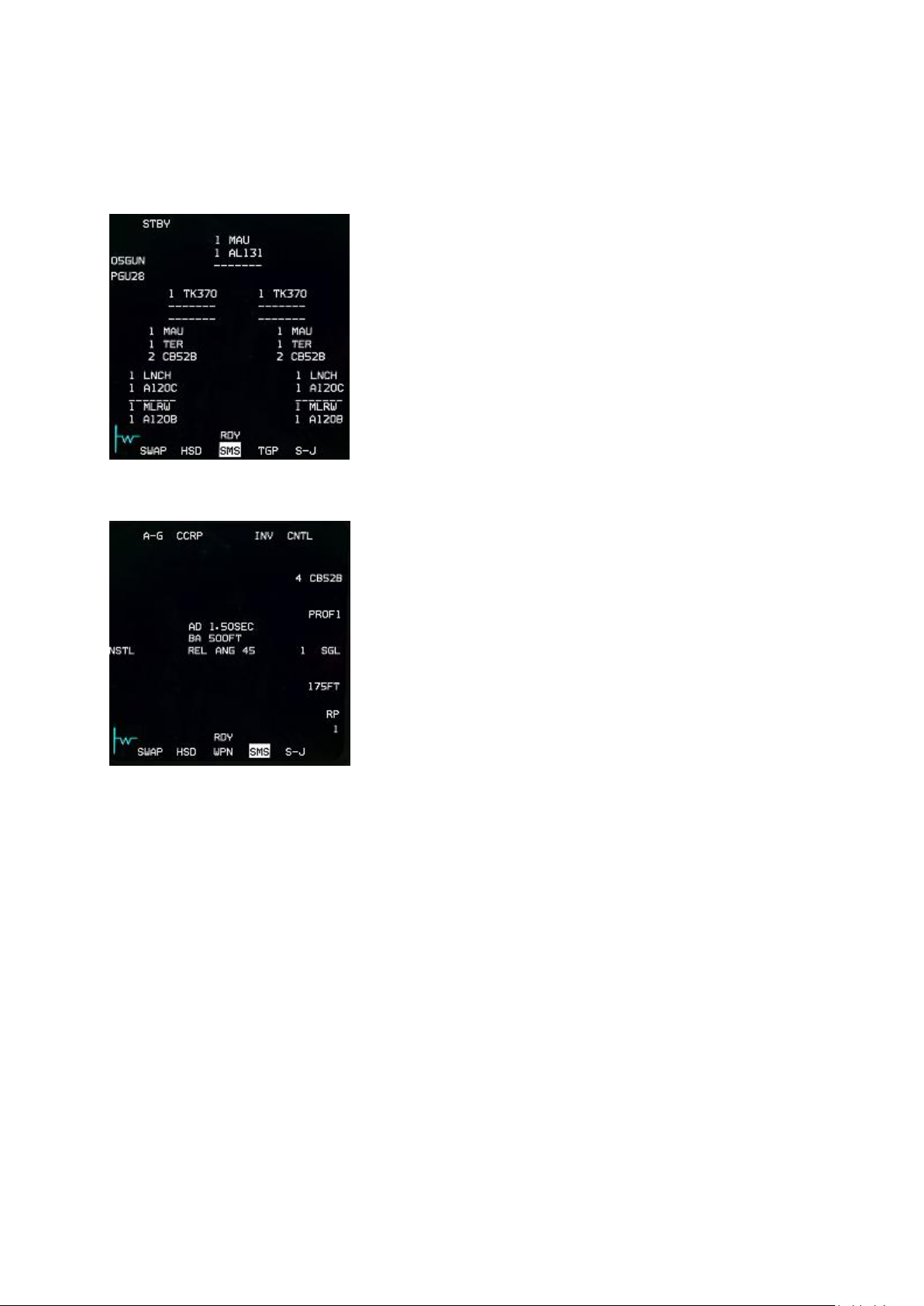
T.O. BMS1F-16CM-1 BMS 4.34 Change 2.00
BMS 4.34 Dash 1
© Red Dog 2012-2019 Page: 87
1.4.5. SMS page
The SMS page will be different depending on the Master Mode you are in when it is selected:
1.4.5.1 SMS in NAV mode:
The SMS page will display the system inventory, graphically
depicting the loading of your aircraft with all its stores and pylons.
In the real jet this page is fully programmable but in BMS it
always reflects the pre-loaded stores perfectly.
Please note the usual DCLT option on OSB #11 is replaced by
the S-J page access. Pressing the S-J button enters the Stores
Jettison Master Mode and associated MFD subpage, which is
documented later in this manual.
1.4.5.2 SMS in A-G mode:
When SMS is selected and the Master Mode is A-G the SMS
page displays only information relevant to A-G weapons.
The information displayed in the centre is the current weapon
arming setting from the CNTL page.
• OSB #1 displays the current Master Mode and if
depressed selects the A-G strafe gun mode and its associated
SMS subpage.
• OSB #2 is used to toggle delivery mode CCIP – CCRP –
DTOS – LADD & MAN. Each has an associated subpage.
• OSB #4 is labelled INV and displays the Inventory page,
should it be needed outside of NAV mode.
• OSB #5 (CNTL) is the Control page for the currently
selected weapon (see below).
• OSB #6 shows current active weapon, type and quantity
aboard. When depressed the next different A-G weapon type is selected in sequence. Please
note the MSL STEP button on the sidestick does not perform the same function - it switches to
the next pylon loaded with the same type of A-G ordinance. This allows the pilots to preprogram two missiles differently if needed such as in the case of HARM missiles for POS
EOM shots.
• OSB #7 is labelled as the currently loaded profile for freefall A-G stores. The SMS is able to
save two different weapon profiles PROF1 and PROF2. By default CNTL settings refer to
PROF1 but if you depress OSB #7 and select PROF2 all settings made will be recorded for
the second weapon delivery profile. This allows the pilot to save two weapon settings and
toggle easily from one to another depending on the situation.
• OSB #8 is SinGLe or PAIR release for A-G stores. Pressing the button will toggle between
SGL and PAIR.
• OSB #9 is the set spacing for A-G ripple stores. When pressed the SMS enters a specific
page where a new spacing value in feet can be input. This is relevant when dropping more
than one weapon to correctly space out the weapon hits.
• OSB #10 is the ripple value for A-G stores. This is the number of weapons that will be
released each time you pickle. When depressed the SMS enters a specific page where the
new value can be input.
• OSB #18 is the fusing option for A-G stores. When depressed it toggles between NOSE, TAIL
and NSTL (both nose and tail) fuses.
Page 88
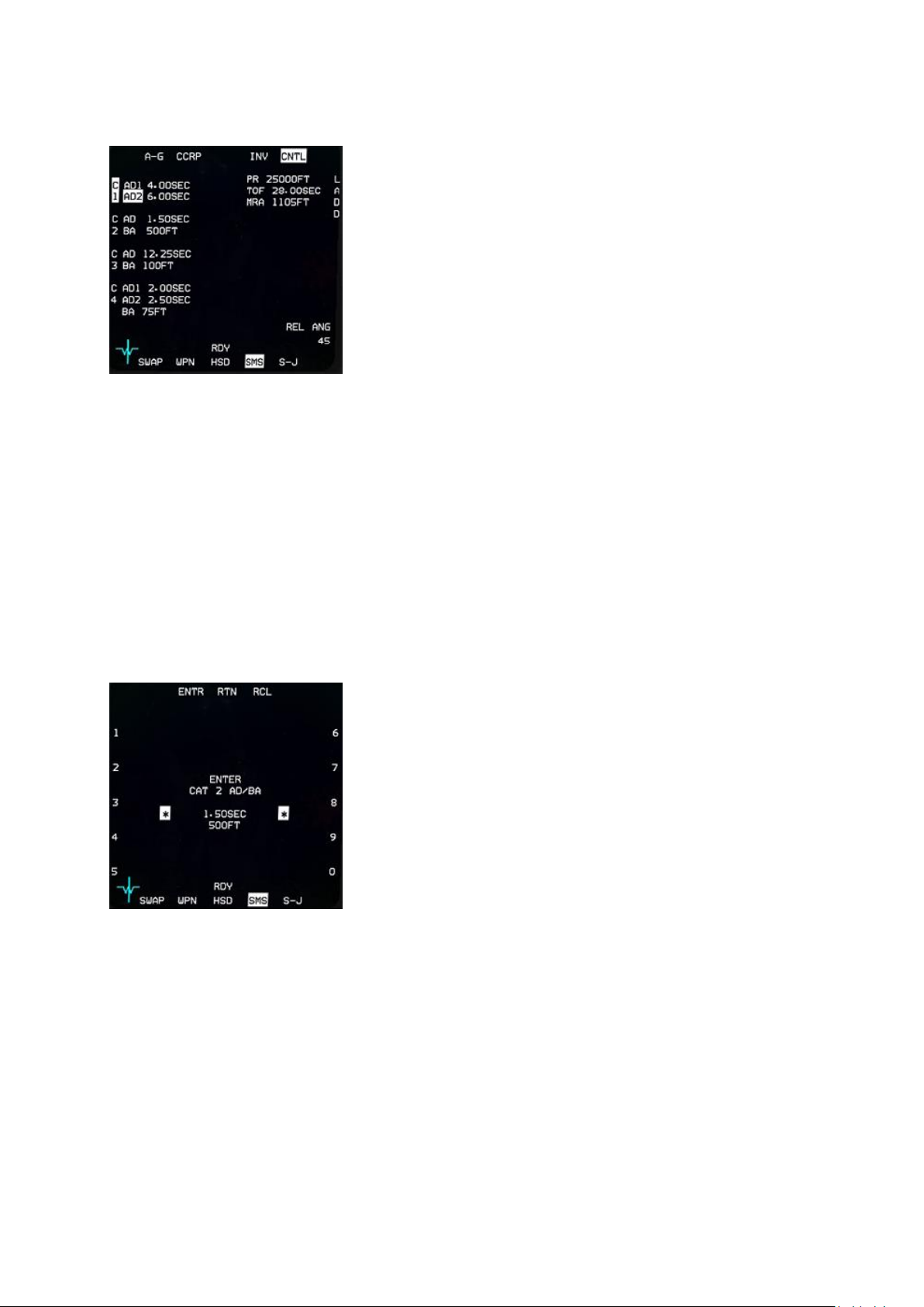
T.O. BMS1F-16CM-1 BMS 4.34 Change 2.00
BMS 4.34 Dash 1
© Red Dog 2012-2019 Page: 88
SMS A-G Control page
While the CNTL page is displayed OSB #5 remains highlighted.
The top & bottom OSB lines are the same as the main SMS page.
What is of interest is the left line of OSB buttons (#16 to 20) and
OSB #6 to the right, which give access to 5 different weapon
settings: C1, C2, C3, C4 and LADD.
C1 (OSB #20) is relevant to General Purpose weapons or Laser
guided weapons and provides two different arming delays. One for
the NOSE fuse and the second for the TAIL fuse. Depress OSB
#20 to enter a subpage where both timings can be set.
C2 is relevant to Cluster Bomb Units or any weapon requiring a
Burst Altitude (BA). Pressing OSB #19 will enter a SMS subpage where both the arming delay and the
burst altitude can be set.
C3 is an additional setting for CBUs, with the same Arming Delay (AD) and Burst Altitude (BA) options
as C2.
C4 is specifically for double fused CBUs. On this page AD1, AD2 and BA can be set.
LADD stands for Low Altitude Drogue Delivery and although OSB #6 has a profile for it, it is currently
not implemented in BMS.
OSB #10 is the setting for the planned release angle. This value is required by the computer to
calculate the correct symbology for DTOS deliveries.
Most of the time C1 and C2 are used if you deploy GP/LGBs or CBUs.
The way settings are input is always the same:
Depress the relevant OSB (C1 to C4) and the subpage is
displayed with the settings in the middle of the page.
The current active setting is displayed between the scratchpad
asterisks and numbers 0 to 9 are displayed next to the left and
right rows of OSB buttons.
To enter a new value simply use the OSB next to the number you
want until the correct value is set, then use OSB #2 ENTR to
confirm the value and the next line of setting will be selected for
change. If there is no next line available the ENTR button will exit
the CNTL page and return to the SMS base page.
OSB #3 (RTN) returns to the previous value or page.
OSB #4 (RCL) deletes the last alphanumerical value input.
Page 89
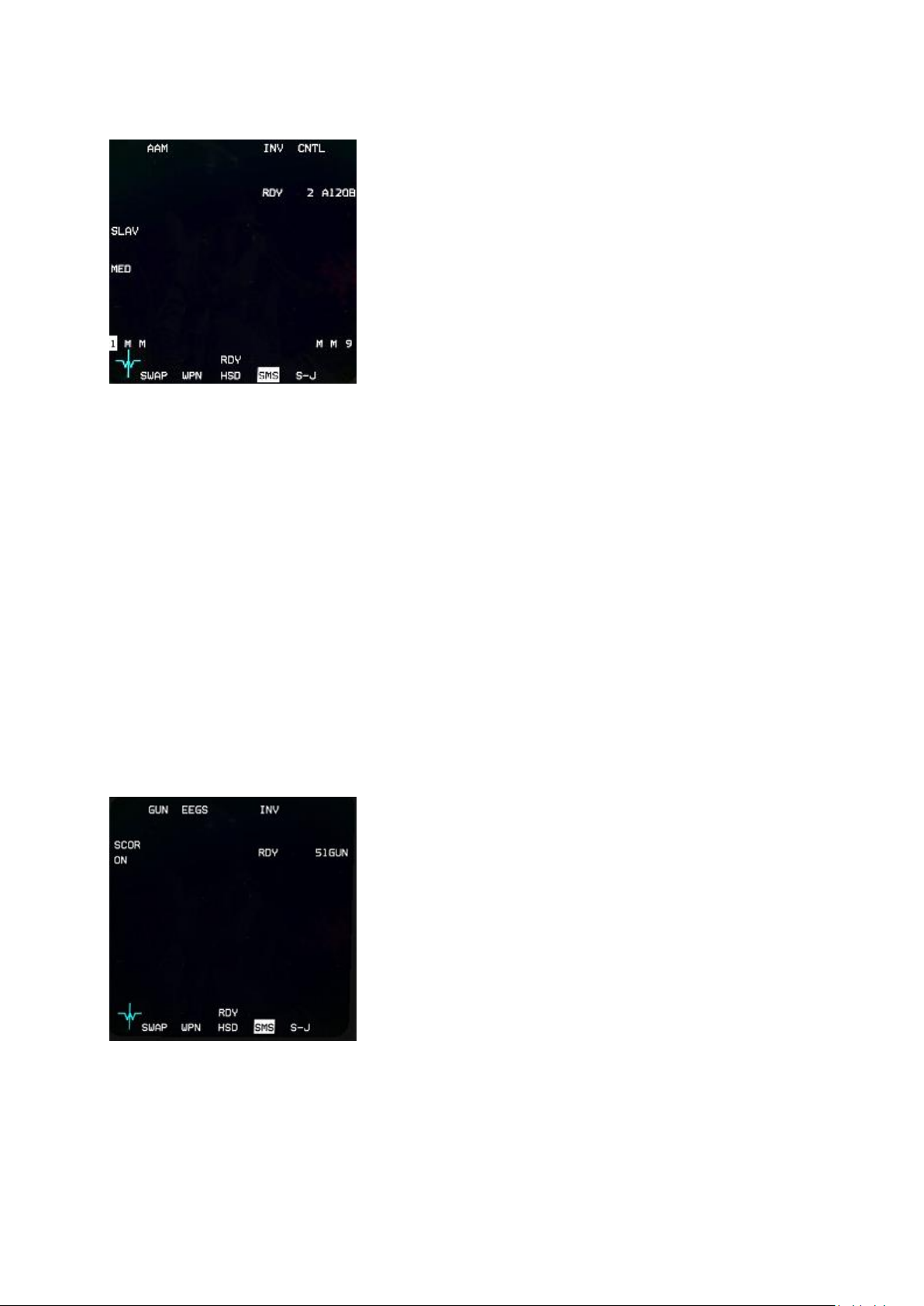
T.O. BMS1F-16CM-1 BMS 4.34 Change 2.00
BMS 4.34 Dash 1
© Red Dog 2012-2019 Page: 89
1.4.5.3 SMS in A-A mode:
The AAM SMS base page has the same structure as the A-G
SMS page.
• OSB #1 displays the current Master Mode and if
pressed selects the A-A gun SMS subpage.
• OSB #3 is active when infrared weapons are carried and
is displayed SPOT. It changes the AIM seeker from SPOT to
SCAN.
• OSB #4 is labelled INV and displays the Inventory page,
should it be needed.
• OSB #5 (CNTL) is the Control page for the currently
selected weapon.
• OSB #6 shows the current active weapon, type and
quantity aboard. When depressed the next different A-A weapon loaded hardpoint is selected
in sequence. Please note: the MSL STEP button on the sidestick performs the same function
if held for more than half a second. If held for less than half a second it switches to the next
hardpoint carrying the same type of A-A missile. You can see the hardpoint configuration in
the picture above. Station 1 is currently selected and carrying an AIM-120B. Station 9 carries
the same type of weapon and stations 2, 3, 7 and 8 carry medium range missiles (M)
• OSB #8 (WARM/COOL) is displayed when infrared weapons are carried and shows the status
of the IR seeker on the missile. Pressing WARM allows you to cool the seeker. This is done
automatically in DGFT mode with MASTER ARM in ARM or SIM.
• The bottom row has the usual functions including S-J available.
• OSB #18 is dependent on missile type.
For radar missiles it sets the PRF range and toggles between unknown, large, medium and
small targets. Large is used for bombers, medium is used for fighters and small is used to
intercept missiles (not implemented).
For IR missiles it toggles from BP (Bypass) to TD (Threshold Detection). When set to TD the
missile will automatically uncage. When set to BP the missile needs to be uncaged manually.
• OSB #19 toggles SLAVE or BORE.
Radar missiles can be set to SLAVE or BORE. When set to SLAVE the missile is slaved to the
FCR and when set to BORE the missile is pointed six degrees below the gun cross and will
fire without command guidance. It will switch on its own radar and go autonomous right after
launch. That’s a MADDOG shot as it will go after the first thing it ‘sees’.
Depressing OSB #1 selects the A-A gun and the A-A gun SMS subpage is displayed:
OSB #1 displays GUN
OSB #2 sets the A-A Gun mode (EEGS etc.) through a subpage
OSB #4 displays the Inventory page
OSB #6 displays the amount of ammo remaining for the gun. 51
means 510 rounds. Each burst is 10 rounds by default.
The bottom row has the usual functions.
OSB #20 is labelled SCOR and toggles ON or OFF.
When ON it allows the BATR circle to be displayed in the HUD
when the gun is being fired as well as the FEDS markers.
The BATR (Bullets at Target Range) circle for EEGS is a 6-mil circle displayed after the trigger is
squeezed and the bullets have travelled to the target. It disappears after the last bullet passes through
the target range (it actually disappears 1 second after the trigger is released; which is good enough for
the time being). The BATR is nothing more than a record of where the gun cross has been pointed
(corrected for gravity drop).
Page 90
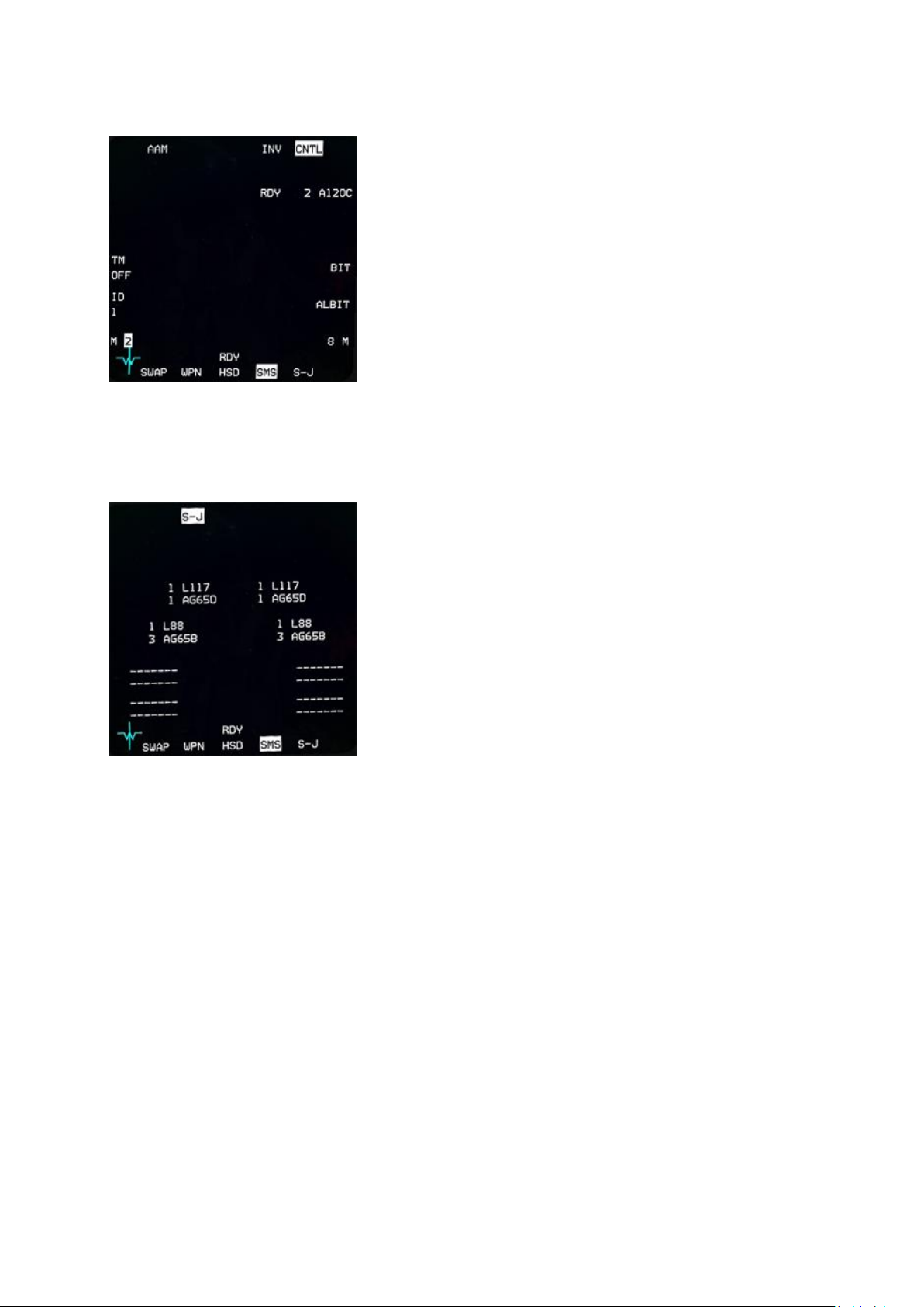
T.O. BMS1F-16CM-1 BMS 4.34 Change 2.00
BMS 4.34 Dash 1
© Red Dog 2012-2019 Page: 90
Depressing OSB #5 enters the CNTL page:
When the A-A CNTL page is selected OSB #5 CNTL is
highlighted.
There is not much to set here, except perhaps the MSL ID which
should match your flight # ID. It is good practice to set your MSL
ID to #2 for instance if you fly as wingman in a two ship.
This would serve the FCR datalink should it be implemented one
day. For the moment it is not implemented in BMS.
1.4.5.4 Selective Jettison (S-J) page:
The S-J page is accessible in NAV, A-G and A-A modes from
the SMS base page OSB #11.
Selective Jettison is a Master Mode.
This allows the pilot to jettison weapons and racks unarmed or
unguided from selected aircraft stations. Only jettisonable stores
will be displayed for selection. The pilot presses the OSB
adjacent to the station displayed on the S-J page. The selected
station’s bottom-most store is highlighted on the S-J page,
indicating that it is selected. If a jettisonable rack is also loaded it
may also be selected with a second press of the OSB. A third
press will then deselect all stores on that station. The pilot can
preselect a selective jettison configuration while in S-J Master
Mode, which will be remembered during Master Mode
transitions. The stores are jettisoned using the pickle button
when the MASTER ARM switch is in ARM. After the stores are
released the highlighted stations are removed from the S-J page and the associated weapon quantity
reads zero. The S-J mode also bypasses any other weapons settings.
Page 91
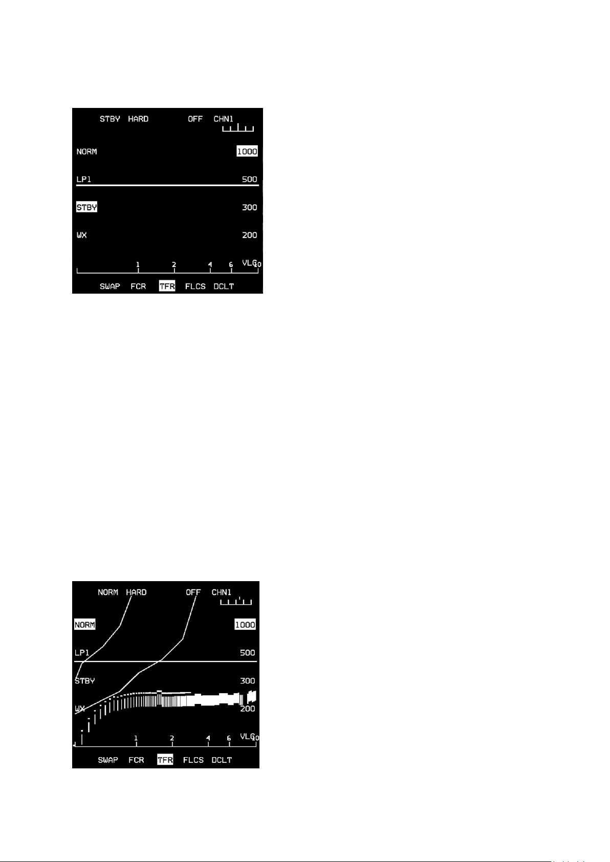
T.O. BMS1F-16CM-1 BMS 4.34 Change 2.00
BMS 4.34 Dash 1
© Red Dog 2012-2019 Page: 91
1.4.6. TFR page
The Terrain Following Radar was completely updated in
4.33 and is now fully operational.
TFR is only available on F-16s carrying an AN/AAQ-13
LANTIRN navigation pod (on the left chin station).
The TFR is a short range (36000ft) forward and down
radar that allows you to follow the terrain at very low
altitude with automatic fly up protection.
The TFR page can be reached from the menu page by
depressing OSB #17. As with all pods / systems the TFR
needs a certain amount of time to become operational.
This time starts when the TFR is placed out of OFF to
STBY. The TFR is ready when the NOT TIMED OUT
message disappears. Obviously the chin hardpoints must
be powered and the radar altimeter must be operational.
The TFR has 7 modes of operation: OFF – BIT – STBY –
NORM – LPI – WX – VLC
OFF: the TFR is not powered.
BIT: (N/I) is accessed from the MFD TEST page.
STBY: the pod is in standby mode and not operative (see picture above).
NORM: is the normal mode of operation and accessed with OSB #20. It has 3 submodes:
MAN TF: the pilot receives FPM cueing (MAN TF box) in the HUD to maintain a selected altitude
above ground level. He hand flies the jet but the TFR offers automatic fly-up protection if the MANUAL
TF FLYUP switch is in ENABLE. The ADV light on the MISC panel is unlit.
AUTO TF: the flight control computer uses the vertical acceleration commands generated in the
LANTIRN pod to maneuver the aircraft to maintain the selected SCP (Set Clearance Plane) altitude. In
AUTO TF the ADV light on the MISC panel has the top indicator (ACTIVE) lit and a horizontal line is
shown near the FPM on the HUD. The pilot can override the TFR (just like the autopilot) by depressing
the paddle switch on the stick. While the paddle is depressed the STBY (bottom part of the ADV) light
on the MISC panel is illuminated.
Blended TF: the autopilot is engaged to hold a specific barometric altitude (or attitude). If the
LANTIRN pod detects the aircraft violating the selected minimum AGL the system will automatically
maneuver the aircraft to maintain the minimum AGL until the terrain has dropped away. A/P PITCH
switch is in ALT or ATT HOLD. STBY ADV light is on. Horizontal line is visible.
LPI: is Low Probability of Intercept. It allows minimal TFR use with the RF switch placed in the QUIET
position. It is activated by pressing OSB #19 or automatically upon placing the RF switch in QUIET.
Please note: placing the RF switch in SILENT places the TFR in STBY.
WX: is used in bad weather (rain) to minimize uncommanded fly-ups due to conflicting radar returns in
rain or fog. It is activated with either the MFD TFR page OSB#17 or the ICP WX button.
VLC: is Very Low Clearance (100ft SCP) and accessed from OSB #10. This mode is to be used only
on relatively flat terrain or over water.
The TFR has 3 Ride options: HARD - SOFT - SMTH
(smooth) available on the OSB#2 rotary.
Activate the TFR by placing it in NORM and select the
desired SCP. Both options highlight on the TFR page. In
this example we set 1000 feet. The A-LOW in the DED
should be set to SCP-10% (in this case 900 feet). The TFR
E-scope display will start displaying a visual representation
of the terrain ahead. The pilot can then decide if he wants
MAN TF or AUTO TF. AUTO TF is engaged by depressing
the ADV indicator/pushbutton on the MISC panel.
Automatic fly-up protection is provided in AUTO TF; in
MAN TF you must have the MANUAL TF FLYUP switch in
ENABLE.
Refer to Avionic Checklists for TFR checks (in your Docs
folder). More detailed information on the TFR is available
in the TFR chapter of the TO-BMS1F-16CM-34-1-1.
Page 92
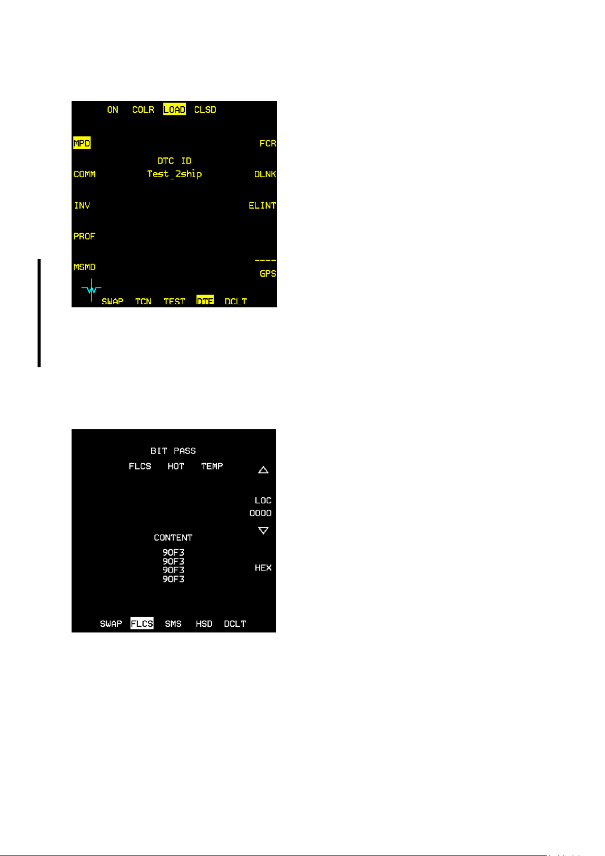
T.O. BMS1F-16CM-1 BMS 4.34 Change 2.00
BMS 4.34 Dash 1
© Red Dog 2012-2019 Page: 92
1.4.7. DTE page
The DTE page is accessed from the menu page by
depressing OSB #8.
It is used to load the Data Cartridge prepared during
mission planning in the UI into the aircraft computer.
Loading is done (usually at ramp start right after or just
before switching the CNI to UFC) by depressing OSB
#3.
Each displayed system (MPD, COMM etc) is
highlighted in sequence during loading and the DTC
changes should be visible in the DED (presets for VHF
and UHF amongst others).
The DTE page has been updated for 4.34. Each
system is now loaded as it is highlighted in a counterclockwise sequence from the LOAD button. Some
systems take longer than others to load, just as they
do in the real jet.
COLR is used to manually load any colour profile you have set up using Avionics Configurator and
saved to your [callsign].ini file, for example to turn yellow MFDs back to white, or change any other
aspect of the symbology to your preference, just as you can do in the real aircraft. (See the Avionics
configurator chapter in the BMS Technical Manual)
1.4.8. FLCS page
The FLCS page is accessed from the menu page by
depressing OSB #10.
The FLCS page provides an overview of anything
related to the FLCS. The page provides a backup
display for the FLCS faults by showing up to 5 FLCS
faults or warnings. As with the PFL the warnings are
displayed within ><. When more than 5 faults are
present they can be reviewed by pressing OSB #20
labelled MORE.
This can be very helpful in case of UFC failure that will
blank both the DED and the PFL and will prevent the
pilot from seeing any faults. On the FLCS page at least
the FLCS related faults can be reviewed.
The FLCS page content can be reset by switching to
DBU (digital backup) mode and back for digital FLCS
equipped jets. The FLCS RESET switch will also clear
the FLCS page.
The FLCS page will also report the status of the FLCS BIT and status of the DBU if the jet has a digital
FLCS.
When the FLCS suffers from a BUS FAIL the FLCS page will show OFF and cannot be used to review
FLCS faults.
If the jet is equipped with digital FLCS the maintenance functions and addresses are displayed in the
middle and bottom part of the MFD when the jet is on the ground. Once in flight the maintenance
functions are deleted and the FLCS page is usually blank unless FLCS malfunctions are present.
Page 93
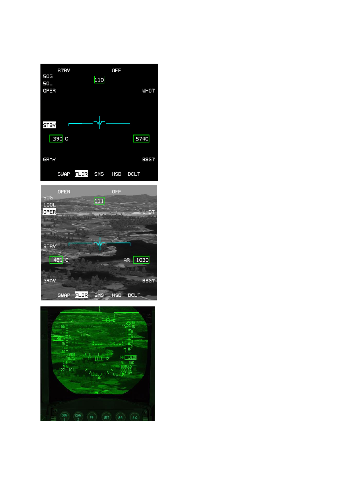
T.O. BMS1F-16CM-1 BMS 4.34 Change 2.00
BMS 4.34 Dash 1
© Red Dog 2012-2019 Page: 93
1.4.9. Forward Looking Infrared (FLIR) page
The FLIR page is only available on F-16s carrying an
AN/AAQ-13 LANTIRN navigation pod (on the left chin
station). The FLIR is a forward looking infrared
camera used for low level night navigation. The FLIR
is housed in the navigation pod of the LANTIRN
system mounted alongside the TFR system.
Obviously chin hardpoints must be powered up for the
FLIR to be operational.
The FLIR needs between 8 and 15 minutes to cool
down before use, so start the process as soon as
possible during ramp start for missions requiring FLIR.
The FLIR will be ready to operate as soon as the NOT
TIMED OUT message disappears from the MFD.
OSB #18 places the FLIR in standby. OSB #20 places
the FLIR in operational mode (OPER). Once
operational the FLIR page will display the infrared
view in front of the pod. The image can be repeated
on the HUD by rotating the BRT ICP wheel upwards.
The FLIR level can be changed with the ICP up and
down FLIR arrows. The current gain and level values
are displayed on the top left corner of the FLIR MFD.
OSB #10 is the boresight option. On the ground the
FLIR camera is boresighted on top of the HUD. It may
induce parallax errors. The boresight is used to better
match the image in the HUD with the image from the
FLIR camera at a certain range. Depress OSB#10 and
the BSGT mnemonic highlights. The HUD FLIR image
can then be slewed with the cursors. Do not boresight
on close objects. It is advised to boresight in flight on
large objects such as the edge of a mountain or a road
for instance. Once both images are superimposed
correctly depress OSB#10 again and the BSGT
mnemonic will return to its initial state.
Once the FLIR image is displayed on the HUD the
MFD page does not need to be active, though it is
advisable to have it on one of the DA buttons for easy
access to boresighting.
LOOK-INTO-TURN (LIT) and SNAPLOOK capabilities
are available on the HUD.
LIT: when the bank angle is above 5° holding DMS UP
will shift the FLIR view slightly into the turn to provide
lead obstacle clearance. The FLIR image reverts to
forward looking when DMS UP is released.
SNAPLOOK: The view can be shifted further in flight
by holding DMS UP and moving the cursors in any
direction, even in a turn. The view will revert to forward
looking when DMS UP is released.
When LIT or SNAPLOOK are active the FPM is
dashed.
More information can be found in Avionic Checklists
and the TO-BMS1F-16CM-34-1-1 LANTIRN chapter (in your Docs folder).
Page 94
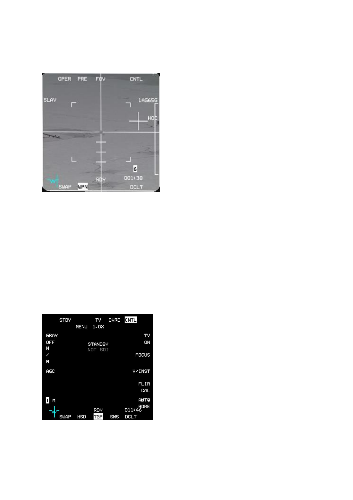
T.O. BMS1F-16CM-1 BMS 4.34 Change 2.00
BMS 4.34 Dash 1
© Red Dog 2012-2019 Page: 94
1.4.10. WPN page
The WPN page is accessed from the menu page by depressing OSB #18.
It gives the pilot access to onboard weapons sensors.
Some weapons such as AGM-65 Mavericks and the
AGM-88 HARM have onboard sensors that may be
used to acquire and lock targets. Since the sensor is
onboard the missile it should be obvious that once the
missile is away the MFD can no longer display the
sensor image.
HARMs
POS EOM is displayed on the WPN page when the
HARM is selected and ready.
See weapon specific documentation for HARM
deployment.
Mavericks
The IR image from the missile head is displayed in the
WPN MFD page once the IR head has been uncaged
(and any dome covers removed). See weapon specific
documentation for Maverick deployment.
• OSB #1: reports status
• OSB #2: toggles PRE-VIS-BORE modes
• OSB #3: sets the Field of View
• OSB #5: accesses the Control page
• OSB #6: displays the type of weapon currently selected
• OSB #7: toggle polarity
• Bottom row has the usual DCLT, Direct Access and SWAP buttons
• OSB #20: selects the SLAVE options
For further information on specific weapon employment please refer to the relevant chapter in the
TO-BMS1F-16CM-34-1-1.
1.4.11. TGP page
The TGP page is accessed from the MENU page by
depressing OSB #19.
The TGP is active when either a LANTIRN or SNIPER
pod is carried on the chin pylon and powered up.
This is done on the SNSR PWR panel with the RIGHT
HDPT switch. The TGP needs to cool down after
powering up and the TGP page will display NOT TIMED
OUT until the pod is ready.
See the TO-BMS1F-16CM-34-1-1 for more information
about the LANTIRN and SNIPER TGPs.
Page 95
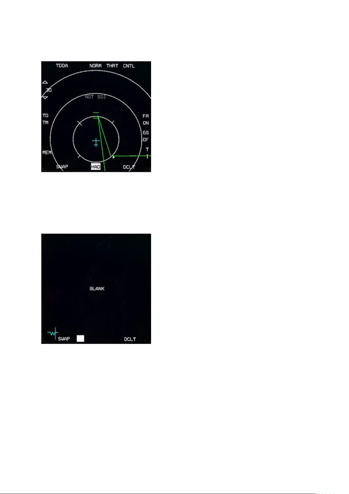
T.O. BMS1F-16CM-1 BMS 4.34 Change 2.00
BMS 4.34 Dash 1
© Red Dog 2012-2019 Page: 95
1.4.12. HAD page
The HARM Attack Display is selected from the MENU
page by pressing OSB #2 (if you have a HTS pod fitted
and the LEFT HDPT powered up).
The HAD may be selected in any Master Mode and
shares many common display features with the HSD.
HAD cursor movement and expanded FOV (OSB #3 or
pinky switch) options are similar to the HSD as well.
The pilot may select the HAD range (with HAD as SOI) by
slewing the cursors up and down the display to bump
range or by pressing OSBs #19 and #20.
The HAD is not the only way to deploy AGM-88s. POS
and HAS modes are accessible through the WPN MFD
page with HARMs loaded (as long as HAD is not SOI).
The HARM WEZ footprint is based on Rmax of the AGM88 and will increase or decrease in size according to your
speed and altitude. If the HARM WEZ is greater than the
selected display range the lines will be dashed.
Detected emitters are coloured as follows:
Green = emitter not active
Yellow = emitter active
Red = emitter tracking
Flashing Red = emitter launching
1.4.13. BLANK page
It is possible to turn off one MFD by selecting the BLANK
page with OSB #1 on the MENU page.
Although you may think that it is completely pointless it
can be helpful when you need only one MFD page active
from the Direct Access row for a specific Master Mode.
For example if you only want FCR to be displayed on the
left MFD in A-A Master Mode you would simply program:
FCR - BLANK - BLANK in the DTC.
1.4.14. RCCE page
The RCCE page (OSB #4 from the menu page) is intended for interfacing with reconnaissance pods,
but is not implemented in BMS. Even the low altitude camera in the weapon inventory does not use it.
Page 96
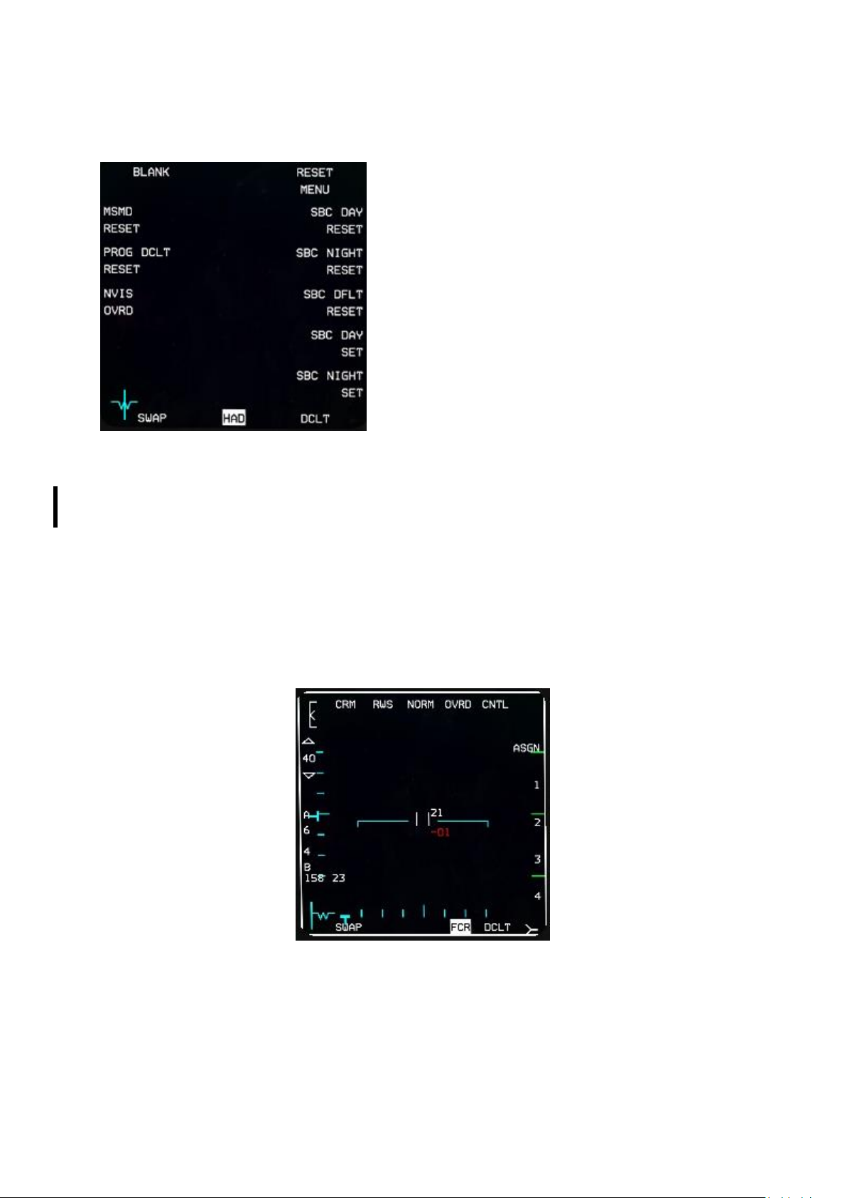
T.O. BMS1F-16CM-1 BMS 4.34 Change 2.00
BMS 4.34 Dash 1
© Red Dog 2012-2019 Page: 96
1.4.15. RESET MENU page
The RESET menu is accessed via OSB #5 of the MENU
page but has no purpose in BMS. None of its functionality
is implemented.
1.4.16. FCR page
The Fire Control Radar page is accessed from the menu page by depressing OSB #20.
The radar is now fully documented in the TO-BMS1F-16CM-34-1-1 AN/APG-68(V)5 FIRE CONTROL
RADAR chapter. Here is a short introduction which hopefully will meet your immediate needs.
Obviously this page displays a visual representation of what the radar detects. It can be set to A-A
radar and its submodes, or A-G radar depending on Master Mode.
1.4.16.1 FCR in A-A modes
The FCR is switched on by the FCR switch on the SNSR panel and once powered enters a BIT (Built
In Test) that may last a few minutes. If the FCR is switched off in flight for longer than 4 seconds the
BIT will be reinitialised.
Once the BIT is complete the FCR becomes available and usually defaults to A-A CRM (Combined
Radar Modes).
OSB #1 states the current mode the FCR is in and if depressed displays a page where all other
modes can be chosen from the side MFD buttons: CRM and ACM (Air Combat Maneuvering) on the
left and on the right GM (Ground Mapping), GMT (Ground Moving Target), SEA (Anti-Ship) and STBY
(Standby). Depressing any of the corresponding OSBs will enter that mode. Please note: BCN
(Beacon) mode is not implemented.
Page 97
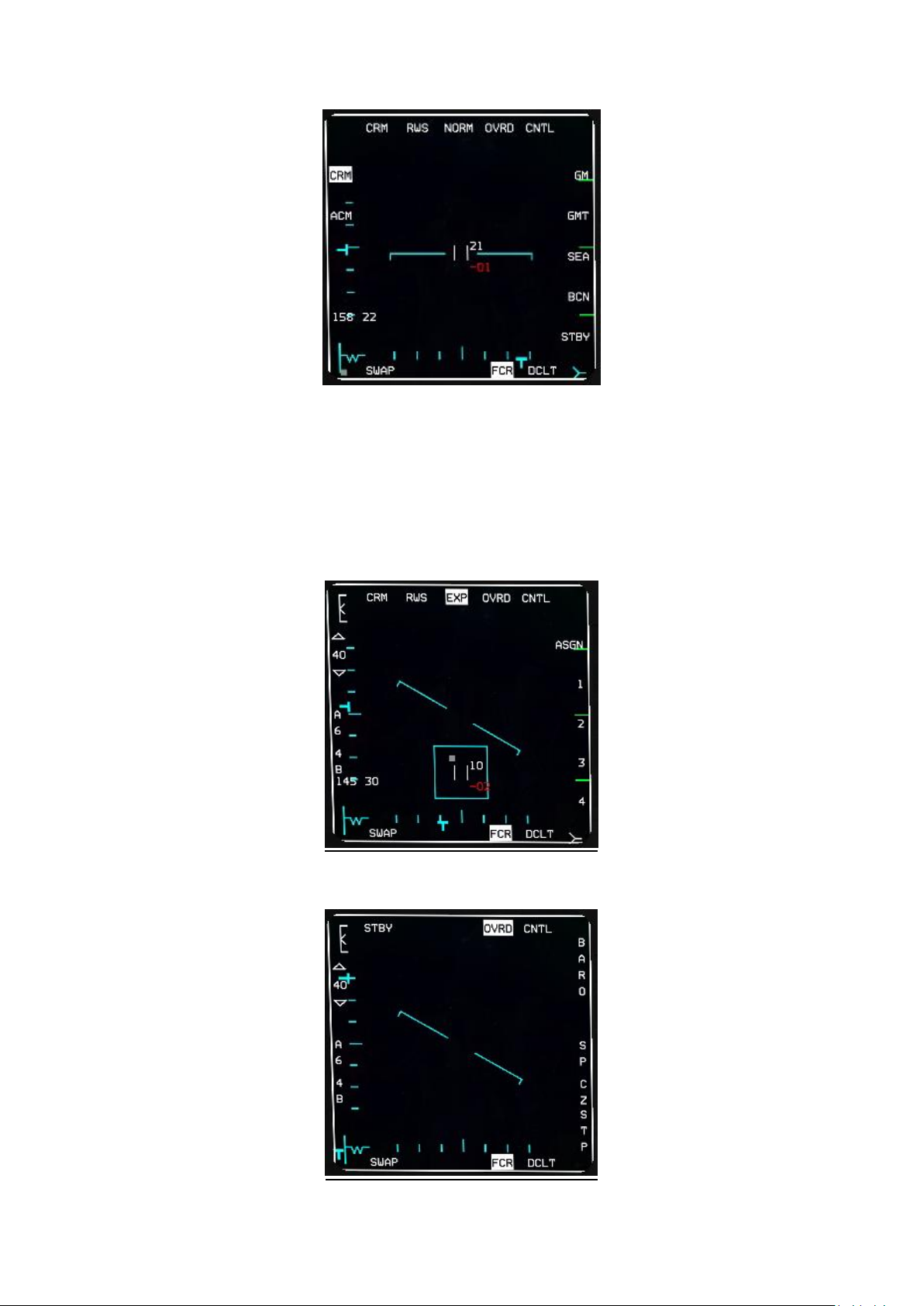
T.O. BMS1F-16CM-1 BMS 4.34 Change 2.00
BMS 4.34 Dash 1
© Red Dog 2012-2019 Page: 97
OSB#2 selects the corresponding submode.
If the FCR is in CRM the submodes are RWS (Range While Search), ULS (=LRS Long Range Scan),
VSR (=VS Velocity Search), TWS (Track While Scan).
If the FCR is in ACM the submodes are 20 (HUD), Slew, Bore, 60 (Vertical).
OSB #3 is FOV and is not available in all modes. It is displayed only when available and will toggle
between NORM and EXP. This can also be done with the pinky switch (S3) on your stick. When
toggled to EXP the area around the cursor is expanded and illustrated by the blue square drawn on
the MFD. The EXP label also flashes.
OSB #4 places the FCR in standby mode. All symbology is deleted from the MFD and OVRD is
highlighted. A further press on OSB #4 reverts back to operating mode.
Page 98
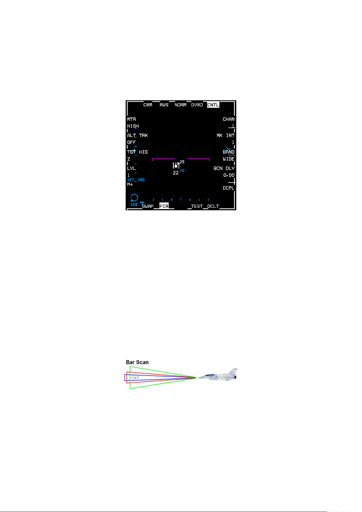
T.O. BMS1F-16CM-1 BMS 4.34 Change 2.00
BMS 4.34 Dash 1
© Red Dog 2012-2019 Page: 98
OSB #5 enters the FCR control page. The left and right rows of OSBs can set different options but
most of those are not implemented yet and are eye candy only. The exception is TGT HIS which sets
the number of toned down contacts you see after the main contact and Advanced IFF (AIFF)
CPL/DCPL adjacent to OSB 10. Selection couples the AIFF Interrogator FOV to the FCR FOV in the
AIFF scan mode. The control page is the same in both A-A and A-G FCR modes and is detailed in the
A-G FCR section further down this chapter.
OSB #6 is the IDM mode. It defaults to ASGN (Assign) but can be toggled to CONT (Continuous) or
DMD (Demand).
OSB #7, #8, #9 & #10 are labelled 1, 2, 3 and 4 and correspond to your flight members. These are
used to select a specific flight member to send IDM data to. Please refer to the IMPROVED DATA
MODEM chapter of the TO-BMS1F-16CM-34-1-1 for further information on A-A IDM.
The bottom row has the usual Direct Access buttons with DCLT on OSB #11 and SWAP on OSB #15.
OSB #17 is the bar scan and can be toggled from 1 bar to 4 bar.
The FCR scans the horizon by physically moving the antenna. The beam that the antenna normally
emits is not able to scan more than 4.9° in the vertical. So with this set to 1 the radar will scan just the
single 4.9° slice of airspace. Set to 2 the radar will scan 2 bars of airspace, set to four it will scan four
bars. It takes 2.5 seconds to scan one bar and another 0.5 seconds to move the antenna up and start
on the next bar, so a full 4 bar scan will take 12 seconds, whereas a 1 bar scan will take just 2.5
seconds. Obviously decreasing the bar scan will quicken the scan but will reduce the search area.
Regardless of the bar scan setting the radar can always be tilted up or down with the ANTENNA
elevation control on the throttle.
OSB #18 is the azimuth setting and toggles between a cone of 60° (A6), 30° (A3) and 10° (A1).
Blue vertical lines are drawn on the FCR to illustrate the reduced search area and it is displayed
similarly on the HSD. The obvious advantage is that the smaller the search area the quicker the scan
happens. The disadvantage is that it becomes easier to miss a contact that might be outside your
search area. When the azimuth is less than 60° the search area is slewable using the cursors.
Page 99
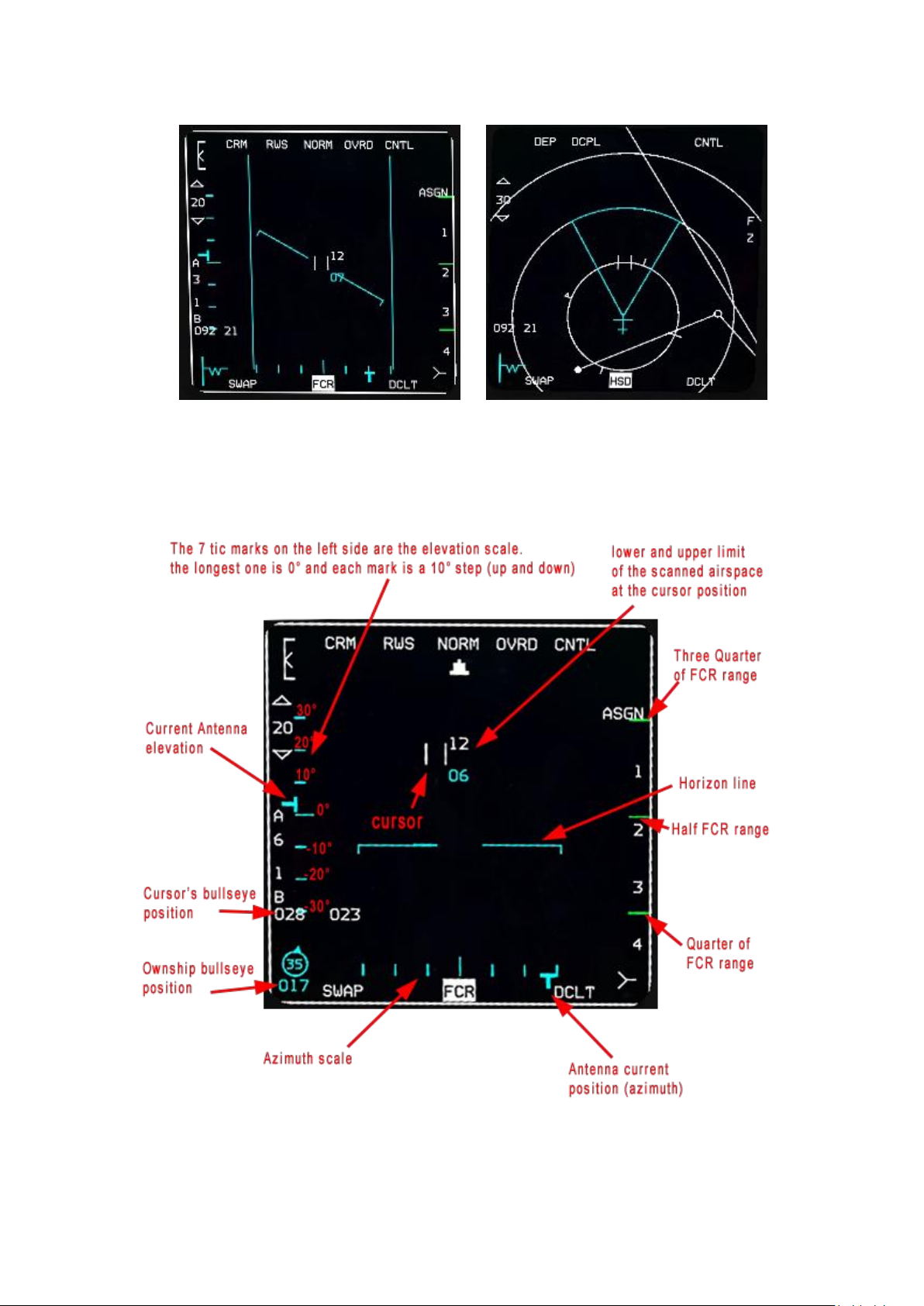
T.O. BMS1F-16CM-1 BMS 4.34 Change 2.00
BMS 4.34 Dash 1
© Red Dog 2012-2019 Page: 99
OSB #19 & 20 are used to set the FCR range when the mode allows it. Depressing OSB#19
decreases range and OSB#20 increases range. Another way to set the range is by cursor bumping (if
the FCR is SOI) whenever the cursors hit the top or bottom edge of the FCR.
Page 100
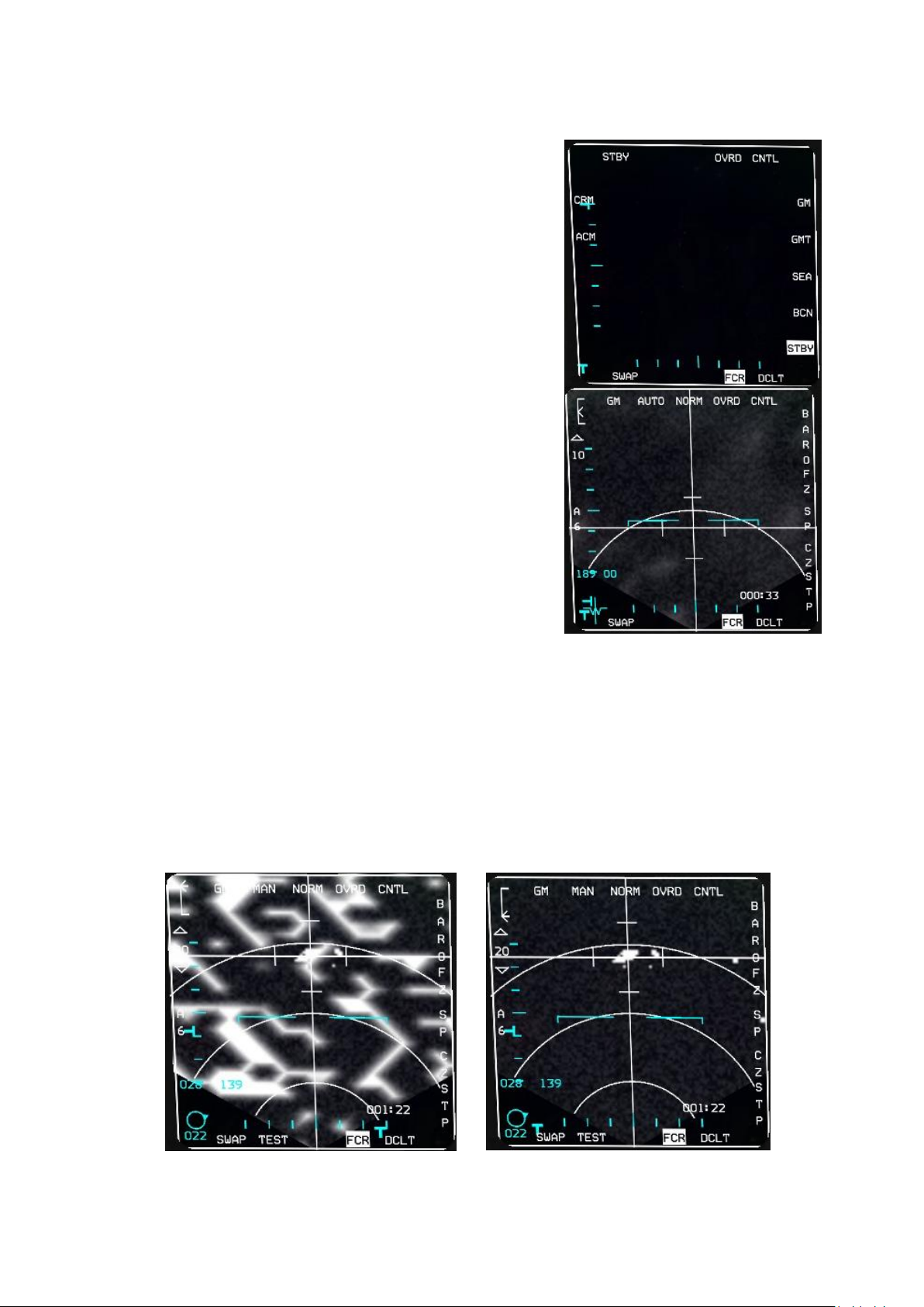
T.O. BMS1F-16CM-1 BMS 4.34 Change 2.00
BMS 4.34 Dash 1
© Red Dog 2012-2019 Page: 100
1.4.16.2 FCR in A-G modes
The FCR will switch automatically to A-G FCR upon entering
A-G Master Mode. If you need to set the FCR to a specific
mode you can use the menu page to select any submodes.
The left side OSBs show the A-A modes and the right side
OSBs access the Ground submodes:
GM: Ground Map
GMT: Ground Moving Target
SEA: for naval targets
BCN: Beacon (not implemented in BMS)
Mechanisation of the A-G FCR is the same for all different A-G
submodes, only sensitivity towards different targets changes.
We will use Ground Map (GM) mode to illustrate the A-G FCR
in this chapter.
Upon first entering GM mode the FCR is scanning ahead and is
pointing at the current active System Point of Interest (SPI). The
time needed to reach the SPI is displayed in the bottom right
corner of the FCR, in this case 33 seconds. This timer may be
specific to other things such as pull up cue and bomb impact for
LGBs. It depends on Master Mode, SOI and SMS.
As with the A-A FCR the cursor’s bullseye position or bearing
and range from the current steerpoint is displayed near OSB#17
according to Bullseye being mode selected or not. In this case
bearing and range is displayed (189 00) as bullseye is not mode
selected. Ownship bullseye position will be displayed in the bottom left corner of the MFD if Bullseye is
mode selected in the DED (LIST 0 8 BULL page). In the picture on the right Bullseye is not mode
selected and thus the MFD displays the aircraft reference symbol (W) and the azimuth steering bar.
In BMS this may vary according to block or export variants, with some aircraft always displaying the
flight director symbol, even with BULLSEYE mode selected.
The A-G radar is able to paint the terrain in different colour depths. Contact returns appear as bright
white dots. The A-G FCR gain can be set with the throttle RNG knob or by using the GAIN rocker
switch (top left corner). The gain changes the intensity of the terrain and is indicated with the Gain
marker displayed in the top left corner of the MFD. The two pictures below illustrate the A-G FCR gain
set to maximum (left picture - notice the gain meter set to the highest point) and set to minimum (right
picture - notice the gain meter all the way to the bottom of the scale). Please note the gain meter is
displayed both in A-A & A-G FCR modes.
 Loading...