

Page 1
IO-28-EN Rev.2
07/05/2015
S
UMMARY
BBIIOOSS PPRROOGGRRAAMMMMAATTIIOON
N
What is necessary for the BIOS programmation ............................................................................................... 1
Pre-Programming phase .................................................................................................................................... 2
Procedure for BIOS programmation .................................................................................................................. 3
Post-Programming phase ................................................................................................................................ 14
Troubleshoot ................................................................................................................................................... 15
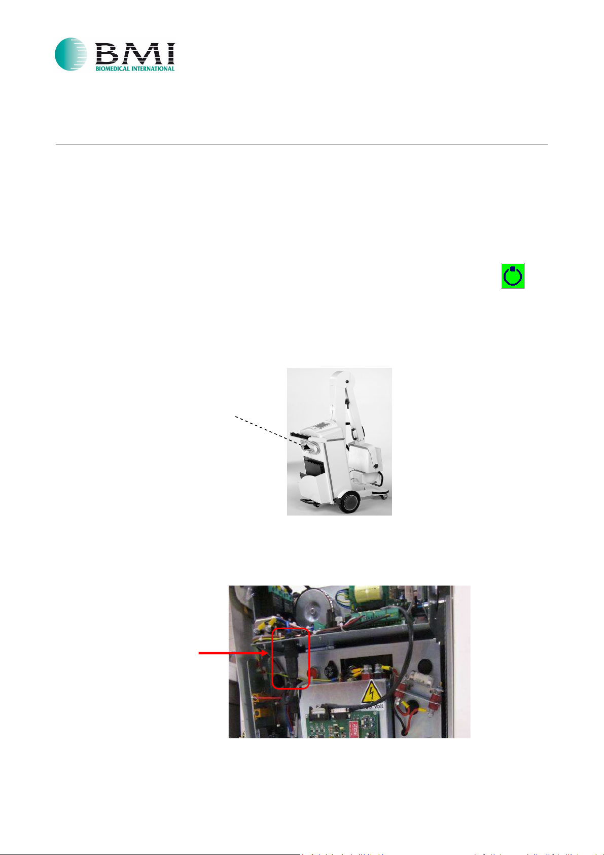
What is necessary for the BIOS programmation
• Allen Key Ø2,5 mm
• Personal Computer (PC) or laptop with an USB/RS232
• HyperTerminal already installed on the PC (if not, ask to the PC administrator for installation)
• SD CARD for programming
ATTENTION: make sure that Display software version is compatible with the software version of Main
Board. Contact the BMI Service Department for this control, providing the unit serial number.
•
Flat cable and jumper
adapter
Page 1 of 17
Page 2
holder
BBIIOOSS PPRROOGGRRAAMMMMAATTIIOON
N
IO-28-EN Rev.2
07/05/2015
Pre-Programming phase
•
Make sure that the equipment is turned off.
•
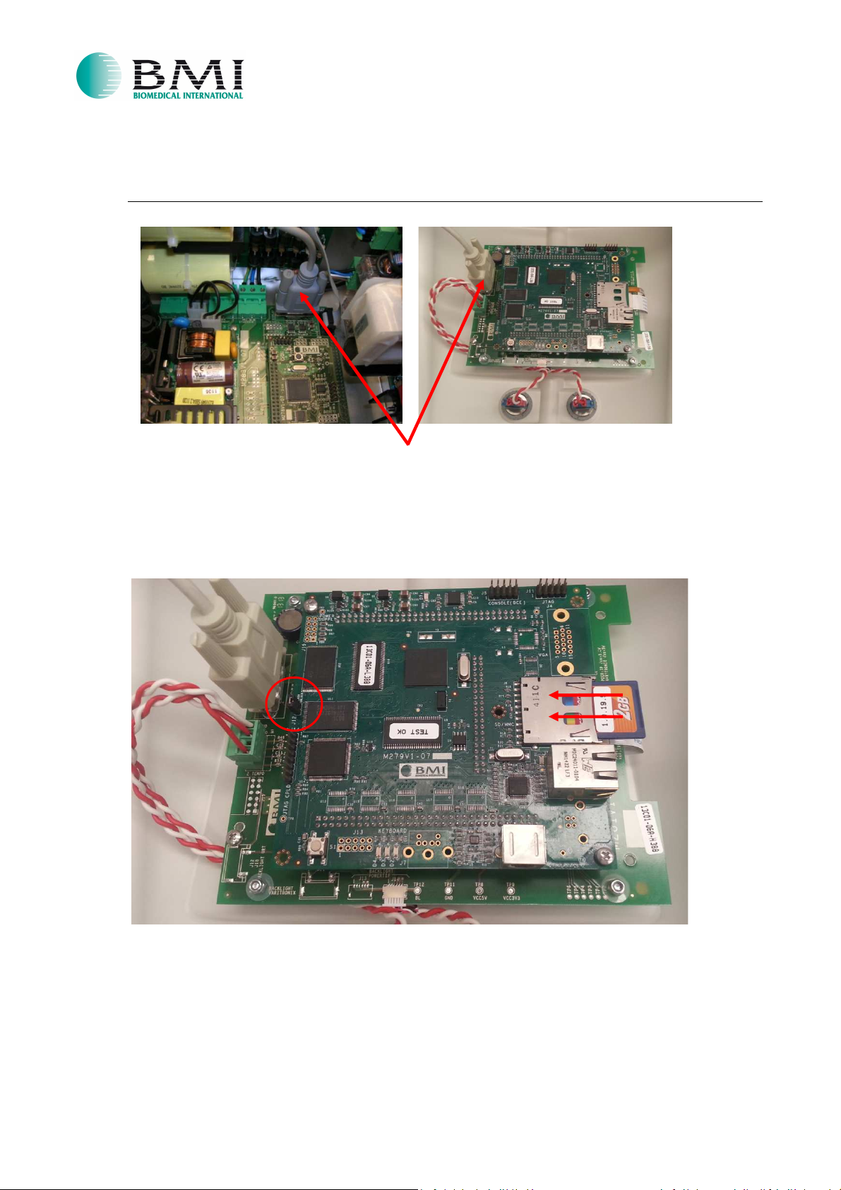
Detach the console from the equipment without disconnect the serial cable. (refer to step 1)
•
In order to prevent the overheating of the charging resistors perform one of the following 2 options:
Option 1.
a. Turn on the equipment until the capacitors are charged to the maximum value. This condition is
shown by the fact that it is possible to perform an x-ray exposure.
ATTENTION: Do not make x-ray exposure!! To verify that capacitors are fully charged, simply press
the first time push-button and verify that on display lights the “preparation” green
icon.
b. Turn off the equipment.
Option 2. (recommended)
a.
Remove the cassette holder by unscrewing the lateral screws.
Cassette
b. Set aside the cassette holder.
c. Unscrew and detach the “Binder connector” shown in the following picture.
Binder connector
Page 2 of 17
Page 3
BBIIOOSS PPRROOGGRRAAMMMMAATTIIOON
N
Procedure for BIOS programmation
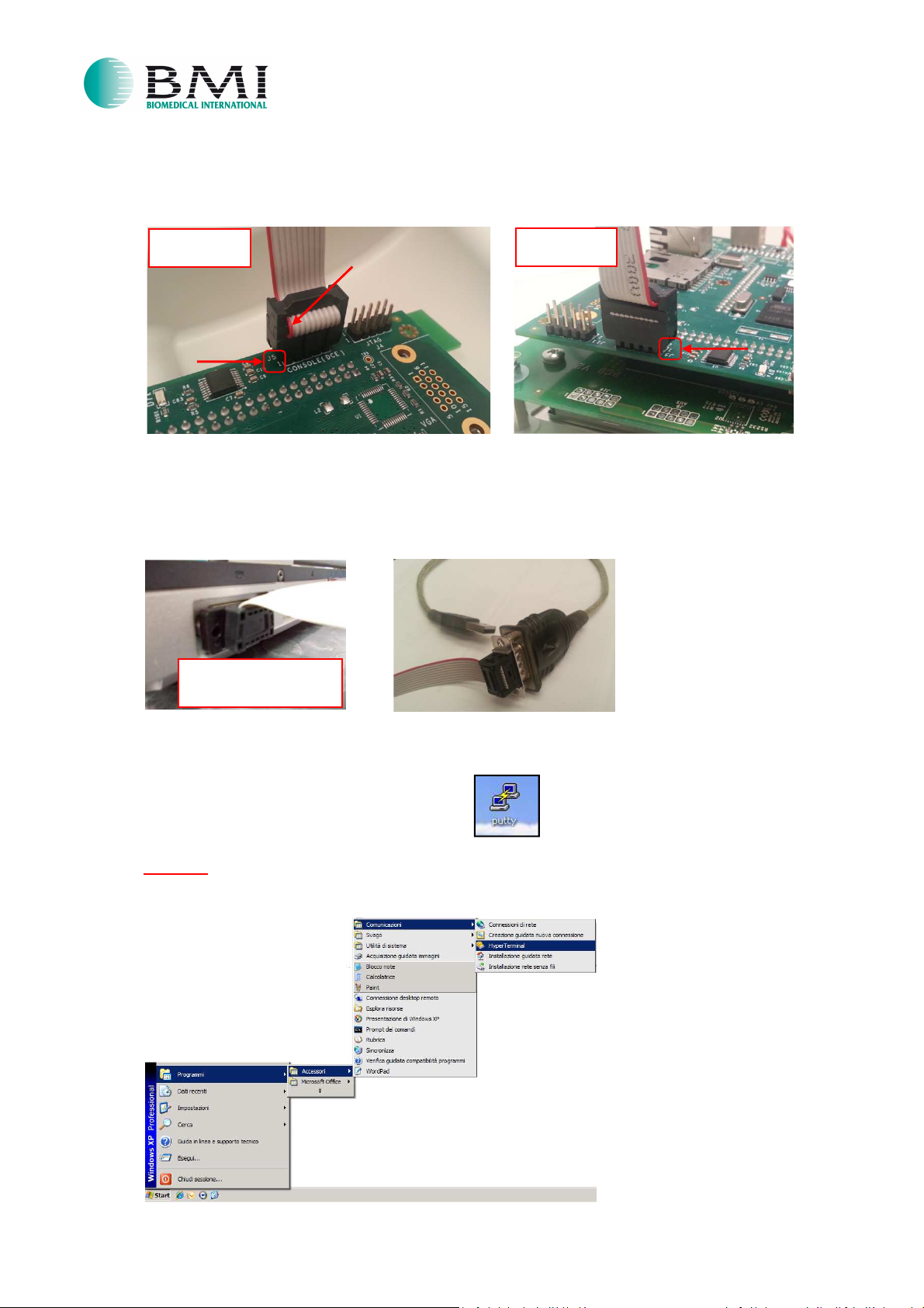
1. Make sure that serial cable between Main Board and Display Board is connected.
2. Make sure that the equipment is turned off.
3. Insert the SD CARD and put the jumper on J12 as shown in the below picture:
IMPORTANT:
while you are inserting the SD CARD, pay attention that the “Safety Lock” remains open!!
IO-28-EN Rev.2
07/05/2015
Page 3 of 17
Page 4
Front view
Rear view
with serial port
BBIIOOSS PPRROOGGRRAAMMMMAATTIIOON
N
4. Connect the flat cable to the J5 (CONSOLE), placing it in such a way that pin 1 on the flat cable
(marked in red) corresponds to the pin 1 of the J5, as shown here below:
5. Connect the flat cable to the PC/laptop, as shown here below:
- If the PC/laptop is old, it could be possible that you already have the serial port on it.
- If the PC/laptop is new, you will have to use the USB/RS232
adapter.
IO-28-EN Rev.2
07/05/2015
Example of old laptop
6. Run the software HyperTerminal for OS Windows XP, otherwise if you are using OS Windows 7
download the free program called “Putty”.
To run HyperTerminal, there are 2 ways:
First way
Click on Start, then Accessories, Communications and HyperTerminal.
Page 4 of 17
Page 5
BBIIOOSS PPRROOGGRRAAMMMMAATTIIOON
N
IO-28-EN Rev.2
07/05/2015
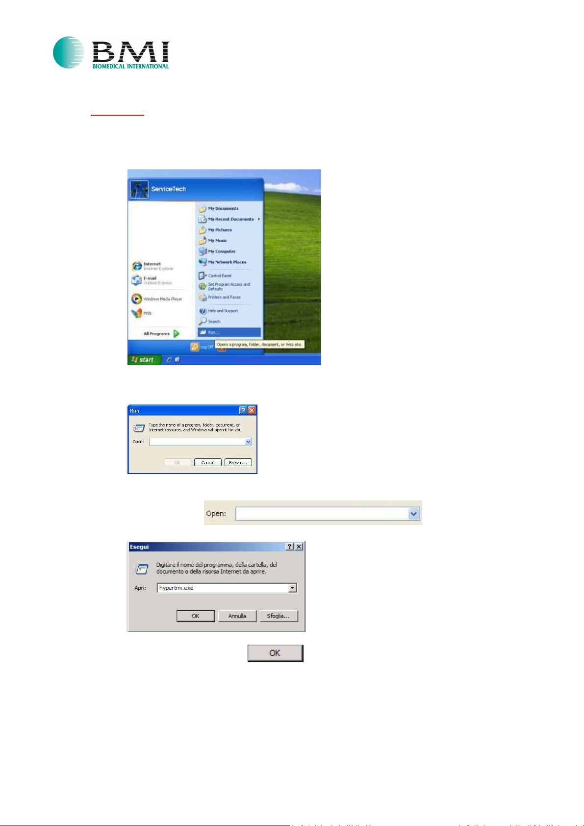
Second way
Run the software HyperTerminal in the dialog window “Run…”
o Click Start and then on Run…
o The following popup will appear:
o Write in the field the text hypertrm.exe
And confirm by clicking on
Page 5 of 17
Page 6
BBIIOOSS PPRROOGGRRAAMMMMAATTIIOON
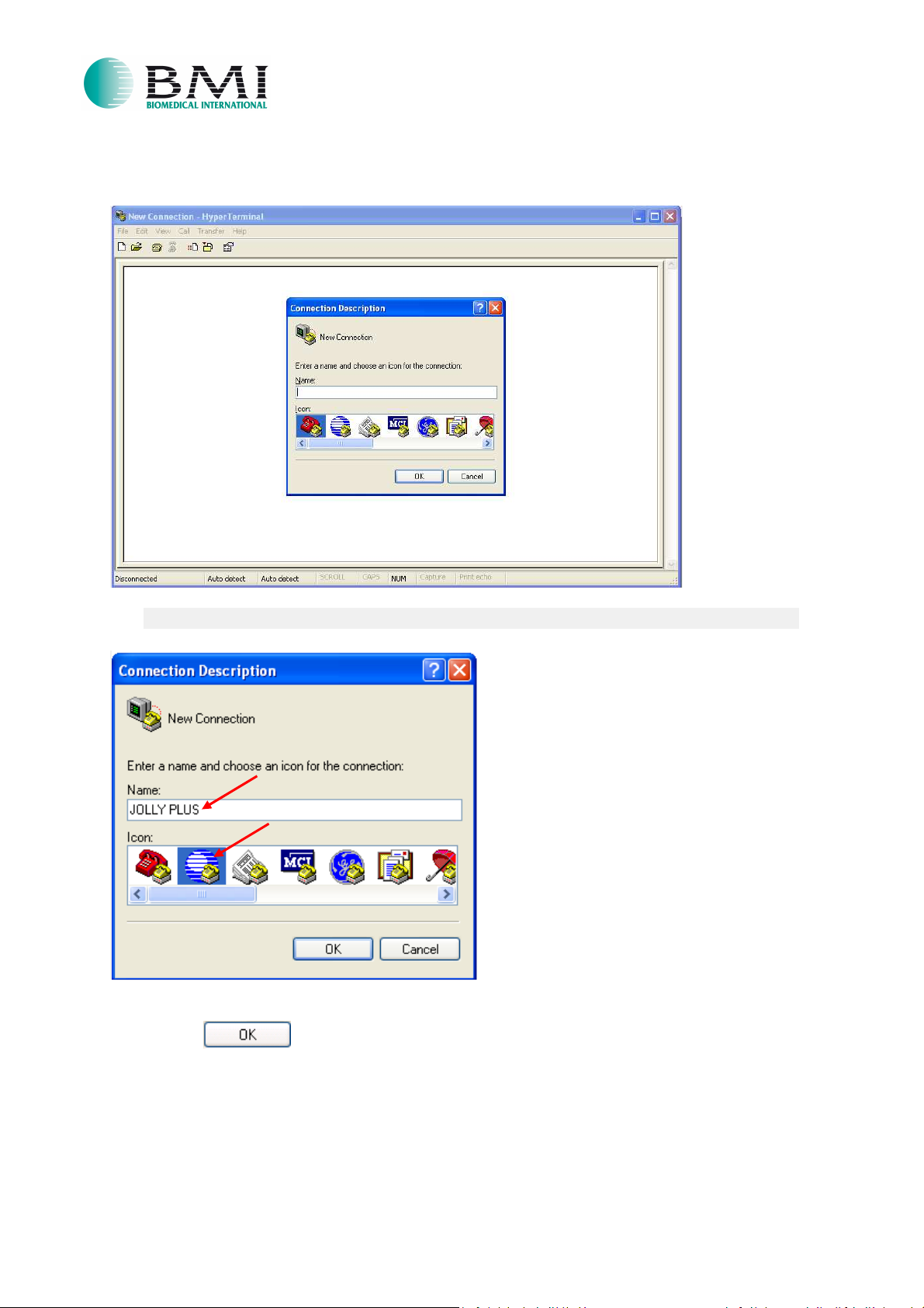
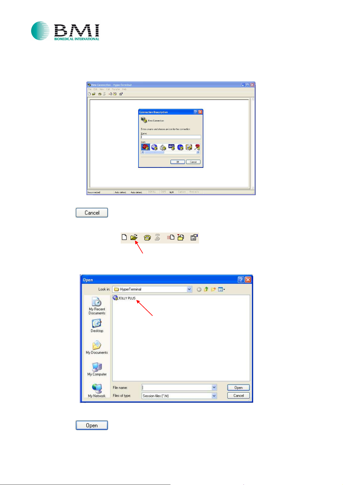
7. Once HyperTerminal is run, the following popup will appear:
N
IO-28-EN Rev.2
07/05/2015
8. Write the name JOLLY PLUS and select the preferred icon. (in this case we select the blue one)
9. Click on
Page 6 of 17
Page 7
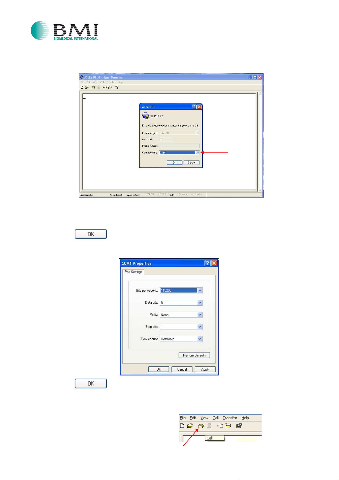
10. The following popup will appear:
NOTE:
adapter USB/RS232 be sure that you will use the correct port)
select the COM port where is connected the Display Board. (usually is the COM1, if you use an
BBIIOOSS PPRROOGGRRAAMMMMAATTIIOON
N
IO-28-EN Rev.2
07/05/2015
11. Click on
12. The following popup will appear. Set the same parameters shown below:
13. Click on
Now HyperTerminal is ready for work.
If it does not work, please check the “Troubleshoot” chapter at the end of the procedure.
If necessary, click on “Phone” icon for the “Call”:
Page 7 of 17
Page 8
BBIIOOSS PPRROOGGRRAAMMMMAATTIIOON
N
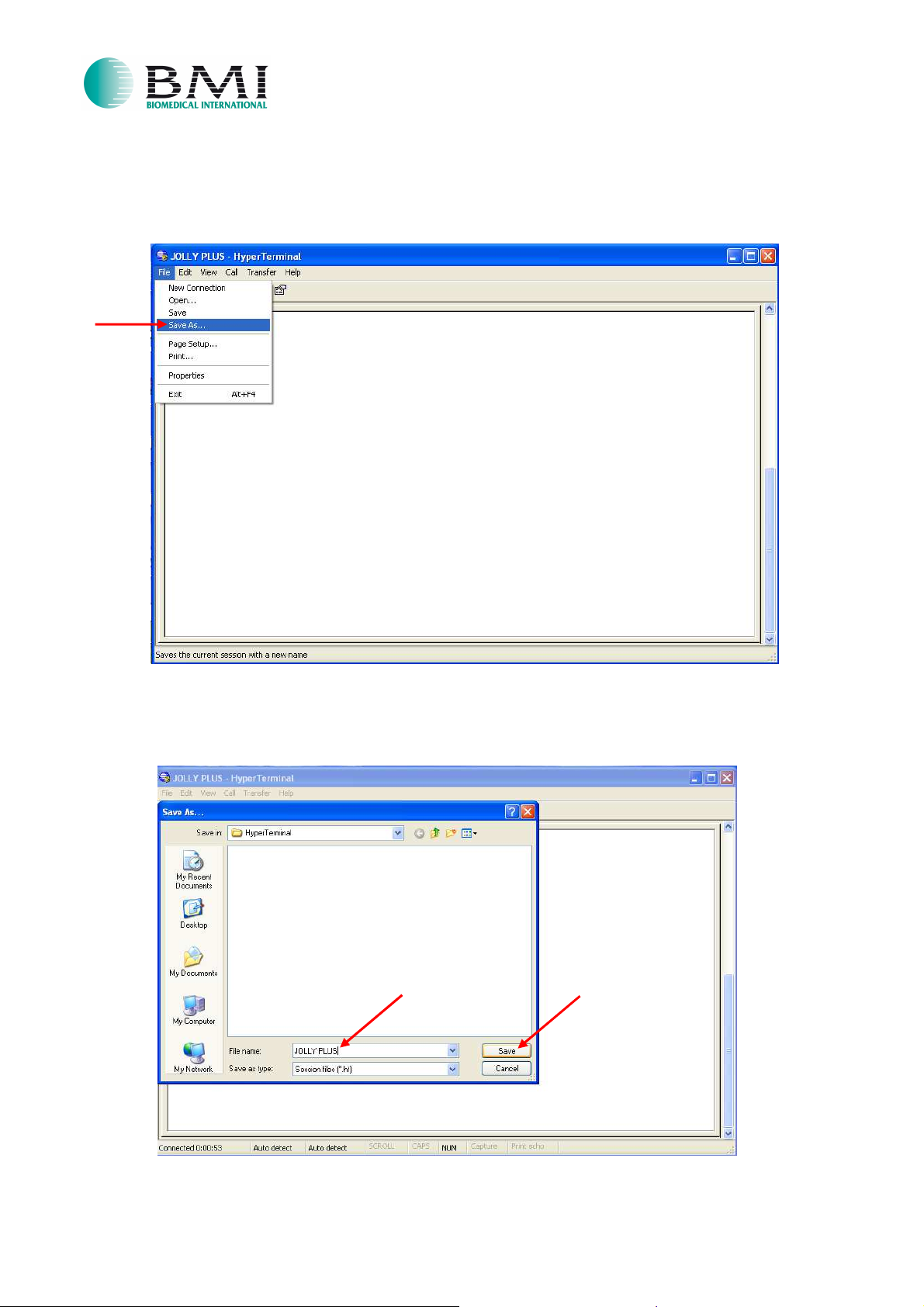
If you want to save the previous settings for a future connection, follow the below steps:
14. Click “File”, then “Save As…”
15. Save the file as “JOLLY PLUS” and then click “Save”:
IO-28-EN Rev.2
07/05/2015
Page 8 of 17
Page 9
BBIIOOSS PPRROOGGRRAAMMMMAATTIIOON
N
IO-28-EN Rev.2
07/05/2015
When you will run the next time HyperTerminal, it will be enough select the saved file JOLLY PLUS, as
shown here below:
16. Click on
17. Click on the “Open” icon
18. The following popup will appear. Select the file “JOLLY PLUS.ht”:
19. Click on
Page 9 of 17
Page 10
BBIIOOSS PPRROOGGRRAAMMMMAATTIIOON
N
IO-28-EN Rev.2
07/05/2015
Once HyperTerminal is ready for work, please proceed with the BIOS PROGRAMMATION following
the below steps:
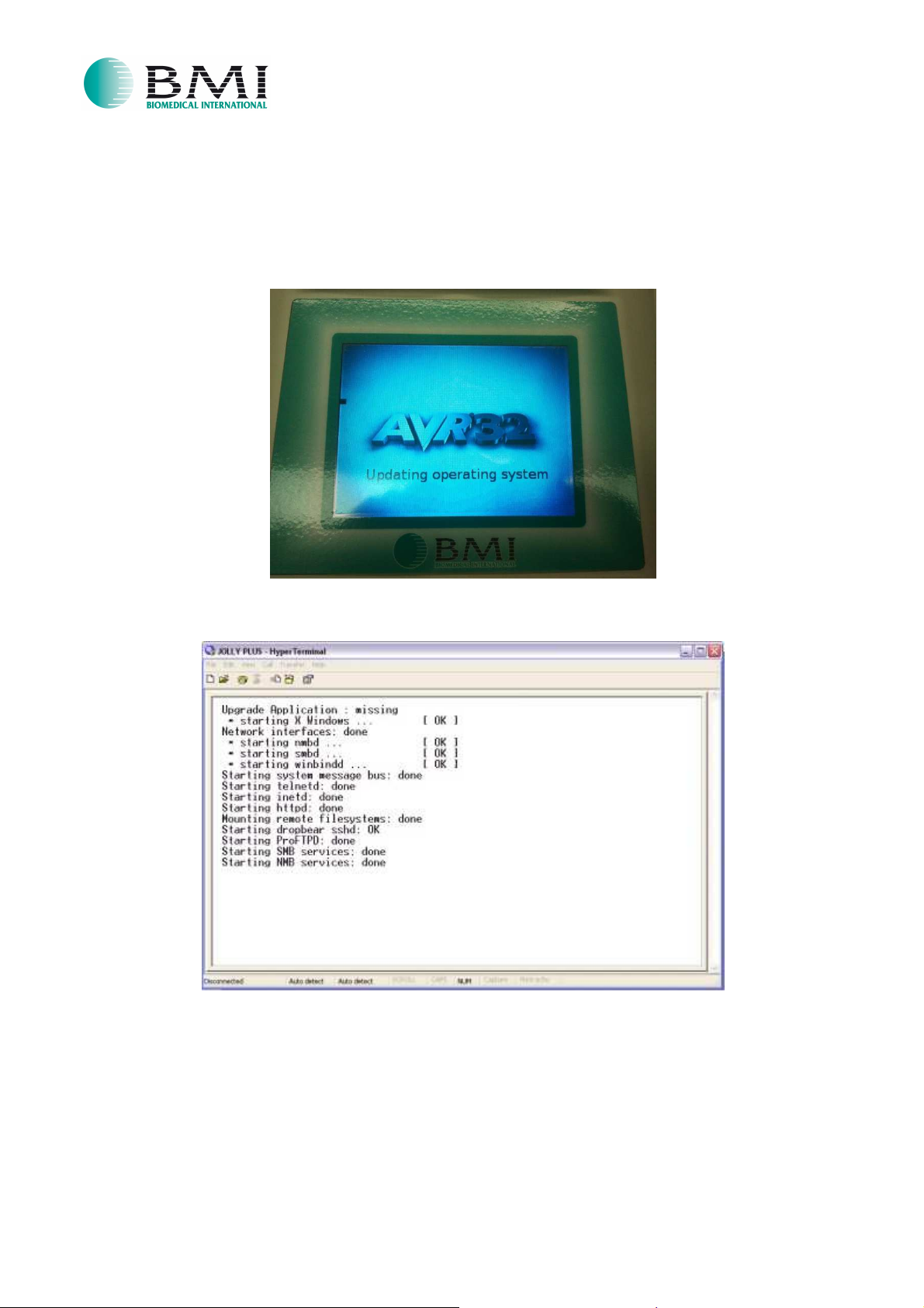
20. Turn on the Jolly Plus.
21. On the display you will see the following picture:
22. Meanwhile on the HyperTerminal window there will be the initialization messages:
Page 10 of 17
Page 11
BBIIOOSS PPRROOGGRRAAMMMMAATTIIOON
N
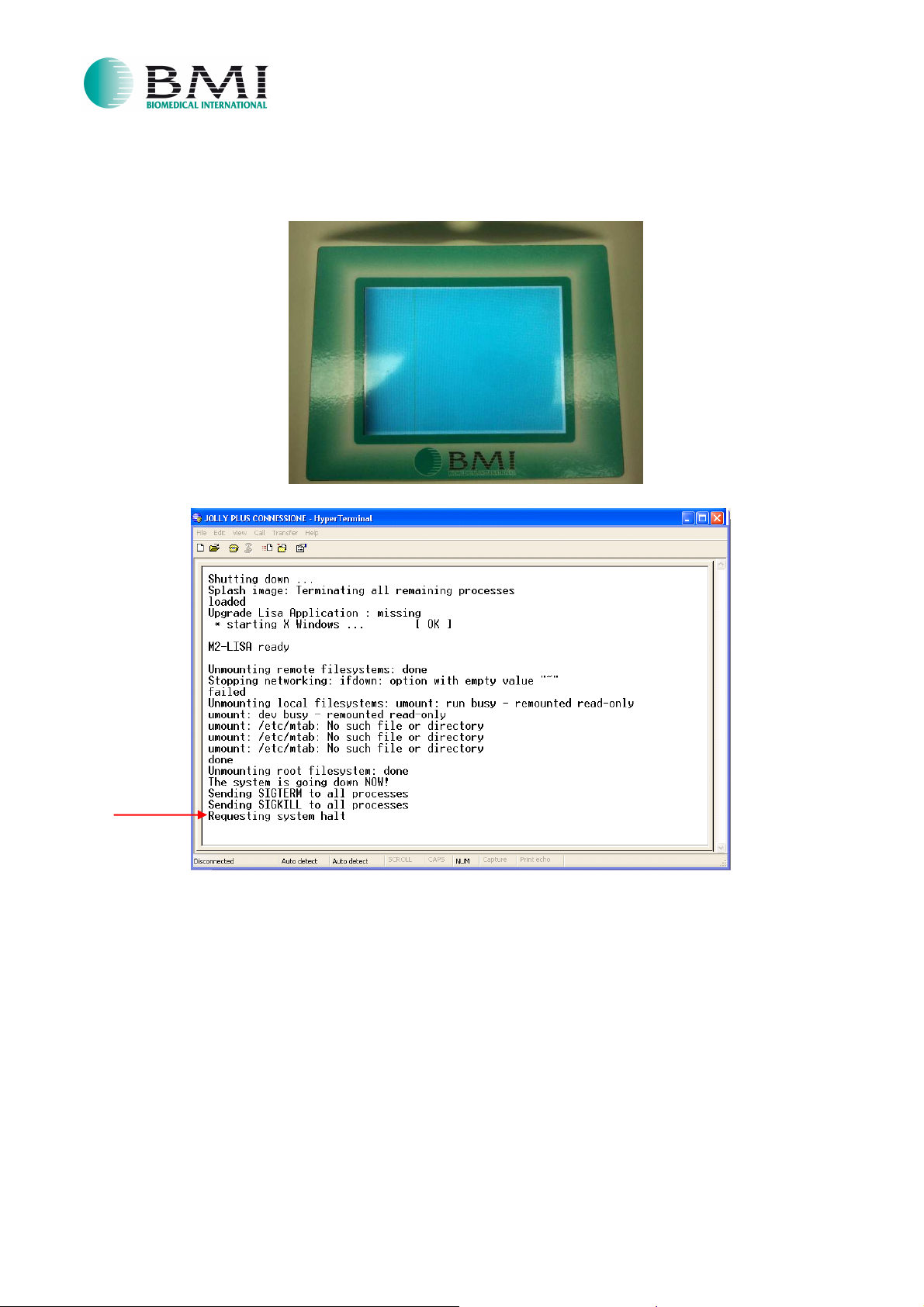
23. When the software is uploaded, you will see a white screen on the display and you will have a
request of halt on the HyperTerminal window:
24. Turn off the Jolly Plus.
IO-28-EN Rev.2
07/05/2015
Page 11 of 17
Page 12
BBIIOOSS PPRROOGGRRAAMMMMAATTIIOON
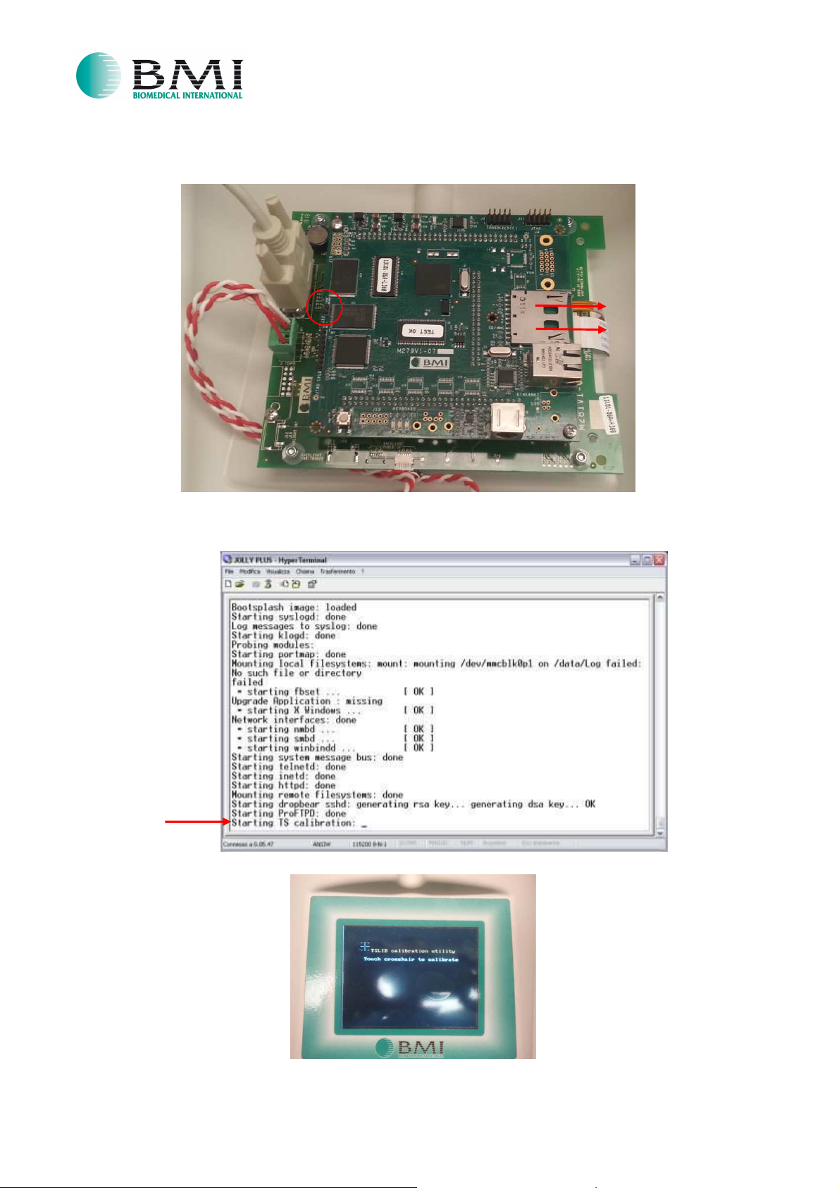
25. Remove the SD CARD and the jumper as shown in the following picture:
26. Turn on the Jolly Plus.
27. Wait until on the HyperTerminal window appears “Starting TS calibration”:
N
IO-28-EN Rev.2
07/05/2015
28. Make the “touch screen calibration”. (follow the reference point – cross on the display)
Page 12 of 17
Page 13
BBIIOOSS PPRROOGGRRAAMMMMAATTIIOON
N
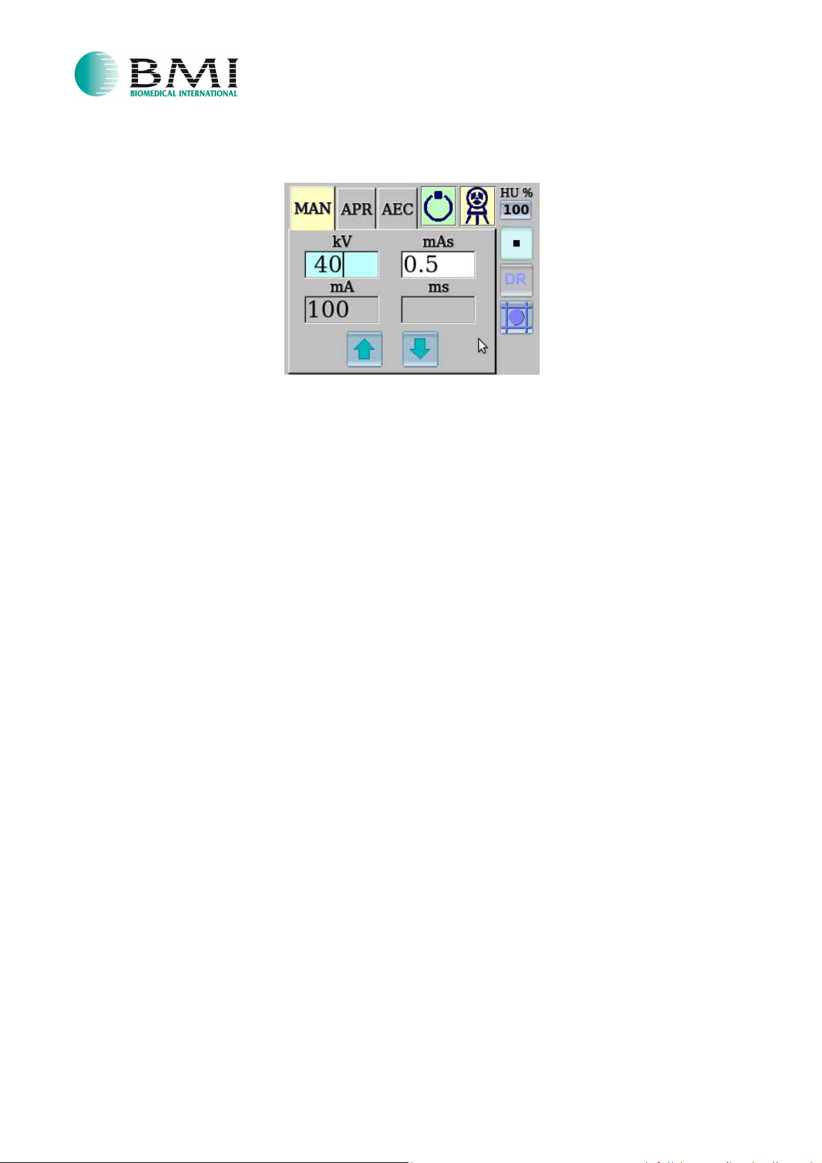
29. When the “touch screen calibration” will end, it will appear the “Operator Mode”:
ATTENTION: Do not turn off the equipment before the end of the flash memory scan.
This verification must be done through HyperTerminal.
During the scan, on the HyperTerminal window you will see:
Running first-boot configuration.
This may take a minute.
/usr/share/fonts: caching, new cache contents: 0 fonts, 8 dirs
/usr/share/fonts/100dpi: caching, new cache contents: 398 fonts, 0 dirs
/usr/share/fonts/75dpi: caching, new cache contents: 398 fonts, 0 dirs
/usr/share/fonts/OTF: caching, new cache contents: 23 fonts, 0 dirs
/usr/share/fonts/Speedo: caching, new cache contents: 0 fonts, 0 dirs
/usr/share/fonts/TTF: caching, new cache contents: 34 fonts, 0 dirs
/usr/share/fonts/Type1: caching, new cache contents: 29 fonts, 0 dirs
/usr/share/fonts/cyrillic: caching, new cache contents: 0 fonts, 0 dirs
/usr/share/fonts/misc: caching, new cache contents: 59 fonts, 0 dirs
/usr/X11R6/lib/X11/fonts: skipping, no such directory
//.fonts: skipping, no such directory
/usr/var/cache/fontconfig: cleaning cache directory
//.fontconfig: not cleaning non-existent cache directory
/usr/bin/fc-cache: succeeded
If appears the text "/ usr / bin / fc-cache: succeeded", it means that the scan is finished
successfully. As final confirmation, you will also see the automatic boot of the software.
If you encounter some problems, it will appear messages similar to the following:
UBIFS error (pid 538): do_readpage: cannot read page 0 of inode 15524, error -117
UBIFS error (pid 538): ubifs_check_node: bad CRC: calculated 0x7a70701c, read 0x2d213b4b
UBIFS error (pid 538): ubifs_check_node: bad node at LEB 1009:107192
UBIFS error (pid 538): ubifs_read_node: expected node type 1
UBIFS error (pid 538): do_readpage: cannot read page 0 of inode 15524, error -117
In this case you should re-insert the SD CARD and repeat the installation procedure from step 1.
IO-28-EN Rev.2
07/05/2015
Page 13 of 17
Page 14
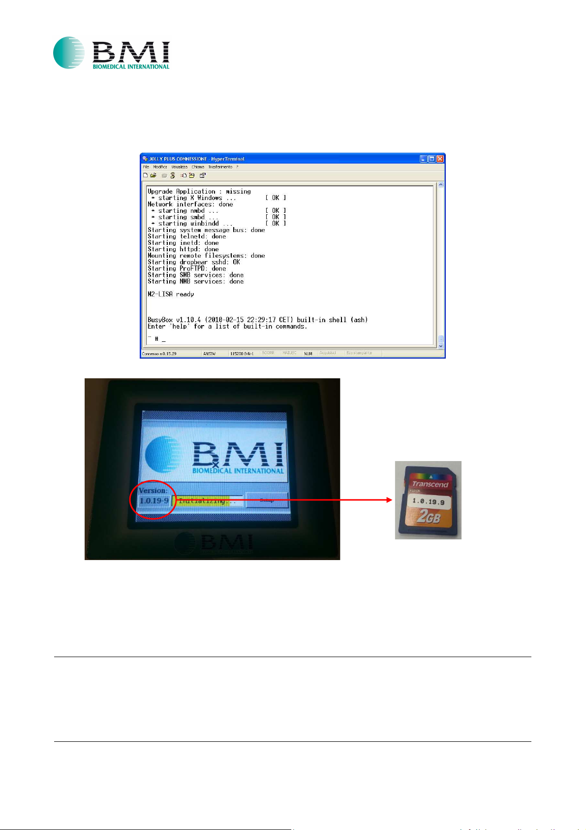
30. Wait the booting of the software (the system will restart automatically) and check that the Version
written on the SD CARD is the same version displayed during the “Initializing” process, as shown in
the below pictures:
BBIIOOSS PPRROOGGRRAAMMMMAATTIIOON
N
IO-28-EN Rev.2
07/05/2015
Post-Programming phase
Be sure that Jolly Plus is turned off and reassemble mechanically.
ATTENTION:
phase” chpt, option 2 - point C)
Connect it only when the unit is turned off.
Do not connect the “Binder” connector if the device is powered. (see “Pre-Programming
Page 14 of 17
Page 15
BBIIOOSS PPRROOGGRRAAMMMMAATTIIOON
N
IO-28-EN Rev.2
07/05/2015
Troubleshoot
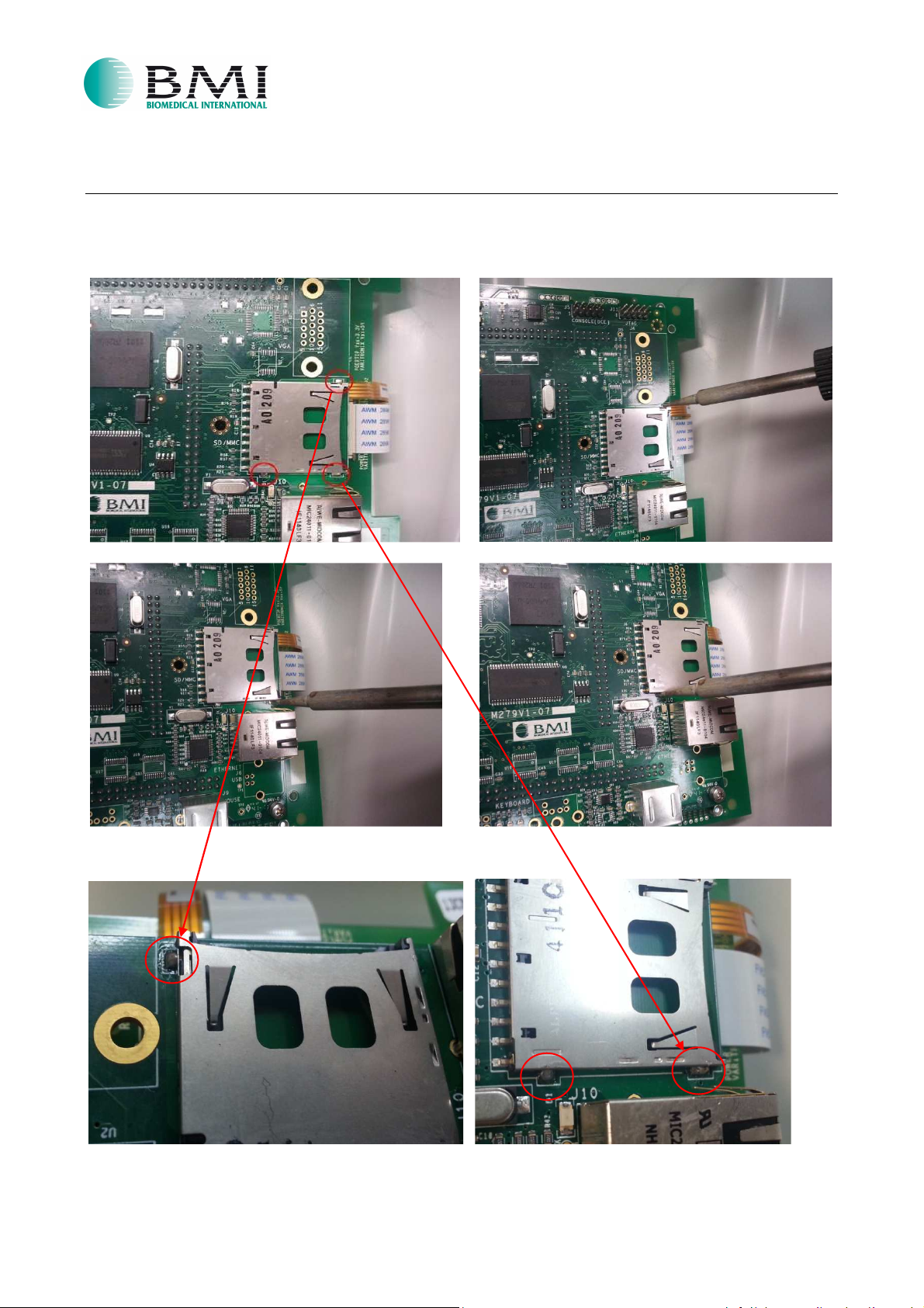
If you will face any problem during the BIOS upload and for any reason it will not end correctly, it is
recommended to solder the plots around the SD CARD slot as shown in the below pictures and remake all
the procedure from step 1:
Page 15 of 17
Page 16
BBIIOOSS PPRROOGGRRAAMMMMAATTIIOON
N
IO-28-EN Rev.2
07/05/2015
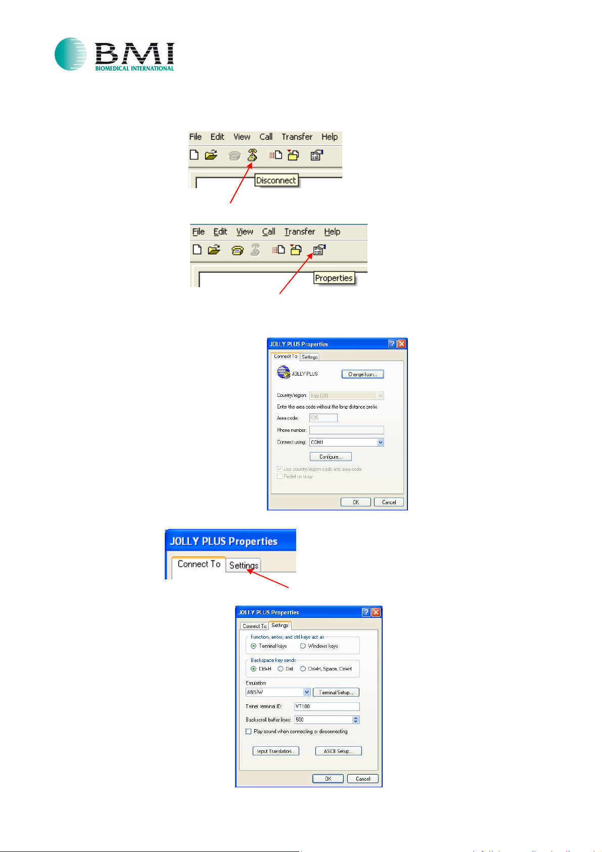
Instead, if you have a communication problem between PC and Display: (you do not see correctly the texts)
a. Click on “Disconnect”:
b. Click on “Properties”:
c. The following popup will appear:
d. Select “Settings”:
e. The following popup will appear:
Page 16 of 17
Page 17
BBIIOOSS PPRROOGGRRAAMMMMAATTIIOON
N
IO-28-EN Rev.2
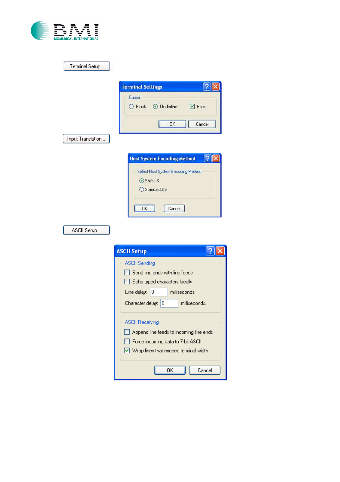
f. Click on and verify that all the settings are like in the following picture:
g. Click on and verify that all the settings are like in the following picture:
07/05/2015
h. Click on and verify that all the settings are like in the following picture:
i. If you found some difference in what above reported, then you must set all the parameters like in the
previous pictures and after you must turn off and then turn on the Jolly Plus (restart the unit).
Otherwise, if there are no differences, with big probability there are failures in the flat cable or in the
serial port configuration.
Page 17 of 17
 Loading...