


www.bmc-racing.com
timemachine
OWNERS MANUAL
ENGLISH

timemachine
OWNERS MANUAL
Owners Manual – english

Introduction
Positioning
How to measure your position
Determine the right frame size and configuration
Seat post hardware position
Frameset overview
Building a timemachine
Recommended tooling
Recommended procedure
Frame preparation
Di2 specific parts
Parts to check
Brakesets
Assembling the brake arms
Brake cable routing (front)
Installing the pipe on front brake
Brake cable routing (rear)
Cable tension (front brake)
Cable tension (rear brake)
Brake pads setting
Di2 shifting
Cable routing
Handlebar specifics
Mechanical shifting
Cable routing
Hingefork and headset
Headset parts over view
Assembly procedure
P2p stem system
Headset parts over view
Assembly procedure
P2p seatpost
Seat post clamp
Service instructions
Washing your bike
Troubleshooting
CONTENTS
Owners Manual
3
5
5
8
10
11
13
13
14
14
14
15
16
16
18
19
19
21
22
22
24
25
27
27
27
29
29
29
31
31
32
33
33
35
35
37
Contents

BMC timemachine frame and components are designed as a system to provide a very high level of aerodynamics and riding
performance. Adjustability was not in any way compromised and the timemachine offers the highest adjustment possibility ever built
into a fully integrated time trial bicycle.
Adjustability being a key part of the system’s performance, it is necessary to understand that most components of the frameset
have been designed specifically for timemachine and their function may slightly differ from your traditionnal road bike “off the shelf”
components.
BMC timemachine uses all the latest and most high-end technologies that can be found in bicycle manufacturing, including sharp edged
and thin-walled carbon fiber composite construction, which should be treated with delicacy from the end user to prevent permanent
and sometimes invisible damage.
For the reasons mentioned above, we ask you to carefully follow the instructions provided in this manual.
Incorrect mechanical operation on your bicycle could lead to serious damage, which could cause you to fall and lead to injury
or death.
If you do not have the appropriate tools or experience to execute the following instructions, or if you need further information,
please contact your official BMC dealer for service of your bicycle.
Introduction
Introduction
2 | 3
Introduction

A bicycle rider will only perform at his best if he is correctly positioned on his bike, especially for time trial and triathlon competitions.
The following instructions are simple guidelines to help you decide which size and which stem configuration to choose in order to reach
a given handlebar position. We do not in any way provide you with a fitting tool, those instructions can only help you once your position
is defined. If you wish to change the position from your previous bike or if the timemachine will be your first time trial bike, we highly
recommend you to visit a professional fitting expert.
Many different handlebar types and shapes are available on the market and it is not possible for BMC to guarantee accurate positioning
for all of them. The handlebars provided with the TM01 complete bikes were carefully selected to offer the highest adjustment possibilities
in a light, reliable and user-friendly package. Therefore we suggest you should use the original timemachine handlebars and carefully
follow the instructions.
Positioning
In best case you already have a bike adjusted to your desired position. If there is any doubt for you regarding which position you should
use, we highly recommend you to visit a professional fitting expert, who will be able to give you the required data.
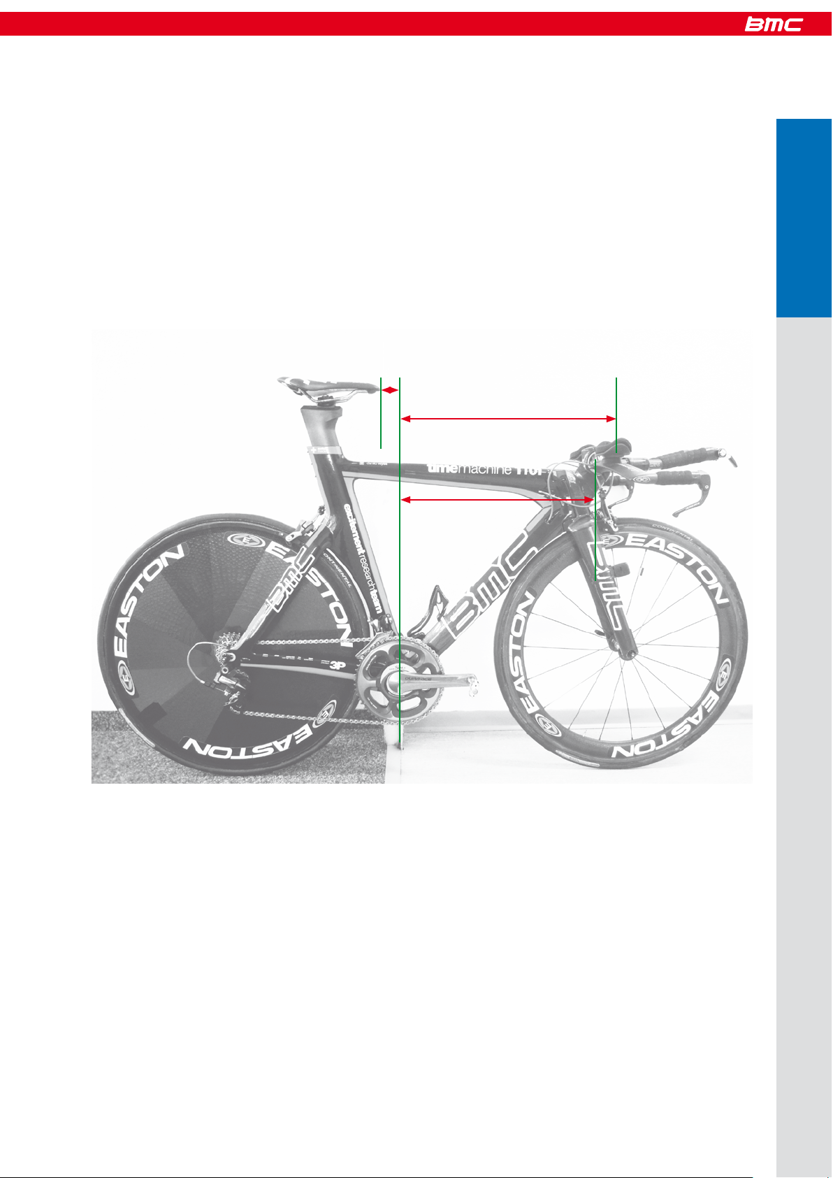
To dete rm ine the r igh t fr am e s iz e, stem and sea tp ost hard wa re po sit io n, th e f ollo wing mea su re men ts ar e re qu ired :
- stack (SP) and reach (RP) to the pads of your bars (Figure 1 and 2)
- stack (SS) and reach (RS) to the center of the handlebar clamp of the stem (Figure 1 and 2)
How to measure your position
Figure 1
Figure 2
4 | 5
Positioning
Positioning

- stack (SB) and reach (RB) of your bars (Figure 3a and b)
Figure 4
Figure 3a
- seatback to the saddle tip, valid for all Arione and SLR saddles (SB)
- vertical seat height to the top of the saddle (VSH)
- BB height (BBH)
Figure 3b
Positioning

To take those measurements, the easiest way is to place your bike on a even, horizontal ground and lean it against a vertical edge (for
example a corner of a wall, a pole or a door case) and align it so the edge is centered on the bottom bracket axle.
Then follow this procedure (picture):
- Measure the vertical distance between the BB axle center and the ground (BBH).
- Measure the vertical distance between the ground and the top of the saddle (VSH).
- Measure the vertical distance from the ground to the middle and upper surface of the bar pads (SP).
- Measure the vertical distance from the ground to the center of the handlebar clamp (SS).
- Measure the horizontal distance from the edge your bike is leaning against to the center of the pads (RP).
- Measure the horizontal distance from the edge to the center of the handlebar clamp (RS).
- Measure the horizontal distance from the edge to the tip of your saddle (SSB) (Figure 5).
Figure 5
Example: how to measure the reach on your old bike
6 | 7
Positioning
RP
RS
SSB
Positioning

For frame size and stem configuration, it is important to calculate the SSnew and RSnew values that your timemachine will be to.
All dimensions are in millimeters!
Determine the right frame size and stem configuration
You intend to use: Please calculate:
You r ol d ba rs on new TM
SSnew = SS - BBH
RSnew = RS
Standard TM bars (Profile)
SSnew = SP - 60 - BBH
RSnew = SP + 20
Any other new bars
SSnew = SP - SB - BBH
RSnew = RP + RB
Once you know your SSnew and RSnew:
Place the SS and RS values in the chart (Figure 6) onto the horizontal and ver tical.
The chart shows the various handlebar center positions you can achieve on TM01.
Check which point comes closest to the position you have calculated.
The color shows the frame size, the number is a reference to the stem configuration. All the stem configuration are listed in the second
chart (Figure 7).
The Profile aero bars specified on the complete bike offer additional pad adjustment, so you will be able to reach your desired position
even if the position you choose to build is some millimeters away from the calculated values.
You can use the tool on our homepage.
Measure SB and RB on your new bars
Measure SP, RP and BBH on your old bike
Stack and Reach BB to Handlebar Clamp
Figure 6
SSnew
RSnew
Positioning

Figure 7
stem configuration
1
2
3 4
5 6 7 8
9 10
11 12
13
17
21
25
29
14
18
15 16
19 20
24
2322
26
30
27
31
28
32
8 | 9
Positioning
Positioning

To dete rm ine the r igh t po si tion of the s eatp os t h ar dwa re , y ou ne ed t o k now SB an d S H.
- You can measure SB on your previous bike
- Use SH = VSH - BBH
Then place the SSB and SH values in the chart below. The point thus created will fall into a colored zone. The color code will then
indicate where to mount the saddle hardware.
Seat post hardware position
SSB (saddle seat back)
Color code
Positioning
SH (vertical seat
height from BB))

Frameset overview
10 | 11
Frameset
Page 33
Page 31
Page 29
Page 15
Page 17
Page 16
Frameset overview

A timemachine frameset or complete bike includes proprietary components such as brakes, fork, headset, stem, seat post … For each
of those components, you will find part numbers, service and assembly instructions detailed in the next chapters of this manual.
Building a timemachine
Before you start assembling, make sure you are equipped with the following tools:
- Allen keys: 2mm, 2.5mm, 3mm, 4mm, 5mm
- Ratchet wrench with 8mm allen socket
- Flat wrench 9mm, 13mm
- Red Loctite 271
- Grease gun or grease brush
- Wire cutter pliers
- Long reach pliers
- A black marker pen
- Electrical tape
- 1 extra shifting cable
- Heat gun or hair dryer
- Torque wrench with 4, 5 and 8mm allen heads sockets
- Carbon friction paste
- Bike stand with fixation for frame and fork
Recommended tooling
12 | 13
Building
Building a timemachine

1 Frame preparation Refer to page 14, install rear wheel adjusters
2 Mount the brake arms in frame Refer to page 15
3 Rear brake cable routing Refer to page 19
4 Shifting cable routing Non Di2: Refer to page 27
5 Shifting cable routing Di2: Refer to page 25
6 Derailleur, front and rear Refer to manufacturers instructions
7 Fork and headset Refer to page 29
8 Stem Refer to page 31
9 Handlebars Di2: Refer to page 27
10 Front brake cable routing Refer to page 18
11 Install the pipes on brake cables Refer to pages 19
12 Brake cable tension front and rear Refer to pages 21 and 22
13 Mount wheels and brake pads Refer to page 22
14 Bolt on stem cover For TM01: Refer to page 36
15 Install top tube cable guide Only for TM02
16 Seat post installation Refer to page 33
17 Crankset Mount the crank set once the rear brake is properly set
18 Chain Refer to manufacturers instructions
19 Gears Adjust the shifting, refer to manufacturers instructions
20 Bar tape Wrap the bar tape as a final step
If you are building a timemachine frameset from scratch, the most convenient way is to follow the order and the procedure described
below. This is only the global procedure, all the seperate steps and recommendations are described one by one in the next pages of
this manual.
Please go through all the instructions before starting the assembly of the frameset.
Recommended procedure
FD cable stopper for mechanical groupset
Part N° 210995
Frame preparation
Di2 specific parts
When the frameset is built with Shimano Di2 groupset, replace the front derailleur cable stopper by the special cover
(highlighted in blue).
Cover for Di2 groupset
Part N° 210996
Building a timemachine

Before assembling the frame, it is important to check
- RD hanger bolts should be well tightened with 2mm Allen key.
- Brake bosses should be mounted and tightened with red Loctite (when new, the par ts are prepared at the factory).
- Timemachine frames are equiped with wheel adjusters at the rear dropout. Use the nuts to properly align the rear wheel into the frame.
Description Part N°
1 Derailleur hanger & bolts 210544
2
Axle adjuster 210545
- The nut should be placed so that the O-ring seal is facing towards the hub.
1
2
15 | 16
14 | 15
Building
Building a timemachine

Brakesets
The timemachine is equiped with custom brakes which are only available for this specific model from BMC. The function and installation
are different from what you may be used to on less integrated road bikes.
We ask you to carefully read and follow the instructions in order to avoid misuse.
Assembling the brake arms
Description Part N°
Brake kit (all parts) 210534
1 Brake arms (front)
2 Springs
3 Brake bosses 210541
4 Brake bolts
5 Brake stoppers 210540
6 Brake cover 210525
7 Pipe 210538
8 Pipe holder 210539
- Grease should be applied on the brake bosses and springs, and red Loctite on the brake arm bolts.
Longest extension of the spring
should point out of the brake
arm.
2
3
1
1
5
7
6
2
4
3
8
Building a timemachine

- The arms should be tightened in “open position”, and then place the stoppers to maintain them in position.
Tor qu e 4 .5 N m
- Each brake arm should operate smoothly from the stoppers position.
- Front and rear brake arms have a different shape, but function and installation are the same.
Description Part N°
Rear brake set 210535
1 Springs
2 Brake arms
3 Brake bolts
4 Brake stoppers 210540
5 Pipe 210538
6 Pipe holder 210539
4 5
6
7
16 | 17
Building
1
2
3
4
65
Building a timemachine

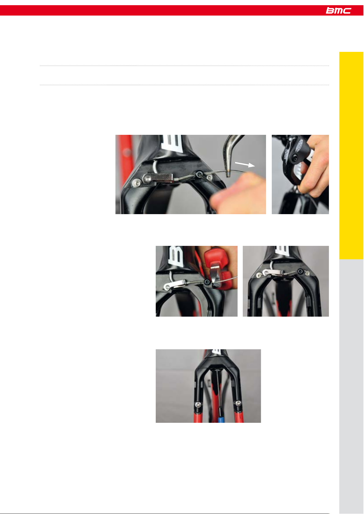
Brake cable routing (front)
- Run the brake cable in the bars (1), and then inside the fork (2), either on left or right hand side depending on how you run your brakes.
- Use the cable as guide to slide in the housing (3). Pull on the cable until the housing sits well in the brake lever (4).
- Mark where the housing exits the fork (5), then take it out of the fork and cut it shorter 15mm from the mark (6).
Reinstall the housing into the fork, using the cable as guide.
To ha ndl eb ar s
1 2
3 4
5
6
Building a timemachine

Installing the pipe on front brake
- Always run the housing of the pipe onto the cable first (7), then run the cable into the metallic pipe (8). Pull the cable until the
housing sits well inside the pipe (9).
- Install the pipe holder while running the brake cable through the brake arm.
Brake cable routing (rear)
- Run the rear brake cable inside the bars (1) and then the frame, entering the top tube with the cut end of the cable (2).
98
7
10
1
2
18 | 19
Building
Building a timemachine

- Installing the pipe: Always run the housing of the pipe onto the cable first (6), then run the cable into the metallic pipe (7). Pull the
cable until the housing sits well inside the pipe.
- Install the pipe holder while running the brake cable through the brake arm (8).
- Use the cable as guide to slide in the cable housing (3).
- Remove the cable and cut the housing at the exit of the frame, below the BB (5).
3 4
5
6
7
8
Building a timemachine
- When you clamp the cable (2.5mm Allen), maintain the brake arms against the stoppers, and apply tension to the brake cable (1). Once
the cable is tight, check the function of the brake lever (2). There should not be play in the lever and the brake arms should come
back all the way to the stoppers. Repeat operation if needed.
- Cut the cable against the brake arm by removing the brake stopper (3).
- Bolt on the brake cover (only the front brake has a cover).
Cable tension (front brake)
It is important to understand that cable tension is independent from the position of the brakes. It means you cannot adjust the brake pad
reach by adjusting cable tension. The reach of the pads is adjusted directly on the pads with spacers.
1
2
3
4
5
20 | 21
Building
Building a timemachine

- Maintain the brake arms against the stoppers, apply tension on the cable and clamp the cable (1). Once the cable is tight, check the
function of the brake lever. There should not be play in the lever and the brake arms should come back all the way to the
stoppers. Repeat operation if needed.
Cable tension (rear brake)
- Cut the cable 40mm away from the brake arm (1), then clip the cable back into the down tube (3).
To mount various rim dimensions, and also to compensate pad wear, the reach of the brake pads needs to be adjusted with spacers.
Please refer to your wheels manufacturers instructions regarding which brake pad compound you should use.
Brake pads setting
Exemple: Pads fully in and fully out:
1
2
3
Building a timemachine

Recommended spacer installation (with new brake pads):
Description Part N°
Front pad set 210536
Rear pad set 210537
1 Brake pad
2 Socket
3 0.5mm spacer
4 1.2mm spacer
5 2mm spacer
6 Brake pad bolt
Rim width Spacers (per side)
Zipp 808 26 -1.5 ( pads gr in de d)
23 0
22 0.5
21 1 = 0.5 + 0.5
Easton /
Shimano
20.6 1.2
19.6 1.7 = 1.2 + 0.5
Mavic (standard
alloy wheels)
19 2
18.6 2.2 = 1.5 + 0.5 + 0.5
18 2.5 = 2 + 0.5
3 different spacers are delivered with the bike:
0.5mm (x2), 1.2mm, 2mm
22 | 23
Building
1
2
564 3
Building a timemachine
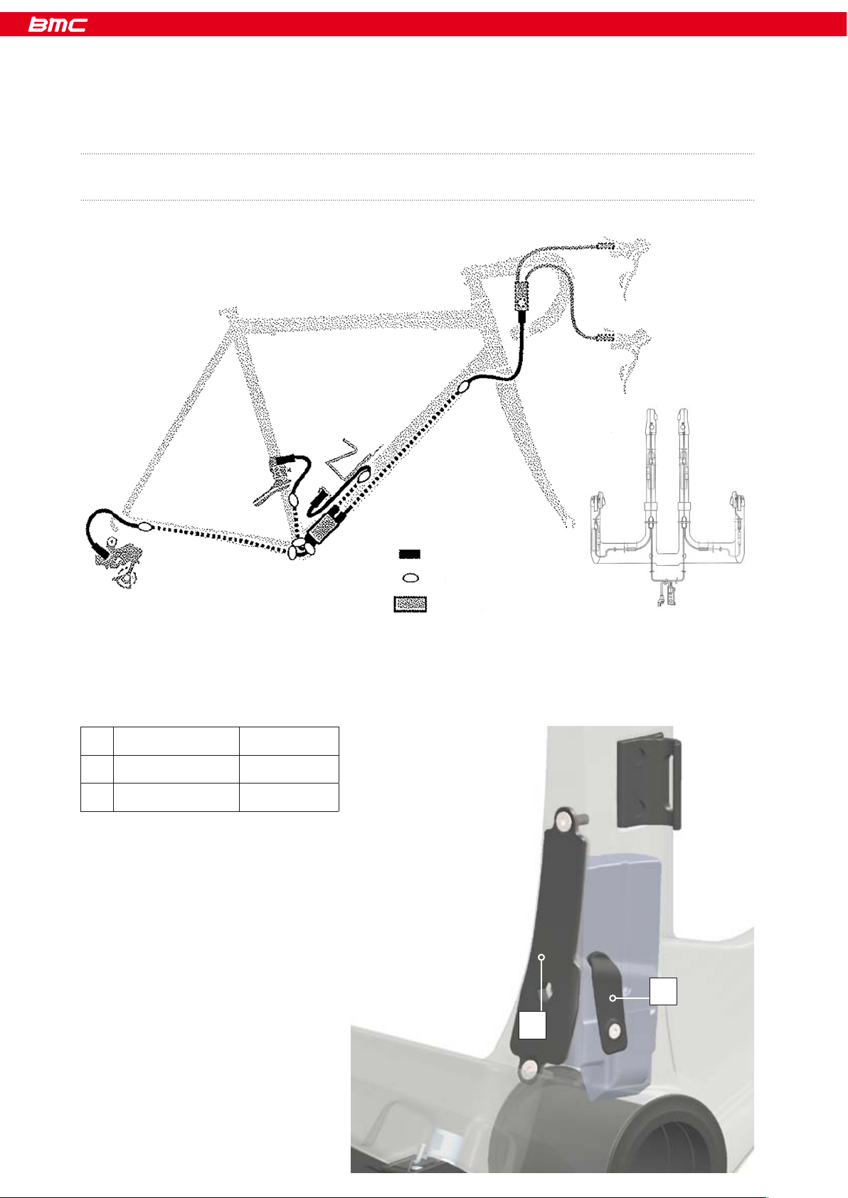
The following instructions will help you to install the Di2 cables inside the timemachine frame, it will not guarantee a proper function of
your groupset.
Therefore, before installation, we recommend you to read the instructions provided by Shimano.
Description Part N°
1 Battery cover 210543
2 Cable stop cover 210996
Di2 shifting
The timemachine frameset is 100% compatible and retrocompatible with mechanical (Shimano, Sram and Campagnolo) and electronic
(Shimano) groupsets.
Connector
Hole
Junction (SM-JC41)
1
2
Building a timemachineBuilding a timemachine

Cable routing
- Use a shifting cable as guide to insert the rear derailleur wire (3). Enter from the drop out (1) and exit on top of the BB (2).
- Use a shifting cable as guide (5) to insert the wire from the junction to the handlebars. Enter over the BB towards the head tube (6).
- Insert the front derailleur wire.
- Bolt the battery support onto the battery cover (8) and install the battery (9) (battery charged).
1
2
3 4
5
6 7
8
9
24 | 25
Building
Building a timemachine

- Connect all wires to the junctions (10), use the heat gun to seal the connections (11).
- Push the junction and the wires inside the downtube of the frame, using the 9mm wrench (12).
- Bolt the battery cover onto the frame (13), install rubber grommet (14).
10
11
12
13 14
Building a timemachine

The timemachine frameset is 100% compatible and retrocompatible with both mechanical (Shimano, Sram and Campagnolo) and
electronic (Shimano) groupsets.
The following instructions will help you to install the shifting cables inside the timemachine frame, it will not guarantee a proper function
of your groupset.
Therefore, before installation, we recommend you to read the instructions provided by the manufacturer of your groupset.
Mechanical shifting
Please note:
The cable routing uses full housing from handlebars to rear derailleur, and full housing from shifting lever to front derailleur cable stopper.
Cable routing
Handlebars specifics
It is possible to cleanly integrate the Di2 wires into the handlebars delivered with the timemachine complete bikes.
Refer to Shimano documents to position the cables.
- Place the frame vertical, drop outs on top. Enter at the drop outs (1), run the cable over the BB (2) and push towards head tube (3).
Use a cable to guide the rear derailleur housing (4 and 5).
1
2 4
3
5
Red
Green Yel lo w
White
26 | 27
Building
Building a timemachine

- Use a shifting cable (6) to guide the front derailleur cable housing (7). Exit below the BB at the down tube window. Insert a nosed end
cap on the extremity of the cable housing (8).
- Let the cable do a loop (9) and run the cable through the cable stopper (10). Then pull the housing (11) until the nosed end cap is fully
in the cable stopper (12).
Pull from
head tube
Hold the cable
876
9
10
11
12
Building a timemachine

Hingefork and headset
Parts overview
- Apply grease on the bearing seats (1) and all metal parts (2). Install bearings and crown races (3).
Assembly procedure
Description Part N°
1 Hingefork 210510 (S Red)
210511 (M Red)
210512 (L Red)
210799 (S Blue)
210800 (M Blue)
210801 (L Blue)
2 Steer tube 210527 (S)
210528 (M)
210529 (L)
3 Bearings 210994
4 Lower crown race 210526
5 Upper crown race 210526
6 Slotted sleeve 210526
7 Top c ap 210526
8 Headset bolt 210526
9 Stem cover 210524
1
2 3
28 | 29
Building
1
2
3
4
5
6
7
8
9
Building a timemachine

- Slide the fork on top of the crown race (4) and insert the steer tube from the bottom up (5). Tighten the steer tube to 8 Nm with 8mm
Allen ratchet wrench (6).
- Push in slotted sleeve (7), install top cap and bolt. Tighten lighly to preload the bearings (8).
- Lightly tighten the fork clamp (9) (4mm Allen, max torque 2.0 Nm).
4 5 6
7
8
9
Building a timemachine

- Each stem element can be flipped 180° to shift position.
- It is possible to use 1, 2 or none of the length spacers.
- There are 2 angles provided with the stem, it is not possible to mount the stem without angled spacers.
Parts overview
Description Part N°
1 Faceplate w/bolts 210520
2 Stem body 210520
10° angled spacer w/bolts 210522
3 30° angled spacer w/bolts 210523
4 10mm spacer 210521
5 20mm spacer 210521
6 Length spacer bolts 210521
7 Stem cover 210524
The timemachine stem is designed to achieve a high level of adjustability with a simple part kit. It is a modular system that uses elements
which can be combined in different ways to obtain different height and reach of your handlebars. To choose which elements to install in
order to reach a given position, please go to the first chapter “Positioning”.
P2p stem system
30 | 31
Building
7
2
5
4
6
3
Building a timemachine

- Apply friction paste on the contact surface of the fork (1).
- Install first the angled spacer, using 16mm M6 bolts. Torque 12 Nm (2).
Assembly procedure
Spacer combination Length L
No spacers 16mm
10mm spacer 26mm
20mm spacer 36mm
10 + 20 s pace rs 46mm
- Install stem body with the desired length spacing (3).
Important: Each length spacing has a corresponding specific bolt length. Incorrect bolt length may result in damaged stem
and fork!
- Apply friction paste between stem and handlebars. Install handlebars and faceplate. The frontal bolts of the face plate should be
tightened until the face plate touches the stem body.
1
2
3
4
5
Building a timemachine

P2p seatpost
Seat clamp
Description Part N°
Seat post clamp kit 210531
1 Bolt
2 Washer
3 Nut
4 Upper wedge
5 Lower wedge
- Once the cables are installed and the handlebar setup is correct, bolt on the stem cover.
6 7
8
Tor qu e 7 Nm
32 | 33
Building
1
2
3
4
5
Building a timemachine

- Apply grease in between the 2 wedges, friction paste in the seat tube and on the seat post.
- Insert the seat clamp unit into the frame and hold it in place with the 4mm allen key. Insert the post and tighten the bolt.
Max torque 7.5 Nm.
1 2 3
4 5
Building a timemachine

Service instructions
We recommend to use a brush and detergent such as Motorex BIKE CLEAN, rinsed with water.
- If there is water trapped in your frame, it will drain automatically from below the BB.
- If you feel unusual friction in the front brake assembly, take off the front brake cover and make sure nothing is hindering the movement
of the brake.
- If the steering does not rotate freely after long term storage of the bike, your headset bearings need to be replaced.
Refer to page 32 for instructions.
- If your seatpost makes unusual noise after washing or riding in wet weather, you need to take the seatpost appart and reapply carbon
grease between frame and seatpost. Refer to page 33.
The BMC timemachine is a high-tech, performance oriented product. We ask you to specially take care of your bike if you want it to
deliver the maximum of it’s performance over the years.
If you notice parts that are worn out or damaged, do not hesitate to replace the part and or contact your BMC dealer.
Washing your bike
You s hou ld never use high pressure washing device to clean your timemachine.
The integrated components of the frameset were designed to be integrated and aerodynamically efficient, they were not designed to
be water-tight at high pressure.
After washing
34 | 35
Service
Service instructions

Trou ble s hooti ng
Noise from the saddle:
o Apply friction paste between the seatpost hardware components.
Noise from the seatpost:
o Apply friction paste between the seatpost shaft and the frame.
Seatpost slipping down:
o Apply friction paste between the seatpost shaft and the frame.
o Control the torque at the seat clamp: Max torque 7.5 Nm.
Play in the headset:
o Remove stem cover, unlock stem bolt and tighten lightly the headset bolt. Refer to page 29.
Friction in the headset
o Make sure nothing is stuck in between frame and fork.
o Take apart the headset and replace the bearings. Refer to page 32.
Play in the handlebars:
o Do not ride with play in the stem system.
o Control the torque settings of the bolts attaching the stem to the fork. Refer to page 32.
o Control that none of the stem bolts is damaged.
Rear wheel moving while riding:
o Control that the rear wheel adjusters are positioned tight against the hub. There must be constant pressure from the
adjusters when you secure the rear wheel in place with the quick release lever.
Play in the brake levers:
o Control brake cable tension: Proceed again to the steps described page 21-22.
The brake lever has too much reach:
o Control if there is play in the brake lever. If not, the brake pads needs to be spaced towards the rim. Add spacers between the pads
and the brake arms. Refer to page 22.
I am switching from my training wheels to my race wheels, which are wider:
o Some carbon rims are much wider than standard alloy wheels. It is often needed to remove the spacers between brake
pads and brake arms. It can also be needed to use thinner brake pads to fit the widest rims.
o We recommend you to keep a pair of racing brake pads (matching the pair of race wheels) and a pair of training pads
(matching the training wheels).
36 | 37
Service
Service instructions

timemachine
OWNERS MANUAL
Owners Manual – german

Einleitung
Einstellen der Sitzposition
Messen der Sitzposition
Bestimmen der richtigen Rahmengrösse und
Vorbaukonfiguration
Position der Sattelklemme
Übersicht Rahmenset
Montage einer timemachine
Empfohlenes Werkzeug
Empfohlenes Vorgehen
Rahmenvorbereitung
Di2-spezifische Teile
Teile zur Überprüfung
Bremsen
Montage der Bremsarme
Verlegung des vorderen Bremskabels
Installation der Pipe
Verlegung des hinteren Bremskabels
Kabelspannung (Vorderbremse)
Kabelspannung (Hinterradbremse)
Einstellen der Bremsbeläge
Di2-Schaltung
Verlegung der Kabel
Verlegung der Kabel im Lenker
Mechanische Schaltung
Verlegung der Kabel
Hingefork und Steuersatz
Übersicht Steuersatz
Montage
P2p Vorbau
Vorbau Übersicht
Montage
P2p Sattelstütze
Sattelstützenklemme
Serviceanleitung
Waschen des Bikes
Problemlösungen
Inhalt
Owners Manual
3
5
5
8
10
11
13
13
14
14
14
15
16
16
18
19
19
21
22
22
24
25
27
27
27
29
29
29
31
31
32
33
33
35
35
37
Contents

Die BMC timemachine Rahmen und Komponenten wurden für bestmögliche Aerodynamik und Fahreigenschaften als System konzipiert.
Dabei wurden keine Kompromisse bei der Einstellbarkeit eingegangen: Die timemachine bietet die besten Einstellmöglichkeiten bei
voller Integration der Komponenten.
Die Einstellbarkeit ist eines der Kernelemente der timemachine, daher ist es wichtig zu verstehen, dass die meisten Komponenten des
Rahmensets spezifisch für die timemachine entwickelt wurden und ihre Funktion von der herkömmlicher Komponenten abweicht.
Die BMC timemachine nutzt die aktuellsten und hochwertigsten Technologien die in der Bikefertigung eingesetzt werden. Dazu
gehören scharfkantige und dünnwandige Karbonkonstruktionen, die sorgfältig behandelt werden sollten um (manchmal unsichtbare)
Beschädigungen zu verhindern.
Aus diesen Gründen bitten wir Sie, die Instruktionen in diesem Benutzerhandbuch sorgfältig zu beachten.
Fehler bei den mechanischen Arbeiten können Stürze verursachen, die zu schweren Verletzungen oder gar zum Tod führen
können.
Falls Sie nicht das geeignete Werkzeug besitzen oder keine ausreichende Erfahrung haben, um die in dieser Anleitung
beschriebenen Arbeiten auszuführen, sowie wenn Sie weitere Informationen brauchen, wenden Sie sich bitte an Ihren BMC
Händler.
Einleitung
Introduction
2 | 3
Einleitung

Ein Biker kann seine Bestleistung nur bringen, wenn er perfekt auf dem Bike positioniert ist, insbesondere bei Triathlon- und Zeitfahrrennen.
Die folgenden Instruktionen sind eine einfache Anleitung zum Bestimmen der korrekten Rahmengrösse und Vorbaukonfiguration um
eine gegebene Position zu erreichen. Es ist keine Anleitung zur Bestimmung Ihrer Sitzposition, sondern hilft Ihnen nur, wenn Sie diese
bereits kennen. Falls Sie Ihre Position ändern möchten oder die timemachine Ihr erstes Zeitfahrrad ist, empfehlen wir Ihnen, einen
Fitting-Spezialisten zu kontaktieren.
Auf dem Markt sind verschiedene Typen und Formen von Lenkern erhältlich. Wir können nicht garantieren, dass mit allen die richtige
Position erreicht wird. Die Lenker auf den TM01 Kompletträdern wurden sorgfältig ausgewählt um höchstmögliche Einstellbarkeit bei
geringem Gewicht und Zuverlässigkeit zu bieten. Deshalb empfehlen wir Ihnen, diese Lenker zu verwenden und den Instruktionen
sorgfältig zu folgen.
Einstellen der Sitzposition
Im besten Fall haben Sie bereits ein Bike mit der gewünschten Sitzposition. Falls Sie sich nicht sicher sind bei Ihrer Position empfehlen
wir Ihnen, einen Fitting-Spezialisten zu kontaktieren, der Ihnen die erforderlichen Masse ermitteln kann.
Um die richtige Rahmengrösse, Vorbau- und Sattelklemmenposition zu ermitteln sind folgende Masse nötig:
- Stack (SP) und Reach (RP) zu der Mitte der Polster Ihres Lenkers (Bild 1 und 2).
- Stack (SS) und Reach (RS) zu dem Zentrum der Lenkerklemmung des Vorbaus (Bild 1 und 2).
Messen der Sitzposition
Bild 1
Bild 2
4 | 5
Sitzpositi on
Positioning

- Stack (SB) und Reach (RB) Ihres Lenkers (Bild 3a und 3b).
Bild 4
Bild 3a
- Seatback zur Sattelspitze, gültig für alle Fizik Arione und Selle Italia SLR Sättel (SSB)
- Vertikale Sattelhöhe (VSH)
- Tretlagerhöhe (BBH)
Bild 3b
Positioning

Um diese Masse zu bestimmen ist es am einfachsten, das Bike auf einen ebenen, horizontalen Untergrund zu stellen und es gegen eine
senkrechte Kante (z.B. Ecke einer Wand, eine Säule oder einen Türrahmen) zu lehnen, so dass das Tretlager auf die Kante ausgerichtet
ist. Dann folgen Sie diesem Vorgehen:
- Messen Sie die vertikale Distanz zwischen Tretlagerachse und dem Boden (BBH).
- Messen Sie die vertikale Distanz vom Boden zum Sattel (VSH).
- Messen Sie die vertikale Distanz vom Boden zur Oberseite des Lenkerpolsters (SP).
- Messen Sie die vertikale Distanz vom Boden zum Zentrum der Lenkerklemmung am Vorbau (SS).
- Messen Sie die horizontale Distanz von der Kante, an die das Rad angelehnt ist, zur Mitte des Lenkerpolsters (RP).
- Messen Sie die horizontale Distanz von der Kante zum Zentrum der Lenkerklemmung des Vorbaus.
- Messen Sie die horizontale Distanz von der Kante zur Sattelspitze (SSB) (Bild 5).
Bild 5
Beispiel: Messen der Sitzposition
6 | 7
Sitzpositi on
RP
RS
SSB
Positioning

Um die richtige Rahmengrösse und Vorbaukonfiguration zu bestimmen, ist es wichtig, SSnew und RSnew zu berechnen.
Alle Dimensionen sind in Millimeter!
Bestimmen der richtigen Rahmengrösse und Vorbaukonfiguration
Sie möchten folgenden
Lenker benutzen:
Bitte berechnen Sie:
Ihren alten Lenker auf der
neuen timemachine
SSnew = SS - BBH
RSnew = RS
Standard TM Lenker (Profile)
SSnew = SP - 60 - BBH
RSnew = SP + 20
Ein anderer Lenker
SSnew = SP - SB - BBH
RSnew = RP + RB
Nachdem Sie SSnew und RSnew ermittelt haben:
Ermitteln Sie mittels der Grafik 6 die Position, die der gewünschten am nächsten kommt. Die Farbe bezieht sich auf die Rahmengrösse,
die Nummer bezeichnet die entsprechende Vorbaukonfiguration, die Sie in Grafik 7 sehen können.
Die Profile-Lenker die auf den Kompletträdern spezifiziert sind bieten zusätzliche Einstellmöglichkeit, Sie können also Ihre gewünschte
Position auch dann erreichen, wenn die gewählte Position einige Millimeter von der Berechneten abweicht.
Zur Bestimmung der Vorbauposition steht Ihnen auch ein Tool auf unserer Website zur Verfügung.
Messen Sie SB und RB Ihres neuen Lenkers
Messen Sie SP, RP und BBH Ihres alten Bikes
Stack und Reach BB bis zur Lenkerbefestigung
Grafik 6
SSnew
RSnew
Positioning

Grafik 7
Vorbau Konfigurationen
1
2
3 4
5 6 7 8
9 10
11 12
13
17
21
25
29
14
18
15 16
19 20
24
2322
26
30
27
31
28
32
8 | 9
Sitzposition
Positioning

Um die richtige Position der Sattelklemme zu ermitteln, müssen Sie SSB und SH kennen.
- Messen Sie SSB an ihrem Bike
- Berechnen Sie SH = VSH - BBH
Mithilfe dieser Werte und der folgenden Grafik können Sie die Position für die Sattelklemme bestimmen. Die Farbe der Zone, in der sich
Ihre Position befindet, bestimmt die Position der Sattelklemme.
Position der Sattelklemme
SSB (saddle seat back)
Farbcode
Positioning
SH (vertikale Sitz-
höhe von BB)

Übersicht Rahmenset
10 | 11
Rahmenset
Seite 33
Seite 31
Seite 29
Seite 15
Seite 17
Seite 16
Frameset overview

Ein timemachine Rahmenset oder Komplettrad beinhaltet spezifische Komponenten wie Bremsen, Steuersatz, Vorbau und
Sattelstütze. Für jedes dieser Teile finden Sie Ersatzteilnummer, Service- und Montageanleitungen in den nächsten Kapiteln dieses
Benutzerhandbuchs.
Montage einer timemachine
Bevor Sie mit der Montage beginnen, vergewissern Sie sich, dass Sie die folgenden Werkzeuge zur Verfügung haben:
- Inbusschlüssel: 2mm, 2.5mm, 3mm, 4mm, 5mm
- Ratschenschlüssel mit einem 8mm Inbus
- Gabelschlüssel: 9mm und 13mm
- Rotes Loctite 271
- Fettpresse oder -Pinsel
- Seitenschneider
- Spitzzange
- Schwarzer Filzstift
- Isolierband
- 1 Schaltkabel
- Heissluftföhn
- Drehmomentschküssel mit 4mm, 5mm und 8mm Inbus-Aufsatz
- Karbon Montagepaste
- Montageständer mit Fixierung für Rahmen und Gabel
Empfohlenes Werkzeug
12 | 13
Montage
Building a timemachine

1 Rahmenvorbereitung Seite 14
2 Befestigung der Bremsarme am Rahmen Seite 15
3 Kabelverlegung Hinterradbremse Seite 19
4 Schaltkabelverlegung Kabelverlegung: Seite 29
5 Schaltkabelverlegung Di2: Seite 25
6 Schaltwerk und Umwerfer Siehe Bedienungsanleitung des Herstellers
7 Gabel und Steuersatz Seite 29
8 Vorbau Seite 31
9 Lenker Di2: Seite 27
10 Kabelverlegung Vorderradbremse Seite 18
11 Montage der Pipe Seite 19
12 Bremskabelspannung Seite 21
13 Montage der Räder und Bremsbeläge Seite 23
14 Befestigung Vorbau-Abdeckung Seite 36
15 Montage Sattelstütze Seite 35
16 Kurbeln Seite 36
17 Kette Montieren Sie die Kurbeln nachdem Sie die Bremse fertig montiert haben
18 Schaltung Siehe Bedienungsanleitung des Herstellers
19 Gears Siehe Bedienungsanleitung des Herstellers
20 Lenkerband Als letzter Schritt wickeln Sie das Lenkerband
Falls Sie eine timemachine von Grund auf neu aufbauen, ist es am einfachsten, Sie beachten die untenstehende Reihenfolge. Dies ist
nur eine Zusammenfassung, die einzelnen Schritte finden Sie auf den folgenden Seiten erklärt.
Bitte lesen Sie die gesamten Instruktionen bevor Sie mit der Montage beginnen.
Empfohlenes Vorgehen
Umwerfer-Kabelstopper
Part N° 210995
Rahmenvorbereitung
Di2-spezifische Teile
Falls das Rahmenset mit Di2 aufgebaut wird, ersetzen Sie den Umwerfer-Kabelstopper mit dem speziellen Cover (markiert in Blau).
Abdeckung für Di2
Part N° 210996
Building a timemachine

Tei le zu r Ü ber prü fung
Die Schrauben des Schaltauges sollten mit einem 2mm Inbus gut festgezogen werden.
- Die Bremssockel sollten mit rotem Loctite präpariert und gut festgezogen sein.
- Die timemachine-Rahmen sind mit Einstellschrauben für das Hinterrad versehen. Nutzen Sie diese, um das Hinterrad präzise
auszurichten.
Beschreibung Part N°
1 Schaltauge und Schrauben 210544
2 Einstellschraube 210545
- Die Mutter der Einstellschraube sollte so angebracht werden, dass der O-Ring auf der der Hinterradnabe zugewandten Seite ist.
1
2
14 | 15
Montage
Building a timemachine

Bremsen
Die timemachine ist mit speziellen Bremsen ausgestattet die nur für dieses spezielle Modell von BMC erhältlich sind. Die Funktion und
Montage ist anders als man sich dies von konventionellen, weniger integrierten Bremsen gewohnt ist. Bitte lesen Sie diese Anleitung
sorgfältig und befolgen Sie die Anweisungen um eine optimale Funktion zu gewährleisten.
Montage der Bremsarme
Beschreibung Artikel
Voderbremse komplett 210534
1 Bremsarme (vorne)
2 Federn
3 Bremssockel 210541
4 Bremsschraube
5 Bremsstopper 210540
6 Bremscover 210525
7 Pipe 210538
8 Pipehalter 210539
- Fett sollte auf die Bremssockel (1) und Federn (2) aufgebracht werden, rotes Loctite auf die Bremsschrauben (5).
Das längere Endstück der Feder
sollte in Richtung Gabel zeigen.
2
3
1
1
5
7
6
2
4
3
8
Building a timemachine

- Die Bremsarme sollten in geöffneter Position montiert werden (4-6). Bringen Sie danach die Bremsstopper an, um die Bremsen in
Position zu halten (7).
Drehmoment 4.5 Nm
- Beide Bremsarme sollten ohne spürbare Reibung bis zum Bremsstopper zu bewegen sein.
- Hinter- und Voderradbremse haben unterschiedliche Formen, sind jedoch in Funktion und Installation gleich.
Beschreibung Part N°
Hinterradbremse
komplett
210535
1 Federn
2 Bremsarm
3 Bremsschraube
4 Bremsstopper 210540
5 Pipe 210538
6 Pipehalter 210539
4 5
6
7
16 | 17
Montage
1
2
3
4
65
Building a timemachine

Verlegung des vorderen Bremskabels
- Führen Sie das Kabel durch den Lenker (1) und dann links oder rechts in die Gabel (2), abhängig davon mit welcher Hand Sie die
Vorderradbremse betätigen.
- Benutzen Sie das Kabel als Führung für die Kabelhülle (3). Ziehen Sie am Kabel bis die Hülle gut im Bremshebel sitzt (4).
- Markieren Sie, wo die Kabelhülle aus der Gabel rauskommt (5). Enfernen Sie die Kabelhülle aus der Gabel und kürzen Sie sie 15mm
kürzer als markiert (6). Installieren die die Hülle wieder in der Gabel mit dem Kabel als Führung.
Zum Lenker
1 2
3 4
5
6
Building a timemachine

Installation der Pipe
- Schieben Sie zuerst das dünne Kunststoffröhrchen über das Kabel (7), und schieben Sie danach beides zusammen durch die
Pipe. Ziehen Sie am Kabel bis die Kabelhülle gut in der Pipe sitzt (9).
- Führen Sie das Kabel durch die Kabelklemmung am Bremsarm und installieren Sie den Pipehalter (10).
Verlegung des hinteren Bremskabels
- Führen Sie das hintere Bremskabel durch den Lenker (1) und dann durch den Kabeldurchlass am Oberrohr in den Rahmen, bis es
unterhalb des Tretlagers austritt (2).
98
7
10
1
2
18 | 19
Montage
Building a timemachine

- Montage der Pipe: Schieben Sie zuerst das dünne Kunststoffröhrchen über das Kabel (6), und schieben Sie danach beides zusammen
durch die Pipe. Ziehen Sie am Kabel bis die Kabelhülle gut in der Pipe sitzt (7).
- Führen Sie das Kabel durch die Kabelklemmung am Bremsarm und installieren Sie den Pipehalter (8).
- Nutzten Sie das Kabel als Führung um die Kabelhülle zu installieren (3).
- Entfernen Sie das Kabel und kürzen Sie die Kabelhülle dort, wo sie unter dem Tretlager aus dem Rahmen austritt (5).
3 4
5
6
7
8
Building a timemachine

- Wenn Sie das Kabel klemmen (2.5mm Inbus), spannen Sie das Kabel mit einer Zange und drücken Sie die Bremsarme gegen die
Bremsstopper (1). Nachdem das Kabel geklemmt ist, kontrollieren Sie die Funktion des Bremshebels (2). Es sollte kein Spiel im
Hebel sein und die Bremsarme sollten bis an die Bremsstopper zurückkehren. Andernfalls wiederholen Sie diesen Schritt.
- Entfernen Sie den linken Bremsstopper und kürzen Sie das Kabel (3).
- Schrauben Sie das Cover an (nur die Vorderradbremse hat ein Cover).
Kabelspannung (Vorderradbremse)
Es ist wichtig zu verstehen, dass die Position der Bremsbeläge unabhängig von der Kabelspannung ist.
Die Position der Bremsbeläge wird direkt an den Bremsbelägen über Spacer eingestellt.
1
2
3
4
5
20 | 21
Montage
Building a timemachine

- Wenn Sie das Kabel klemmen (2.5mm Inbus), spannen Sie das Kabel mit einer Zange und drücken Sie die Bremsarme gegen die
Bremsstopper (1). Nachdem das Kabel geklemmt ist, kontrollieren Sie die Funktion des Bremshebels. Es sollte kein Spiel im Hebel
sein und die Bremsarme sollten bis an die Bremsstopper zurückkehren. Andernfalls wiederholen Sie diesen Schritt.
Kabelspannung (Hinterradbremse)
- Schneiden Sie das Kabel in 4 cm Entfernung vom Bremsarm (2), dann biegen Sie das Kabel und schieben Sie es zurück in das
Unterrohr.
Um verschiedene Felgenbreiten zu verwenden, und auch zur Kompensation von Bremsbelagsverschleiss, muss die Position der
Bremsbeläge über Spacer eingestellt werden. Bitte verwenden Sie Bremsbeläge gemäss der Empfehlung des Herstellers Ihrer
Felgen.
Einstellen der Bremsbeläge
Beispiel: Extrempositionen der Bremsbeläge
1
2
3
Building a timemachine

Empfohlene Spacer (mit neuen Bremsbelägen)
Beschreibung Part N°
Bremsbelag komplett 210536
Bremsbelag hinten Set 210537
1 Bremsbelag
2 Mutter
3 0.5mm Spacer
4 1.2 mm Spac er
5 2mm Spacer
6 Bremsbelagsschraube
Felgen-
breite
Spacers (pro Seite)
Zipp 808 26 -1.5 ( Brem sb el äge mo di fizi er t)
23 0
22 0.5
21 1 = 0.5 + 0.5
Easton /
Shimano
20.6 1.2
19.6 1.7 = 1.2 + 0.5
Mavic
(Standard
Aluminium
Laufräder)
19 2
18.6 2.2 = 1.5 + 0.5 + 0.5
18 2.5 = 2 + 0.5
3 verschiedene Spacer werden mit dem
Bike geliefert:
0.5mm (x2), 1.2mm, 2mm
22 | 23
Montage
1
2
564 3
Building a timemachine

Die folgende Anleitung ist eine Hilfe zur Installation der Di2-Kabel in dem timemachine-Rahmen.
Um eine optimale Funktion der Schaltung zu gewährleisten folgen Sie bitte der Shimano-Anleitung.
Beschreibung Part N°
1 Batteriecover 210543
2 Kabelstoppcover 210996
Di2-Schaltun g
Das timemachine Rahmenset ist 100% kompatibel mit mechanischen (Shimano, Sram und Campagnolo) und elektronischen (Shimano
Di2) Schaltgruppen.
Connector
Hole
Junction (SM-JC41)
1
2
Building a timemachineBuilding a timemachine

Verlegung der Kabel
- Benutzen Sie ein Schaltkabel als Führung für das Schaltwerks-Kabel (3). Schieben Sie das Schaltkabel durch das Ausfallende nach
vorne bis zum Austritt oberhalb des Tretlagers (2).
- Benutzen Sie ein Schaltkabel um das Junction-Kabel zu führen (5). Führen Sie das Di2-Kabel durch die Öffnung oberhalb des
Tretlagers (6) zum Kabeldurchlass im Oberrohr (7).
- Führen Sie das Umwerfer-Kabel ein.
- Schrauben Sie den Batteriehalter an das Batteriecover (8) und installieren Sie die geladene Batterie (9).
1
2
3 4
5
6 7
8
9
24 | 25
Montage
Building a timemachine

- Verbinden Sie alle Kabel mit der Junction Box (10) und dichten Sie die Verbindungen ab, indem Sie die Schrumpfschläuche
erhitzen (11).
- Schieben Sie die Kabel und die Junction Box mit einem 9mm-Gabelschlüssel zurück in den Rahmen (12).
- Schrauben Sie das Batteriecover am Rahmen an (13) und installieren Sie die Gummidichtung (14).
10
11
12
13 14
Building a timemachine

Das timemachine Rahmenset ist 100% kompatibel mit mechanischen (Shimano, Sram und Campagnolo) und elektronischen (Shimano
Di2) Schaltgruppen.
Die folgende Anleitung ist eine Hilfe zur Verlegung der Kabel.
Für eine optimale Funktion der Schaltung nehmen Sie bitte die Anleitung des Herstellers Ihrer Schaltung zu Hilfe.
Mechanische Schaltung
Bitte nehmen Sie zur Kenntniss, dass in der timemachine durchgehende Kabelhüllen verwendet werden müssen.
Verlegung der Kabel
Verlegen der Kabel im Lenker
Die an den Kompletträdern spezifizierten Lenker ermöglichen es, die Kabel sauber im Rahmen zu verlegen. Nehmen Sie die ShimanoAnleitung zu Hilfe.
- Platzieren Sie den Rahmen so, dass er senkrecht steht, mit den Ausfallenden nach oben. Führen Sie das Kabel am Ausfallende ein
(1), oberhalb des Tretlagers durch (2) zum Kabeldurchlass am Oberrohr (3). Nutzen Sie dieses Kabel als Führung für die
Kabelhülle (4 und 5).
1
2 4
3
5
rot
grün gelb
weiss
26 | 27
Montage
Building a timemachine

- Benutzen Sie ein Schaltkabel (6) um die Kabelhülle für den Umwerfer (7) zu führen. Die Kabelhülle soll unterhalb des Tretlagers
austreten. Installieren Sie eine Endhülse mit einer Nase (8).
- Formen Sie das Kabel zu einer Schlaufe (9) und führen Sie es durch den Kabelstopper (10). Danach ziehen Sie am Kabel (11) bis die
Endhülse gut im Kabelstopper sitzt (12).
Ziehen Sie vom
Steuerrohr her.
Halten Sie das
Kabel.
876
9
10
11
12
Building a timemachine

Hingefork und Steuersatz
Übersicht Steuersatz
- Fetten Sie die Lagersitze (1) und alle Aluminiumteile (2). Montieren Sie die Lager und die Lagerkonusse (3).
Montage
Beschreibung Part N°
1 Hingefork 210510 (S Red)
210511 (M Red)
210512 (L Red)
210799 (S Blue)
210800 (M Blue)
210801 (L Blue)
2 Gabelschaft 210527 (S)
210528 (M)
210529 (L)
3 Lager 210994
4 Unterer Lagerkonus 210526
5 Oberer Lagerkonus 210526
6 Geschlitzte Hülse 210526
7 Top Cap 210526
8 Steuersatzschraube 210526
9 Vorbaucover 210524
1
2 3
28 | 29
Montage
1
2
3
4
5
6
7
8
9
Building a timemachine

- Schieben Sie die Gabel über die Lagerkonusse (4) und führen Sie den Gabelschaft von unten ein (5). Ziehen Sie den Gabelschaft mit
einem 8mm Inbus mit 8 Nm an.
- Schieben Sie die geschlitzte Hülse über den Gabelschaft (7) und montieren Sie das Top Cap. Ziehen Sie die Schraube leicht an, um
das Lagerspiel aufzuheben.
- Ziehen Sie die Gabelklemmung mit einem 4mm Inbusschlüssel auf 2 Nm an (9).
4 5 6
7
8
9
Building a timemachine

- Jedes Element kann um 180° gedreht werden um die Position zu ändern.
- Man kann keinen, einen oder zwei Spacer verwenden.
- Mit dem Rahmenset werden 2 verschiedene Keile mitgeliefert. Der Vorbau muss mit einem Keil montiert werden.
Es ist unmöglich, den Vorbau ohne Keil oder mit 2 Keilen zu montieren.
Vorbau Übersicht
Beschreibung Part N°
1 Faceplate mit Schrauben 210520
2 Lenkerklemme 210520
10° Keil mit Schrauben 210522
3 30° Keil mit Schrauben 210523
4 10mm Spacer 210521
5 20mm Spacer 210521
6 Spacer-Schrauben 210521
7 Vorbaucover 210524
Das timemachine P2p Vorbausystem wurde entwickelt, um mit wenigen Teilen eine maximale Einstellbarkeit zu erreichen. Es ist eine
modulares System, mit dem verschiedene Stack- und Reach-Werte erreicht werden können. Um die richtige Position zu erreichen lesen
Sie bitte das erste Kapitel.
P2p Vorbau
30 | 31
Montage
7
2
5
4
6
3
Building a timemachine

- Bringen Sie Karbon-Montagepaste auf der Kontaktfläche an der Gabel an (1).
- Montieren Sie als erstes den Keil mit 2 M6 x 16mm Schrauben. Ziehen Sie diese mit 12 Nm an.
Montage
Spacer-Kombination Länge L
Keine Spacers 16mm
10mm Spacer 26mm
20mm Spacer 36mm
10 + 20 Spacers 46mm
- Montieren Sie die Lenkerklemme mit der gewünschten Anzahl Spacer. Wichtig: Jede Kombination von Spacern braucht eine
entsprechende Länge von Schrauben. Eine falsche Schraubenlänge kann zu Beschädigungen an Gabel und Vorbau führen!
- Tragen Sie Karbon-Montagepaste auf Lenker und Lenkerklemmung auf (4). Montieren Sie den Lenker und die Faceplate. Die vorderen
Schrauben sollten soweit angezogen werden, dass der Spalt geschlossen ist (5).
1
2
3
4
5
Building a timemachine

P2p Sattelstütze
Sattelstützenklemme
Beschreibung Part N°
Sattelstützenklemme 210531
1 Schraube
2 Unterlagsscheibe
3 Mutter
4 Oberer Keil
5 Unterer Keil
- Nachdem die Kabel und der Lenker korrekt montiert wurden, schrauben Sie das Vorbaucover an.
6 7
8
Drehmoment
7 Nm
32 | 33
Montage
1
2
3
4
5
Building a timemachine

- Fetten Sie die Kontaktflächen zwischen den beiden Keilen (1) und tragen Sie Carbon-Montagepaste auf Stütze und Rahmen auf
(2 und 3).
- Schieben Sie die Sattelstützenklemme in den Rahmen und halten Sie diese mit einem 4mm Inbusschlüssel fest (4). Führen Sie die
Sattelstütze ein und ziehen Sie die Schraube mit maximal 7.5 Nm an (5).
1 2 3
4 5
Building a timemachine

Serviceanleitung
Wir empfehlen eine Bürste und einen Reiniger wie z.B. Motorex BIKE CLEAN zu verwenden, und das Bike mit Wasser abzuspülen.
- Falls Wasser in den Rahmen eingedrungen ist wird es unterhalb des Tretlagers wieder austreten.
- Falls Sie ungewöhnliche Reibung im Bremssystem spüren, entfernen Sie das Brakecover und vergewissern Sie sich, dass nichts die
freie Bewegung der Bremse behindert.
- Falls die Lenkung nicht mehr leichtgängig funktioniert und der Steuersatz korrekt eingestellt ist, müssen die Lager ersetzt werden.
Instruktionen dazu finden Sie auf Seite 32.
- Falls die Sattelstütze nach dem Waschen ungewöhnliche Geräusche macht entfernen Sie diese aus dem Rahmen und tragen neue
Karbon-Montagepaste auf, siehe Seite 33.
Die BMC timemachine ist ein Hightech-Produkt. Wir bitten Sie, sorgfältig damit umzugehen, damit Ihnen das Produkt auch nach Jahren
noch Freude macht.
Falls Sie bemerken, dass Teile abgenutzt oder beschädigt sind, zögern Sie nicht diese auszutauschen oder kontaktieren Sie
Ihren BMC-Händler.
Waschen des Bikes
Benutzen Sie niemals einen Hochdruckreiniger um Ihre timemachine zu reinigen. Die integrierten Komponenten wurden konstruiert um
aerodynamisch effizient zu sein, nicht um hohen Wasserdrücken zu widerstehen.
Nach dem Waschen
34 | 35
Service
Service instructions

Problemlösungen
Geräusche vom Sattel:
o Tragen Sie Karbon-Montagepaste auf alle Kontaktflächen der Sattelklemme auf.
Geräusche von der Sattelstütze:
o Tragen Sie Karbon-Montagepaste zwischen Sattelstütze und Rahmen auf.
Rutschende Sattelstütze:
o Tragen Sie Karbon-Montagepaste zwischen Sattelstütze und Rahmen auf.
o Kontrollieren Sie das Drehmoment der Sattelklemme. 7.5 Nm ist das Maximum.
Spiel im Steuersatz:
o Entfernen Sie das Vorbaucover und stellen Sie den Steuersatz neu ein, siehe Seite 29.
Schwergängiger Steuersatz:
o Kontrollieren Sie, ob nichts zwischen Gabel und Rahmen eingeklemmt wurde.
o Ersetzen Sie die Steuersatzlager, siehe Seite 32.
Spiel in der Lenkung:
o Fahren Sie nicht weiter, wenn Sie Spiel im Vorbau spüren.
o Kontrollieren Sie das Drehmoment aller Schrauben des Vorbaus, siehe Seite 32.
o Kontrollieren Sie, dass keine der Schrauben beschädigt ist.
Das Hinterrad verschiebt sich beim Fahren:
o Stellen Sie sicher, dass die Einstellschrauben gegen die Hinterradachse drücken.
Spiel im Bremshebel:
o Kontrollieren Sie die Kabelspannung, siehe Seiten 21-22.
Der Bremshebel kann nahe an den Lenker gezogen werden:
o Kontrollieren Sie, ob Spiel im Bremshebel spürbar ist. Falls nicht, müssen Sie zusätzliche Spacer zwischen Bremsarm und Bremsbelag
montieren, siehe Seite 22.
Sie wechseln zwischen Trainingsrädern und Wettkampflaufrädern mit breiten Felgen:
o Einige Karbonfelgen sind viel breiter als normale Aluminiumfelgen. Oftmals ist es nötig, Spacer zwischen Bremse und Bremsarm
zu ersetzen. Für extrem breite Felgen kann es auch nötig sein, schmalere Bremsbeläge einzusetzen.
o Wir empfehlen Ihnen, zwei Sätze Bremsbeläge zu haben, einen für Trainingslaufräder und einen für Wettkampflaufräder.
36 | 37
Service
Service instructions

timemachine
OWNERS MANUAL
Owners Manual – french

Introduction
Positionnement
Comment mesurer votre position
Choix de la taille de cadre
Position du chariot de selle
Vue d’ensemble du kit cadre
Montage d’un timemachine
Outillage recommandé
Procedure de montage
Préparation du cadre
Pièces spécifiques Di2
A controler
Freins
Montage des freins
Câble de frein avant
Installation du tube guide câble
Câble de frein arrière
Tension du câble (avant)
Tension de câble (arrière)
Réglage des patins
Transmission Di2
Passage des câbles
Intégration au guidon
Transmission mécanique
Passage des câbles
Fourche et jeu de direction
Vue d’ensemble
Procédure de montage
Système de potence p2p
Vue d’ensemble
Procédure de montage
Tige de selle p2p
Serrage de tige de selle
Entretien du vélo
Lavage du vélo
Dépannage
CONTENTS
Owners Manual
3
5
5
8
10
11
13
13
14
14
14
15
16
16
18
19
19
21
22
22
24
25
27
27
27
29
29
29
31
31
32
33
33
35
35
37
Contents

Le cadre et les composants BMC timemachine ont été conçus en tant que système pour offrir un très haut niveau de performance
dynamique et aérodynamique. L’ajustabilité n’a en aucun cas été compromise et le timemachine est le vélo de contre la montre tout
intégré qui présente la plus grande plage de réglage de position.
L’ajustabilité fait partie de la performance du système, et il est nécessaire de comprendre que les composants du cadre ont été
spécifiquement conçus pour le timemachine et leur fonctionnement peut grandement différer de ce qu’on trouve traditionnellement
sur un vélo de route.
Le BMC timemachine utilise les technologies les plus avancées en terme de fabrication de cadre de vélo, notamment au niveau des
arêtes et parois des tubes carbone. Il doit donc être manipulé et entretenu avec soin pour prévenir tout dommage permanent et souvent
invisible.
Pour les raisons précédemment mentionnées, nous vous recommandons de suivre avec attention les instructions fournies
dans ce manuel.
Toute opération mécanique incorrecte sur votre vélo pourrait mener à des dommages importants, provoquer une chute et
des blessures potentiellement mortelles.
Si vous n’avez pas l’équipement ou les compétences nécessaires pour éxécuter les instructions ci-après , ou si vous désirez
d’avantage d’information, veuillez contacter votre revendeur BMC pour l’entretien de votre vélo.
Introduction
Introduction
2 | 3
Introduction

Un coureur cycliste ne pourra donner le meilleur de lui-même que s’il est correctement positionné sur son vélo, particulièrement en
contre la montre et en triathlon. Les instructions ci-après sont une aide pour choisir quelle taille de cadre et quelle configuration de
potence vous permettront d’obtenir une position du guidon préalablement définie. En aucun cas nous ne vous recommandons une
position, ces instructions ne peuvent vous aider que si vous connaissez déjà votre position. Si vous souhaitez changer la position par
rapport à votre ancien vélo, ou si le timemachine sera votre premier vélo contre la montre, nous vous recommandons d’utiliser les
services d’un professionnel du positionnement.
De nombreux types de guidon contre la montre sont disponibles à la vente, et il n’est pas possible pour BMC de garantir un
positionnement précis avec chacun d’eux. Les guidons installés sur les vélos complets timemachine ont été sélectionnés pour offrir la
meilleure ergonomie et le plus de réglage possible. Nous vous recommandons donc d’utiliser le guidon d’origine timemachine, et de
suivre les instructions décrites ci-après.
Positionnement
Dans le meilleur des cas, vous possédez déjà un vélo ajusté à votre position. Si ce n’est pas le cas, nous vous recommandons d’utiliser
les services d’un professionnel du positionnement, qui pourra vous donner les informations nécessaires au choix et au réglage de votre
vélo.
Il est nécessaire de mesurer les dimensions suivantes :
- stack (hauteur SP) et reach (longueur RP) jusqu’aux appuis de bras (Figure 1 et 2).
- stack (hauteur SS) et reach (longueur RS) jusqu’au centre du guidon (Figure 1 et 2).
Comment mesurer votre position
Figure 1
Figure 2
4 | 5
Positionnement
Positioning

- stack (hauteur SB) et reach (longueur RB) entre le centre du guidon et le centre des appuis bras (Figure 3a and 3b).
Figure 4
Figure 3a
- recul de selle, du boitier à la pointe de la selle, valide pour les selles Arione et SLR (SSB).
- Hauteur vertical du sommet de la selle depuis le sol (VSH).
- BB height, du sol au centre du boitier (BBH).
Figure 3b
Positioning
Pour prendre ces mesures, il est plus simple d’appuyer le vélo contre une ligne verticale (cadre de porte par exemple) et centrer cette
ligne sur le boitier de pédalier. Le sol doit être plat et le vélo bien à l’aplomb du mur.
Prendre ensuite les mesures suivantes :
- Distance verticale entre le sol et le boitier de pédalier (BBH).
- Distance verticale entre le sol et le sommet de la selle ( VSH).
- Distance verticale entre le sol et la surface d’appui des bras (SP).
- Distance verticale entre le sol et le centre du guidon ou de la potence (SS).
- Distance horizontale entre la ligne verticale et le centre des appuis bras (RP).
- Distance horizontale entre la ligne verticale et le centre du guidon (RS).
- Distance horizontale entre la ligne verticale et la pointe de la selle (SSB) (Figure 5).
Figure 5
Exemple: Comment mesurer les longueurs (reach)
sur votre ancien vélo.
6 | 7
Positionnement
RP
RS
SSB
Positioning

Pour déterminer la taille de cadre nécessaire, il vous faut calculer les valeurs SSnew et RSnew de votre futur timemachine.
Toutes les dimensions sont en millimètre!
Choix de la taille de cadre
Vous comptez utiliser : Calculez :
Votre ancien guidon sur le
nouveau TM
SSnew = SS - BBH
RSnew = RS
Guidon d’origine TM
(Profile Designs)
SSnew = SP - 60 - BBH
RSnew = SP + 20
Un nouveau guidon autre que
Profile.
SSnew = SP - SB - BBH
RSnew = RP + RB
Une fois vos valeurs SSnew et RSnew calculées, il vous faut les reporter dans le tableau (Figure 6), sur les axes verticaux et horizontaux.
Le tableau représente les différents points de montage possibles pour le centre du guidon.
Tro uve z l a p osit ion (n umé ro e t c oul eur ) l a p lus pr oche du po int th éori que que vous ve nez de dé ter mine r.
La couleur correspond à la taille de cadre, le nombre fait référence à la configuration de la potence. Toutes les configurations de potence
sont ensuite listées dans le second tableau (Figure 7).
Les guidons Profile fournis avec les vélos complets timemachine offrent un réglage additionnel des appuis de bras, il vous sera donc
toujours possible d’ajuster ces éléments au cas ou la position choisie diffère légèrement de la position idéale calculée.
Vous pouvez également utiliser l’interface disponible sur notre site internet.
Mesurez SB et RB sur votre nouveau guidon
Mesurez SP, RP et BBH sur votre ancien vélo
Hauteurs et Longueurs (Stack et Reach) du boitier au centre du guidon
Figure 6
SSnew
RSnew
Positioning

Figure 7
Configuration de la potence
1
2
3 4
5 6 7 8
9 10
11 12
13
17
21
25
29
14
18
15 16
19 20
24
2322
26
30
27
31
28
32
8 | 9
Positionnement
Positioning

Pour déterminer la position idéale du chariot de selle, il vous faut connaitre SB et SH.
- Vous pouvez mesurer SSB sur votre ancien vélo.
- Calculer SH = VSH - BBH, avec VSH et BBH mesurés sur votre ancien vélo.
Placez SB sur l’axe horizontal et SH sur l’axe vertical du tableau ci-dessous. La zone dans laquelle tombe le point ainsi créé correspond
à la position du chariot de selle.
Position du chariot de selle
SSB (saddle seat back)
Code couleur
Positioning
SH (vertical seat
height from BB))

Vue d’ensemble du kit cadre
10 | 11
Cadre
Page 33
Page 31
Page 29
Page 15
Page 17
Page 16
Frameset overview

Un kit cadre ou un vélo complet timemachine inclus des composants spécifiques tels que les freins, la fourche, le jeu de direction,
la potence, la tige de selle… Pour chacun de ces composants, vous trouverez les numéros de pièce, les instructions de montage et
d’entretien détaillés dans les pages suivantes de ce manuel.
Montage d’un timemachine
Avant de commencer le montage, veuillez vous munir de :
- Clés allen : 2mm, 2.5mm, 3mm, 4mm, 5mm
- Clé à cliquet munie d’une douille 8mm allen
- Clé plate 9mm, 13mm
- Loctite 271 (rouge)
- Graisse en tube ou avec un pinceau
- Pince coupe cable
- Pince à becs fins
- Feutre marqueur
- Scotch électrique
- Un cable de dérailleur supplémentaire
- Décapeur termique ou sèche cheveux (Pour monter un groupe Di2)
- Clé dynamomètrique munie de douilles 4mm, 5mm et 8mm allen
- Pâte de montage pour pièces carbone
- Pied d’atelier avec fixations de cadre et fourche
Outillage recommandé
12 | 13
Montage
Building a timemachine

1 Préparation du cadre Consulter la page 14
2 Monter les freins sur le cadre Consulter la page 15
3 Insertion du câble de frein arrière Consulter la page 19
4 Câbles de transmission Tra nsmi ssio n m écan ique : Co nsul ter la pa ge 27
5 Câbles électriques Di2 Tran smis sion Di 2 : Co nsul ter la pa ge 25
6 Montage des dérailleurs Consulter les instructions propres aux composants
7 Fourche et jeu de direction Consulter la page 29
8 Potence Consulter la page 31
9 Montage du guidon et leviers de frein Tra ns mis sion Di 2 : Co nsu lte r la pa ge 27
10 Insertion du câble de frein avant Consulter la page 18
11 Installation des tubes guide-câble Consulter la page 19
12 Tension des câbles de frein Consulter la page 21
13 Montage des roues et patins de frein Consulter la page 22
14 Capot de potence Pour TM01 : Consulter la page 36
15 Installation du guide câble tube Seulement pour TM02
16 Montage de la tige de selle Consulter la page 33
17 Montage du pédalier Seulement une fois les freins correctement ajustés
18 Montage de la chaine Consulter les instructions propres aux composants
19 Réglage des vitesses Consulter les instructions propres aux composants
20 Guidoline Dernière étape
Si vous vous apprétez à monter un vélo timemachine en intégralité, la méthode la plus efficace est décrite ci-dessous. Il s’agit simplement
des étapes de montage placées dans l’ordre. Pour éviter toute perte de temps, veuillez consulter l’ensemble des instructions avant de
démarrer le montage.
Procédure de montage
Arret de câble de dérailleur avant
Part N° 210995
Préparation du cadre
Pièces spécifiques Di2
Pour monter un groupe électronique Shimano Di2, remplacer l’arret de cable de dérailleur avant par le couvercle vissé prévu spécialement (ci-dessous en bleu).
Couvercle pour groupe Di2
Part N° 210996
Building a timemachine

Avant d’assembler le cadre, veuillez contrôler
- Le serrage des vis de maintien de la patte de dérailleur (clé 2mm Allen).
- Le serrage des tasseaux de freins (clé plate 9mm). Les tasseaux doivent être montés au Loctite rouge en cas de remplacement.
- Timemachine frames are equiped with wheel adjusters at the rear dropout. Use the nuts to properly align the rear wheel into the frame.
Description Pièce N°
1 Patte de derailleur et vis 210544
2
Vis de centrage des roues 210545
- Placer l’écrou avec le joint O-ring face au moyeu.
1
2
14 | 15
Montage
Building a timemachine

Freins
Les freins qui équipent le timemachine sont spécifiques à ce modèle. Leur fonctionnement et leur installation sont différents de ce dont
vous pouvez avoir l’habitude avec des freins standards. Afin d’éviter toute mauvais manipulation, nous vous recommandons de suivre
avec attention les instructions décrites ci-après.
Montage des freins
Description Pièce N°
1 Tass ea ux d e f re in 210541
2 Ressort
3 Corps de frein (avant) 210534
Corps de frein (arrière) 210535
4 Vis de frein
5 Arrêt de frein 210540
6 Capot de frein avant 210525
7 Tub e gu ide câbl e 210538
8 Bride de maintien 210539
- Appliquer de la graisse sur les ressorts (2) et les tasseaux de frein (1), Loctite rouge sur les vis de frein (5).
Le doigt du ressort le plus long
doit pointer vers l’extérieur.
2
3
1
1
5
7
6
2
4
3
8
Building a timemachine

- Les bras de frein doivent être installés (4) et vissés en position « ouverte » (6), puis vissez les arrêts de frein pour maintenir les bras en
position (7).
Tor qu e 4 .5 N m
- Les freins doivent fonctionner sans friction excessive et doivent revenir en butée contre leurs arrêts.
- Les freins avant et arrière ont des formes différentes, mais leur installation et leur fonctionnement sont identiques.
Description Pièce N°
Frein arrière 210535
1 Ressorts
2 Corps de frein
3 Vis de frein
4 Arrêts de frein 210540
5 Tub e gu ide câbl e 210538
6 Bride de maintien 210539
4 5
6
7
16 | 17
Montage
1
2
3
4
65
Building a timemachine

Câble de frein avant
- Le câble de frein avant doit passer à travers le guidon (1), puis entrer dans la fourche par l’ouverture latérale (2).
- Le cable sert de guide pour insérer la gaine (3). Assurez-vous que la gaine soit en place jusqu’aux leviers de frein en tirant sur
le câble (4).
- Repérer la gaine à la sortie de la fourche (5), puis couper 15mm plus court en retirant la gaine de la fourche, et le câble de la gaine (6).
Replacer ensuite la gaine dans la fourche.
Vers le guidon
1 2
3 4
5
6
Building a timemachine

Installation des tubes guide-câbles
- D’abord enfiler la gaine du tube sur le câble (7), puis le tube métallique par-dessus la gaine (8). Tirer sur le cable en maintenant
le tube jusqu’à ce que tout soit bien en place (9).
- Tout en passant le câble dans le bras gauche du frein, mettre en place la bride de maintien du câble (10).
Câble de frein arrière
- Glisser le cable de frein arrière à travers le guidon (1) puis dans le cadre, en entrant par l’ouverture du tube supérieur. Enfiler l’extrémité
coupée du cable de frein (2).
98
7
10
1
2
18 | 19
Montage
Building a timemachine

- D’abord enfiler la gaine du tube sur le câble (6), puis le tube métallique par-dessus la gaine (7). Tirer sur le cable en maintenant
le tube jusqu’à ce que tout soit bien en place.
- Tout en passant le câble dans le bras gauche du frein, mettre en place la bride de maintien du câble (8).
- Utiliser le câble comme guide pour faire passer la gaine.
- Retirer le câble et couper la gaine à la sortie du cadre, sous le boitier de pédalier.
3 4
5
6
7
8
Building a timemachine

- Avant de serrer le câble (clé Allen 2.5mm), maintenir les freins appuyés contre leurs arrêts, et appliquer une tension sur le câble (1).
Une fois le câble serré, vérifer le fonctionnement au levier de frein (2). Le levier ne doit pas présenter de jeu et les 2 bras de frein
doivent revenir complètement contre leur arrêts. Répéter l’opération si nécessaire.
- Enlever l’arrêt de câble permet de couper à ras du bras de frein (3). Replacer l’arrêt ensuite (4).
- Visser le capot de frein avant (5) (frein avant seulement).
Ten sion du câb le (ava nt)
Il est important de comprendre que la position des freins ne dépend pas de la tension du cable. Cela veut dire qu’il n’est pas possible
d’ajuster l’écartement des patins en jouant sur la tension du câble.
L’écartement des patins se règle directement sur les patins à l’aide d’entretoise.
1
2
3
4
5
20 | 21
Montage
Building a timemachine

- Avant de serrer le câble (clé Allen 2.5mm), maintenir les freins appuyés contre leurs arrêts, et appliquer une tension sur le câble (1).
Une fois le câble serré, vérifer le fonctionnement au levier de frein. Le levier ne doit pas présenter de jeu et les 2 bras de frein
doivent revenir complètement contre leur arrêts. Répéter l’opération si nécessaire.
Ten sion du câb le (ar riè re)
- Couper le câble à 4 cm de l’étrier de frein (2), puis glisser la boucle dans l’ouvertue du tube diagonal (3).
Pour monter des jantes de différentes largeur, et également pour compenser l’usure, l’écartement des patins doit être ajusté à l’aide
d’entretoises. Veuillez suivre les instructions du fabricant de roues carbone concernant la gomme des patins.
Réglage des patins
Exemple : Patins réglés tout à l’intérieur ou tout à
l’extérieur :
1
2
3
Building a timemachine

Recommandations en fonction des largeurs de jante (avec patins neufs) :
Description Pièce N°
Kit patin avant 210536
Kit patin arrière 210537
1 Patin
2 Ecrou
3 Entretoise 0.5mm
4 Entretoise 1.2mm
5 Entretoise 2mm
6 Vis de patin
Largeur de
jante
Entretoise (par côté)
Zipp 808 26 -1. 5 (p at ins af fin és )
23 0
22 0.5
21 1 = 0.5 + 0.5
Easton /
Shimano
20.6 1.2
19.6 1.7 = 1.2 + 0.5
Mavic (roues
alu. standard)
19 2
18.6 2.2 = 1.5 + 0.5 + 0.5
18 2.5 = 2 + 0.5
3 entretoises de différentes épaisseurs fournies :
0.5mm (x2), 1.2mm, 2mm
22 | 23
Montage
1
2
564 3
Building a timemachine

Les instructions suivantes ont pour but de vous aider à installer les câbles dans votre cadre BMC timemachine, elles ne guarantissent
pas le bon fonctionnement de votre groupe Di2.
Par conséquent, afin d’éviter toute erreur de montage, nous vous recommandons de consulter la documentation fournie par Shimano.
Description Pièce N°
1 Support de batterie 210543
2 Couvercle pour Di2 210996
Transmission Di2
Le kit cadre timemachine est 100% compatible et rétrocompatible avec les groupes mécaniques et électroniques Shimano Di2.
Connector
Hole
Junction (SM-JC41)
1
2
Building a timemachineBuilding a timemachine

Installation des câbles
- Utiliser un câble de dérailleur pour aiguiller le cable électrique (3). Placer le cadre vertical et entrer par la patte arrière (1), tête du câble
en premier.
- Utiliser un cable de dérailleur (5) pour aiguiller le cable de jonction vers le guidon. Entrer derrière et au dessus du boitier de pédalier (6)
et ressortir par l’ouverture du tube supérieur (7).
- Installer le cable pour le dérailleur avant.
- Visser le support de batterie sur le capot (8) et mettre en place la batterie chargée (9).
1
2
3 4
5
6 7
8
9
24 | 25
Montage
Building a timemachine

- Réaliser les connections au niveau du boitier de jonction (10), chauffer les manchons thermorétractables pour étanchéifier (11).
- Utiliser la clé plate de 9mm pour repousser la jonction et les câbles à l’intérieur du tube diagonal (12).
- Visser le capot sur le cadre (13), placer le joint caoutchouc sur le cable de dérailleur avant (14).
10
11
12
13 14
Building a timemachine

Le kit cadre timemachine est 100% compatible et rétrocompatible avec les groupes mécaniques Shimano, Sram et Campagnolo, et
le groupe électronique Shimano Di2. Les instructions suivantes ont pour but de vous aider à installer les câbles dans votre cadre BMC
timemachine, elles ne guarantissent pas le bon fonctionnement de votre transmission.
Par conséquent, afin d’éviter toute erreur de montage, nous vous recommandons de consulter la documentation fournie par
le constructeur de votre transmission.
Trans mi ssion méca niqu e
Veuillez noter:
Les gaines sont continues du guidon jusqu’au dérailleur arrière, et continues du guidon jusqu’à l’arrêt de câble de dérailleur avant.
Passage des câbles
Intégration des câbles au guidon
Il est possible d’installer facilement les câbles Di2 dans les guidons livrés avec les vélos complets timemachine. Pour le positionnement
des câbles, se référer aux instructions Shimano.
- Utiliser un cable de dérailleur pour aiguiller la gaine de dérailleur arrière. Placer le cadre vertical et entrer le câble par la patte arrière,
tête du câble en premier (1). Passer au dessus du boitier de pédalier (2) et ressortir par l’ouverture du tube supérieur (5).
1
2 4
3
5
Rouge
Ver t Jaune
Blanc
26 | 27
Montage
Building a timemachine

- Utiliser un cable de dérailleur (6) pour aiguiller la gaine de dérailleur avant (7). Faire ressortir le câble par l’ouverture sous le boitier de
pédalier. Placer un arrêt de gaine à rallonge du coté du dérailleur avant (8).
- Laisser le câble faire une boucle (9) et le glisser à travers l’arrêt de câble (10). Tirer ensuite la gaine depuis le guidon (11), jusqu’à ce
qu’elle vienne en butée contre l’arrêt de gaine (12).
Tirer depuis
le tube de
direction.
Maintenir le câble.
876
9
10
11
12
Building a timemachine

Fourche et jeu de direction
Vue d’ensemble
- Graisser les por tées du cadre (1) et toutes les pièces métalliques (2). Placer les roulements puis les bagues dans le cadre.
Procédure d’assemblage
Description Pièce N°
1 Fourche 210510 (S Red)
210511 (M Red)
210512 (L Red)
210799 (S Blue)
210800 (M Blue)
210801 (L Blue)
2 Pivot de fourche 210527 (S)
210528 (M)
210529 (L)
3 Roulements 210994
4 Bague inférieure 210526
5 Bague supérieure 210526
6 Entretoise fendue 210526
7 Capot de serrage 210526
8 Vis de serrage 210526
9 Capot de potence 210524
1
2 3
28 | 29
Montage
1
2
3
4
5
6
7
8
9
Building a timemachine

- Glisser la fourche par dessus les bagues (4) et enfiler le pivot de fourche de bas en haut (5). Serrer le pivot à 8 Nm à l’aide d’un clé à
cliquet et d’une douille allen 8mm (6).
- Insérer l’entretoise fendue (7), puis le capot et la vis de serrage. Serrer doucement le jeu de direction pour précontraindre les
roulements (8).
- Serrer légèrement la vis de blocage de la potence (9) (4mm Allen, max torque 2.0 Nm)
4 5 6
7
8
9
Building a timemachine

- Chaque élément peut être pivoté à 180° pour modifier la position.
- Il est possible d’utiliser 1, 2 ou aucune entretoise de longueur.
- 2 cales angulaires différentes sont livrées avec la potence, il n’est pas possible de monter la potence sans cale angulaire.
Vue d’ensemble
Description Pièce N°
1 Bride de serrage et vis 210520
2 Corps de potence 210520
Cale angulaire 10° et vis 210522
3 Cale angulaire 30° et vis 210523
4 Entretoise longueur 10mm 210521
5 Entretoise longueur 20mm 210521
6 Vis de maintien 210521
7 Capot de potence 210524
La potence p2p timemachine a été conçue pour offrir de multiples ajustements à l’aide d’un seul kit de pièces. C’est un système
modulaire qui utilise plusieurs éléments pouvant être combinés de différentes façons pour obtenir différentes hauteurs et longueurs.
Pour choisir quels éléments installer afin d’obtenir un position du guidon définie, consulter le chapitre “Positionnement”
Potence p2p
30 | 31
Montage
7
2
5
4
6
3
Building a timemachine

- Appliquer de la pâte de montage sur la surface de contact fourche/potence (1).
- Visser d’abord la cale angulaire, à l’aide des vis M6 longueur 16mm. Couple de serrage : 12 Nm (2).
Procédure d’assemblage
Combinaisons d’entretoises Longueur L
Aucune 16mm
Entretoise 10mm 26mm
Entretoise 20mm 36mm
Entretoises 10+20 46mm
- Monter le corps de la potence avec les entretoises de longueur appropriées (3).
Important : A chaque longueur d’entretoise correspond une longueur de vis. Une longueur de vis incorrecte peut entrainer
des dommages à la potence et à la fourche.
- Appliquer la pâte de montage entre le guidon et la potence. Installer le guidon et la bride de serrage du guidon. Les vis situées à l’avant
de la potence peuvent être serrées pour mettre en contact l’avant de la bride avec le corps de la potence.
1
2
3
4
5
Building a timemachine

Tige de selle p2p
Serrage de selle
Description Pièce N°
Kit serrage de selle 210531
1 Vis
2 Rondelle frein
3 Ecrou
4 Coin supérieur
5 Coin inférieur
- Une fois le guidon réglé et les câbles installés, visser le capot de la potence sur la fourche.
6 7
8
Tor qu e 7 Nm
32 | 33
Montage
1
2
3
4
5
Building a timemachine
 Loading...