

Page 1
CONTENTS
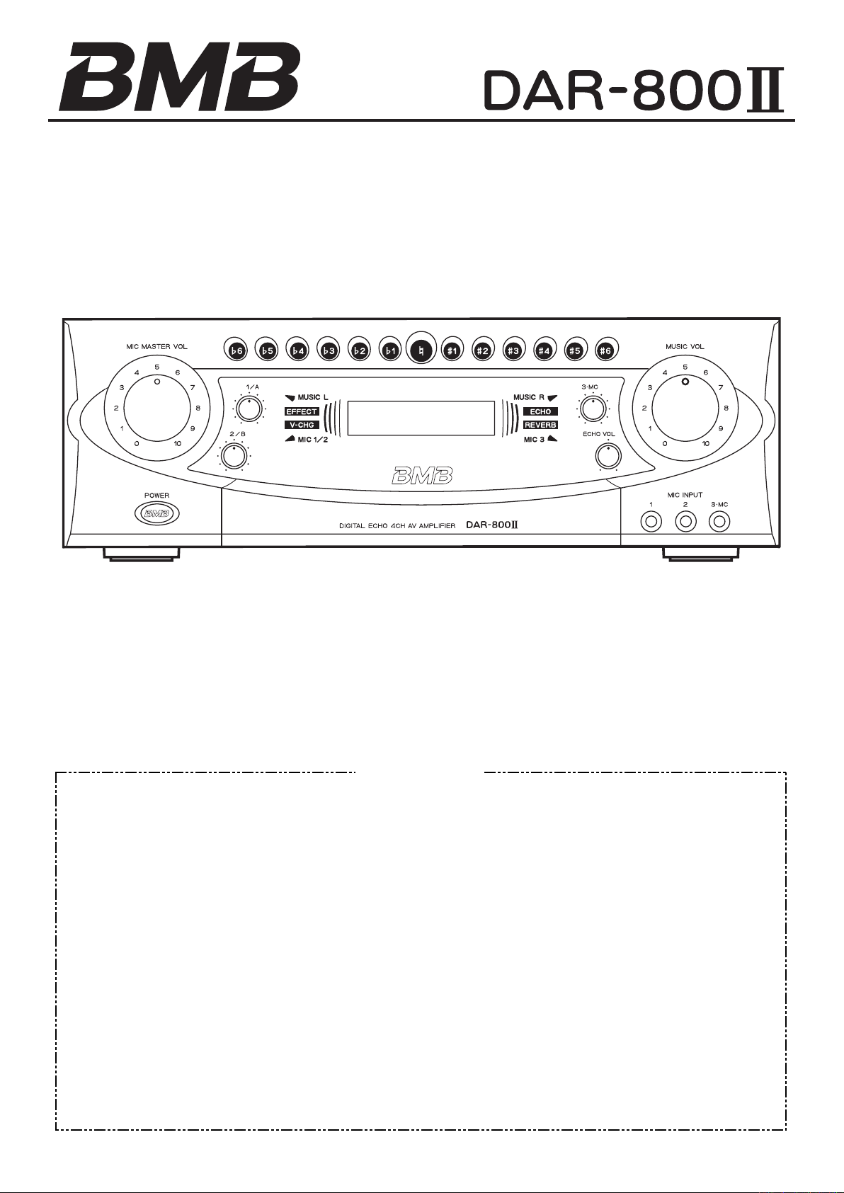
DIGITAL ECHO AV AMPLIFIER
OWNER’S MANUAL
Thank you very much for purchasing our DIGITAL ECHO 4CH AV
AMPLIFIER. Prior to use, be sure to read this owner's manual from
cover to cover so that you can make the most out of this unit. The
manual will come in handy whenever you come across any question or
trouble while using the unit.
IMPORTANT SAFETY PRECAUTIONS ................... 2
IMPORTANT SAFETY PRECAUTIONS
SPECIAL FEATURES
PRECAUTIONS FOR HANDLING
BEFORE CONNECTION
SAFETY PRECAUTIONS
NAMES OF FRONT-PANEL CONTROLS AND
THEIR FUNCTIONS................................... 6
NAMES OF REAR-PANEL CONTROLS AND
THEIR FUNCTIONS................................... 8
SYSTEM CONNECTIONS......................................11
CONNECTIONS
MECHANISM TO PREVENT EXCESSIVE VOLUME
LE VELS OF MIC MASTER VOL CONTROL AND
USIC VOL CONTROL ...................................... 13
M
.............................................. 4
......................................... 4
........................................ 5
................................................... 12
................... 3
........................... 4
DOOR LOCKING .................................................. 13
BASIC OPERATION
ECHO/EFFECT OPERATION
AUTO/VIDEO SIGNAL DETECTION MODE
VIDEO SWITCHING
REMOTE CONTROL OPERATION
TROUBLE SHOOTING
MAINTENANCE
AFTER-SALE SERVICING
MANNERS FOR CUSTOMERS
COPY RIGHT
ABOUT THE PRODUCT
SPECIFICATIONS ................................................ 21
..............................................14
................................ 15
..........16
.............................................. 16
........................ 17
......................................... 18
....................................................20
.................................... 20
.............................20
.......................................................20
....................................... 20
Page 2
2
IMPORTANT SAFETY PRECAUTIONS
CAUTION: TO REDUCE THE RISK OF ELE CTRIC SH OCK, DO NOT REMOVE
COVER (OR BACK). NO USER-SERVICEABLE PARTS INSIDE. REFER SERVICING
TO QUALIFIED SERVICE PERSONNEL.
The lightning flash with arrowhead symbol, within equilateral triangle, is intended to
alert the user to the presence of uninsulated “dangerous voltage” within the product’s
enclosure that may be of sufficient magnitude to constitute a risk of electric shock to
persons.
The exclamation point within an equilateral triangle is intended to alert the user to
the presence of important operating and maintenance (servicing) instructions in the
literature accompanying the appliance.
Thi s ap pli anc e has a ser ial n umb er
located on the rear panel. Please record
the model number and serial number and
retain them for your records.
Model number
Serial number
WARNING: TO PREVENT FIRE OR SHOCK
APPLIANCE TO RAIN OR MOISTURE.
For U.S.A.
TO THE USER
This equipment has been tested and found to comply
with the limits for a Class B digital device, pursuant to
Part 15 of the FCC Rules. These limits are designed
to p ro vid e rea son abl e pro tec tion again st ha rmf ul
interference in a residential installation. This equipment
generates, uses, and can radiate radio frequency energy
and, if not installed and used in accordance with the
instruction manual, may cause harmful interference to
radio communications.
However, there is no guarantee that interference will
not occur in a particular installation. If this equipment
does cause harmful interference to radio or television
reception, whic h can be determin ed by turning the
equipment off and on, the user is encouraged to try to
correct the interference by one or more of the following
measures.
a) Reorient or relocate the receiving antenna.
b) Increase the separation between the equipment and
receiver.
c) Connect the equipment into an outlet on a circuit
different from that to which the receiver is connected.
d) Consult t he dea ler or an e xperi en ced radio/ TV
technician for help.
HAZARD, DO NOT EXPOSE THIS
CAUTION
Cha nges o r mo dif i cat ions t o th is equip men t not
expressly approved by BMB Corp. for compliance could
void the user's authority to operate this equipment.
Page 3

IMPORTANT SAFETY PRECAUTIONS
1 Read these instructions.
2 Keep these instructions.
3 Heed all warnings.
4 Follow all instructions.
5 Do not use this apparatus near water.
6 Clean only with dry cloth.
7 Do not block any ventilation openings. Install in
accordance with the manufacturer's instructions.
8 Do not ins tall near a ny hea t sources such a s
radiators, heat registers, stoves, or other apparatus
(including amplifiers) that produce heat.
9 Do not defeat the safety purpose of the polarized
or grounding-type plug. A polarized plug has two
blades with one wider than the other. A grounding
type plug has two blades and a third grounding
prong. T he wid e blad e or the third pro ng are
provided for your safety. If the provided plug does
not fit into your outlet, consult an electrician for
replacement of the obsolete outlet.
• Do not expose this apparatus to drips or splashes.
• Do not place any objects filled with liquids, such as
vases, on the apparatus.
• Do not install this apparatus in a confined space
such as a book case or similar unit.
• The apparatus draws nominal non-operating power
from the AC outlet with its POWER switch in the off
position.
• The apparatus should be located close enough to
the AC outlet so that you can easily grasp the power
cord plug at any time.
• An app a r a t u s w i t h Class I constructio n shall
be connected to an AC outlet wit h a prote cti ve
grounding connection.
10
Protect the power c ord fro m bei ng w alked o n
or p inc hed p art icu lar ly at p lug s, con ven ien ce
receptacles, and the point where they exit from the
apparatus.
11
Only use attachments/accessories specified by the
manufacturer.
12
Use only with the cart, stand, tripod, bracket, or
table specified by the manufacturer, or sold with the
apparatus. When a cart is used, use caution when
moving the cart/apparatus combination to avoid
injury from tip-over.
13 Unplug this apparatus during lightning storms or
when unused for long periods of time.
14
Refer all servicing to qualified service personnel.
Servicing is required when the apparatus has been
damaged in any way, such as power-supply cord or
plug is damaged, liquid has been spilled or objects
have fallen into the apparatus, the apparatus has
been exposed to rain or moisture, does not operate
normally, or has been dropped.
3
Page 4

4
SPECIAL FEATURES
Ultra high performance digital power amplifiers (4CH).
•
3 ways of system configuration;
•
BTL: 360W + 360W (8Ø) stereo amplifier
SYSTEM 1+2 : Two sets of stereo speakers (4CH)
150W x 2 (8Ø) + 150W x 2 (8Ø)
SYSTEM 1 : One set of stereo speakers (2CH)
150W x 2 (8Ø)
Ultra Hi-speed DSP for multi effectors (8 effectors) and
•
feedback reducing function is also equipped.
Five input channel functions are automatically selected
•
in the preset priority sequence.
Easy-to-sing high-performance digital echo.
•
Effector terminal which permits connection of a graphic
•
equa lize r.
Five microphones can be used simultaneously, one of
•
which independently permits ON/OFF of echo for use
by an emcee (MC).
Low impedance compatible • power amplifier
configuration that can drive two pairs of speakers
individually.
A ±6-position key controller that can vary up to 3.0
•
pitch (chromatic intervals) is incorporated. At the end of
a tune, the standard pitch is resumed automatically.
A wireless remote control which permits remote control
•
of music volume, microphone volume, echo level, key
control, echo select and voice change.
Multi-function blue LCD-display indicates input position,
•
effectors, and massage.
The peak indicator of MIC 1/2, MIC 3 and MUSIC
•
L&R input indicates peak level to prevent overhead
saturation.
PRECAUTIONS FOR HANDLING
A place near window where rain may splash onto the
Avoid placing the unit in the following
·
places:
Where there is direct sunlight or near a heating body
•
such as a heater.
Where ventilation is poor so heat is trapped or there i
•
plenty of humidity or dust.
An unstable place which is subjected to vibrations or
•
inclination.
•
unit.
A place near cooking utensils where the unit may be
•
subjected to soot, smoke, fume or heat.
s
BEFORE CONNECTION
Cautions and warnings
·
When making connections, do so with the power to the
•
unit switched OFF.
As for the input a nd output jacks on the amplifier,
•
"white" denotes left channel whereas "red" right
channel. Firmly make connections in correct left and
right channels.
Connect cord plugs firmly. Improper connection may
•
lead to no sound output or to generation of noise.
When disconnecting the power cord from the outlet, be
•
sure to hold its plug.
Power consumption of the AC OUTLETS
·
See that the powe r consumption doe s not exceed
•
the wattage shown on the rear panel. Do not connect
any unit other than the system equipment to the AC
OUTLETS on the rear of this unit.
Do not connect a TV monitor as it may draw a large
•
current and its wattage may exceed the allowable
value when the power is switched ON, even if the
value indicated on the TV monitor is smaller than the
allowable wattage for this unit.
Page 5
SAFETY PRECAUTIONS
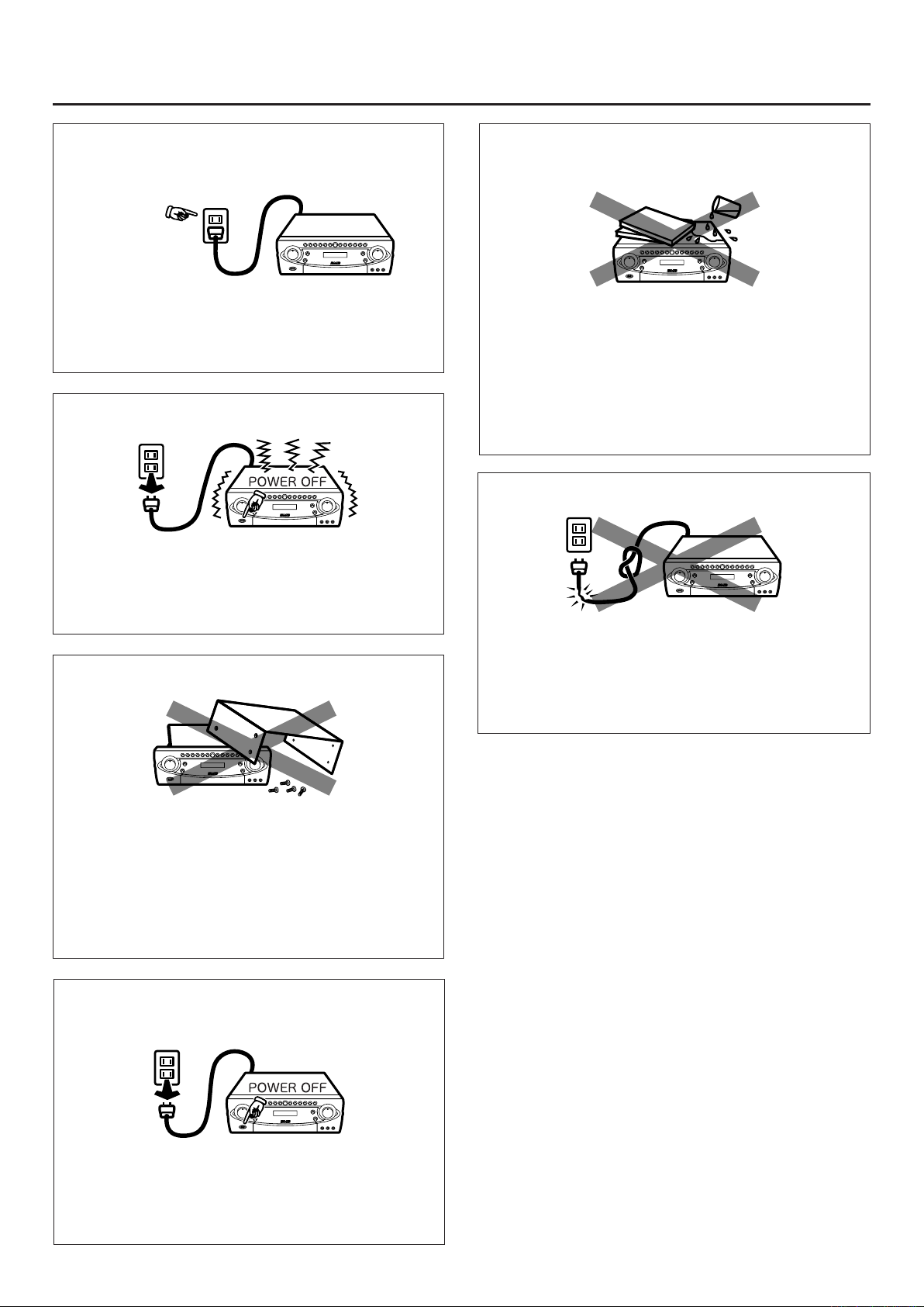
Check the voltage of your local mains
supply
Singapore: AC230V
Malaysia : AC240V
The power cord should not be connected to a direct
current (DC).
If malfunction occurs
If malfunction occurs, such as noise in the sound or
odor from the unit, remove the power cord from the
AC outlet and stop using the unit immediately and
consult your local dealer.
Do not disassemble the unit
Avoid push or drop any object or
liquid into the unit
Never push or drop any kind of objects into this unit
thro ugh openings as they m ay to uch dangerous
voltage points or short-circuit parts that could result
in a fire or electric shock. Never spill any kind of liquid
on this unit. If some object/liquid has been dropped,
remove the power cord from AC outlet and consult
your local dealer.
Do not damage the Power Cord
When remove the power cord from AC outlet, always
grasp and pull the plug, not the power cord. Damage
to the power cord may cause short-circuit or shock
hazard. Power cord should not be routed to under
furniture or where it may be likely damaged.
Do not attempt to modify, repair, or disassemble the
unit, as opening or removing covers may expose you
to dangerous voltage or other hazards. There are no
user serviceable parts inside. If the unit has a problem
or breakdown in case of you attempt to modify the
unit, quality of the unit can not be guaranteed.
When you leave your home or ins tallation
location
When you leave your home for a long period of time,
turn OFF the powe r and re move th e powe r co rd
from the AC outlet. This will prevent from unexpected
accident and fire.
5
Page 6
6
1
r
t
e
i
o
f
s
d
p
a
u
y
2
5
6
7
8
9
0
w
g
h
3
k
4
j
q
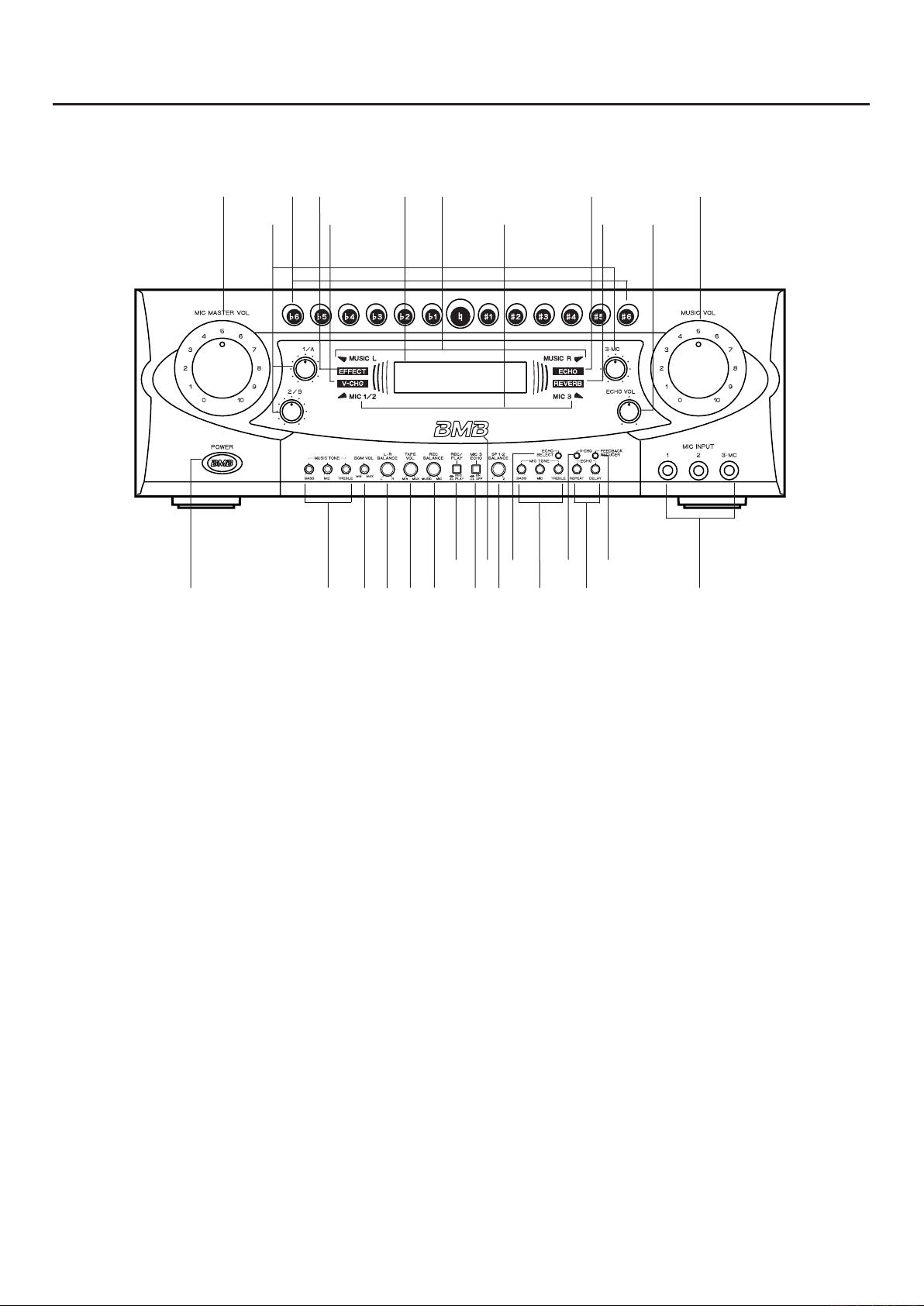
NAMES OF FRONT-PANEL CONTROLS AND THEIR
FUNCTIONS
FRONT PANEL
1POWER switch (ON ˘ /OFFÒ)
Press to turn ON the power. Press this again to turn it
OFF.
2MUSIC TONE controls
(BASS/MID/TREBLE)
Adjust the music input by boosting low, middle or high
frequency, respectively.
3 MIC TONE controls
(BASS/MID/TREBLE)
Adjust the microphone input by boosting low, middle or
high frequency, respectively.
4ECHO controls (REPEAT/DELAY)
REPEAT: Adjust the echo sustaining duration.
DELAY: Adjust the echo's repetition intervals.
5BGM VOL control
Adjust the BGM to an optimum level.
6L-R BALANCE control
Adjust the balance between the right and left channel
levels output from the speakers.
7TAPE VOL control
Adjust the "TAPE" playback volume level.
8REC BALANCE control
Adjust the balance between music source and
microphone sound during recording.
9REC/PLAY selector switch
(REC ˘ / PLAYÒ)
Press this switch to REC (˘) when recording sound
on a tape, and to PLAY (Ò) when playing a tape
(to prevent oscillation, be sure to set to REC when
recording sound).
.
03
MC/ECHO switch (ON ˘ /OFFÒ)
Press this switch to ON when effecting echo to the
third microphone (for use by an emcee) input.
q MIC INPUT jacks (1, 2, 3
Microphone input jacks.
wREMOTE control sensor
Receive the signal from the provided wireless remote
control unit (RMR-800).
.
MC)
Page 7
e KEY control buttons
Press the required button when changing the pitch of a
song. The buttons can vary the pitch in plus/minus six
steps with each button varying the pitch in chromatic
interval with respect to the standard pitch. The selected
pitch is indicated by the change in color of the pressed
button (when play of a song is over, the standard pitch
resumes automatically).
rMIC MASTER VOL control
Adjust the overall microphone input volume level.
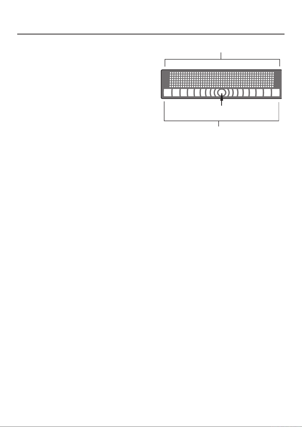
fLCD Display
1 Function indicator
Center Position
tMIC VOL controls (1/A, 2/B, 3
1 / A: Adjust the input levels of MIC INPUT 1 and MIC
A (on the rear panel).
2 / B: Adjust the input levels of MIC INPUT 2 and MIC
B (on the rear panel).
3.MC: Adjust the input level of MIC INPUT 3.MC.
In normal use, it is recommended to set the level to
…
maximum.
.
MC)
yMUSIC VOL control
Adjust the volume of the equipment connected to the
audio input terminals (This control does not change the
BGM volume. To change its volume level, use the BGM
VOL control).
u ECHO VOL control
Adjust the entire echo and effect level of MIC INPUTs 1,
2, 3.MC and MICs A and B (rear).
i EFFECT: Effect Mode Indicator
Indicator for any effector is selected.
2 Peak level indicator (Input level)
9 Dots x 2 (L&R)
1Function indicator
Indicate each function or situation as bellow:
Input position, Effectors, Feedback reducer, Voice
Change (V-CHG), and Error massage.
2Peak level indicators
Indicate input level of left and right channel (9 dots/
CH and Center dot).
gSP 1-2 BALANCE
Adjust the balance of output level between SYSTEM1
and SYSTEM2. Please refer to page 12 for more
information.
1. Speakers from SYSTEM1 (BTL mode: L CH)
2. Speakers from SYSTEM2 (BTL mode: R CH)
h ECHO SELECT switch
Press this switch to select preferable effectors, and the
selected efffectors will be indicated on LCD display.
o V- CHG: Vocal Change Indicator
Indicator as vocal change is selected.
pECHO: Echo Indicator
Indicator as echo is selected.
aREVERB: Reverb Indicator
Indicator as reverb is selected.
s MUSIC Input peak indicator
Indicate Input peak level of MUSIC (Left and Right).
dMIC Input peak indicator
Indicate peak input level of MIC-1/2/A (Left), MIC-3/B
(Right) (Peak position: -3dB)
Echo ∑REV ∑MIX ∑
jFEEDBACK REDUCER (ON/OFF)
Press this switch to reduce howling (feedback) by
searching howling point and filtering them.
CAUTION
If feedback reducer could not work sufficiently, check the
MIC, speaker's position and sound level by moving or
changing the position/angle of speaker unit, not to affect
feedback to the MIC.
:
kV-CHG selector switch
Press this switch when selecting Voice Change
effectors. Indicate LCD of selected Voice Change
effectors.
NOTE
For more information about i,o,p,a,s,d,h,j and
k, please refer to page 15.
7
:
Page 8
8
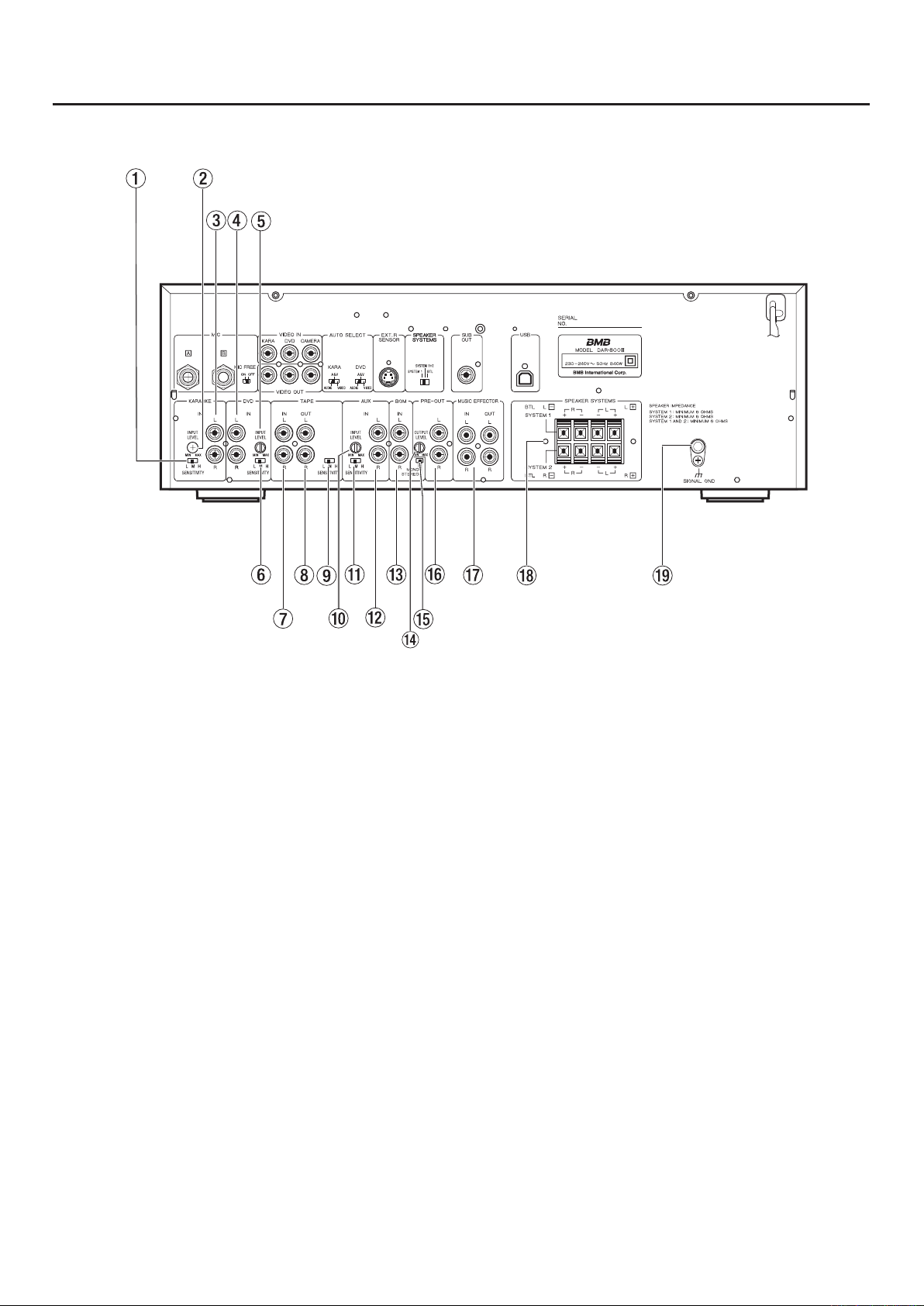
NAMES OF REAR-PANEL CONTROLS AND THEIR
FUNCTIONS
REAR PANEL
1KARAOKE SENSITIVITY switch
Set the sensitivity at which KARAOKE audio input level
is detected and switched automatically.
L(ow): Set to this position when the function does
not change to "BGM" or other mode even if
KARAOKE play is over.
M(id): Set to t his po s ition in no r m a l o p e ratin g
condition.
H(igh): Set to this position when the function changes
to other mode during KARAOKE play.
2 KARAOKE INPUT LEVEL control
Adjust this control by balancing with the level of other
inputs (DVD, TAPE, AUX).
3 KARAOKE audio input jacks
Connect the audio output jacks of KARAOKE player
here.
4DVD audio input jacks
Connect the audio output jacks of DVD/CD karaoke
player here (do not connect a BGV [background video]
DVD player here).
5 DVD INPUT LEVEL control
Adjust this control by balancing with the level of other
inputs (KARAOKE, TAPE, AUX).
6DVD SENSITIVITY switch
Set the sensitivity at which DVD audio input level is
detected and switched automatically.
L(ow): Set to this position when the function does not
change to "BGM" or other mode even if DVD
play is over.
M(id): Set to t his po s ition in no r m a l o p e ratin g
condition.
H(igh): Set to this position when the function changes
to other mode during DVD play.
7 TAPE audio intput jacks
Connect the audio output jacks of tape deck here.
8 TAPE audio output jacks
Connect the LINE IN jacks of tape deck here.
A level set by each input control other than the MIC
MASTER VOL control and MUSIC VOL control is output
here (this level has nothing to do with the speaker
volume level).
Page 9

9TAPE SENSITIVITY switch
Set the sensitivity at which tape playback input level is
detected and switched automatically.
rPRE-OUT output level control
Adjust this control by balancing with the level of power
amplifier.
L(ow): Set to this position when the function does not
change to "BGM" or other mode even if tape
play is over.
M(id): Set to t his po s ition i n no r m a l o p e ratin g
condition.
H(igh): Set to this position when the function changes
to other mode during tape play.
Note:
If there is much noise between prerecorded tunes
on the tape, the sensitivity may not be switched
automatically even if this switch is set to L. Conversely, if
the recording level is too low, the sensitivity may not be
switched automatically even if this switch is set to H.
0AUX INPUT LEVEL control
Adjust this control by balancing with the level of other
inputs (KARAOKE, DVD, TAPE).
qAUX SENSITIVITY switch
Set the sensitivity at which AUX audio input level is
detected and switched automatically.
L(ow): Set to this position when the function does not
change to "BGM" or other mode even if AUX
source play is over.
M(id): Set to t his po s ition i n no r m a l o p e ratin g
condition.
H(igh): Set to this position when the function changes
to other mode during AUX source play.
tMONO/STEREO select switch
Select the required position according to the audio
input from BGM (wired broadcasting system). If the
BGM is a stereo source, connect L and R channels
then set this switch to STEREO. If the BGM is a
monaural source, connect either L or R channel, then
set this switch to MONO.
yPRE-OUT output jacks
Output terminals for use in connecting a power
amplifier or mixer.
uMUSIC EFFECTOR IN/OUT jacks
Input and output jacks for use in connecting an
accessory unit such as a graphic equalizer.
Note:
Unless connection is proper, no sound will output.
iSPEAKER SYSTEMS connectors
Connectors to which 6Ø to 16Ø speakers are
connected. Please see page 12 for more information.
o SIGNAL GND terminal
It is recommended to ground the unit in order to
prevent this unit from electric shock or noise from
other equipment. If grounding is provided, trouble with
unknown cause may be remedied.
w AUX audio input jacks
Connect the audio output jacks of external audio
source equipment here.
e BGM audio input jacks
Connect the audio source such as BGM (background
music) from wired broadcasting system.
9
Page 10
10
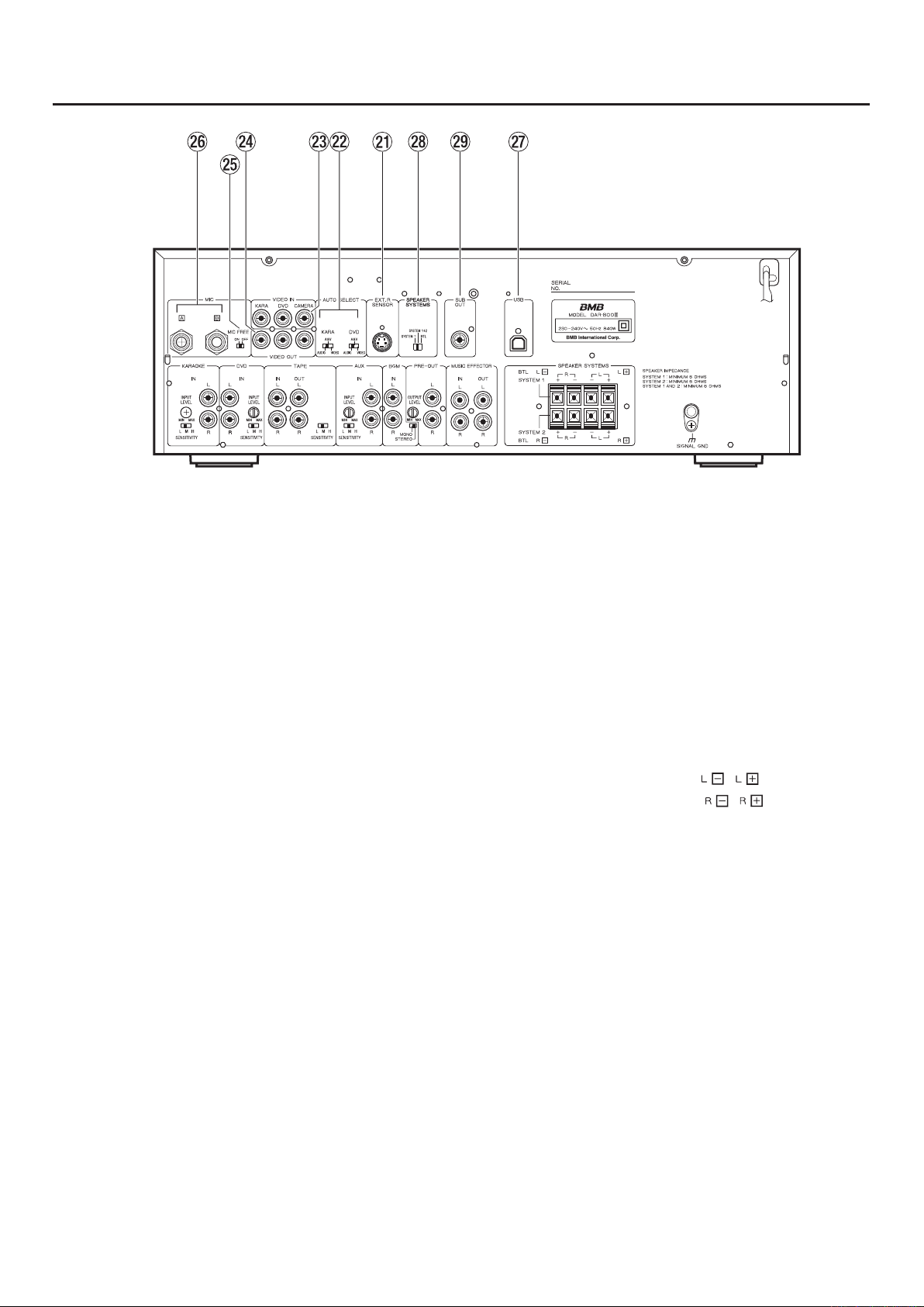
a EXT(ernal) REMOTE SENSOR terminal
/
/
Terminal to which an external remote control unit
is connected. If an external remote control unit is
connected, the remote sensor (infrared signal reception
window) on the front panel will be deactivated.
s AUTO SELECT switches
Depending on the switch position, the detection mode
will be switched from among the three modes, AUDIO,
A & V or VIDEO (see page 17).
d VIDEO input jacks
KARAOKE: Connect the video output jack of karaoke
unit here.
DVD : Connect the video output jack of DVD
karaoke unit here.
CAMERA : Connect the video output jack of video
cam era her e. The v ideo s igna l inpu t
to this jack appears on the TV monitor
when the function is set to BGM (wired
broadcasting system), TAPE or AUX.
fVIDEO output jacks
Up to three TV monitors can be connected to these
video output jacks.
Note that the emcee microphone (3.MC) can be used
at all times.
gMIC FREE switch
Flipping this switch to ON allows the microphone to be
used at all times. When the function is set to BGM (wired
broadcasting system), this switch allows microphone
sound to be turned ON or OFF. If this switch is set to
OFF, no sound is output in the BGM mode.
hMIC [A][B] jacks
Jack A is a mixing input jack with MIC INPUT 1 on the
front panel whereas jack B is a mixing input jack with
MIC INPUT 2.
jUSB I/F (Interface)
Connect USB cable for maintenance purpose.
Not for normal use.
k BTL Selector switch
BTL: Both speakers are driven by BTL AMP.
SYSTEM 1 = L-Channel
SYSTEM 2 = R-Channel
SYSTEM1+2:
Each speaker system is driven individually (4
separate amplifiers).
SYSTEM 1 = L-R (Stereo)
SYSTEM 2 = L-R (Stereo)
SYSTEM1:
One pair of speaker is available (factory preset).
Please see page 12 for detailed example of speaker
terminal setting.
lSUB OUT
Connect the jack of the amplifier of Sub woofer for
driving super low frequency (super low frequency =
under 50Hz).
Page 11
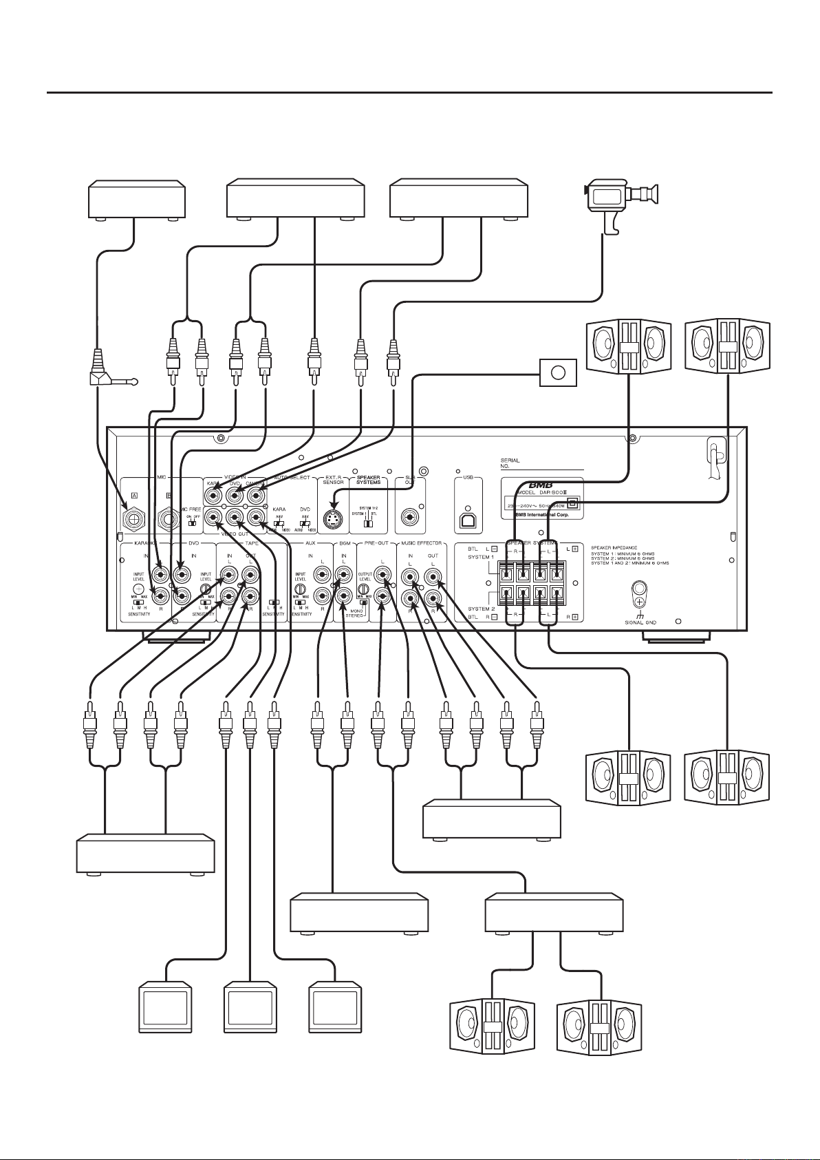
SYSTEM CONNECTIONAS
Infrared wireless
Microphone receiver
(option)
WT-4500
Karaoke player
DVD player
Video camera
Remote sensor
Right
Left
Cassette deck
TV monitor
BGM player
2 31
TV monitor TV monitor
11
Graphic equalizer
Right
Left
Right
Power amplifier
Left
Page 12
12
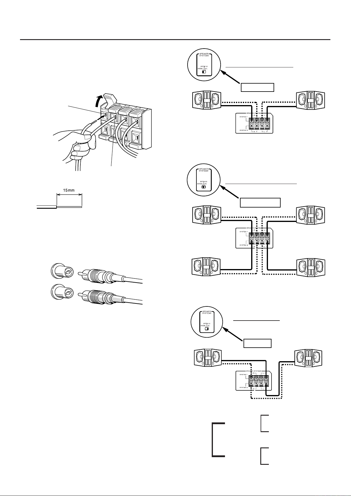
SYSTEM 1
SYSTEM 1+2
BTL(L:-)
BTL(R:-)
BTL(L:+)
BTL(R:+)
BTL
CONNECTIONS
How to connect speaker cords
·
1. Press the lever, then insert the stripped end of the
cord.
2. Release the lever so that the wire is held securely.
Match ± wire with
± connector.
Match — wire with — connector.
Strip about 15 mm of the outer
covering from the ends of the cords
by using the pliers before making
connections.
When connecting RCA pin plug cords, match the
•
colors. Connect red cord to red jack and white to
white.
One pair of speakers
150W
MIN.6Ø
NOTE : Never connec t sp eaker s to th e termina l 2,
since it is not active and causes no sound as
SYSTEM 1 set ting.
Two pairs of speakers
150W
MIN.6Ø
150W
MIN.6Ø
150W
MIN.6Ø
Left
Right
Cautions:
See tha
•
sticking out of the speaker connectors. If the wire frays
come into contact with other conductors, it may lead to
failure of the unit.
Use speakers with a nominal impedance of
•
If speakers
•
connected, the protective circuit may go into operation,
defeating normal stereo playback.
When BTL setting is on, use speakers with a nominal
•
impedance of 8Ø or more.
t wire frays (straggly conductors) are not
White
Red
with an impedance lower than 6Ø are
White
Red
6Ø to 16Ø.
150W
MIN.6Ø
150W
MIN.6Ø
For BTL mode
LCH 360W
(SP Input>360W)
MIN.8Ø
SYSTEM 1 Min. 6Ø
STEREO Min. 6Ø
SYSTEM 2 Min. 6Ø
RCH 360W
(SP Input>360W)
MIN.8Ø
(L - CH) 150W
(R - CH) 150W
(L - CH) 150W
(R - CH) 150W
Min. 6Ø
Page 13
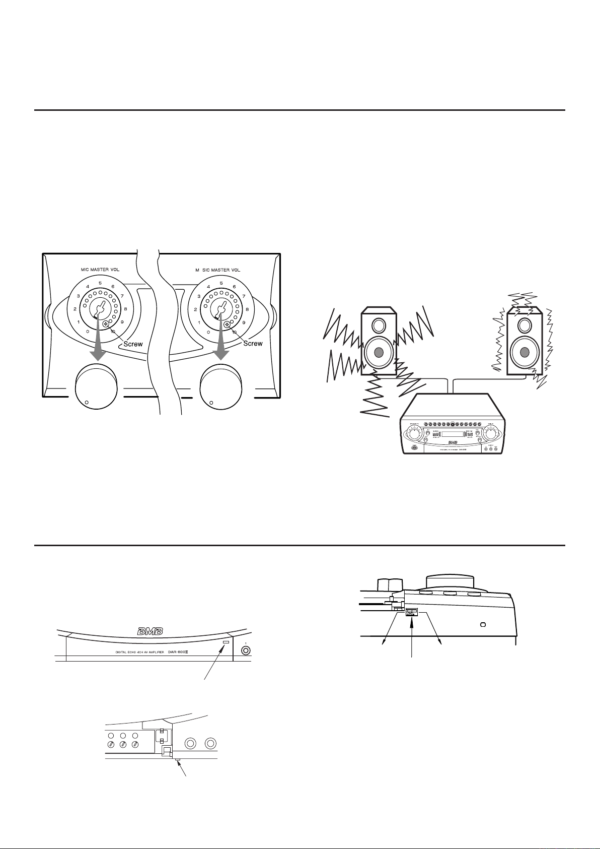
MECHANISM TO PREVENT EXCESSIVE VOLUME
U
Push near the marking of door to open/close.
Door lock lever
Slide the lever for door open/close
OPEN position
LOCK position
LEVELS OF MIC MASTER VOL CONTROL AND
MUSIC VOL CONTROL
Although usually the volume level can be varied from level
0 to a maximum level of 10, this feature allows you to
change the maximum volume level to the required setting
(such as up to 7, 8, 9, etc.).
Setting procedure
·
1. Remove the volume knob.
2. Remove the screw behind the knob, then reinstall it to
the required maximum level.
CAUTION:
Please connect higher power handling speakers when
you use this amplifier DAR-800II.
Th e maximum power of DAR-80 0II is over 36 0W/CH
peak.
Please adjust each volume to obtain proper sound level
by confirming the Input peak indicator and the Peak level
indicators to prevent over load level and distor tion. It
should be avoided handling the highest power and over
distortion since it would cause the trouble of the system.
Never listen the sound near the speakers because the
high sound pressure level will lead to ear problems.
The MIC MASTER VOL control knob and MUSIC VOL
control knob cannot turn more than the position where
the screw fixed.
Please set the maximum volume level to prevent over
leveled driven and to protect speakers.
DOOR LOCKING
The front door is available to lock from door opening for
holding each setting adjust.
To relea se the door loc k, slide the lock l ever on the
bottom of the front panel.
From the bottom view :
OPEN position : It is possible to open the front door by
pushing right side of the door.
LOCK position : The front doo r is loc ked and unable
to open the door. Loc k the d oor for
preventing tinker around setting.
CAUTION :
Never close the door when the door stopper is on
LOCK position, as it would cause the door broken.
13
Page 14
14
6
1
4
5 2
3
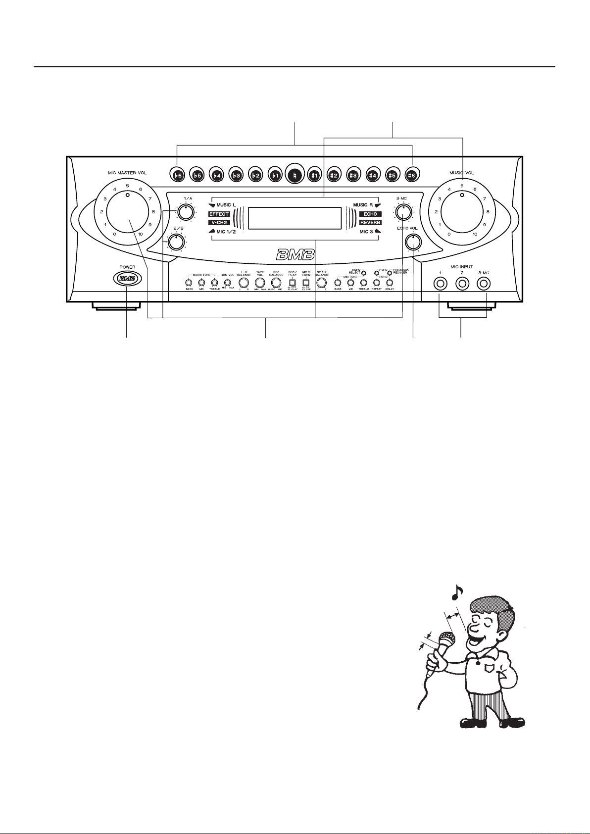
BASIC OPERATION
1Depress the power switch (˘) of this unit and other
equipment.
2 Connect the required number of microphones.
3Set the karaoke music machine to the play mode, then
set the MUSIC VOL control to the required level, by
checking the Peak level indicator of music input level.
4Turn the MIC VOL controls and MIC MASTER VOL
control to balance the level with that of music source,
by checking the Peak level indicator of mic input level
(MIC 1/A, 2/B, 3
Notes: 3and 4
If the peak level indicator blinks with red, input level is too
high, then reduce the input level by adjusting MUSIC VOL,
or MIC MASTER VOL controls.
.
MC).
5 Adjust the echo level as required.
6 Adjust the pitch using the key control buttons.
Now that the required setting is over, you do not have
to operate this unit. All you need to do is to operate the
music source equipment.
How to use microphones properly and
·
operating precautions
Keep the microphone approx. 5 to 10 cm away from
•
your mouth.
To make the voice sound clearly, leave the proper
•
space between the microphone head and holding
position on the microphone.
Do not cover the lower wind screen of the microphone.
•
As this may muffle the bass sound, defeating proper
vocal reproduction. It may also cause howling.
When you use the IR microphone system, do not cover
•
or shade the IR radiation parts (black plastic window)
of microphone at the bottom as the wireless signal is
weakened.
Provide a space of
approx. 5 to 10 cm.
Leave the proper space.
Do not use the microphone toward the speaker as it
•
may cause the feedback (howling).
Page 15
1
2
3
4
5
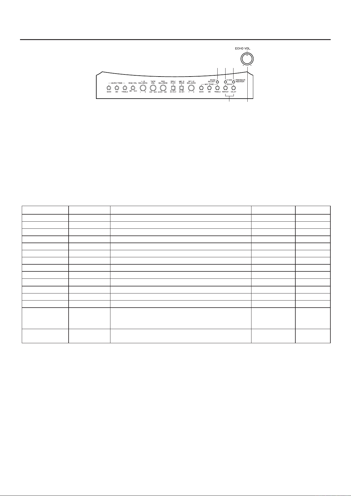
ECHO/EFFECT OPERATIONS
Using Echo effectors
1. Select ECHO mode by pushing 1 ECHO SELECT
switch until ECHO Indicator is lit.
2. Adjust ECHO level of microphones to background
3. Adjust ECHO speed, and delay by turning 3ECHO
Controls.
music by 2 ECHO VOL Control.
1ECHO SELECT
Push this switch when selecting effectors including
ECHO. The selected echo mode is indicated on LCD
display, and it can change the following order;
ECHO ∑ REV ∑ MIX ∑ ROCK
LED indicates "ECHO", "REVERB", "EFFECT".
∑
Effectors
Name LCD FUNCTIONS PARAMETER V-CHANGE
ECHO ECHO ECHO Level, ECHO Rep, ECHO Delay 0~50 X
REVERB REVERB REV REP, REVERB Level 0~50 X
MIX MIX Mix Echo and reverb 0~50 X
ROCK ROCK Rock sound effect level controllable
ENKA ENKA Japanese Enka sound effect level controllable
BALLAD BALLAD Ballad sound effect level controllable
FLANGER FLANGER Flanger effect level controllable
PAN NING PAN NING Pans sound left and right
DISTORTION DISTORTION Distortion sound effect level controllable
RADIO VOICE RADIO Radio voice sound effect level controllable
DUET DUET Duet sound effect level controllable
EFFECT OFF EFFECT OFF
VOICE CHANGE
(V-CHG)
FEEDBACK
REDUCER
V-CHG OFF
V-CHG UP
V-CHG DWN
FB-RED ON
FB-RED OFF
Voice change is not available
Voice change as hi-voice (1 octave up=Female voice)
Voice change lo-voice (1 octave down=Male voice)
Feedback reducer is activated.
Feedback reducer is stopped.
0~50
0~50
0~50
0~50
0~50
0~50
0~50
-17~+17
¨
¨
¨
¨
¨
¨
¨
¨
2ECHO VOL Control
For adjusting the entire echo and effect level of
microphones 1/A, 2/B and 3.MC. Turn clockwise to
increase it.
3 ECHO Controls (REPEAT/DELAY)
REPEAT: Adjust the echo sustaining duration.
DELAY: Adjust the echo's repetition intervals.
4FEEDBACK REDUCER
Push FEEDBACK REDUCER switch to prevent
feedback (peaking of speakers feedback).
LCD indicates as “FEEDBACK ON” when the effect is
working (Please see j on page 7 for CAUTION).
5V-CHG selector switch
Vocal change function is available and V-CHG Indicator
is lit when some effectors are selected.
Please see the table above. "¨" is available and "X" is
not available.
V-CHG UP : Change the voice to high key's tone (like
Female voice).
V-CHG DWN: Change the voice to low key tone (like
Male voice).
15
Page 16
16
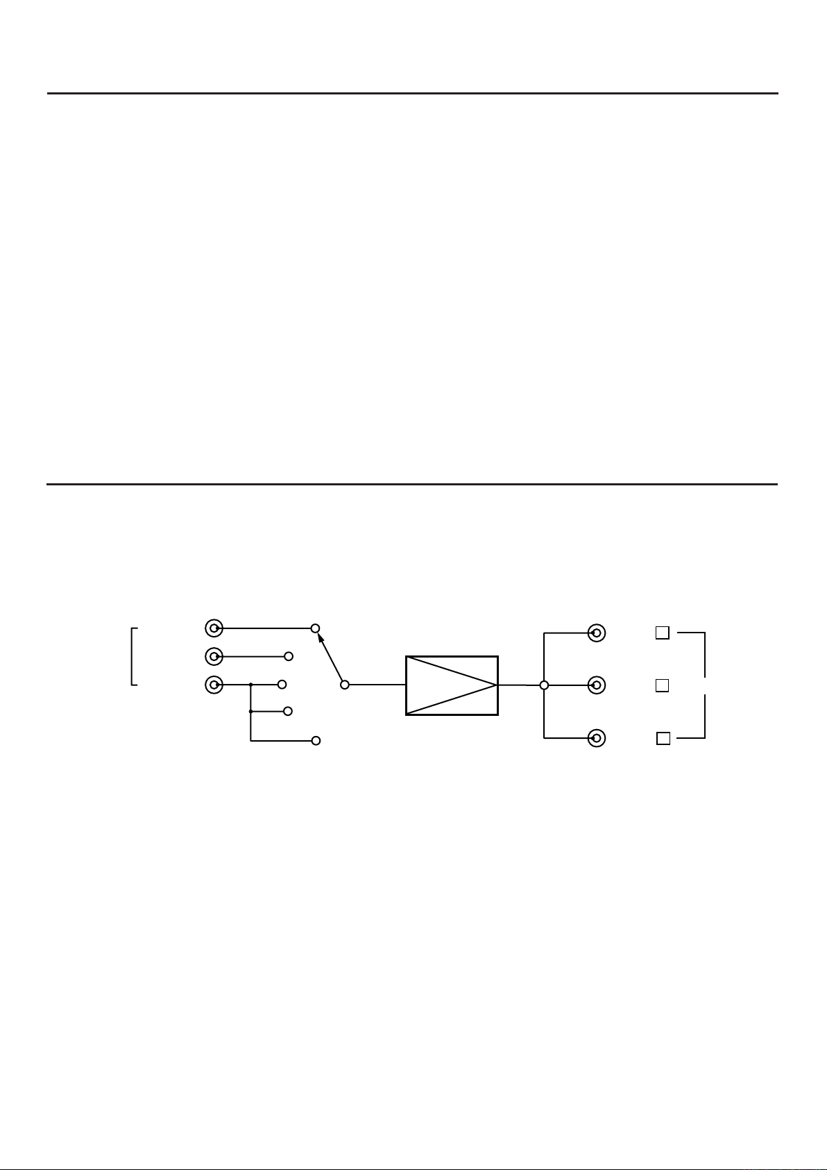
AUDIO/VIDEO SIGNAL DETECTION MODE
Monitor 1
Monitor 2
Monitor 3
KARAOKE
KARAOKE
DVD
DVD
AUX
TAPE
BGM
CAMERA
VIDEO IN
VIDEO OUT
As for the KARAOKE and DVD functions, the detection
mode will be sw itched from among the three mode s
(AUDIO, A & V or VIDEO) depending on the position of the
AUTO SELECT switches on the rear panel. The AUX and
TAPE functions should be detected by the audio signal.
‚ When the switch is set to "AUDIO"
The audio input is detected, and the function will
change in the following priority preset sequence:
1K ARAOKE, 2DVD, 3AUX, 4TAPE, and 5BGM.
For example, if there is no KARAOKE audio, and DVD
and AUX are being played, priority will be given to the
DVD audio, and DVD input is played.
VIDEO SWITCHING
Although video signal is switched simultaneously with the
switching of the audio signal, if the function is set to AUX,
TAPE or BGM, the video signal input to the video camera
will be output.
‚ When the switch is set to "VIDEO"
The video input is detected, and the fun ction will
change in the following sequence:
1KARAOKE, 2DVD, and 3Video camera.
‚
When the switch is set to "A & V"
Either the audio input or video input is detected, and
the function will change in the priority sequence.
The audio will cha nge in t he f ollow ing sequenc e:
1KARAOKE, 2DVD, 3AUX, 4TAPE, and 5BGM.
The v ide o will chan ge i n the fol low ing sequenc e:
1KARAOKE, 2DVD, and 3Video camera.
If both audio and video are input, the function will be
switched by the signal detected first.
Page 17
1
2
3
4
5
6
7m
REMOTE CONTROL OPERATION
5ECHO SEL (select) button
While holding down the button, the programed effector
is selected.
At this time, the selected effect is indicated to the LCD
display.
Please see detailed information on page 15.
6V-CHG select button
While holding down the button, the vocal change
function is available.
At this time, “V-CHG” function is indicated to the LCD
in the following order.
V-CHG OFF ∑ V-CHG UP ∑ V-CHG DOWN ∑
V-CHG OFF ∑
Please see detailed information page 15.
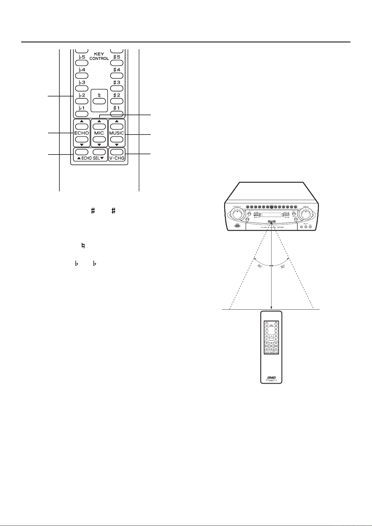
1KEY control buttons
‚ To increase pitch ( 1 to 6) : This button can
increase up to 3.0 pitches in six steps with a press of
each button varying pitch in chromatic interval
respect to the standard pitch.
‚ Standard button ( ) : Pressing this button allows the
standard pitch to be resumed.
‚ To lower pitch ( 1 to 6) : This button can decrease
up to 3.0 pitches in six steps with a press of each
button varying pitch in chromatic interval with respect
to the standard pitch.
Note :
When play of a tune is over, the standard pitch resumes
automatically.
with
2 ECHO control button
While holding down the button, the echo level will either
increase or decrease depending on which side of the
button is pressed.
3MIC MASTER control button
While holding down the button, the volume level will
either increase or decrease depending on which
side of the button is pressed. At this time, the LED in
the control knob on the front panel will flicker. Fineadjustment of volume is possible by gently pressing the
button.
4 MUSIC control button
While holding down the button, the volume level will
either increase or decrease depending on which
side of the button is pressed. At this time, the LED in
the control knob on the front panel will flicker. Fineadjustment of volume is possible by gently pressing the
button.
ª Wireless remote control
The allowable distance between the wireless remote
control unit (RMR-800) and the remote sensor (infrared
signal reception window) is approx. 7 m. Note that the
remote control may not work if it is not properly pointed
toward the re mote sensor or if there is any obstacle
between the remote control and the sensor.
17
Page 18
18
1
2
3
REMOTE CONTROL OPERATION
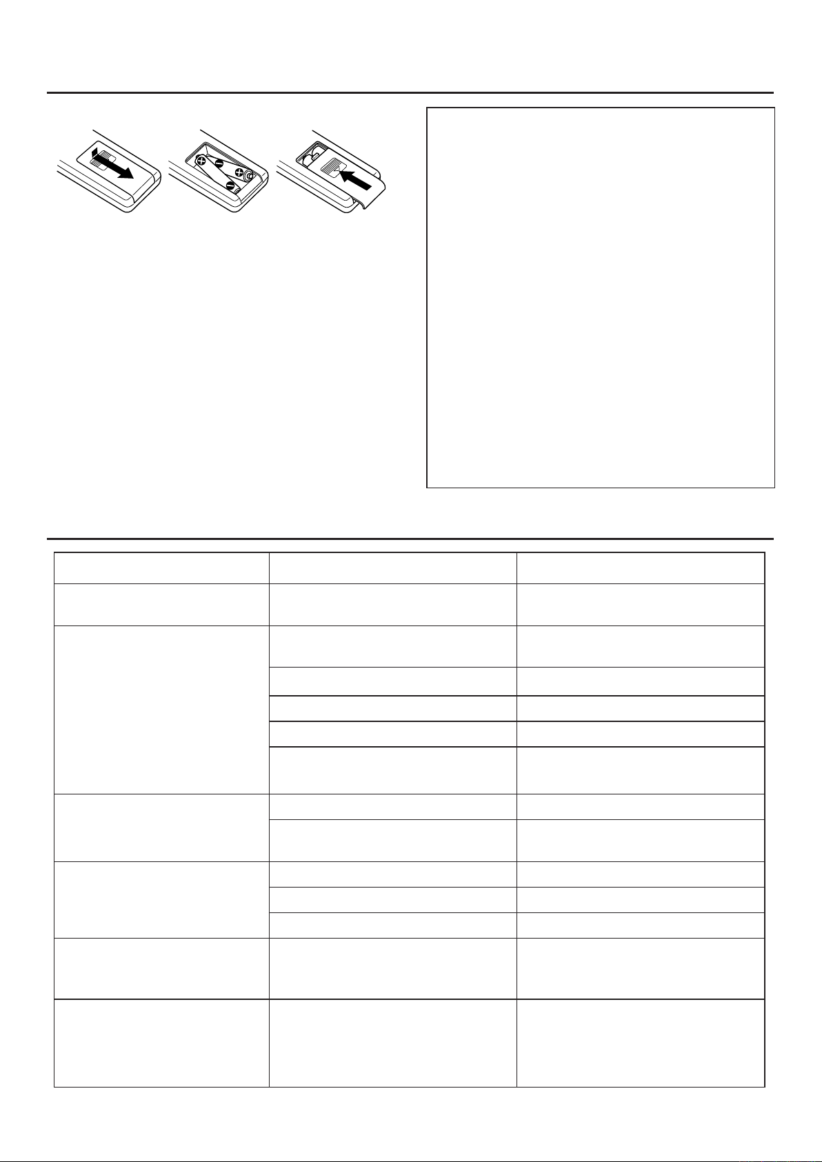
Changing the batteries
1Slide open the lid on the back side in the direction of
the arrow.
2Insert two dry batteries (AAA,UM-4) as shown in
above diagram.
3Close the lid in the direction of the arrow.
ATTENTION
The improper use of batteries may lead to chemical
leakage or explosion.
Observe the following precautions:
1Insert batteries with their positive (+) and negative
(-) poles positioned correctly according to the
indication on the battery compartment.
2 Do not use an old and new batteries together.
3 Use batteries of the same type. Never use
batteries of different types together as voltage
may be different, even if they are the same shape.
4 Discard exhausted batteries into a designated bin
(so as not to contaminate the environment).
5 When you feel op erati n g di s tance become
shorter, the battery is exhausted. Replace with
new batteries.
TROUBLESHOOTING
Trouble Possible cause Remedy
No power is supplied to the unit. The power plug is disconnected from
Power ON but no sound. Music Volume control or Mic Volume
No sound at beginning of the
music when switching function.
No sound from microphone (but
music is played back).
‚
the power outlet.
‚
control may be set to minimum.
The speaker cables are disconnected. ‚Connect the speaker cables properly.
Break in the speaker cables.
‚
Speaker cables are short - circuited.
‚
Equipment to be connected are dis-
‚
connected.
Sensitivity switch is set to "low".
‚
Output level of audio component is set
‚
to minimum.
Microphone switch is set to OFF.
‚
Break in the microphone cord.
‚
The microphone plug is disconnected. ‚Connect it properly.
Firmly connect the power plug to the
‚
power outlet.
Adjust for the proper sound level.
‚
‚
Repair the break in the cables.
‚
Repair the short - circuit.
‚
Properly connect the equipment.
‚
Set the Sensitivity switch to "high".
‚
Adjust it for suitable level if it has a
‚
level control.
Set it to ON.
‚
Repair or replace it.
‚
‚
No sound from microphone only
when function is set to BGM.
No music sound (BGM and
microphone sounds are available).
The MIC FREE switch is set to OFF.
‚
No external unit with music effector
‚
jacks is connected.
If it is set to OFF, no sound is output
‚
from microphones 1/2/A/B when the
function is set to BGM.
Connect external unit to the MUSIC
‚
EFFECTOR jacks properly. If the unit
connected to the IN jacks yet it is not
connected to the OUT jacks, music
sound is not output.
Page 19

TROUBLESHOOTING
Trouble Possible cause Remedy
No video. VIDEO OUT jacks are not fully con-
Function is switched to AUX, TAPE
or BGM while playing KARAOKE
or DVD.
No audio is played back even if
KARAOKE or DVD audio signal is
input.
Playback picture does not appear
even if KARAOKE or DVD signal is
input.
No sound : Amplifier stops as error “ERROR 01” is indicated on LCD
No sound : Amplifier stops as error “ERROR 02” is indicated on LCD
No sound : Amplifier stops as error “ERROR 12” is indicated on LCD
‚
nected.
VIDEO IN jacks (KARAOKE, DVD,
‚
CAMERA) are not fully connected.
Input sensitivity of KARAOKE or DVD
‚
is low.
AUTO SELECT switches are set to
‚
VIDEO.
AUTO SELECT switches are set to
‚
AUDIO.
‚
‚
‚
Firmly insert TV monitor plug into
‚
VIDEO OUT jack.
Firmly insert plugs into VIDEO IN jacks.
‚
Set SENSITIVITY switch on the rear
‚
panel to H.
Set AUTO SELECT switches to AUDIO
‚
or A & V.
Set AUTO SELECT switches to VIDEO
‚
or A & V.
Power amplifier of SYSTEM-1 is error.
‚
Please see information as bellow.
Power amplifier of SYSTEM-2 is error.
‚
Please see information as bellow.
Power amplifier of SYSTEM-1 and -2
‚
is error. Please see information as bellow.
If an "ERROR" indication appears and no audio is output
while using the unit, switch the power OFF, then check the
following:
1 Is the impedance of the connected speakers proper?
See page 12 for more details.
2 Isn't the amp temperature too high while using it?
If it is, leave the unit for approx. 20 minutes, then use it
with the volume lowered.
Check the left, then switch the power ON.
At this time, see that the "ERROR" indication does not
appear. If it still does, the unit is faulty; contact the dealer
from whom you purchased it.
19
Page 20
20
MAINTENANCE
When the unit gets dirty, wipe with a soft dry cloth.
If the unit is extremely dirty, soak a soft cloth in a diluted
solution of dish-washing detergent (four - five parts of
water to one part of detergent), wring the cloth, wipe the
dirt away, then wipe the unit with a dry cloth. Never use
alcohol, thinner, benzine, insecticide, or other
AFTER-SALE SERVICING
1If this unit is found to be defective, your local dealer will
repair or replace defective parts with charge at your
request.
2Before you request the repair to your local dealer, see
the "TROUBLESHOOTING" section and check it again.
volatile agents, for they may damage the surface coating
or deprive the luster from the unit. Also, do not wipe the
unit with a chemical-impregnated cloth or leave it on the
unit for a long period of time, for this may degrade the
surface finish or strip off the coating.
For dealer :
If yo u a re requ este d the af ter-sale service from your
customer, check the following contents first.
Confirming the details of the accident.
•
Checking out all cables and connections.
•
Caution of operation and instruction for using the
•
system to your customer.
If the unit is found to be defective and it is difficult to
re pair, bring the defective unit to your n eares t BMB
authorized service center.
MANNERS FOR CUSTOMERS
Karaoke, though enjoyable, could be noisy at times unless
proper time and place are chosen. Please be sufficiently
thoughtful of your neighbors.
Karaoke volume could be high if you are engrossed in
singing.
Even a sma ll sound can be pe netrating especially at
quiet night. Therefore, please give special attention to
audio level especia ll y at night. As no sound leaks to
your neighbors, it is advisable to close the wind ows
and observe proper manners to maintain pleasant living
environment.
COPYRIGHT
Broadcasting, music source such as recorded music
•
ta pe, DVD, v ide o tap e, CD a nd so on are strictly
protected under copyright law.
You need to have permission from the copyright
•
hol
commercial use, or sell dubbed media to other people
except when enjoying these sources by yourself.
der to use, distribute, rent these music sources for
ABOUT THE PRODUCT
This unit is p r oduced by ha r mless m ater i a l s i n
•
conformity with relevant product safety laws.
Page 21
SPECIFICATIONS
Amplifier
Audio output power:
150W + 150W + 150W + 150W (Separate 4 amps)
360W + 360W (BTL)
Total harmonic distortion (1 kHz, -3 dB, 8Ø)
Audio input (sensitivity/impedance)
.......................................................6 mV/3.3 kØ
MIC
KARAOKE, DVD, TAPE, AUX
BGM (wired)
Audio output (level/impedance)
PRE-OUT
MUSIC EFFECTOR
Recording output
SUB OUT
Frequency response
...................................... 20 Hz to 20 kHz ±3 dB
MIC
MUSIC
Tone control response
Music tone bass
Middle
Treble
Mic tone bass
Middle
Treble
Speaker impedance
Key control range ...........................13 steps ± 3.0 pitch
Video input
(sensitivity/input impedance)
Video output
(output level/output impedance)
.......................................300 mV/22 kØ
.................................................2.5 V/1 kØ
...............................300 mV/1 kØ
.................................300 mV/1 kØ
.................................................2.5 V/1 kØ
..................................10 Hz to 20 kHz ±3 dB
............................. ..± 7 dB (100 Hz)
....................................... ....± 5 dB (2 kHz)
........................................ ..± 7 dB (10 kHz)
................................. ± 10 dB (100 Hz)
....................................... ....± 5 dB (2 kHz)
........................................ .±10 dB (10 kHz)
...................................... 6Ø to 16Ø
..............300 mV/22 kØ
(one channel only, 1 or 2)
................... 1 Vp-p/75Ø
.............1 Vp-p/75Ø
.............0 .1%
Power Supply / Others
<Singapore / Malaysia version>
Power supply
Power consumption
................. AC230V/50 Hz (Singapore)
AC240V/50 Hz (Malaysia)
....................................... 840 W
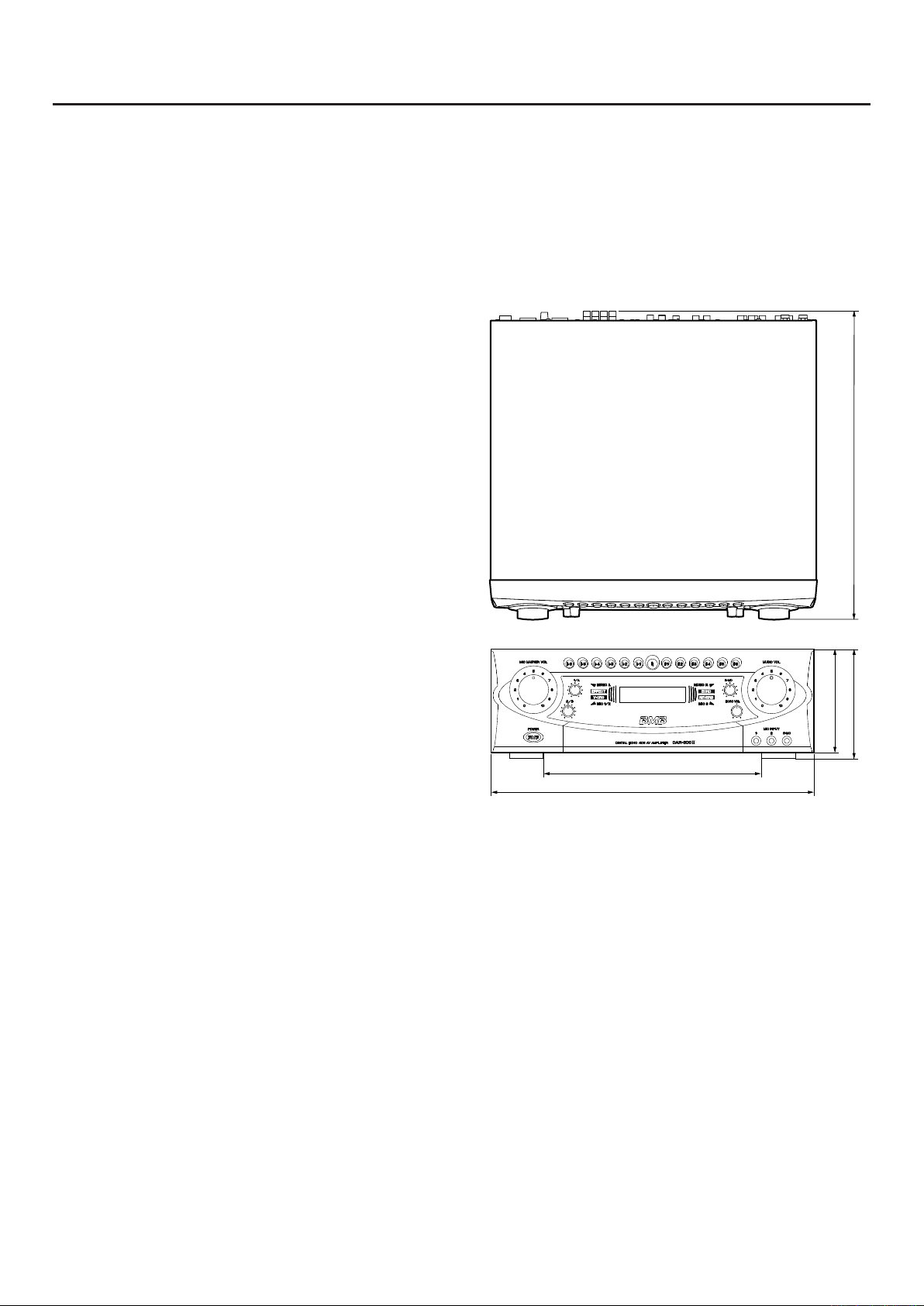
Dimensions (W x H x D) ................. 420 x 142 x 396 mm
Weight
Accessories
•
.................................................................17.1 kg
Owner's manual
Wireless remote control unit (RMR-800)
AAA (UM-4) batteries
Design and specifications subject to change without
notice.
..................................................... 1
................. 1
............................................. 2
133mm
316mm
420mm
396mm
142mm
21
Page 22

BMB International Corp.
http://www.bmb.com
 Loading...