

Page 1

Installation Instructions
Console Megashifter
1982-1992 Camaro and Firebird*
Part Number 80692
© 2010, 2007, 2006, 2001, & 2000 by B&M Racing and Performance Products
This B&M Megashifter is designed to fit
in the consoles of 1982-1992 Chevrolet
Camaros and Pontiac Firebirds*. In 1982 these
vehicles were equipped with three speed
automatic transmissions. Since 1983 they
have been equipped with four speed automatic transmissions. Shifter #80692 is for
three speed automatic and four speed automatic transmissions. The shifters are equipped
with neutral start and backup light switches
and a five foot shift cable. If the shifter is used
with the four speed automatic transmission
(TH-700-R4,4L60, 4L60E, or 4L65E), the
blocker pin and E-clips shown in Figures #2
and #3 must be removed.
To install this shifter on a 4L60E or 4L65E
equipped with a PRNDL switch you will need
B&M installation kit #75498, otherwise use
supplied GM bracket.
Please read the instructions and review
the illustrations thoroughly before beginning
the installation.
The mechanical components of this shifter
are precision made and assembled at our
factory. Any modification or disassembly of
these parts can cause the shifter to malfunction and will void the warranty. You should
disassemble only those items outlined in the
instructions.
The vehicle should be about 2 feet off the
ground for ease of installation. Use jack
stands, wheel ramps or a vehicle lift. Make
sure the vehicle is firmly supported before
attempting to work on it.
INSTALLATION
STEP 1. Remove the knob from the stock
shifter. Pull firmly up on the detent button and
it will pop out. Remove the snap ring inside of
the knob and pull off the knob.
STEP 2. Remove the top cover of the console. On the Camaro remove six screws
(some of the screw heads on the cover plate
may be dummy screws) and on the Firebird
remove four exterior screws and one in the
Printed in U.S.A.
ashtray. Remove the console light from the
cover.
STEP 3. Disconnect the two cables from
the shifter. The left hand cable is the shift
cable and the right hand cable is the Park lock
cable. Remove the wiring plug from the shifter
body. Unbolt and remove the shifter mechanism (See Figure #1). Remove the cable
bracket and the selector lever from the transmission (See Figure #4). Remove the shift
cable from the vehicle.
STEP 4. The Park lock cable must be wired
in the Park position (fully in) so that the
steering column lock will work and will allow
the key to be removed. The cable should also
be secured inside of the console out of the
way. After wiring the cable in this position
check to see that the steering column lock
works correctly, and that you can remove the
key. WARNING: With the interlock dis-
abled in this manner it is possible to
lock the steering column at any time, so
be careful not to turn the key to the
“LOCK” position while the car is moving.
STEP 5. Assemble the neutral safety and
reverse light switches to the bracket using
two #4-40 x 1" screws and nuts, as shown
in Figure #2. Beware, over tightening the
switch attachment screws will crack the
switch housings. Install the switch assembly
on the shifter. To adjust the switches, loosen
the screws and slide the switches in or out
as required, then retighten the screws.
STEP 6. Install the cable on the shifter as
shown in Figure #2. The cable attachment
tab should be bolted to the outside surface
of the shifter base using 1/4" x 1/2" hex bolt,
lock washer and nut. Install the E-clip that
secures the cable to the cable pin.
STEP 7. Install the B&M rear mounting
bracket to the floor (See Figure #1). Bolt the
front mounting bracket to the front of the
shifter. Put the shifter on the rear bracket and
put the bolts in finger tight. Using the slots in
the front mounting bracket as a guide, mark
*Will not fit '88-'92 Firebird Formula.
the positions on the floor pan for the front
mounting bolts. Remove the shifter and drill
two 9/32" holes for the front mounting
screws. Replace the shifter guiding the cable
through the hole and rubber seal in the floor.
Bolt the shifter in place.
STEP 8. Just before the final installation of
the shifter in the vehicle, attach the indicator
cable to the side of the shifter as shown in
Figure #3. (The other end of the indicator
cable is attached to the B&M cover plate.)
The indicator cable bracket is secured to the
shifter mechanism with two #6 x 3/8" sheet
metal screws and two #6 washers, the
eyelet on the end of the indicator cable is
secured to the cable pin by a supplied small
E-clip. If the shifter is being used with the four
speed automatic transmission, the blocker
pin and E-clips shown in Figures #2 and #3
must be removed.
STEP 9. Route the shifter cable as shown in
Figure #4. Avoid sharp bends that will kink
and damage the cable.
STEP 10.Install the B&M selector lever in
position on the transmission using the stock
selector lever nut (See Figure #5). Torque
the nut to 23 ft. lbs. The lever should move
smoothly front to back with a positive click in
each gear position.
STEP 11.Remove the two transmission oil
pan bolts from the middle of the left side of the
oil pan. Install the cable bracket in position
(See Figure #5). The bracket must be installed with spacers between the pan and the
bracket. Install the two 5/16x1.00" bolts (or
M8x25 mm for metric transmissions) supplied
and tighten 12-13 ft. lbs. Do not overtighten as
this can damage the pan gasket.
STEP 12. Route the shifter cable according
to Figure #4. Avoid kinks and sharp bends
and route the cable away from hot engine or
exhaust parts. Remove the two rubber boots,
one large nut, and a large lockwasher from
the threaded end of the shifter cable. Slide the
end of the cable into the cable bracket. Install
the large nut and the lockwasher loosely over
9500452-09
Page 2
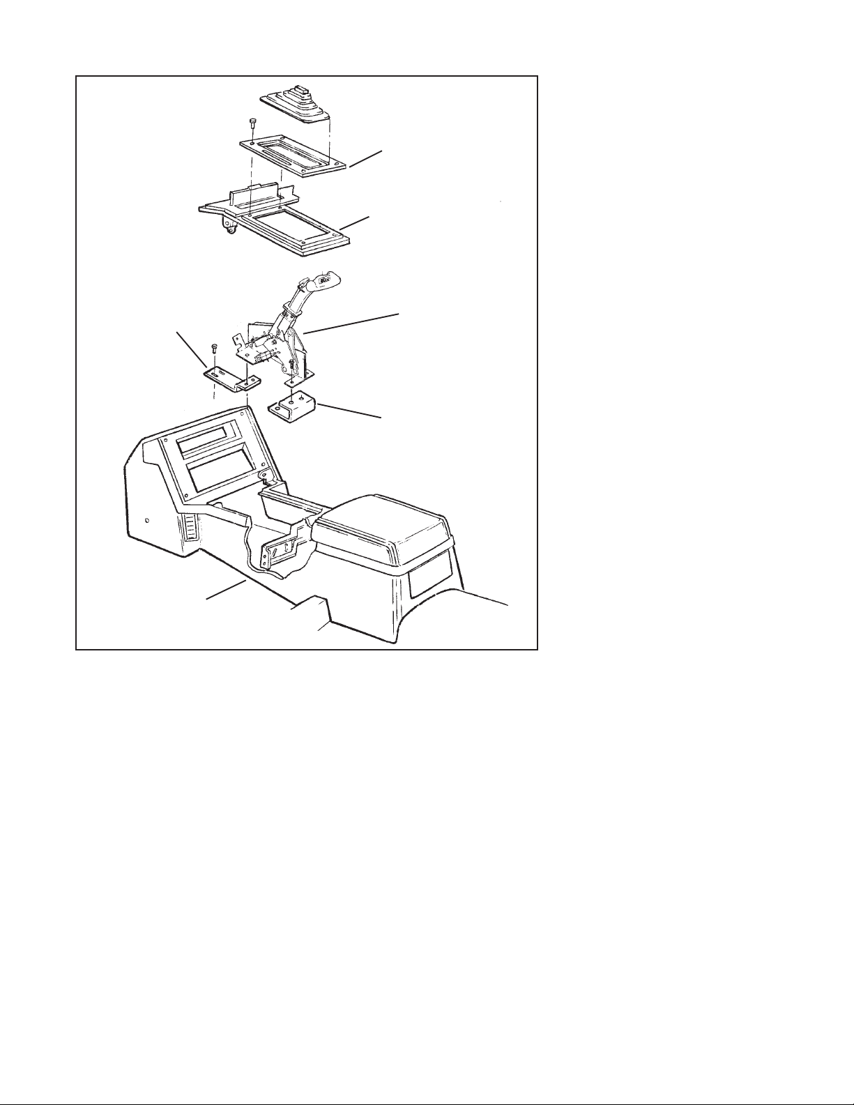
Front mounting
bracket
GM console
Figure #1
the end of the cable. Install two rubber boots
onto the end of the cable. Install the swivel on
the threaded end of the cable and position it
in the center of the threaded portion.
STEP 13. Move the transmission selector
lever by hand to full rear position (Low).
Operate the shifter lever to the Low gear
position (ratcheted all the way back). Adjust
the large nuts on the cable so that the swivel
will slide into the front hole on the selector
lever. Tighten the large nuts completely. Be
sure that the swivel will slide freely in and out
of the hole in the selector lever. Note: The
shifter will not operate correctly unless
the front hole in the shift lever is used.
Leave the swivel out of the hole and move
the selector lever to Park, all the way forward. Also move the shifter to the Park
position (all the way forward). Reinsert the
swivel into the front hole in the selector
lever. Check to see that the swivel will slide
freely in and out of the front hole in the
selector lever in this position. If it does not slip
in freely, adjust the swivel slightly until it will
slip into the hole in the lever.
Move the shifter back to the Low gear
B&M cover
plate
GM console
top cover
B&M shifter
Rear mounting
bracket
position and check that the swivel will still
slide easily in and out of the front hole in the
selector lever. Operate the shifter through all
the gear positions. Check to make sure the
swivel will slide in and out of the front
selector lever hole in each gear position. The
shift cable is now correctly adjusted. Install
the cotter key supplied with the shifter into the
swivel and spread the key ends.
If you have a problem, DO NOT FORCE
THE SHIFTER, this will damage the cable,
the shifter or the transmission. Simply start at
the beginning and carefully check all your
steps.
STEP 14. Disconnect the battery ground cable
before beginning to wire the neutral start and
reverse light switches. Locate and identify
the neutral start and reverse light wires on the
stock wiring plug removed in Step 4. Cut
wires from plug then strip 1/4" insulation off
the wires and lengthen them with 4-6" of
additional wire. Put slip-on terminals on the
end of the lengthened wire. Crimp the terminals onto the wires using a crimping tool or
pliers. Connect the neutral start wires (the
purple and yellow wires) to the LOWER
2
switch and the reverse light wires (dark blue
and light green) to the UPPER switch (See
Figure #2). Tape the terminal connections to
prevent shorts. Reconnect the battery ground
cable, disconnect the coil wire and set the
parking brake. Check the switch operation by
attempting to start the motor in each shifter
position. The starter must crank only
when shifter is in the Park or Neutral
position. Check the reverse light operation.
Adjust the switches if required. Reconnect
the coil wire.
Note: Some models will have two additional
wires, orange with black and black with
white going to the plug. Do not join these
wires. Tape the ends of these wires separately to prevent grounding. With the factory
shifter, these are switched together in the
Neutral and Park positions. This circuit locks
out the converter clutch and changes the idle
speed. This circuit can be restored by the
addition of the supplied relay operated by the
neutral safety switch circuit (See Figure
#6). The relay is a Double Pole Single Throw
relay for 12 VOLTS DC operation and has a
30 amp rating (minimum one amp required).
STEP 15. Cut the bulb socket from the stock
console light. These wires will be connected
to the indicator light on the shifter. Remove the
indicator assembly from the stock console
cover plate. A small file or a hot knife works
well.
STEP 16. Place the supplied template on top
of the GM console top cover. On the Camaro,
locate the holes marked “A” over the four
stock holes around the shifter opening. On
the Firebird, locate it with the two holes
marked “B” over the stock screw holes. Tape
the template onto the cover plate and transfer
the cutout shape to the cover with a scribe or
felt tip marking pen. Drill 1/4" holes in the
corners of the rectangular area. Cut away a
rectangular area with a key hole saw. File or
sand the edges of the cut.
STEP 17. Install the GM console top cover,
using the original hardware. Feed the B&M
top plate through the hole in the cover.
STEP 18. Install the indicator light bulb in its
socket on the shifter cover plate. Connect the
wires that were cut in Step 15.
STEP 19. Snap the shift position window into
the top plate. The window snaps in from the
top with the tabs inserting into the slots at
either end of the window opening. Place the
shifter in the Park position then remove the THandle from the shifter. Place the cover plate
over the stick and onto the top of the tower.
Route the indicator cable around the front of
the shifter so that it has a free radius and will
not bind. Run the shifter through all of the
gears to check the operation of the indicator.
If the indicator needs adjustment, loosen the
screws holding the indicator cable clamp to
the cover plate and slide the cable bracket to
adjust the indicator position. (Retighten these
screws carefully since they are threaded
into plastic.) Attach the cover plate to the
tower with four Phillips head screws.
STEP 20. Slide the boot over the stick and
install it into the cover plate. Note that the front
Page 3

of the boot had “FRONT” on the inside of the
rubber. After the boot is installed in the cover
plate and into the stick, install the T-Handle
and the jam nut. Tighten the jam nut when the
handle is properly oriented.
OPERATION
The B&M Megashifter normally functions as a straight gate detent shifter from
Park to Reverse to Neutral to Drive and as a
ratchet shifter from Neutral to all forward
gears. Refer to the following instructions for
proper operation:
STRAIGHT GATE MODE: With the trigger in
the upper position, the shifter functions in the
STRAIGHT GATE mode. The handle travels in
a direct line forward and backward from Park
to Drive. The trigger must be raised up to clear
the stop gates while going through the gear
positions.
RATCHET SHIFT MODE: The RATCHET SHIFT
mode allows firm, positive no-miss upshifts
and downshifts through all positions from 1
(Low gear) to Neutral. To switch from
STRAIGHT GATE to RATCHET operation, first
operate shifter to the Drive position. The
trigger will snap down approximately 3/4".
The shifter is now in the RATCHET mode,
Drive gear position. The shifter will only operate in the RATCHET mode between Neutral
and Low, it will not ratchet to Reverse or Park.
This is done to prevent accidental shifting into
Reverse.
SHIFTING IN THE RATCHET MODE: Move the
Remove this blocker pin
and E-clips with four
speed transmission
1/4" nut
1/4" lockwasher
Cable pin
1/4" x 1/2"
bolt
Cable attaching tab goes on
outside surface of shifter base
Figure #2
shift handle forward or backward with a
quick firm action until it hits the internal stops,
and allow it to spring return to the center
position. The shifter is now ready for the next
shift.
To switch the shifter from RATCHET mode
back to the STRAIGHT GATE mode, operate
the shifter to the Drive gear position, pull up
firmly on the trigger to engage the STRAIGHT
GATE mode and move the handle forward to
Neutral, Reverse and Park.
REMEMBER: To switch from the STRAIGHT
Remove this blocker pin
and E-clips with four
speed transmission
Backup light
switch
E-clip
Neutral safety
switch
GATE mode to the RATCHET mode or from
RATCHET mode to STRAIGHT GATE mode
you must be in the Drive gear position. Refer
to the shift indicator gear position.
SPECIAL NOTE: If the instructions for operating your shifter seem complicated, DO NOT
BECOME ALARMED. You will find that in
actual use the shifter will be extremely easy
to operate after a minimal amount of experience. Caution: The shifter is an important
controlling mechanism of your vehicle and
can create serious driving hazards when
any part is loose, missing or misadjusted.
After you have installed your shifter we
recommend you review the instructions to
assure a complete and proper installation.
E-clip
Indicator
Note: Sharp bends will kink and damage
Route cable
cable
Washer (2)
Bracket
Figure #3
Sheet metal
screw (2)
Figure #4
WARNING
PERIODIC INSPECTION AND MAINTENANCE OF YOUR SHIFTER IS RECOMMENDED TO ENSURE THAT
THE MECHANISM IS WELL LUBRICATED, FREE FROM DIRT OR RUST AND THAT THE CABLE IS
PROPERLY ADJUSTED. LACK OF MAINTENANCE COULD RESULT IN A FAILURE INCLUDING A FAILURE
OF THE REVERSE LOCKOUT SAFETY FEATURE.
3
Page 4

GM Transmissions
F
Cable swivel
Cotter pin
(Use front hole)
Check List
___ Ignition/steering column lock works cor-
rectly. Key can be removed and steering column locks when key is removed.
Step 4.
___ Cable is securely fastened to shifter
and end is held with E-clip. Step 6.
___ Cable is routed as shown in Figure 4 and
securely fastened to transmission and
swivel is held with cotter key. Step 12.
___ Shifter is properly adjusted. Step 13.
___ The neutral start and reverse light
switches are connected and properly
adjusted to prevent engine from starting
in forward gears and reverse. Step 14.
___ There is no debris in shifter mecha-
nism.
___ Cover plate is securely fastened and
shift position indicator is operating prop-
erly. Step 20.
___ Shifter moves freely in all positions as
described in Shifter Operation.
___ If your shifter is not working properly
do not attempt to drive your vehicle.
Make sure you have followed all in-
structions. If the shifter is broken or
defective return it to your B&M dealer.
R
C
GM lever
5/16 x 1" bolt and spacer
(Metric trans use M8 x 25 bolt)
GM cable bracket
7/16" nut
Figure #5
1 Common Screwdriver
1 Phillips Screwdriver
1 #15 Torx bit or driver
1 10mm Wrench
1 1/4" Wrench
1 5/16" wrench
2 7/16" Wrench
1 9/16" Wrench
2 11/16" Wrench
1 10mm Socket and ratchet
Use these two holes for
TH-400 transmission. Use
other two holes for other
GM transmissions
Spacer
GM cable bracket (Trimming of bracket
required if used on cast aluminum pan)
Tool List
1 1/8", 9/32" and 1/4" Drill Bits
1 Drill Motor
2/4 Jack Stands
1 0-50 lb.ft. Torque Wrench
1 File
1 Wire Stripper
1 Wire Crimper
1 Pliers
1 Electrical Tape
A/R Nylon Tie Wraps (to secure cable)
TYPICAL PIN
NUMBER
Typical Pin
Number
24
21
14
6
2
5
11
8
4
14
8
A1
01
13
12
9
A2
IMPORTANT
Before installing the T-handle onto the
shifter put a little grease on the threads of
the stick. The aluminum of the T-handle
may gall on the threads of the stick and
make it impossible to remove the T-handle
from the stick. If this occurs it can cause
the stick to break if you use excessive
force while attempting to remove the Thandle from the stick.
GND
RELAY DPST
NORMALLY OPEN
12VDC
(SUPPLIED)
Figure #6
4
 Loading...