

Page 1

Installation Instructions
TH-700R4 (4L60) Transmission
with 30 tooth input shaft spline
Part Number 117101, 117102, 117103, 107101, 107104, 117301, & 117302
©2002, 2001, 1999, 1994 by B&M Racing and Performance Products
The B&M TH-700R4 is a specially modified transmission
intended for performance and heavy duty applications. It
is suitable for use behind engines producing up to 450 lbft of torque. This covers most small block Chevrolets and
mild big blocks.
1982-85 and some 1986-87 TH-700’s controlled the Torque
Converter Clutch (TCC) with hydraulic valves located in
the valve body . In most 1986 and later TH-700’s the TCC
shift valve was plugged and TCC is controlled by an Electronic Control Module (ECM). ALL B&M TH-700 (4L60)
TRANSMISSIONS ARE BUILT FOR ECM CONTROL OF
THE TCC. If you are replacing a 1982-87 transmission
with hydraulic TCC control you will have to do one of the
following: Swap valve bodies from your original transmission to he new one or, purchase an electronic TCC control
(B&M P/N 70244). For installation into vehicles not originally equipped with a TH-700, see Section 2 for instructions on how to control the T orque Converter Lockup clutch.
A lockup torque converter is desirable but not required
with this transmission. To prevent the transmission from
overheating adequate oil cooling is required especially if
running an open (non-lockup) converter. If you are installing a non-lockup torque converter you must also disconnect the TCC Solenoid to maintain proper oil flow in the
converter (refer to instructions accompanying the nonlockup converter). The torque converter for this transmission must have a 30 tooth spline turbine hub. B&M offers
a complete line of converters for a wide range of performance and towing applications. See the B&M catalog for
the latest offerings including the T ork Master and Holeshot
torque converters.
The TH-700 (4L60) transmission does not use a vacuum
modulator like some GM transmissions. Instead it uses a
Throttle V alve (TV) linkage mechanism to control line pres-
Printed in the U.S.A.
sure. It is essential that the TV cable be attached to the
carburetor or throttle body and properly adjusted. If the
cable is not connected correctly , the transmission will not
shift correctly and it may fail. See Section 3 for instructions on connecting the TV cable in vehicles not originally
equipped with a TH-700.
1. TRANSMlSSlON INST ALLA TION
STEP 1: Assemble torque converter to transmission. Lu-
bricate the torque converter pump drive hub with clean
transmission fluid before installation.
STEP 2: The engine block’s transmission mounting face
must be free of any dirt or burrs. Make sure both dowel
pins are Installed and stick out of the block approximately
1/2” to insure proper transmission alignment.
STEP 3: Remove and inspect the flexplate for distortion,
cracks or damaged ring gear teeth. If the flexplate shows
any damage it should be replaced. Do not attempt to repair a damaged flexplate.
STEP 4: Assemble the flexplate to crankshaft and align
all holes before installing the bolts. When properly installed
the raised inner lip on the flexplate should face away from
the crankshaft flange. Torque the bolts to 81 Nm (60 ft.lbs.).
STEP 5: Place the transmission in position on transmission jack. Make sure the jack supports the transmission
on a wide area so the oil pan is not crushed. Install the
transmission / converter against the engine. The transmission should engage the dowel pins and sit flat against
the block with hand pressure only . If the transmission does
not sit flat against the engine, the converter is not fully
engaged in the transmission or some other interference
problem exists.
WARNING: Do not attempt to pull the transmission
9500377-04
Page 2
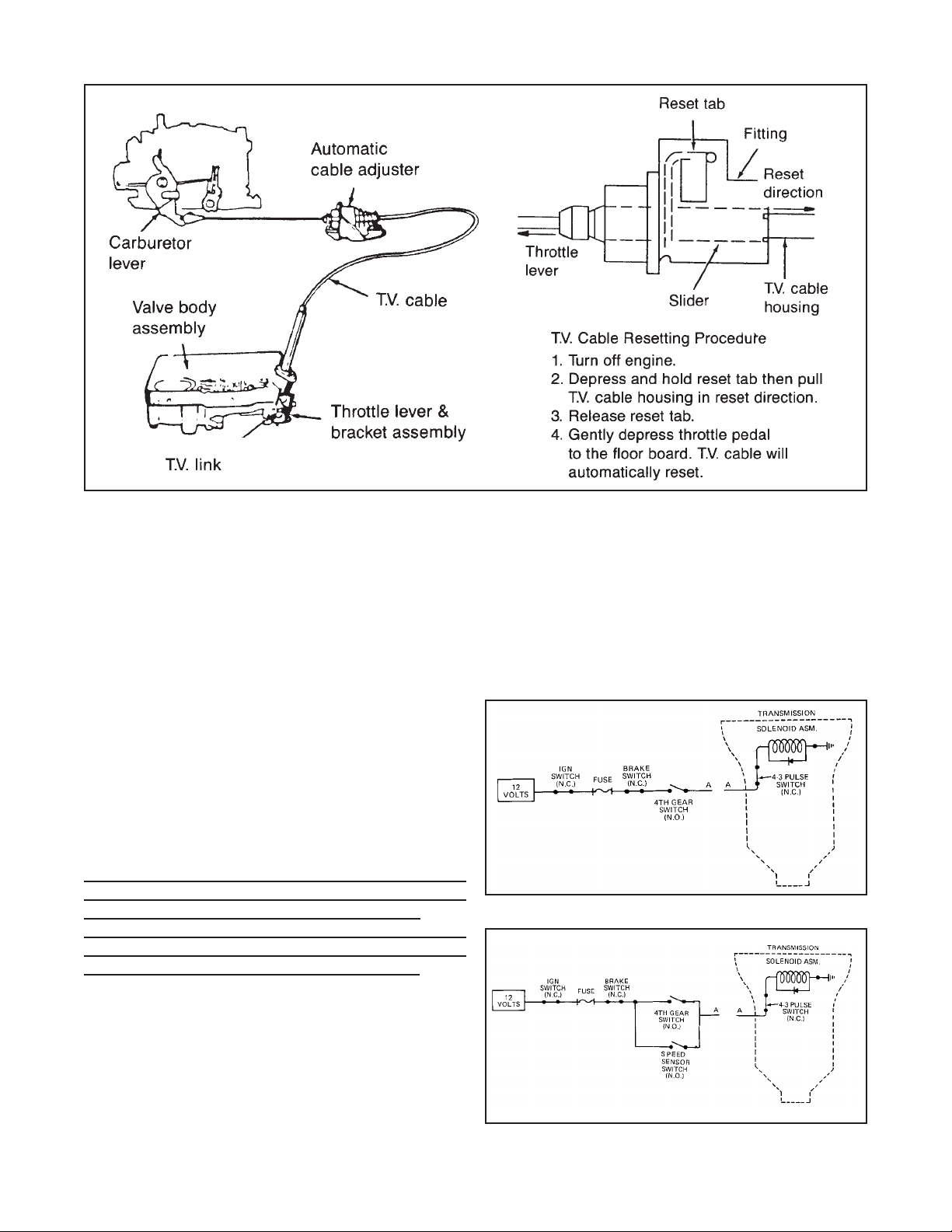
FIG. 1 Resetting T.V. Cable
up to the engine with the bellhousing bolts as this
can cause transmission or torque converter damage.
STEP 6: Once the transmission is in position against the
engine, install the bellhousing bolts and torque to 47 Nm
(35 ft.lbs.). At this point the torque converter should turn
freely .
IMPORTANT: A tight converter indicates improper engagement, a distorted flexplate or binding pilot hub. This con-
dition must be corrected before going further.
STEP 7: Inspect transmission mount. Worn, cracked or
broken transmission and/or engine mounts should be replaced. Raise transmission and install crossmember assembly then tighten all bolts. Install three (M10 x 1.5 x
15) flexplate to converter bolts. Install the first bolt finger
tight then use the starter motor to “bump” each drive lug
into position. When all three bolts are installed torque
them to 47Nm (35 ft.lbs.).
STEP 8: (FIG. 1) Reconnect and adjust the TV cable.
WARNING: You must reset the TV cable before operating
the transmission. Failure to reset the TV cable will result
in poor shift quality and early transmission failure.
IMPORTANT: If you are using the transmission in any
type of custom installation see Section 3 for details on
how to set up the T.V. cable so it works correctly.
STEP 9: Connect speedometer cable, electrical connector and shifter cable. Make sure the cooler tube connector fittings are tight in transmission case first, then connect cooler lines and tighten the tube compression nuts
with a fitting wrench to avoid damaging the nuts.
STEP 10: Install drive shaft (and torque arm if used). Make
sure the U joint cups (bearings) are properly positioned in
their seats. T ighten U joint nut s or bolts securely.
STEP 11: Lower vehicle but keep the rear wheels of f the
ground if possible. Add six (6) quarts of B&M TRICKSHIFT
or DEXRON® III fluid to the transmission. Place transmission in NEUTRAL and start the engine. Add fluid to transmission until the fluid level is between the FULL and ADD
marks. Shift the transmission through all gear positions.
If the wheels are off the ground, allow the transmission to
shift through all gears several times. Place selector in
NEUTRAL and check the fluid level again. DO NOT OVER-
FIG. 2 4th Gear Only TCC Wiring
B&M 70244 or 70248
FIG. 3 Speed Sensor Controlled TCC Wiring
2
Page 3
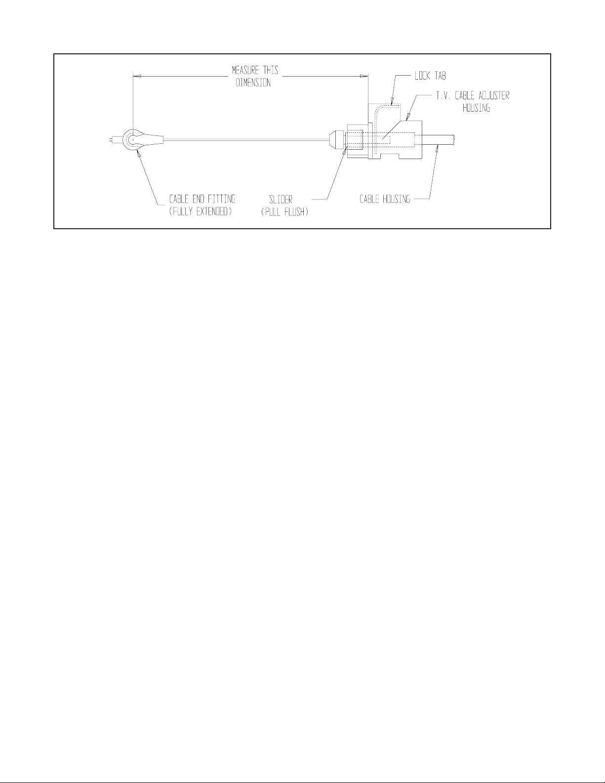
FIG. 4
FILL. Check for leaks around the oil pan, cooler lines,
etc.
2. CONTROLLING THE TORQUE CONVERTER
CLUTCH ENGAGEMENT
In stock applications the torque converter clutch (TCC)
engagement is controlled by either a speed dependent
hydraulic pressure signal from the TCC shift valve train or
ECM control depending on the valve body configuration.
When this control signal is present and the TCC solenoid
is energized the TCC Apply valve (located in the Oil Pump
Body) moves to engage the TCC. In most non-stock applications the ECM signal is not available to signal TCC
engagement. The TCC engagement on your B&M transmission is controlled electrically .
There are two approaches to control the TCC. In the first
and simplest, the TCC solenoid is wired in series with a
normally open pressure switch in the 4th gear circuit (see
FIG. 2) and a switch attached to the brake pedal. With
this arrangement TCC engagement occurs when the transmission shifts to 4th gear , also the TCC is automatically
disengaged when the brake pedal is depressed. See (FIG
2) for an example wiring diagram.
The second approach is to install a speed sensing device
(such as B&M P/N 70244 or 70248) which controls the
TCC engagement as a function of vehicle speed. This allows TCC engagement to be adjusted to occur any speed
or gear (above 1st) which may be desirable for fuel
economy considerations. As a safety precaution a pressure switch should also be installed in the 4th gear circuit
that acts in parallel with the speed sensor switch. The
pressure switch will insure TCC engagement in 4th gear
should the speed sensor switch become misadjusted or
inoperative. See (FIG . 3) for an example wiring diagram.
3. THROTTLE V AL VE MECHANISM
The purpose of the TH700-R4 Throttle V alve (T.V .) and it’s
mechanical linkage is to control both the shift feel and
shift timing as a function of vehicle speed and load conditions. As the accelerator pedal is depressed and the throttle
opens, the T.V. mechanical linkage relays the motion to
the throttle plunger in the valve body by way of the T.V.
cable. In factory installations of the TH700-R4 the geometric relationship between the T.V. cable and throttle
shaft bellcrank produces the required T.V. cable extension (pull) to throttle opening for the transmission to function properly . In custom installations the correct T . V . cable
mounting geometry must be accurately determined if the
transmission is to function properly. It cannot be overstated that for the TH700-R4, proper T.V. cable installation and adjustment are paramount to proper transmission function and life. If the T.V. cable is not operating
correctly , the transmission life will be greatly reduced.
The following procedure will show you how to design a
custom T.V. Cable installation that works. The main objective is to accurately position the T.V. cable mounting
bracket in relation to the throttle shaft axis to obtain the
proper T .V. CABLE EXTENSION (PULL) TO THROTTLE
OPENING relationship.
STEP 1. Measure your T.V . cable to establish it’s particular mounting dimension (there are several lengths in use)
as follows (see Fig.4). Retract the slider by depressing
the lock tab then pull the cable housing until the flats on
the slider are flush with the end of the adjuster housing
then fully extend the cable by pulling the cable end fitting
out (slider must remain retracted) until it stops. Holding
the end fitting out, measure the dimension from the face
on the adjuster housing that registers with the mounting
bracket to the center of the cable end connector.
STEP 2. Add 3/16” (0.19 in.) to the measurement obtained
in Step 1 , this is the perpendicular measurement from the
REAR FACE of the T.V. cable mounting bracket to the
WIDE OPEN THROTTLE position of the T.V. cable connector pin on the throttle bellcrank (see Fig. 5).
STEP 3. The T.V . cable bellcrank must be perpendicular
(90 degrees) to the T .V. cable when the throttle is 25 percent (1/4) open (see Fig. 5), this geometric relationship is
3
Page 4

FIG. 5
FIG. 6
critical to insure that the T.V. mechanism moves in the
correct proportion to the throttle opening. The mounting
location for the T.V. cable connector pin will have to be
established on the throttle bellcrank at a radius of 1.094 /
1.125 in. There may a suitable existing hole at the correct
radius on the throttle bellcrank, otherwise you will have to
fabricate an attachment to the bellcrank that will properly
locate the connector pin.
Diagrams of several typical factory installations are shown
for reference (see Fig. 6). Notice the geometric relationship between the T.V. cable bellcrank (attached to the
carburetor or the throttle body) and the mounting bracket.
Several things should be kept in mind during this stage of
the design:
1. The proper location of the T.V . cable mounting bracket
is determined by the angular and radial position of the
T.V. cable connector pin on the throttle bellcrank.
2. Make sure that all of the cables or rods that will be
attached to the throttle bellcrank do not interfere with
each other when the throttle is advanced from idle to
wide open.
3. Mount the T .V . cable adjuster housing so that the lockt ab
is readily accessible and not blocked by other cables,
rods, brackets or other engine mounted accessories.
STEP 4. Fabricate T.V . cable bracket using 0.090 - 0.125
in. sheet metal (see Fig. 7) for the adjuster housing cutout dimensions. If you use the thicker stock a chamfer
will be required on two sides of the cable mounting cutout
to allow the lock tabs to expand properly. The T.V. cable
adjuster requires a pull of about 18 lbs. to ratchet out, so
try to make the mounting bracket as rigid as possible. If
the mounting bracket flexes the T.V. pressure will not be
consistent.
4. SERVICE & DIAGNOSIS
GENERAL TRANSMISSION DESCRIPTION
The TH700-R4 is a fully automatic transmission for rear
wheel drive vehicles which provides four forward gear ranges
FIG. 7
4
Page 5

and reverse.
The oil pressure and shift points are controlled by the
throttle opening via the Throttle V alve cable.
The transmission can be operated in any of the seven
different modes.
P Park position prevents the vehicle from rolling either
forward or backward. (For safety reasons the
parking brake should be used in addition to the Park
position.)
R Reverse position allows the vehicle to be operated in
the rearward direction.
N Neutral position allows the vehicle to be started and
operated without driving the vehicle. If necessary this
position may be selected - the engine must be restarted
with the vehicle moving.
D Overdrive position is used for all normal driving condi-
tions. It provides four gear ratios plus converter clutch
operation. Downshifts are available for safe passing by
depressing the accelerator pedal.
3 Drive position is used for city traffic, hilly terrain, and
trailer towing. It provides three forward ranges plus converter clutch operation. Downshifts are available for safe
passing by depressing the accelerator pedal.
2 Manual second position is used to provide accelera-
tion and engine braking. This range may be selected at
any vehicle speed.
1 Manual Low position is used to provide maximum en-
gine braking.
E. Uses such as found in taxi or police car .
If you do not use the vehicle under any of these conditions, change the fluid and filter every 50,000 miles (80,000
km). It is also a good idea to check the torque converter
bolts when servicing the transmission.
TH-700 R4 FLUID CAP ACITY
Pan Removal 10.0 pints
Overhaul 23.0 pints
PRELIMINARY DIAGNOSIS PROCEDURE
1. Check and correct fluid level.
2. Check T.V. cable adjustment. It’ s a good idea to readjust the T.V. cable prior to test driving or checking line
pressures.
3. If engine performance indicates an engine tune-up is
required, this should be completed before road testing
is completed or transmission correction is attempted.
Poor engine performance can be mistaken for transmission problems.
4. Check and correct vacuum lines and fittings.
5. Check and correct shifter manual linkage.
6. Install oil pressure gage and check line pressures.
Compare with values from the appropriate table.
ROAD TEST PROCEDURE
SERVICE
Because of the tremendous pressures and heat developed in the TH700 in high performance applications you
should check the transmission fluid’s condition frequently .
When checking the fluid’s condition consideration should
be given to the type of service the transmission has been
subjected to. Under normal conditions the fluid will discolor slightly and should be changed at the recommended
service interval. Fluid that is dark in color and smells burnt
is usually the result of repeated upshifts and/ or downshifts under heavy load and/or wide open throttle operation. Such demanding operation will require even more
frequent oil changes to ensure reasonable transmission
life. If the fluid’s condition (color and smell) is not indicative of the type of service in which the transmission has
been used then a more serious problem exists and should
be repaired.
For best performance and life of your TH-700 we recommend changing both the fluid and filter every 15,000 miles
(25,00 km) if the vehicle is primarily driven under one (or
more) of the following conditions:
A. High performance applications where the vehicle is regu-
larly driven hard.
B. In heavy city traffic where the outside temperature regu-
larly reaches 90 F (32 C) or higher.
C. In hilly or mountainous terrain.
D. Frequent trailer pulling.
OVERDRIVE RANGE: While stopped, position the range
selector in the Overdrive position then accelerate. Check
for 1-2, 2-3, and 3-4 upshifts. (Shift points will vary with
throttle position.) Also, the converter clutch should apply
in second or third gear range depending on calibration.
(Calibration depends on the components installed in the
valve body at the factory.) Check for part throttle downshifts by depressing the throttle to a 3/4 open position.
Check for detent downshifts by depressing the throttle to
wide open position at various vehicle speeds.
DRIVE RANGE: At road speed in fourth gear (Overdrive
range), manually shift the transmission to the Drive range.
The transmission should downshift to 3rd gear range immediately . Check for part throttle and detent downshift s.
DRIVE 2: While in 3rd gear range, shift to manual second, the transmission should downshift immediately . T est
for a 2-1 detent downshift.
LOW RANGE: Position the selector lever in Low range
and check operation. (In some vehicles it may be possible to obtain a 1-2 upshift with selector in this gear range.)
OVERRUN BRAKING: Overrun braking can be checked
by manually shifting to a lower gear range. Engine R.P .M.’ s
should increase and a braking effect should be noticed.
There is no overrun braking in Fourth (overdrive) range.
REVERSE: Position selector in the reverse position and
check reverse operation. The TCC does not engage in
Reverse.
5
Page 6

ADDENDUM
Shift Speed Adjustment:
All of our transmissions are built with standard V8 shift points. Some Installations may require adjusting the shift
points Up or Down for proper operation. There are two approaches to remedy this problem;
1. Swap the governor from the original transmission (after through cleaning).
2. Use the included (P/N 20248) Governor recalibration kit.
117101, 117102 & 117103
Street Level T ransmissions Only
1-2 Shift feel:
1-2 shift feel can be made firmer by installing the supplied 1-2 Accumulator spacers. Y ou will have to
remove the oil pan and 1-2 accumulator housing to install the spacers (see figure A1).
T orque Accumulator Housing
Bolts to 11 NM (8 lbs.ft.)
Figure A1. Street Level Accumulator (firmer feel)
Torque Oil Pan Bolts to 14 Nm (10 lbs.ft.)
6
Page 7

OIL PRESSURE CHECK PROCEDURE
PRELIMINARY CHECK PROCEDURE
* CHECK TRANSMISSION OIL LEVEL
* CHECK AND ADJUST T.V . CABLE
* CHECK OUTSIDE MANUAL LINKAGE
* CHECK ENGINE TUNE
* INST ALL 0-300 PSI PRESSURE GAUGE
* CONNECT T ACHOMETER TO ENGINE
* CHECK OIL PRESSURE AS FOLLOWS
MINIMUM T .V . LINE PRESSURE CHECK:
With the T.V. Cable properly adjusted and the brakes
applied, take the Line Pressure readings in the Ranges
and at the engine RPM’s indicated in the chart.
Oil Pressure T ap Locations
FULL T .V . LINE PRESSURE CHECK:
Full T.V. Line Pressure readings are obt ained by holding the T.V . Cable to the full extent of it’ s travel then take the
Line Pressure readings in the Ranges and at the engine RPM’s indicated in the chart.
CAUTION: Limit running time at FULL T.V . Pressure to two (2) minutes maximum to prevent overheating.
CAUTION: Brakes should be applied at all times.
TH700-R4 TRANSMISSION OIL PRESSURES
4th Oil press Tap is not
present on all models
NORMAL OIL PRESSURE
RANGE
P ARK, NEUTRAL,
OVERDRIVE,
MANUAL 3RD
@1000 RPM
REVERSE
@1000 RPM
*@2000 RPM
MANUAL 2ND &
MANUAL LOW
@1000 RPM
NOTE: Oil Pressure at FULL T.V. Pressure depends on the particular T.V. Boost valve and Line Bias Valve
arrangement of the unit. The Pressure reading obtained should be within the range shown.
Base Line Pressure is controlled by the Pressure Regulator V alve and Spring. Line Pressure is boosted a fixed
amount by the Reverse Boost valve when the selector lever is placed in Second or Low Range. The Line Pressure
is also boosted in Neutral, Drive, Drive3 and Reverse with throttle opening because of the T.V. system. The
pressure is controlled by the T .V. Cable via the throttle Lever and Bracket assembly to the V alve Body assembly .
MODEL
ALL MODELS SEE
NOTE BELOW
ALL MODELS SEE
NOTE BELOW
ALL MODELS SEE
NOTE BELOW
A T MINIMUN T.V .
kPa kPaPSI
517-586
862-955
1517-1689
75-85
100-140
160-295
NORMAL OIL PRESSURE
AT FULL T.V.
PSI
1 145-1400
1869-2296
1517-1689
166-203
180-340
160-295
The Line Pressure tap is located on the left side of the transmission case above the outside Manual Lever .
FIG. 8 Oil Pressure Check Procedure
7
 Loading...