

Page 1

Installation Instructions
Shift Improver Kit
1965-1987 Turbo Hydra-Matic 400
TH-400/TH-475 (3L80/3L80-HD)
Part Number 20260
© 2000, 2001 by B&M Racing & Performance Products
IMPORTANT NOTICE: HydraMatic introduced a revised transmission case just after the beginning of the
1988 model year. If you are installing
the B&M TH-400 Shift Improver Kit in
a late model vehicle which has had the
transmission replaced after 1988 you
must check the Julian date stamped on
the transmissions I.D. tag (See Fig. 1)
before attempting to install this kit. Do
not use this kit (#20260) in transmissions built on or after November 23,
1987 (Julian date 327), use instead our
#20261 Shift Improver Kit which is
designed to be used with the new style
case. If the I.D. tag is unreadable or
missing you will have to remove the oil
pan and valve body from the transmission to determine if your transmission
has an early or late style case (See
Fig. 2). This kit (#20260) will work
correctly in all 1965 through 1987 TH400 transmissions.
We recommend that you read
through the instructions completely
before beginning the installation so
you can familiarize yourself with
the installation procedure and tools
required.
Check the tool list at the end of
these instructions for the tools required to install your B&M TH-400
Shift Improver Kit.
Installation of the B&M TH-400 Shift
Improver Kit can be accomplished by
anyone with minimum mechanical experience. It is however, important to
closely follow the instructions. Read
each step carefully before proceeding,
if you do not understand, go back and
read the step again.
NOTICE: The B&M TH-400 Shift Im-
prover Kit is not a cure-all for an ailing
transmission. If your transmission is
slipping, chatters or is in poor general
shape, the installation of this Transpak
may worsen the condition. However on
a properly operating transmission in
average condition, the B&M TH-400
Shift Improver Kit will provide the kind
of transmission performance you are
looking for.
When installing your B&M TH-400
Shift Improver Kit there are several
other B&M performance products you
may wish to consider:
TRANSMISSION OIL COOLER We
feel that it is very important that every
vehicle used in heavy duty and hi performance applications (racing, towing,
RV, etc.) should have an oil cooler.
Heat is the major cause of transmission failures, and an oil cooler is an
inexpensive safeguard against overheating and transmission failure. B&M offers a wide variety of transmission cool-
ers to suit every application.
TRICK SHIFT PERFORMANCE ATF
#80259 Trick Shift performance auto-
matic transmission fluid is the industry’s only real performance ATF. A
specially blended oil with foam inhibitors, extreme pressure agents and
shift improvers, this fluid assures protection while delivering the fastest possible shifts. You literally “Pour in performance.”
DRAIN PLUG KIT #80250 The TH-400
transmission is not factory equipped
with a drain plug. The B&M Drain plug
kit is inexpensive and easy to install. It
eliminates the mess of pan removal and
gasket replacement normally required
when changing fluid.
DEEP PAN #20289 B&M offers deep
pans for the TH-400 transmission that
provide 3 to 4 quarts additional oil capacity which significantly contributes
to the cooling ability of the oil. No
modifications to the dip stick are necessary and a fluid pickup extension is
provided.
TORQUE CONVERTERS B&M offers
a wide range of street torque converters for the TH-400 transmission. See
your B&M dealer for details of the
correct torque converter for your vehicle.
ADJUSTABLE VACUUM MODULATOR
Printed in the U.S.A.
9500019-11
Page 2
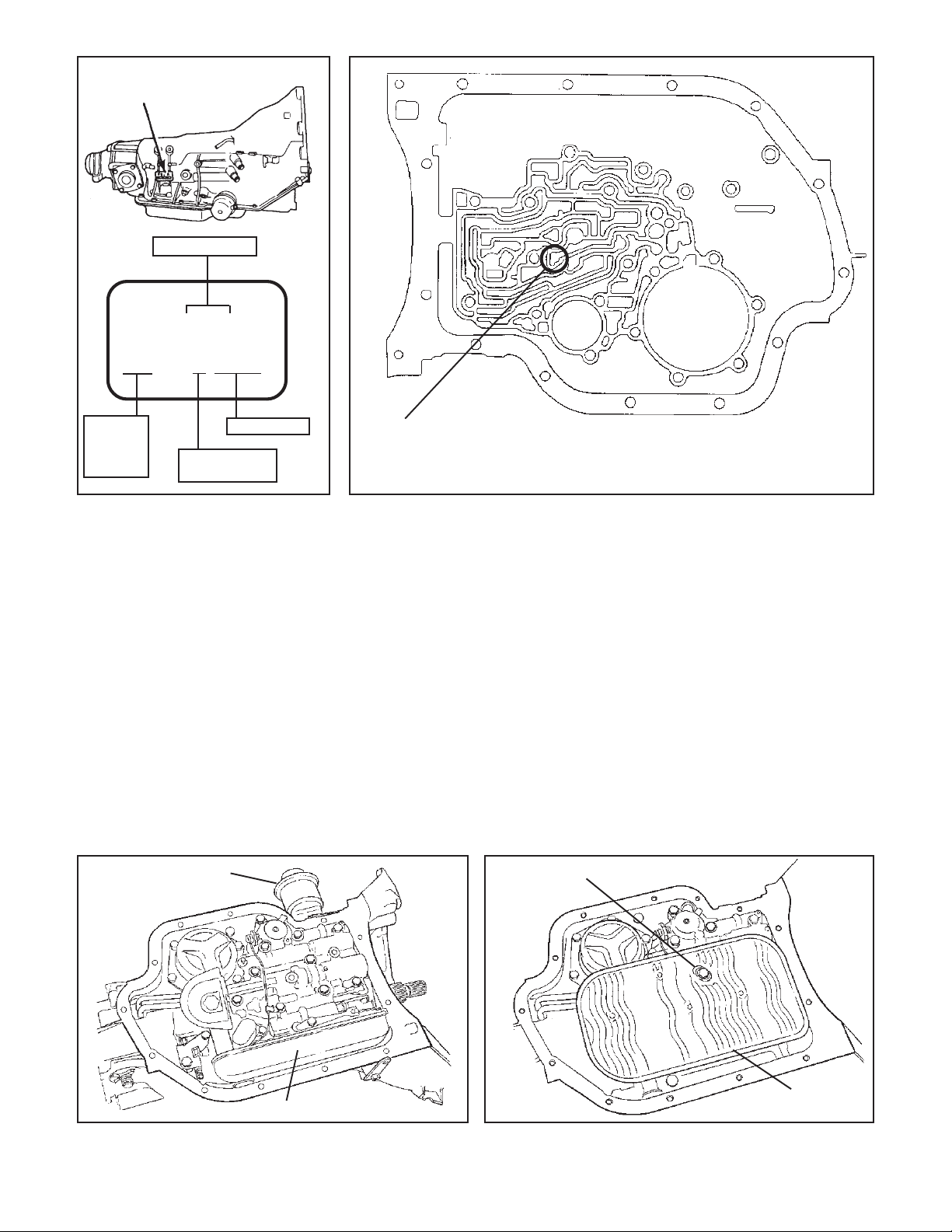
Transmission I.D.
Nameplate Location
JULIAN DATE
QU 000 A
80 QUA 0000
Model Year
80=1980
83=1983
86=1986
Figure 1
#20234 This replacement vacuum
modulator for the TH-400 has the added
feature of being adjustable. The adjustable feature allows you to tailor your
shift points within a range of 2-4 mph.
FILTER SERVICE KIT #20287 The filter service kit replaces the stock factory filter with a special filter that uses
a much finer felt micronic element which
also has more total filter area so that
the finer filtering element does not cut
down on oil flow. This kit includes a
special heavy duty oil pickup tube that
is seated to the case with a double Oring seal and is spring loaded to eliminate air leakage.
TEMPERATURE GAUGE KIT #80212
Most transmission and converter fail-
Vacuum modulator
Serial Number
A= TH-400/475
(3L80/3L80-HD)
The 1988 and later TH-400 has a checkball in this location and must
use Shift Improver Kit (#20261). If you have no checkball in this
location, this kit (#20260) is the correct one.
Figure 2
ures can be traced directly to excessive heat. The B&M transmission temperature gage can save you a costly
repair bill by warning you ahead of time
of an overheated transmission. The B&M
temperature gage is extremely accurate and dependable, it comes with all
necessary hardware and is easy to
install.
B&M SHIFTERS; B&M manufactures
a complete line of automatic transmission shifters ideally suited for use with
the TH-400. These shifters provide you
with positive transmission control as
well as stylish appearance for your
vehicles interior.
TH-400 KICKDOWN SWITCH #20297
When installing a TH-400 transmission
Remove bolt to remove filter
in a custom installation in place of a TH350 or a TH-700 this kit provides a
kickdown switch that will fit into the TH350 or TH-700 throttle cable bracket.
INTRODUCTION
The B&M TH-400 Shift Improver
Kit can be installed in a few hours by
carefully following the instructions.
Transmission components are precision fit, work slowly and do not force
any parts. Burrs and dirt are the number
one enemies of an automatic transmission. Cleanliness is very important, so
a clean work surface from which oil can
easily be removed is necessary.
This kit contains all the parts nec-
essary to obtain two different levels of
Filter, 1965-67 models
Figure 3 - 1965-67 Figure 4 - 1968-87
2
Filter
Page 3

performance, depending on the vehicles
intended use:
1. Heavy Duty; Towing, campers, mo-
tor homes and 4-wheel drive vehicles.
Heavy Duty level is a good starting
place for light weight, high powered
vehicles such as street rods. Heavy
duty level produces firm noticeable
shifts.
2. Street; Dual purpose performance
vehicles, street and strip performance
cars and, off road vehicles. Street level
produces very firm, positive shifts.
DISASSEMBLY
Automatic transmissions operate
at temperatures between 180°F and
240°F. We recommend that the vehicle
be allowed to cool for several hours
before attempting disassembly to avoid
serious burns from hot oil and parts.
The vehicle should be raised so there is
at least 2 feet ground clearance for
ease of installation and safety.
MAKE SURE THE VEHICLE IS RIGIDLY AND SECURELY SUPPORTED,
JACK STANDS, WHEEL RAMPS OR
A HOIST WORK BEST. DO NOT USE
JACKS ALONE.
STEP 1. Have an oil drain pan ready to
catch oil and a clean tray on which to
put small parts so they won’t get lost or
dirty. Drain the oil by removing the rear
pan bolts and work towards the front
leaving the two front bolts in place. If the
pan is stuck to the case pry the pan
loose with a screw driver. Slowly remove the remaining two front bolts allowing the rest of the fluid to drain.
STEP 2. Oil filter removal. Two types of
filters have been used on the TH-400:
Figure 3. 1964-67: This filter is a long
box-like unit that runs along the drivers
side of the case. Remove by grasping
both ends of filter and pulling it straight
down. Watch out for oil splatter. Remove the O-ring from the bore in the
case if it did not come out with the filter
oil pick-up tube. Be careful not to scratch
the case bore when removing the Oring.
Figure 4. 1968 and later: This filter is a
large flat unit held to the transmission
with a shoulder bolt. Remove the shoulder bolt and pull filter straight down.
Some models also use a spacer between the filter and valve body. Watch
out for oil splatter. If the oil pick-up tube
Governor
tubes
White smog
switch wire
(1971 and later)
Governor tubes
did not come out with the filter, pull it
out. Remove the O-ring from the bore in
the case if it did not come out with the
oil pick-up tube. Be careful not to scratch
the case bore when removing the Oring.
STEP 3. Observe the location of the
following (See Fig. 5) Manual linkage,
detent spring with roller and the way
linkage engages the manual valve in the
valve body, governor tubes and their
Detent solenoid
Figure 5
When removing valve body be sure not to allow
manual valve to fall out and be damaged
Figure 6
Vacuum modulator
Manual
valve
Manual
linkage
Detent spring
Manual
linkage
pin
routing, detent solenoid (oval or square
can) and its wire connector, white smog
switch wire (’71 and later) and routing of
the wire.
STEP 4. There are (3) 1/4-20 and (8) 5/
16-18 (10 some early models) bolts
holding the valve body. Remove all but
one valve body bolt and disconnect the
switch wire if present. Hold the valve
body in place and remove the last bolt.
Lower the valve body while at the same
3
Page 4

Figure 7
time pulling straight down on the governor tubes (See Fig. 6). Place the valve
body in the oil pan to avoid contamination. NOTE: The front servo may fall out
of the case, if it does see Figure 7 for
reassembly order. Use grease or petroleum jelly to hold the servo components
in place.
STEP 5. Use one (1) pan bolt to hold the
separator plate in place while removing
the solenoid. Remove the two bolts
holding the detent solenoid (See Fig.
8) and allow the solenoid to hang by its
wire. Remove the pan bolt and carefully
lower the separator plate. Be careful
not to loose the six (6) 1/4" steel check
balls that are on top of the separator
plate. The check balls will be used over
again. Carefully remove all gasket material from valve body and oil pan surfaces of the case and valve body. All old
gasket material must be removed before the valve body is reinstalled.
Detent solenoid
Pan bolt may be used to hold
separator plate in position
during removal and reassembly of detent solenoid
Detent solenoid gasket
(not used with square
can solenoids)
Figure 8
MODIFICATIONS
STEP 6. 2-3 Accumulator:
Heavy Duty : No modification required
for this level.
Street: Very careful clamp the valve
body in a vise and compress the accumulator enough to remove the E-ring
(See Fig. 9). Open the vise slowly and
remove the valve body. Remove the
piston and accumulator spring, then
reinstall the piston and the E-clip.
STEP 7. Separator Plate:
Heavy Duty: Drill the B&M Separator
Plate orifice indicated in Figure 10
using the 5/32" (.156") drill supplied in
kit.
Street: Drill the B&M Separator Plate
orifices indicated in Figure 10 using
the 3/16" (.188") drill supplied in kit.
STEP 8. Thoroughly clean the valve
body and separator plate in clean solvent to remove any contamination. Remove any old gasket material stuck on
the valve body channel surface.
REASSEMBLY
STEP 9. Check Ball Placement:
Remove E-clip with screwdriver
Street level only
Figure 9
Install check balls in the locations
shown in Figure 11 as follows:
Heavy Duty: Six check balls, one each,
in locations 1-6.
Street: Three check balls, one each, in
locations 4,5,6 (do not install check
ball #1, 2 or 3).
STEP 10. Place upper valve body gas-
ket (has “C” punched in it) on to the
B&M separator plate (use grease or
petroleum jelly to hold it in place).
4
Install the plate and gasket against the
case and use a clean pan bolt to hold it
in position for now (See Fig. 8).
STEP 11. Carefully examine Detent
Solenoid.
Oval can solenoid: Make sure orifice
disc is present and properly seated in
the casting (See Fig 12). If the disc is
missing the transmission will be in
passing gear all the time. Install solenoid into position along with the new
Page 5

metal gasket supplied with kit. Install
the two (2) 1/4-20 bolts FINGER TIGHT.
Remove the pan bolt you used to hold
the plate and gasket in place.
Square can solenoid: Make sure the
rubber seal is in good condition and has
no nicks or cuts (See Fig. 13). If the
seal is damaged, you will have to replace the solenoid. If the seal leaks the
transmission will be in passing gear all
the time. Install the solenoid into position, DO NOT use the metal gasket
supplied in the kit. Install the two (2) 1/
4-20 bolts FINGER TIGHT. Remove
the pan bolt you used to hold the plate
and gasket in place.
STEP 12. Insert the governor tubes into
the valve body (See Fig. 6). Lay the
lower valve body gasket (has “VB”
punched in it) into position on valve
body (use grease or petroleum jelly to
hold it in place). Make sure the manual
valve is in its bore. Install valve body
onto transmission guiding the governor
tubes into their holes at the rear of
case. Push up on valve body and tubes
and engage the manual valve on the
shift linkage. Install one bolt to hold
valve body in place.
STEP 13. Install all the valve body bolts
finger tight. Make sure the detent
spring is in position and riding on the
internal shift lever (See fig. 5). Make
sure the manual valve is engaged with
the pin on the internal shift lever. Tighten
all valve body and solenoid bolts to 8-10
lb.ft. (11-13.6 Nm). Route the white
spark control wire and connect to pressure switch on valve body. Check operation of manual valve by running range
selector through all gear positions.
STEP 14. Inspect your filter for damage
or clogging. If it has more than 20,000
miles on it we recommend it be replaced. For longer transmission life and
improved pump operation install B&M
Filter Service Kit No. 20287.
STEP 15. Install two filter O-rings on
filter pick-up tube (See Fig. 14). Lubricate O-rings with clean ATF then push
pick-up tube and filter assembly up into
transmission. On 1968 and later models install filter spacer (if present) and
shoulder bolt then torque to 10 lb.ft
(13.6 Nm).
STEP 16. Clean oil pan and scrape off
any old gasket material from pan and
case. You may want to install a B&M
Drain Plug kit before installing the
Drill orifice to 5/32"
(.156") hole in this positions for heavy duty only.
Drill orifice to 3/16"
(.188") hole in these
positions for street level
only.
#5
#2
Oval can solenoids: Check to make
sure orifice disc is correctly seated
in detent solenoid housing.
#3 #6#4
#1
Figure12
5
Figure 10
Figure 11
Square can solenoids:
Check to make sure rubber
seal is in good condition.
Figure 13
Page 6

pan. The drain plug kit will help eliminate the mess when changing transmission oil. Install pan and new gasket
and torque bolts 8-10 lb.ft (11-13.6
Nm).
STEP 17. Add 4 quarts of fresh ATF.
Dexron II is fine for Heavy Duty Level
applications however, we recommend
B&M Trick Shift ATF for Street and
Competition Levels for firm positive
shifts and improved transmission life.
With the vehicles wheels still off the
ground, start the engine and shift transmission through all gears. Place selector in neutral and check the fluid level.
It should be between the Add and Full
marks. Do not overfill !! This can
cause foaming and overheating. Stop
engine and lower vehicle.
STEP 18. Drive vehicle several miles to
warm up the transmission. Park on
level surface and check ATF level. It
should be between Add and Full.
Install two furnished O-rings on
pickup tube. Lubricate throughly
with oil before installation.
TOOL LIST
1 3/8" drive ratchet or speed
handle
1 1/2" socket, 3/8" drive
1 7/16" socket, 3/8" drive
1 Small flat screwdriver
1 Small Internal Snap Ring Pliers
1 Small Hammer
1 Torque Wrench 0-10 lb.ft. (0-
13.6 Nm)
1 1/4" Drill Motor
1 Vise
PARTS LIST
If you are missing any of the parts
shown below, do not proceed. Contact your B&M dealer. Don’t forget to
purchase about 5 quarts of ATF (See
Step 17).
1 20260 Instructions
1 Seperator Plate
1 Oil Pan Gasket
1 Solenoid Gasket
1 5/32" Drill Bit
1 3/16" Drill Bit
1 Separator Plate/Case Gasket
1 Valve Body/Case Gasket
2 Filter Pick Up Tube O-Ring
Figure 14
TROUBLE SHOOTING GUIDE
Malfunction Probable Cause
Slips Valve body bolts loose.
Low fluid level.
Overheating Insufficient cooler capacity
clogged lines or cooler.
Foaming oil at dipstick Fluid level too high.
or breather Clogged lines or cooler.
Erratic shifting Vacuum line cracked or leaking.
Shifter not properly adjusted.
Kickdown switch not properly adjusted.
Low fluid level.
High fluid level.
Valve body bolts loose.
Kickdown solenoid loose.
Late hard shifts Vacuum line cracked or leaking.
Kickdown solenoid loose or damaged.
Kickdown solenoid gasket damaged.
Will not shift Kickdown solenoid loose or damaged.
Governor tubes not properly installed.
Pump buzz or whine Low fluid level.
High fluid level.
Cut, damaged or missing pick-up tube O-rings.
6
 Loading...