


Multicast

Blustream Multicast
User Manual
Updated February 2017
Link
PoE PWR
CH
CH Select
Lan
IP100UHD-TXMULTICAST UHD
Rx
Tx
Line IN
HDMI IN
DC IN
IRIR
RX
TX
RS-232
24 56V~
Gnd
TX

MULTICAST USER MANUAL
02
www.blustream.co.uk
Surge protection device recommended
This product contains sensitive electrical
components that may be damaged
by electrical spikes, surges, electric
shock, lightning strikes, etc. Use of
surge protection systems are highly
recommended in order to protect and
extend the life of your equipment.
Contents
Thank you for purchasing this product
For optimum performance and safety,
please read these instructions carefully
before connecting, operating or adjusting
this product. Please keep this manual for
future reference.
Introduction 04
Features 04
Panel Description - IP100UHD-TX Transmitter 05
Panel Description - IP100UHD-RX Receiver 06
Panel Description - CM100 Control Module 07
HDMI Over IP Network Configuration 08
Understanding Product Status Lights 09
Audio Connections 09
Infrared Control 10
Remote Control - REM100 10
Infrared Distribution 11
Infrared Pass-Through (Source Control) 12
RS-232 (Serial) Bi-Directional Pass-Through 13
Guest Mode - Telnet/IP Conversion To RS-232 14
Manual Configuration (without PC) 15
EDID Settings 16
Scaler Output Settings 17
Multicast PC Program 18
Supporting Documentation & Downloads 18
IP100UHD Firmware Update 19
IP100UHD Firmware Update via PC Program 20
PC Program Main Menu Overview 21
New Project Configuration 22-27
Safety And Performance Notice
The transmission distances of HDMI
over UTP cables are measured using TE
CONNECTIVITY 1427071-6.
EIA/TIA-568-B termination (T568B) of
cables is recommended for optimal
performance.
To minimise interference of the unshielded
twisted pairs in the CAT5e/6/6a cable do
not run the Cat5e/6/6a cabling with or in
close parallel proximity to mains power
cables.
Do not substitute or use any other power
supply other than approved PoE network
products or approved Blustream power
supplies.
Do not disassemble any Blustream
Multicast products for any reason. Doing so
will void the manufacturer’s warranty.

MULTICAST USER MANUAL
03
contact support@blustream.co.uk / support@blustream.com.au
Contents continued
Transmitter Summary 28-29
Receiver Summary 30-31
Matrix Control 32
Video Preview 33
Video Wall 34
Advanced Settings 35
Preset Control 36
System Search 37
CM100 38
Accessing The Multicast Web-GUI Interface 39
Multicast Web-GUI - IP100UHD-TX - Transmitter 40-43
Multicast Web-GUI - IP100UHD-RX - Receiver 44-45
Changing Your Computer IP address 46-48
Application Diagrams - Matrix Configuration 49
Application Diagrams - Video Wall Configuration 50
Application Diagrams - 1 To 1 Configuration 51
Application Diagrams - 1 To Many Configuration 52
Terminating the interconnecting Network CAT cable 53
Specifications 54
Package Contents 54
Maintenance 54
RS-232 and Telnet Commands 55-56
IP100 Multicast Infrared Commands 57-70

MULTICAST USER MANUAL
04
www.blustream.co.uk
Our UHD Multicast distribution platform allows virtually latency free (1 frame) distribution of HDMI video over a 1GB
Network switch. The IP100UHD-TX/RX oer industry leading 4K HDCP 2.2 HDMI distribution using a visually lossless
compression technology, delivering HDMI, IR and RS-232 over standard network architecture. The CM100 Control
Module allows simple third party control of the Multicast system using TCP/IP, RS-232 or IR. The Blustream Multicast
products can be powered via PoE from a Network switch or locally should the switch not support PoE.
With multiple configuration options available the Multicast solution is ideal for both commercial and residential
installations. Furthermore the system wizard PC configuration program and pre-built Blustream product drivers
simplify Multicast product installation and negate the need for an understanding of complex network infrastructures.
Introduction
Please Note:
The Blustream Multicast system distributes HDMI video over layer 3 managed network hardware. It is advised that
Blustream Multicast products are connected on an independent network switch to prevent interference or drop in
signal performance due to other network products.
Please take care to make sure that you have read and understood the instructions in this manual and that you have
setup your network switch correctly prior to connecting any Blustream Multicast products. Failure to do so will result
in problems with configuration of the system and video performance.
• Advanced UHD video over 1GB Network
• Virtually unlimited system size
• Extends HDMI over network architecture
• Compatible with all common brands of layer 3 managed network switches
• Supports up to 4K HDR UHD video (3840 x 2160 @30Hz 4:4:4, 4096 x 2160 @24Hz 4:4:4, and 4K @60Hz 4:2:0)
• Supports all known HDMI audio formats including Dolby TrueHD, Dolby Digital Plus and DTS-HD Master Audio transmission
• Features 4 operational modes:
- Matrix distribution (Requires 1GB network switch)
- Video wall (Requires 1GB network switch)
- One-to-one HDMI extender (No network switch required)
- One-to-many HDMI extender (No network switch required)
• HDCP 2.2 Compliant
• Advanced EDID management
• Video up-scaling and down-scaling
• Analogue L/R audio embedding on IP100UHD-TX Transmitter
• Analogue L/R audio breakout on IP100UHD-RX Receiver
• Bi-directional RS-232 and IR pass through
• PoE (Power over Ethernet) to power Blustream products from PoE switch
• Local 24-56V power supply (should Network switch not support PoE). Sold separately
• RS-232, IR and Telnet/IP integration for control of Multicast system using Blustream CM100
• 3rd Party drivers available for all major home control brands
Features
MULTICAST USER MANUAL
05
contact support@blustream.co.uk / support@blustream.com.au
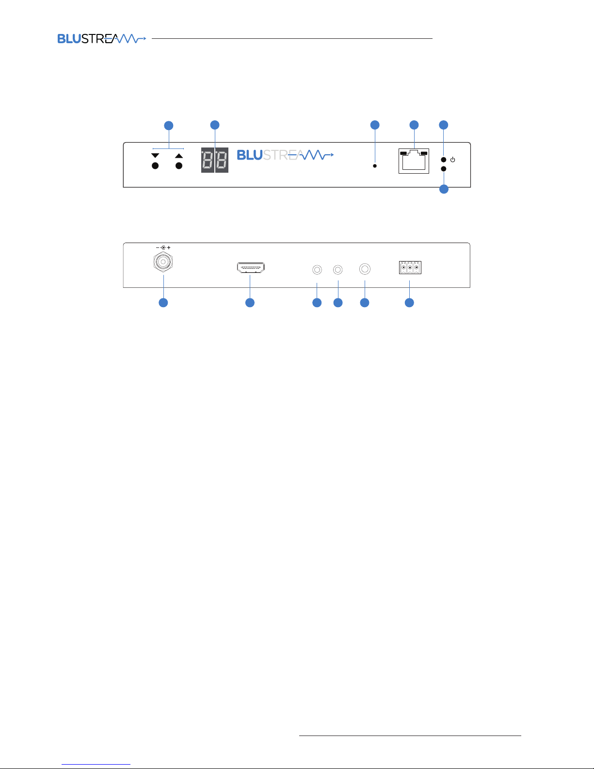
IP100UHD-TX Front Panel
Rx
Tx
Line I N
HDMI IN
DC IN
IRIR
RX
TX
RS-232
24 56V~
Gnd
TX
121110987
Link
PoE PWR
CH
CH Select
Lan
IP100UHD-TXMULTICAST UHD
2
1
3 4 5
6
1 Channel select UP/Down - Used to setup IP100UHD-TX manually and apply ‘Programming mode’
2 Channel status window - Displays product information
3 Reset button - Press and hold for 5 seconds to factory reset the product
4 LAN Connection (PoE) - Connect to Layer 3 Managed switch for HDMI video distribution
5 Power LED indicator
6 Link LED indicator - Solid status light indicates a stable connection to the network switch
7 Power port – Use 24-56V 1A DC adaptor (sold separately) if not using a PoE network switch
8 HDMI input – Connect to a HDMI source
9 IR RX (IR input) – 3.5mm stereo jack. Transmits IR to any IP100UHD-RX receiver currently viewing the IP100UHD-TX.
Please use supplied Blustream IRR 5V IR Receiver. When using the Blustream IRCAB cable (optional) ensure cable
direction is correct
q IR TX - (IR output) - 3.5mm mono jack – Routed IR from any IP100UHD-RX (zone output) allowing source control.
Use supplied Blustream 5V IR emitters
w L/R Analogue audio line input - Used to embed Analogue audio onto HDMI signal
e Assignable bi-directional RS-232 ports – Connect to third party control device to extend RS-232 commands to any/
multiple IP100UHD Multicast product RS-232 port
IP100UHD-TX Rear Panel
Panel Description - IP100UHD-TX Transmitter
MULTICAST USER MANUAL
06
www.blustream.co.uk
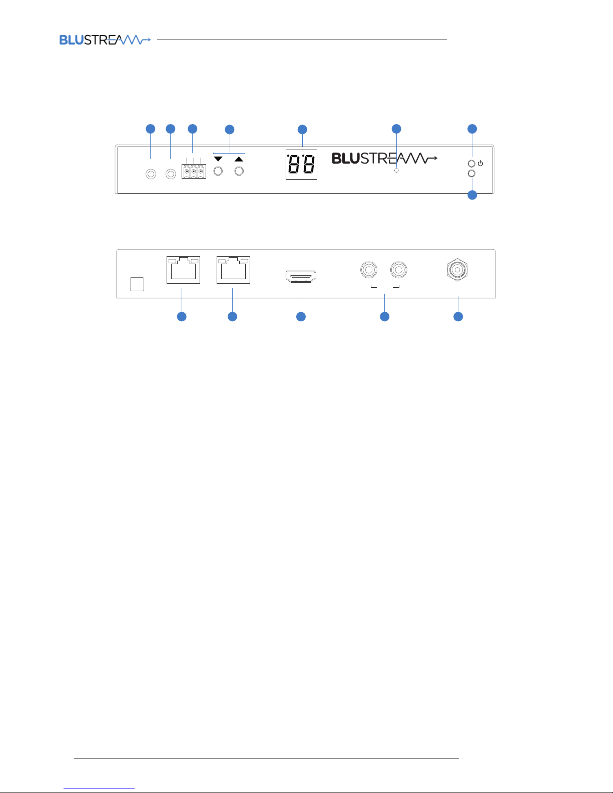
IP100UHD-RX Front Panel
Link
PoE PWR
CH
CH Select
Lan
IP100UHD-TXMULTICAST UHD
Rx
Tx
Line IN
HDMI IN
DC IN
IRIR
RX
TX
RS-232
24 56V~
Gnd
TX
L/R
HDMI Out
RX
DC IN
24 56V~
Link
RXTX
CH Select
IR IR
Rx
Tx
Gnd
RS-232
CH
IP100UHD-RXMULTICAST UHD
1110987
1 IR TX - (IR output) - 3.5mm mono jack – Routed IR to current selected IP100UHD-TX (Source Transmitter). Use
supplied Blustream 5V IR emitters
2 IR RX (IR input) – 3.5mm stereo jack. Transmits IR to currently selected IP100UHD-TX transmitter allowing routed
IR control of sources. Please use supplied Blustream IRR 5V IR Receiver. When using the Blustream IRCAB cable
(optional) ensure cable direction is correct
3 Assignable bi-directional RS-232 port – Connect to third party control device to extend RS-232 commands to any/
multiple IP100UHD Multicast product RS-232 port
4 Channel select UP/Down - Used to scroll through sources (IP100UHD-TX), setup IP100UHD-RX manually and apply
‘Programming mode’
5 Channel status window - Displays product information
6 Reset button - Press and hold for 5 seconds to factory reset the product
7 Power LED indicator
8 Link LED indicator - Solid status light indicates a stable connection to the network switch
9 HDMI output – Connect to a HDMI display
q L/R Analogue audio line output - Used to breakout Analogue audio from HDMI signal
NOTE: Source input must be PCM 2ch audio for analogue audio outputs to work. The Multicast products do not
down-mix 5.1ch audio signals
Audio outputs are fixed line level output
w Power port – Use 24-56V 1A DC adaptor (sold separately) if not using a PoE network switch
IP100UHD-RX Rear Panel
Panel Description - IP100UHD-RX Receiver
Link
PoE PWR
CH
CH Select
Lan
IP100UHD-TXMULTICAST UHD
Rx
Tx
Line IN
HDMI IN
DC IN
IRIR
RX
TX
RS-232
24 56V~
Gnd
TX
Link
RXTX
CH Select
IR IR
Rx
Tx
Gnd
RS-232
CH
IP100UHD-RXMULTICAST UHD
3
4
6 7
8
21
5
MULTICAST USER MANUAL
07
contact support@blustream.co.uk / support@blustream.com.au
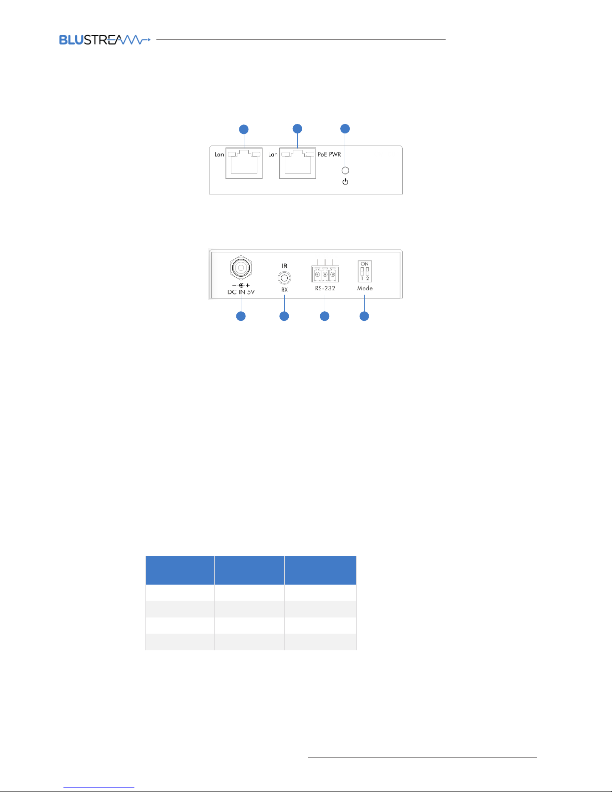
CM100 Front Panel
7654
1 Control LAN port - Connect to existing network that your third party control system resides on. The Control LAN
port is used for Telnet/IP control of the Multicast system
2 Multicast Video LAN port - Connect to the layer 3 network switch that the Blustream Multicast components are
connected to
3 Power LED indicator
4 Power port – Use 5V 1A DC adaptor (sold separately) if not using a PoE network switch
5 IR RX (IR input) – 3.5mm stereo jack. Connect to third party control system if you are using IR as your method of
controlling the Multicast system. Please use supplied Blustream IRR 5V IR Receiver. When using the Blustream
IRCAB cable (optional) ensure cable direction is correct.
Note: Only basic switching commands are available when using IR as a method of control. Advance Multicast
features are only available using Telnet/IP and RS-232
6 RS-232 control port – Connect to a third party control device for control of the Multicast system using RS-232
7 Mode dip-switches - Used for adjusting the RS-232 control port baudrate settings as per the chart below.
Note - If changing the Baudrate settings of the CM100 you must power cycle the unit for these to update
CM100 Rear Panel
Panel Description - CM100 Control Module
21 3
CONTROL LAN VIDEO LAN
Data Bit: 8-bit
Parity: None
Stop Bit: 1-bit
Flow Control: None
Baudrate
Mode Dip-
Switch 1
Mode Dip-
Switch 2
9600 Down Down
19200 Down Up
57600 Up Down
115200 Up Up

MULTICAST USER MANUAL
08
www.blustream.co.uk
The Blustream Multicast system distributes HDMI video over layer 3 managed network hardware. It is advised that
Blustream Multicast products are connected on an independent network switch to prevent interference or drop in
signal performance due to other network products.
Blustream Multicast products are not limited to certain brands of network hardware but should you be using a network
switch that Blustream have not tested or written instructions for you will need to make sure it supports the following
network features:
Multicast
Multicast (one-to-many or many-to-many distribution) is group communication where information is addressed to a
group of network devices simultaneously (Blustream IP100UHD-RX Receivers).
Instant Leave/Fast Leave/Immediate Leave
This feature is a feature associated with Multicast and means that as soon as an active connection is no longer required
(the link between Transmitter and Receiver) the Multicast group and flow of track is stopped instantly. This prevents
unnecessary flow of network traic on the network switch.
IGMP Snooping
IGMP snooping is the process of listening to Internet Group Management Protocol (IGMP) network traic. The feature
allows a network switch to listen in on the IGMP conversation between hosts and routers (Transmitters and Receivers).
By listening to this flow of traic the switch maintains a map of which links need which IP multicast streams. Multicasts
may be filtered from the links which do not need them and thus controls which ports receive specific multicast traic.
Jumbo Frames/Jumbo Packets/MTU (Maximum Transmission Unit)
Jumbo frames are Ethernet frames with more than 1500 bytes of payload. Conventionally, jumbo frames can carry
up to 9000 bytes of payload, but variations exist and some care must be taken using the term. Many Gigabit Ethernet
switches can support jumbo frames.
Please Note:
Blustream have worked with many network switch providers to create setup guides and saved configuration files to
help configure the products to work with the Multicast hardware. These configuration files can be found online at the
following link and selecting the 'Drivers & Protocols' button on the website:
www.blustream.co.uk/ip100uhd
HDMI Over IP Network Configuration

MULTICAST USER MANUAL
09
contact support@blustream.co.uk / support@blustream.com.au
Understanding Product Status Lights
Transmitter Audio Embedding
Rx
Tx
Line I N
HDMI IN
DC IN
IRIR
RX
TX
RS-232
24 56V~
Gnd
TX
1
Receiver Audio Breakout
Link
PoE PWR
CH
CH Select
Lan
IP100UHD-TXMULTICAST UHD
Rx
Tx
Line IN
HDMI IN
DC IN
IRIR
RX
TX
RS-232
24 56V~
Gnd
TX
L/R
HDMI Out
RX
DC IN
24 56V~
Link
RXTX
CH Select
IR IR
Rx
Tx
Gnd
RS-232
CH
IP100UHD-RXMULTICAST UHD
2
The Multicast products have several LED lights to indicate connectivity status and help diagnose connection problems.
Link
PoE PWR
CH
CH Select
Lan
IP100UHD-TXMULTICAST UHD
1 32
4
Multicast Status Lights
1 LAN PoE status light - Solid Orange indicates PoE from the network switch powering the Multicast product
2 LAN status light - Solid Green indicates active network connection
3 Power status light - O = No power, Flashing = Product booting, On = Power on
4 Link status light - O = No connection to network, Flashing = not connected to any device (another Multicast
product or network switch), On = Connected to Multicast device or network switch
Audio Connections
1 Analogue L/R Line Level audio input
The Analogue line level input can be used to replace the original HDMI audio of the source connected to the
Multicast Transmitter with Analogue L/R 2ch line level audio. The embedded Analogue audio is then distributed
with the adjacent HDMI video signal throughout the Multicast system.
Switching between original HDMI audio and embedded line level analogue 2ch audio is achieved using Blustream
serial/Telnet/IP commands.
Note: It is only possible to select EITHER HDMI audio or local Analogue line input. It is not possible to distribute
both audio sources at the same time.
2 Analogue L/R Line Level audio output
The IP100UHD-RX Multicast Receiver includes audio breakout from the selected HDMI source to associated
Analogue L/R audio outputs. Extracted audio will be concurrent with the corresponding HDMI video output.
Note: The source input must be PCM 2ch audio for Analogue audio outputs to work. The Blustream Multicast
products do not down-mix Dolby Digital, DTS or 5.1ch audio signals.
MULTICAST USER MANUAL
10
www.blustream.co.uk
The Blustream Multicast system can be controlled using local IR hardware connected directly to the IP100UHD-RX
Receiver. This prevents the need for a third party control solution. Only the source selection feature is available using
local IR control through the Receiver. For advanced features such as video wall mode, audio embedding etc you will
need to use RS-232 or TCP/IP control.
Blustream have created 80 IR commands allowing source selection of up to 80 IP100UHD-TX Transmitters. For systems
larger than 80 source devices (IP100UHD-TX) we recommend the CM100 control module.
The full list of Blustream IR codes can be found at the rear of this manual on page 57 ‘IP100 Multicast Infrared Commands’
Infrared Control
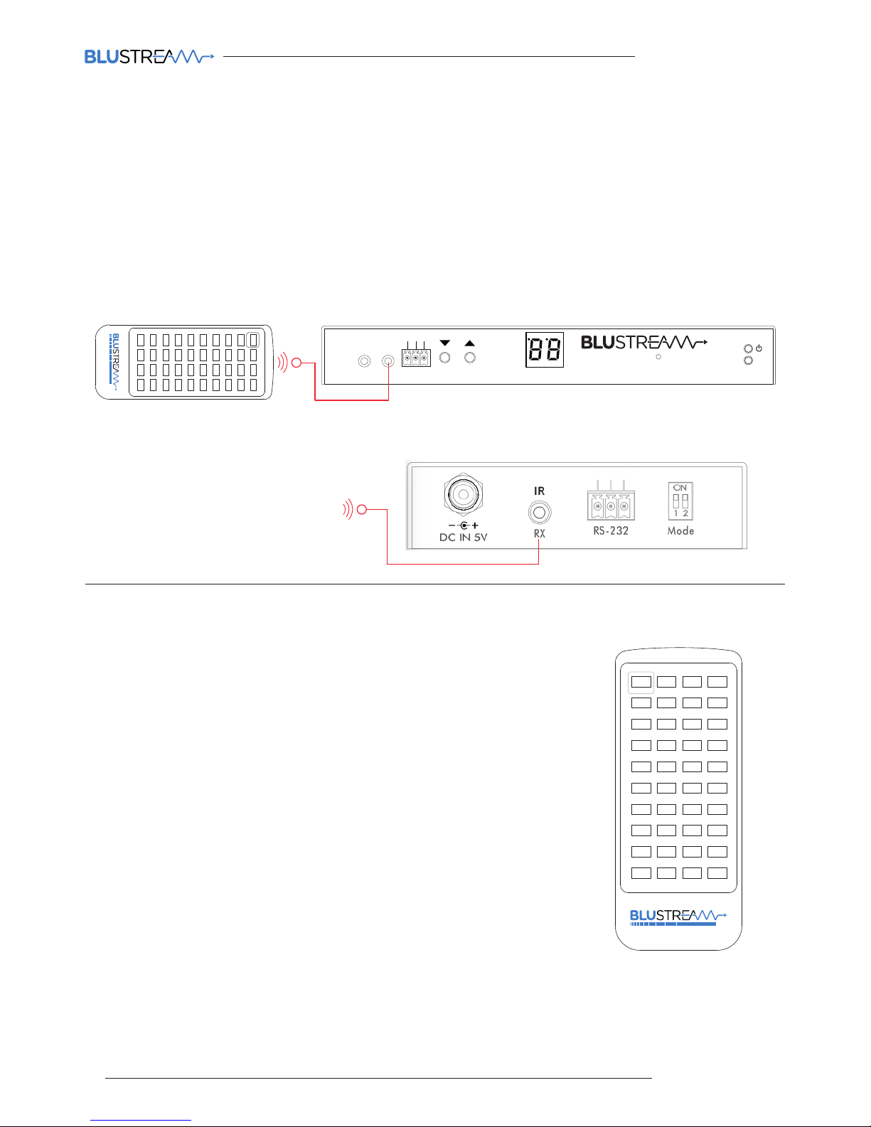
Input (Transmitter) Selection
The Blustream REM100 remote control can be used at any Blustream IP100UHD-RX
Receiver product and can select up to 80 source inputs (transmitters).
Using the remote:
Sources 1-40 are selected using the input selection buttons 1-40
Sources 41-80 are selected by first activating the ‘secondary control mode’ which
is achieved by pressing and holding source button 1 for 5 seconds. Once this mode
is active the buttons 1-40 are now selecting sources 41-80.
To return control back to source inputs 1-40 simply press and hold source button 1
for 5 seconds to revert to ‘main control mode’.
Link
RXTX
CH Select
IR IR
Rx
Tx
Gnd
RS-232
CH
IP100UHD-RXMULTICAST UHD
1 2 3 4
41 42 43 44
45 46 47 48
49 50 51 52
53 54 55 56
57 58 59 60
61 62 63 64
65 66 67 68
69 70 71 72
73 74 75 76
77 78 79 80
5 6 7 8
9 10 11 12
13 14 15 16
17 18 19 20
21 22 23 24
25 26 27 28
29 30 31 32
33 34 35 36
37 38 39 40
MULTICAST
1 2 3 4
41 42 43 44
45 46 47 48
49 50 51 52
53 54 55 56
57 58 59 60
61 62 63 64
65 66 67 68
69 70 71 72
73 74 75 76
77 78 79 80
5 6 7 8
9 10 11 12
13 14 15 16
17 18 19 20
21 22 23 24
25 26 27 28
29 30 31 32
33 34 35 36
37 38 39 40
MULTICAST
Remote Control - REM100
Link
RXTX
CH Select
IR IR
Rx
Tx
Gnd
RS-232
CH
IP100UHD-RXMULTICAST UHD
Third Party Control System
Infrared Control with REM100 and IP100UHD-RX
Infrared Control with Third Party Control System and CM100

MULTICAST USER MANUAL
11
contact support@blustream.co.uk / support@blustream.com.au
The Blustream range of Multicast products include multiple options for control and routing of IR.
IMPORTANT: Blustream Infrared products are all 5v and NOT compatible with alternative manufacturers
Infrared solutions. When using third party 12v IR control solutions please use supplied Blustream IRCAB
cable for IR conversion.
Each Blustream Multicast Transmitter and Receiver is supplied with both an IR Receiver and Emitter, details below:
IR Emitter - IR1 & IR2 (IR2 sold separately)
Blustream 5V IR Emitter designed for discrete IR control
of hardware
IR Receiver - IRR
Blustream 5V IR receiver to receive IR signal and
distribute through Blustream products
IR Control Cable - IRCAB (optional)
Blustream IR Control cable 3.5mm Mono to 3.5mm
Stereo for linking third party control solutions to
Blustream products.
Compatible with 12v IR third party products.
Note: Cable is directional as indicated
Infrared 3.5mm Pin-Out
IR Emitter - Mono 3.5mm
IR Receiver - Stereo 3.5mm
Infrared Distribution
Signal
5V
Ground
Signal
Ground
MULTICAST USER MANUAL
12
www.blustream.co.uk
Note: The IR pass-through features are available in all modes of Multicast use (matrix mode, video-wall, one-to-one
and one-to-many)
Connections:
The IR receiver is connected to the IR RX socket on the IP100UHD-RX.
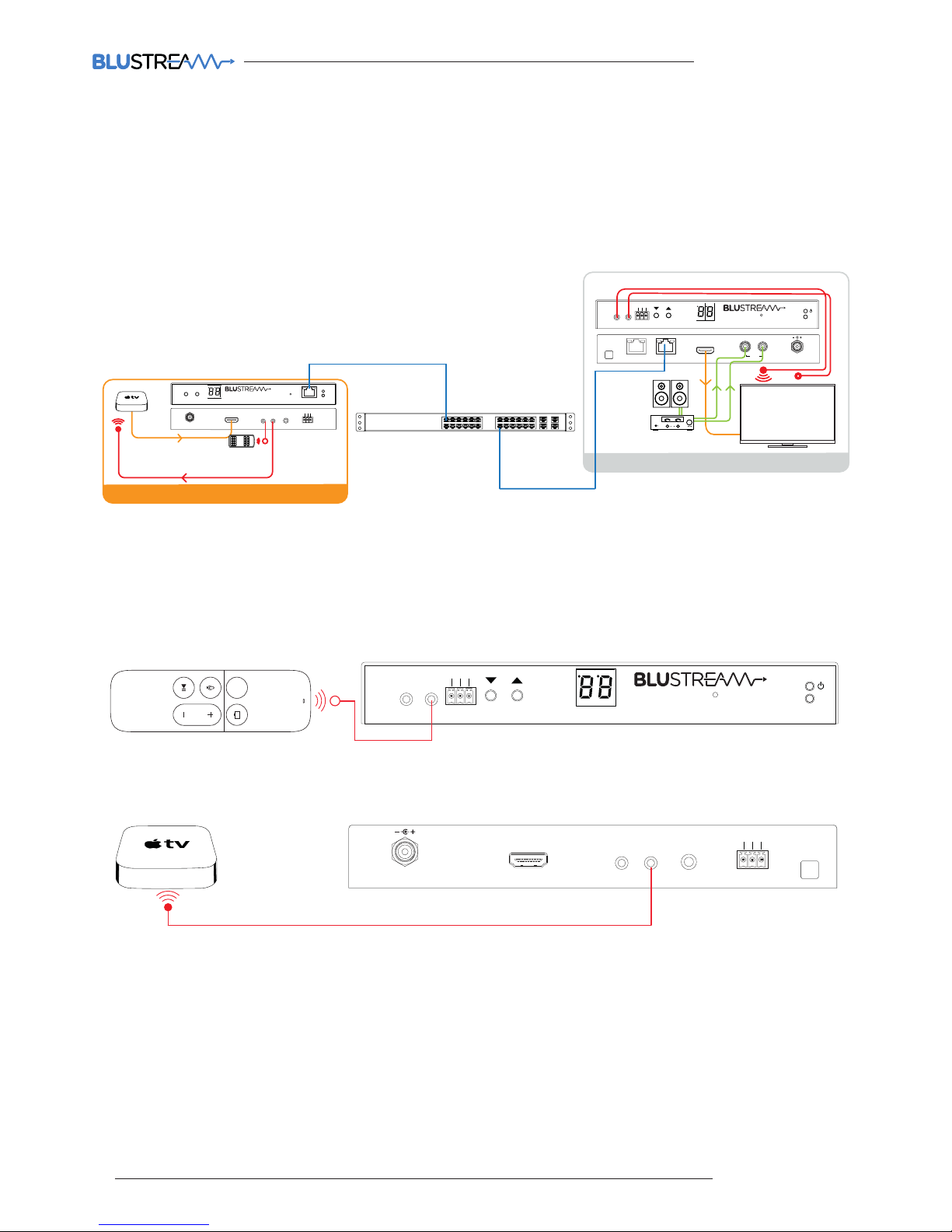
Infrared Pass-Through (Source Control)
The Multicast products feature Infrared pass-through allowing users to use original source remote controls in the field
and control those sources located in another area.
The IR signal is routed to only the current source that is selected meaning that individual source control can be
achieved with installations consisting of multiple source equipment of the same type, I.E - Multiple Satellite boxes of
the same make and model.
Link
RXTX
CH Select
IR IR
Rx
Tx
Gnd
RS-232
CH
IP100UHD-RXMULTICAST UHD
MENU
Rx
Tx
Line IN
HDMI IN
DC IN
IRIR
RX
TX
RS-232
24 56V~
Gnd
TX
Rx
Tx
Line IN
HDMIIN
DCIN
IRIR
RS-232
24 56V~
Gnd
TX
PoEPWR
CH
CHSelect
Lan
IP100UHD-TXMULTICAST UHD
TX
SOURCE 01
RX
Link
RXTX
CHSelect
Rx
Tx
Gnd
RS-232
CH
IP100UHD-RXMULTICAST UHD
L/R
RX
DCIN
24 56V~
HDMI Out
IRIR
ZONE 01
The IR emitter is connected to the IR TX socket on the IP100UHD-TX and located on the IR receiver window of your
source device.
Link
MULTICAST USER MANUAL
13
contact support@blustream.co.uk / support@blustream.com.au
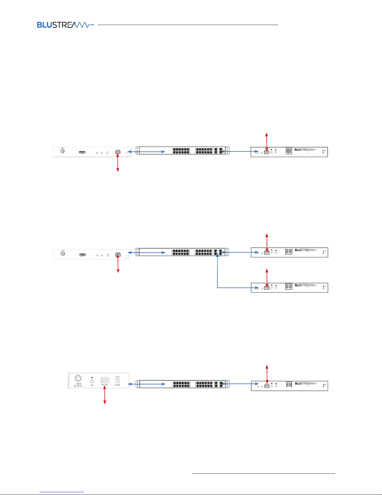
RS-232 (Serial) Bi-Directional Pass-Through
The Multicast products feature bi-directional RS-232 pass-through for control of products using serial commands.
There are multiple methods for distribution of RS-232 using the Blustream Multicast solution which include:-
Note: Only one method of RS-232 pass-through can be used at the same time. It is not possible to mix dierent
methods of RS-232 control.
1) 1-to-1 routed RS-232
A link is programmed that creates an open connection between ANY Multicast product in the system (Transmitters or
Receivers). Once established the RS-232 commands can be sent in either direction between products.
Multiple links can be created between Multicast products for additional independent product control.
2) 1-to-many routed RS-232
A link is programmed that creates an open connection between MULTIPLE Multicast products in the system
(Transmitters or Receivers). Once established the RS-232 commands can be sent in either direction between products
but allows a single command to be sent to multiple products at the same time I.E - All displays powered on.
3) Guest Mode - Telnet/IP conversion to RS-232
This method of control converts a Telnet/IP control command into an RS-232 command. A link is programmed that
creates an open connection between a CM100 control module and any IP100UHD-TX or RX (Transmitters or Receivers)
product in the system. Telnet/IP commands are sent into the CM100 from a third party control solution. This is then
converted into an RS-232/serial command for control of third party products.
Link
PoEPWR
CH
CHSelect
Lan
IP100UHD-TXMULTICAST UHD
Rx
Tx
LineIN
HDMIIN
DCIN
IRIR
RX
TX
RS-232
24 56V~
Gnd
TX
Link
RXTX
CHSelect
IR IR
Rx
Tx
Gnd
RS-232
CH
IP100UHD-RXMULTICAST UHD
Link
PoEPWR
CH
CHSelect
Lan
IP100UHD-TXMULTICAST UHD
Rx
Tx
LineIN
HDMIIN
DCIN
IRIR
RX
TX
RS-232
24 56V~
Gnd
TX
Third party control system I.E - Control4, Elan, RTI etc
Serial controlled display
RS-232
RS-232
Link
PoEPWR
CH
CHSelect
Lan
IP100UHD-TXMULTICAST UHD
Rx
Tx
LineIN
HDMIIN
DCIN
IRIR
RX
TX
RS-232
24 56V~
Gnd
TX
Link
RXTX
CHSelect
IR IR
Rx
Tx
Gnd
RS-232
CH
IP100UHD-RXMULTICAST UHD
Link
PoEPWR
CH
CHSelect
Lan
IP100UHD-TXMULTICAST UHD
Rx
Tx
LineIN
HDMIIN
DCIN
IRIR
RX
TX
RS-232
24 56V~
Gnd
TX
Link
RXTX
CHSelect
IR IR
Rx
Tx
Gnd
RS-232
CH
IP100UHD-RXMULTICAST UHD
Link
PoEPWR
CH
CHSelect
Lan
IP100UHD-TXMULTICAST UHD
Rx
Tx
LineIN
HDMIIN
DCIN
IRIR
RX
TX
RS-232
24 56V~
Gnd
TX
Third party control system I.E - Control4, Elan, RTI etc
Serial controlled display
RS-232
RS-232
Serial controlled display
RS-232
Link
PoEPWR
CH
CHSelect
Lan
IP100UHD-TXMULTICAST UHD
Rx
Tx
LineIN
HDMIIN
DCIN
IRIR
RX
TX
RS-232
24 56V~
Gnd
TX
Link
RXTX
CHSelect
IR IR
Rx
Tx
Gnd
RS-232
CH
IP100UHD-RXMULTICAST UHD
Third party control system I.E - Control4, Elan, RTI etc
Serial controlled display
RS-232
or
TCP/IP
RS-232
MULTICAST USER MANUAL
14
www.blustream.co.uk
Guest Mode - Telnet/IP Conversion To RS-232
The Multicast products feature bi-directional RS-232 pass-through for control of products using serial commands from
the CM100. This is also known as RS-232 Guest Mode. To utilise this you must first enable Guest Mode as follows.
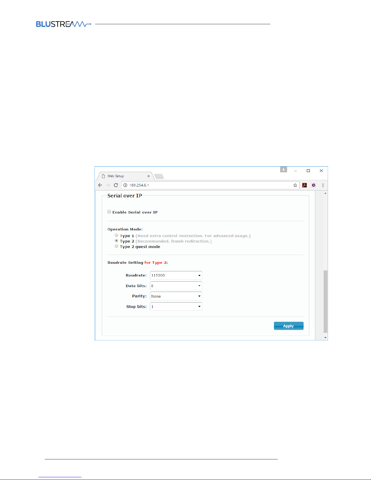
RS-232 Guest Mode Set Up
1) Guest Mode must be enabled in each IP100UHD-TX and RX unit in order to use this functionality.
Connect to the Web GUI of the IP100UHD-TX or RX that you wish to enable guest mode for by entering its IP
Address in your web browser and navigate to the Functions' tab.
For example: 169.254.6.1 is the default IP address for RX ID 1.
2) Check the checkbox for 'Enable Serial over IP'
3) Select the checkbox for 'Type 2 guest mode'
Ensure all Baudrate settings are correct for the product that you wish to control.
RS-232 Guest Mode Communication
1) To open a Guest Mode connection between the CM100 and an IP100UHD-TX or RX unit you must send the
following command via IP or RS-232:
INxxxGUEST Connect to TX xxx in Guest mode from the CM100
OUTxxxGUEST Connect to RX xxx in Guest mode from the CM100
Example:- Transmitter one is ID 001, meaning 'IN010GUEST' will allow bi-directional Serial or TCP/IP
commands between CM100 and Transmitter 001.
2) Once a connection is established, any characters that you send from the CM100 will be transmitetd to the
IP100UHD-TX or RX that you have connected with, and vice versa.
3) To close the connection you must send the escape command 0x02 (02 in Hex).
If using telnet you can also close the connection by pressing CTRL + B.
MULTICAST USER MANUAL
15
contact support@blustream.co.uk / support@blustream.com.au
The Blustream Multicast system can be configured without the need of a computer, allowing basic setup options such
as addressing of products (IP configuration), EDID setup and scaler output setup.
Manual configuration does not require the product to be connected to a network switch in order to be setup, they only
require the units to be powered either by local power supply (24-54V 1A) or by a PoE switch/power injector. This means
total configuration can easily be achieved osite without any network hardware.
Note: Advanced features such as video walls cannot be setup via manual configuration, and requires the PC soware.
Configuring the IP100UHD-TX
1) Power the Multicast product - To configure the Multicast Transmitter first connect the product to a power supply
(local or PoE network) and wait for the product to boot up. The front panel LED display will rotate whilst booting and
display a 2 digit number when complete.
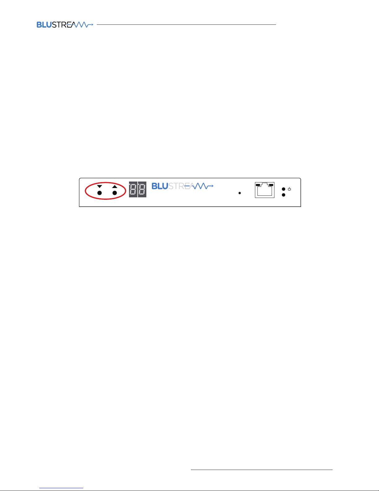
2) Put the Multicast product into 'Local Configuration' mode - Once the product is powered press both the 'UP'
and 'DOWN' channel buttons on the front panel at the same time for 6 seconds to enter 'Local configuration' mode.
You will know that the IP100UHD-TX is in this mode as the LCD front display of the product will show 'LC'.
3) Assign the Transmitter ID (IP address) - Once the product is local configuration mode the display will begin to
flash with a lowercase 't' to indicate that you are about to assign the transmitter identity. The identity will also be the IP
address that is automatically assigned so it is of upmost importance that you do not assign any 2 Multicast Transmitter
products with the same ID/IP address.
The first ID you should assign is ID1 = 169.254.3.1 (IP address 1)
The second ID you should assign is ID2 = 169.254.3.2 (IP address 2)
And so on....
Once you have selected the ID number press both Channel 'UP' and 'DOWN' buttons at the same time to move on to
setting the EDID.
4) Set the EDID - Once the product is in EDID configuration mode the display will begin to flash with a lowercase
'e' to indicate that you are about to assign an EDID value. Use the 'UP' and 'DOWN' arrows to select the EDID setting
required. A full list of EDID settings can be found on page 16 'EDID Control'.
For example: If the display shows '00' the EDID will be 1080P 2CH.
Once you have selected the EDID required press both Channel 'UP' and 'DOWN' buttons at the same time to finalise
the setup. The Multicast product will reboot with the new configuration settings applied.
5) Configuring the IP100UHD-RX
Configuring the identity of the IP100UHD-RX Receiver is the same steps (steps 1 to 3) as shown above for the configuration of the IP100UHD-TX. When ID has been assigned the Receivers have the following IP addresses:
The first Receiver ID assigned is ID1 = 169.254.6.1 (IP address 1)
The second Receiver ID is ID2 = 169.254.6.2 (IP address 2)
And so on....
6) Set the Video Scaler of the Receiver - Once the product ID has been configured the display will begin to flash with
a lowercase 's' to indicate that you are about to set the scaler output. Use the 'UP' and 'DOWN' arrows to select the
scaler setting required. A full list of scaler settings can be found on page 17 'Scaler Output Control'.
For example: If the display shows '10' the Scaler output will be 4K 30Hz.
Once you have selected the Scaler output required press both Channel 'UP' and 'DOWN' buttons at the same time to
finalise the setup. The Multicast product will reboot with the new configuration settings applied.
Manual Configuration of Multicast Products
Link
PoE PWR
CH
CH Select
Lan
IP100UHD-TXMULTICAST UHD

MULTICAST USER MANUAL
16
www.blustream.co.uk
EDID Control
EDID (Extended Display Identification Data) is a data structure that is used between a display and a source. This data
is used by the source to find out what audio and video resolutions are supported by the display device. From this
information the source will discover what the best audio and video resolutions need to be outputted.
In a normal Matrix based system issues do arise when multiple displays or video matrix switching is introduced
because of the increased number of variables.
In the Blustream Multicast system each source device only communicates with a single Blustream IP100UHD-TX
Transmitter meaning there is only a single EDID handshake. As each Blustream Multicast IP100UHD-RX Receiver has its
own in-built video scaler, it is advised that the source EDID is set to output the best video signal possible as this can be
down-scaled if required at each IP100UHD-RX Receiver.
Configuration of Multicast EDID settings can be achieved in several ways:-
1) During the manual configuration of the IP100UHD-TX Transmitter
2) Using the Blustream Multicast PC configuration soware
3) Using the Multicast Web GUI interface
4) Using RS-232 commands via Blustream CM100
When configuring the EDID during manual setup or using RS-232 commands the following table indicates EDID values:
EDID MULTICAST TRANSMITTER EDID SETTINGS
00 HDMI 1080p@60Hz, Audio 2CH PCM
01 HDMI 1080p@60Hz, Audio 5.1CH PCM/DTS/DOLBY
02 HDMI 1080p@60Hz, Audio 7.1CH PCM/DTS/DOLBY/HD
03 HDMI 1080i@60Hz, Audio 2CH PCM
04 HDMI 1080i@60Hz, Audio 5.1CH PCM/DTS/DOLBY
05 HDMI 1080i@60Hz, Audio 7.1CH PCM/DTS/DOLBY/HD
06 HDMI 1080p@60Hz/3D, Audio 2CH PCM
07 HDMI 1080p@60Hz/3D, Audio 5.1CH PCM/DTS/DOLBY
08 HDMI 1080p@60Hz/3D, Audio 7.1CH PCM/DTS/DOLBY/HD
09 HDMI 4K2K 4:4:4, Audio 2CH PCM
10 HDMI 4K2K 4:4:4, Audio 5.1CH PCM/DTS/DOLBY
11 HDMI 4K2K 4:4:4, Audio 7.1CH PCM/DTS/DOLBY/HD
12 DVI 1280x1024@60Hz, Audio None
13 DVI 1920x1080@60Hz, Audio None
14 DVI 1920x1200@60Hz, Audio None
15 Default EDID (Pass-through)
16
4K2K 4:2:0 @ 60Hz, Audio 2CH PCM
17
4K2K 4:2:0 @ 60Hz, Audio 5.1CH PCM/DTS/DOLBY
18
4K2K 4:2:0 @ 60Hz, Audio 7.1CH PCM/DTS/DOLBY/HD
Note: The Blustream Multicast products do not down-mix Dolby Digital, DTS or 5.1ch audio signals. Should
your end-points (displays) only support 2CH PCM you must set the EDID value to match audio formats
supported throughout the system.

MULTICAST USER MANUAL
17
contact support@blustream.co.uk / support@blustream.com.au
The Blustream Multicast Receiver has an in-built video scaler which can both up-scale and downscale video signals
allowing the best picture quality possible at each display.
Configuration of Multicast Scaler settings can be achieved in several ways:-
1 During the manual configuration of the Multicast Receiver
2 Using the Blustream Multicast PC configuration soware
3 Using the Multicast Web GUI interface
4 Using RS-232 commands via the Blustream CM100
When configuring the Scaling during manual setup or using RS-232 commands the following table indicates Scaler
settings.
Scaler Output Control
SCALER MULTICAST RECEIVER SCALER SETTINGS
00 Passthrough
01 HDMI 1080p@50Hz
02 HDMI 1080p@60Hz
03 HDMI 720P@60Hz
04 HDMI 720P@50Hz
05 HDMI 1280 x 1024@60Hz
06 HDMI 1024 x 768@60Hz
07 HDMI 1360 x 768@60Hz
08 HDMI 1440 x 900@60Hz
09 HDMI 1680 x 1050@60Hz
10 HDMI 4K2K@30Hz
11 HDMI 4K2K@24Hz

MULTICAST USER MANUAL
18
www.blustream.co.uk
The following pages will review the Blustream Multicast PC program and Web GUI interface, giving the installer the
knowledge to completely configure a full Blustream HDMI over IP system.
Prior to running the Blustream Multicast PC configuration soware it is important that you have the following hardware
available:
• PC with active LAN Network connection
• CAT network cables - straight connection
• Layer 3 managed network switch (POE) OR 24-56V DC power supply to power the units locally
Multicast PC Program
Supporting Documentation & Downloads
The relevant supporting for the Blustream Multicast products can be found on the Blustream website:
www.blustream.co.uk/ip100uhd
Click on the ‘Drivers & Protocols’ download button located on the individual Multicast product webpage:
This link will give access to the following information / documentation:
- IP100UHDTX/RX Firmware - this will always be the most current version of firmware available
- CM100 Documentation - firmware, 3rd party control drivers
- Multicast PC Program download (.exe format)
- Multicast Documentation
- Network Switch Instructions (Cisco, Luxul, etc)

MULTICAST USER MANUAL
19
contact support@blustream.co.uk / support@blustream.com.au
IP100UHD Firmware Update
Prior to commencing installation of your Multicast system, it is important that the Blustream IP100UHD-TX/RX products
are loaded with the latest firmware. The latest firmware can be found on the Blustream Website:
www.blustream.co.uk/ip100uhd, using the Drivers & Protocols download button - see page 18 of this manual.
Updating the Blustream Multicast product firmware can be acheived in 2 ways:
1) Using the ‘Firmware Update’ feature in the ‘Advanced’ section of the PC program. This is the easiest method.
2) Using the products own Web GUI interface.
The below instructions are a step-by-step guide to upgrading the firmware in each Multicast product for new units
that are yet to be configured. The firmware process must be completed one-by-one due to all products being shipped
with the same standard factory set default IP address. Failure to do so may end up corrupting the firmware in the
products, resulting in product failure.
Prior to upgrading the firmware in Blustream Multicast products using either of the above methods it is important you
first complete the below instructions.
1) In order to communicate with the Blustream Multicast hardware your computer will need to be physically
connected to either:-
a) A PoE network switch using an Ethernet network cable which is in turn connected to the Blustream
IP100UHD-TX/RX product
b) The Blustream IP100UHD product directly which must be powered locally using a 24-56V DC power supply
(sold separately)
2) IMPORTANT: Prior to connecting the Blustream Multicast IP100 product to your network switch/local
power supply, it is recommended that the product is forced into ‘firmware update mode’. Firmware Upgrade
Mode stops the Multicast products from streaming video and activates a status for only updating product firmware.
To activate Firmware Update Mode:
a) Press both the ‘CH SELECT UP’ and ‘CH SELECT DOWN’ buttons located on the product front panel at the same
time. Whilst holding these buttons down...
b) Insert the PoE network cable or local 24-56V DC power supply
c) Do not release the buttons until the product shows ‘PG’ in the status window on the front panel
Product firmware can be updated without ‘Firmware Update Mode’ but you must stop any streaming service to/from
the product before you proceed with the firmware upgrade. Failure to do so may result in loss of firmware transmission
packets due to un-necessary traic on the network.
3) In order to be able to communicate with the Blustream IP products your computer must also be in the same IP
range as the Blustream IP100UHD-TX/RX default IP address. If you are unsure how to update your computer IP range
follow the ‘Changing your computer IP address’ instructions at the rear of this guide.
The default IP address of all new Multicast IP100UHD-TX/RX is:
169.254.100.254
MULTICAST USER MANUAL
20
www.blustream.co.uk
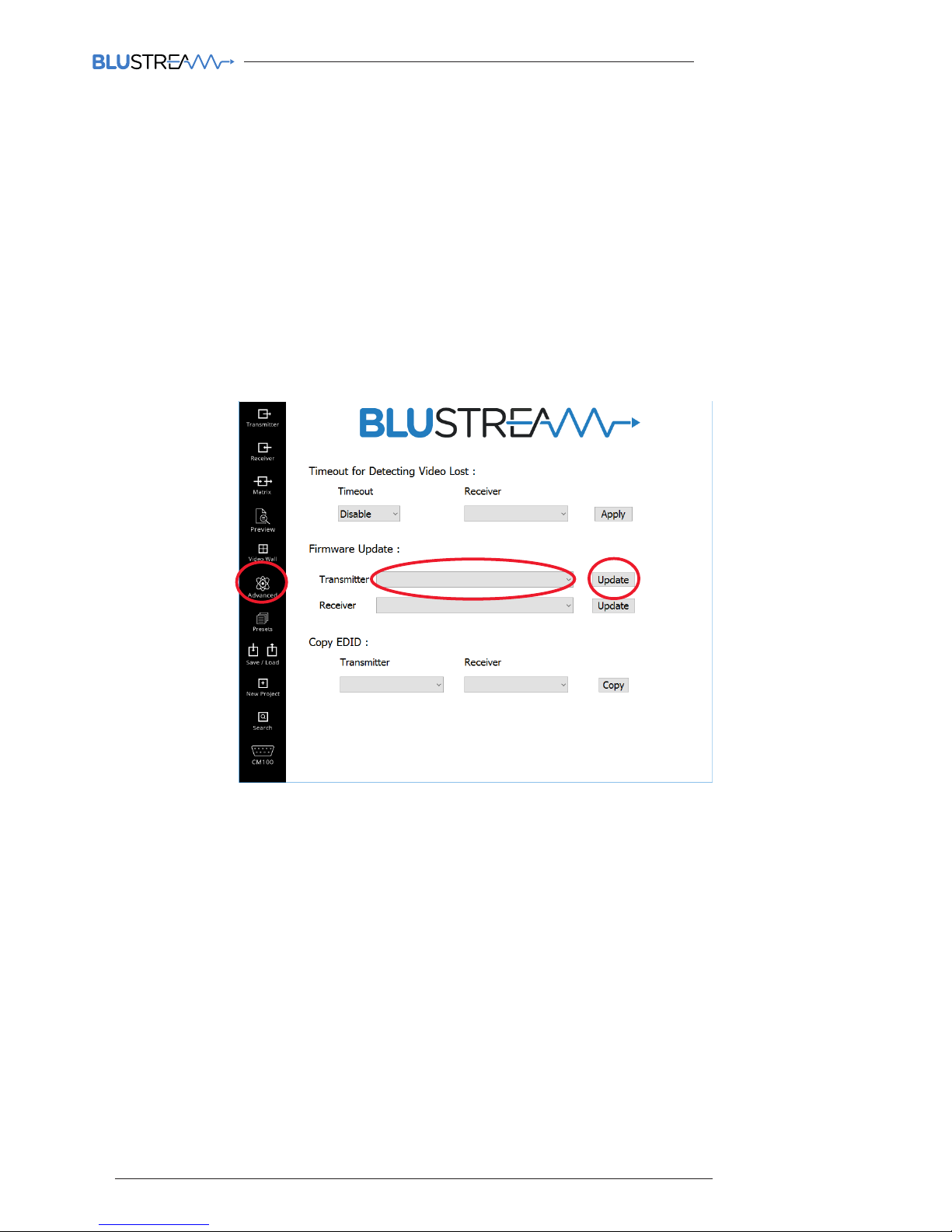
To update the firmware in either of the Transmitter or Receiver Multicast products using the Blustream PC program
please follow the below steps:
1) Open the Blustream PC Program (see page 18 for instructions of how to download this program)
2) Select the ‘ADVANCED’ tab in the side menu. In the following screen you will see the ‘Firmware Update’
option on the Advanced settings page
3) Select the product you wish to update (Transmitter or Receiver) from the drop-down box. If the product is a
new default unit select
‘New Product - Default IP 169.254.100.254’
4) Click the corresponding ‘Update’ button
A warning window will open and request that the product is put into Firmware Update Mode - see page 19
5) Download the most recent IP100UHD-TX or -RX firmware from the Blustreasm website.
Click ‘Browse’ and open the folder in which you have saved the Blustream IP100UHD-TX/RX firmware files.
6) Select the required ‘Transmitter.BIN’ or ‘Receiver.BIN’ file
7) Click ‘Upload’ which will begin the firmware upgrade process
8) Once the upgrade has completed please disconnect the network cable/power and re-connect to reboot the
product. The Transmitter/Receiver display will no longer display ‘PG’ when complete.
Please note:
DO NOT unplug the power or network connection to the IP100UHD-TX/RX as this may result in failure to
upgrade firmware, which may lead to possible failure of the unit.
The firmware upgrade process may take several minutes. Do not connect any other Blustream product that
has the same IP address during this time.
IP100UHD Firmware Update via PC Program

MULTICAST USER MANUAL
21
contact support@blustream.co.uk / support@blustream.com.au
When you first run the Blustream PC Wizard you will see multiple options in the side menu for configuration and
control of the Multicast system.
PC Program Main Menu Overview
Transmitter - page shows a summary of all IP100UHD-TX (Transmitters) installed, with
options for EDID management, checking FW version, updating settings, adding new
transmitters, replacing or rebooting products etc.
Receiver - page shows a summary of all IP100UHD-RX (Receivers) installed, with options
for resolution output (HDR and scaling), function (video wall mode or matrix), updating
settings, adding new receivers, replacing or rebooting products etc.
Matrix - this page is used for system testing and includes a matrix switching control of
any installed IP100 Transmitter and Receiver
Video Wall - page is used for the set-up, configuration and control of IP100UHD
receivers to create a video wall array of up to a size of 16x16, including: bezel & gap
compensation, monitor position layout, stretch / fit, and screen rotation
Advanced - page contains advanced settings for the Multicast products including
firmware upgrading of transmitters or receivers and time out for video lost detection
Preset - create and recall advance presets, allowing a single button recall of custom
system setup (8 presets maximum)
Save / Load - used to save or load system configuration files
Search - find all active Multicast products installed if installer does not have the saved
system file
New Project - used to configure a new Blustream Multicast system
CM100 - allows you to update firmware and set the IP Address of a CM100 if connected
to the Multicast system
Preview - this page is used for system testing and includes a video preview of any
installed IP100 Transmitter and Receiver
MULTICAST USER MANUAL
22
www.blustream.co.uk
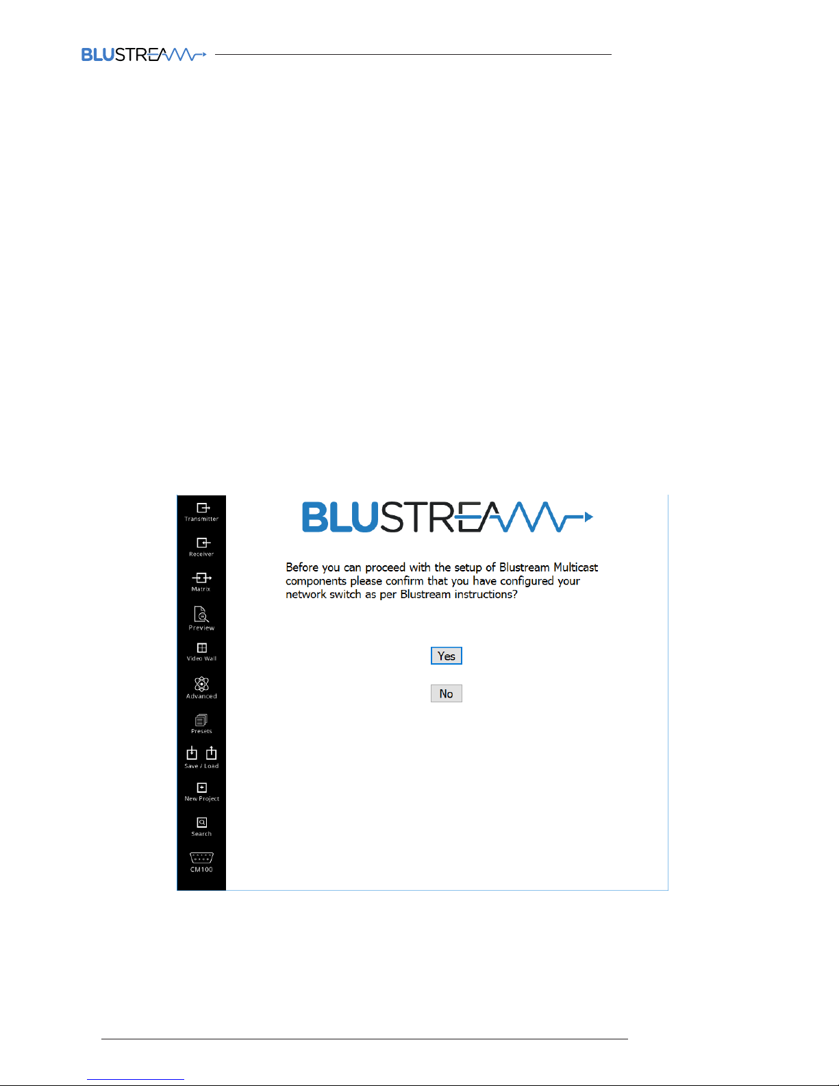
The Blustream PC Program includes a wizard for configuring all components of the Multicast system. It has been
designed to include a simple step-by-step tutorial that will guide you through the setup procedure, resulting in a
system in which all components are assigned a name and IP address ready for basic system use.
It is important to follow the wizard instructions. Failure to do so will result in incorrectly configured Multicast products.
Please see below summary of the setup process:-
1) Connecting your PC to the network switch/Multicast product
In order to configure the Blustream Multicast products your PC must first be physically connected to the products, this
can be acheived by:
a) A PoE network switch using a Ethernet network cable which is in turn connected to the Blustream
IP100UHD-TX/RX products
b) Connected directly to the Blustream IP100UHD product which must be powered locally using a 24-56V DC
power supply
In order to be able to communicate with the Blustream IP products your computer must also be in the
same IP range as the Blustream IP100UHD-TX/RX default IP address. If you are unsure how to update your
computer IP range follow the ‘Changing your computer IP address’ instructions at the rear of this guide.
New Project Configuration
Click ‘YES’ to continue with the wizard configuration
 Loading...