

Page 1
MODEL A-1600
R
Peristaltic Injection Pump
Operating Manual
5300 Business Drive
Huntington Beach, CA 92649, USA
Phone: 714-893-8529 FAX: 714-894-9492
E mail: sales@blue-white.com or techsupport@blue-white.com
Website: www.Blue-White.com
Page 2
Page 2
L
R
Thank You for purchasing the A-1600 Peristaltic Metering Pump. It is our policy
to produce, market and provide service on our products to ensure your safety
and
complete satisfaction. When installed and used in accordance with the following
instructions, the A-1600 will provide years of safe, reliable service.
For your safety the A-1600 was designed to be safe and easy to use. However,
there are limits to its operation. This instruction manual contains safety precautions, which if ignored could result in personal injury and/or property damage.
Read these instructions carefully before installing the pump. If you are not
satisfied that the unit can be safely operated, call the place of purchase for
Thank You
Blue White Industries
(714)893-8529.
LEAVE THIS INSTRUCTION MANUAL WITH INSTALLED METER!
******** SPECIFICATIONS ********
MODEL NO: MAXIMUM MAXIMUM FEED RATE
P.S.I ML/MIN OZ/MIN G.P.H G.P.D
A-1614-3N
A-1614-4
A-1614-6
A-1614-7
A-1630-3N
A-1630-4
A-1630-6
A-1630-7
A-1645-3N
A-1645-4
A-1645-6
A-1645-7
25
25
25
25
25
25
25
25
25
25
25
25
17
60
75
11
40
130
195
14
54
195
295
3
.1
.5
2.0
2.5
.3
1.3
4.4
6.5
.4
1.8
6.5
9.9
NOTE: Norprene tubing same feed rate as Tygon
6.75
5.12
.04
.26
.95
1.18
.17
.63
2.05
3.08
.22
.85
3.08
4.67
1
6
22
28
4
15
49
74
5
20
74
112
5.75
1.43
3.18
1.75
1.87
1.18
Page 3

Page 3
INSTALLATION INSTRUCTIONS
UNPACKING INFORMATION
Verify that you have received all of the following equipment:
- One A-1600 series pump
- 10 ft. 3/8” O.D. Clear vinyl tubing with flow indicator
- One threadless injector (T.I.) Fitting
- One suction tube strainer
- One ceramic weight
- Two pump head tube assemblies (with fittings)
- Two mounting screws
LOCATION AND MOUNTING
CAUTION
ALWAYS WEAR EYE PROTECTION AND PROTECTIVE CLOTHING WHEN
WORKING AROUND CORROSIVE MATERIAL.
A. Choosing a well ventilated area located near the supply tank, Electrical
supply and injection points.
B. The injector may be shelf or wall mounted. Use the inclosed hardware for
wall mounting.
C. When using wall corrosive chemicals, avoid mounting the injector directly
above the supply tank. Although the pump housing is designed to withstand
corrosion, some chemical fumes may damage the unit.
D. Your solution tank should be sturdy plastic and chemically resistant to the
chemicals you are using to protect from fume, a tight fitting cover should be in
place at all times. A variety of tanks are available from the factory.
ELECTRICAL CONNECTIONS
WARNING - RISK OF ELECTRIC SHOCK
Be certain you connect the unit to the proper supply voltage. Using the incorrect
voltage will damage the injector and may result in injury. The units voltage
requirements is printed on the name plate
A-1600 MODELS
A-1600 Model Injector are supplied with a junction box and cover. To reduce
the risk of electric shock when field wiring, be certain that the grounding
conductor is attached to the green ground screw, located inside the junction box.
A-1600T MODELS
(Timer Equipped Model)
115V Model Injector are supplied with a ground wire conductor and a grounding
type attachment plug. To reduce the risk of electric shock, be certain that it is
connected only to the properly grounded, grounding type receptacle. A ground
fault interrupter (GFI) receptacle is recommended for use in wet locations.
24V/230V Models Injectors are supplied with a ground wire conductor. To
reduce the risk of electric shock, be certain that the green grounding conductor
is connected only to a properly grounded field wiring box.
Page 4
L
R
Page 4
L
R
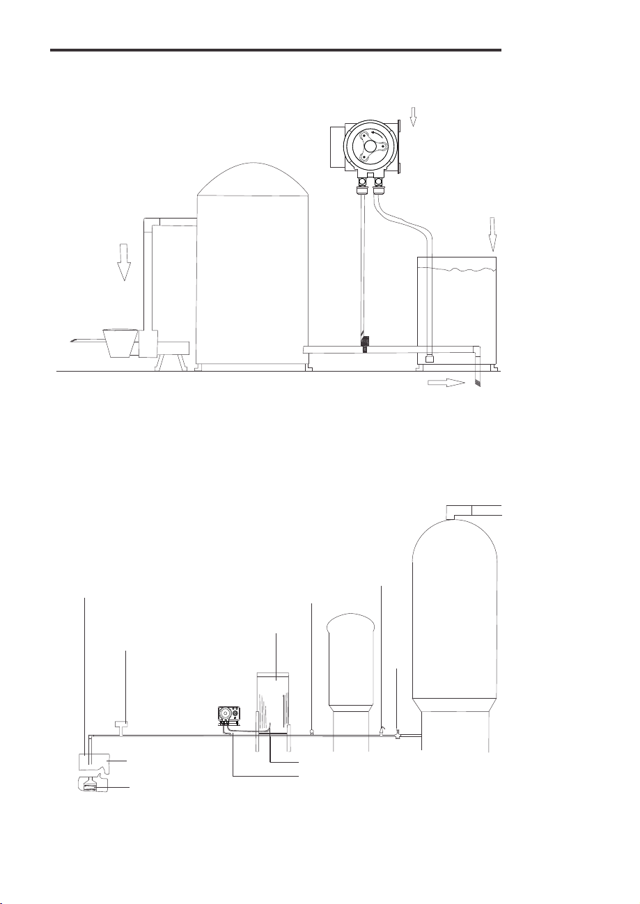
SWIMMING POOLS
Figure 1
CIRCULATION
PUMP
FILTER
INJECTOR
RETURN
LINE
SOLUTION
TANK
WATER WELLS
Figure 2
Well cover
Pressure
switch
WELL
Submersible well pump
Solution
tank
L
Pressure
guage
Suction Tube
Injector Point
Pressure
relief
valve
Drain
To system
Contact
tank
Page 5
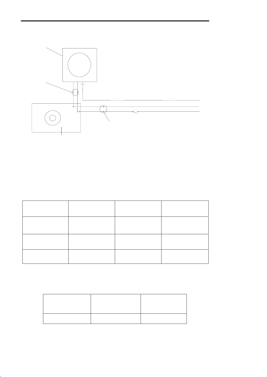
Motor
Injecting
Indicator
Light
Cycle Timer
WIRING DIAGRAM
Figure 3
WIRING DIAGRAM
A-1600T SERIES
(Timer Models Only)
Black
Red
White
Power
Indicator
Light
Power
Switch
A- 1600 SERIES
WIRING COLOR CODES
Figure 4
Page 5
Ground
Hot
Common
**************MOTOR************
VOLTAGE HOT COMMON GROUND
115v Black or Yellow Blue Green
230v Black or Yellow Red Green
24v Blue White Green
******** CIRCUIT BOARD*******
(TIMER MODELS ONLY)
HOT
(Load and Input)
Black White Red
COMMON
(Input)
LOAD
(Load)
Page 6

Page 6
OPERATING INSTRUCTIONS
SUPPLY TANK FOR CHEMICALS
Plastic containers must be designed and manufactured for this purpose. Your
container must be designed for whatever chemical you are using. Do not
place the container in direct sunlight. Ultraviolet (UV) rays attack many
materials which can cause them to become brittle.
OPERATION - MAINTENANCE
Once every week inspect tubing, and accessory valves and fittings. Inspect
all parts for signs of leaks, swelling, cracking, corrosion or discoloration. Also,
inspect the tubing for elasticity.
Cracking, crazing, discoloration, etc., during the first week of operation are
signs of severe chemical attack. If this occurs, immediately remove the fluid
from the injector. Determine which parts are being attacked and replace with
parts that have been manufactured using more suitable material.
The pump is designed to perform in a wide variety of installations. However,
the service life of the pump will vary, depending on many factors such as;
fluid , temperature, pressure, etc. Because of the wide variety of installations,
the pump has been factory tested for pressure and performance using water
only. Do not use chemicals if you are not satisfied they are compatible with
the pumps construction.
The pump tube assemblies are designed for maximum service life. However,
the service life can be adversely affected by the chemicals used, the amount
of back pressure, the motor RPM, and temperature.
The pump tube assemble should be inspected frequently. Replace the tube if
any cracking, leaking or loss of feed rate occurs.
THREADLESS AND THREADED INJECTORS
The most common problem is calcium and/or lime build up inside the injector,
foot valve and tubing. This is basic material and can easily be removed by
running a weak solution of muriatic acid through it. After flushing the pump
with clear water, place the injection fitting and foot valve with the tubing
attached in a container of weak (1-5) solution of commercial grade muriatic,
then run the pump for a few minutes. After flushing out the wetted parts with
clear water again, return pump to service. CAUTION do not allow acid and
chlorine products to come together. This is VERY DANGEROUS to your
health!
Page 7

L
R
OPERATING INSTRUCTIONS
MEASURING THE OUTPUT
Page 7
FIGURE 5
This volumetric test will take into
account installation factors such as
line pressure, fluid viscocity, specific
gravity, etc. This test is the most
accurate for measuring the injector’s
output in an individual installation.
1. With the injector installed under
normal operating conditions, place
the foot valve/strainer in a large
graduated container.
2. Fill the container with the
chemical to be injected and run the
unit until all air is removed from the
suction line.
3. Refill the container, if necessary,
and with the foot valve in the
solution, note the amount of
chemical in the container.
4. Run the injector for a measured
amount of time and note the amount
of chemical injected.
Blue-White
Injection Fitting
Discharge
Tubing
Blue-White
Suction
Tubing
Graduated
Container
(not provided)
Pump
R
ADJUSTING THE OUTPUT
A. The pause control knob adjusts the cycle timer’s time on. The model A-1600T
standard cycle timer set at one minute. (+-10%) Other cycle lengths are available.
B. To adjust the amount of time on, turn the pause control knob to the correct
setting. ½ equals approximately 30 seconds on. 3/4 equals approximately 45
seconds on, etc.
Page 8

Page 8
OPERATING INSTRUCTIONS (Con’t)
FIGURE 6
1. 2.
L
R
Hold the tube in your right hand with
“R” facing you. Note that the fitting marked “L” is
facing downward and away from you to the left. The
tube is purposely twisted to allow for the difference
between the inside length and the outside length of
the tube when installed in the pump head. Hold the
tube with your thumbs over the “R” and the “L.”
R
the fitting marked
RL
The tube will naturally curve toward the rear of the
pump head. The curve in the tubing is a patented
feature which prevents the pump tube from running
outward and against the cover.
3. 4.
L
R
Attach the plastic tube fitting (marked “R”) into the right
side of the pump head.. Push the groove of the fitting
straight into the slot. With the pump running, hold the
fitting marked “L’ with your left hand (your thumb should
be covering the “L”). At the same time, use your right
thumb to guide the tube into the pump head.
With the tubing riding well between the rollers, push the
fitting marked “L” into the chamber lock. Be sure both
fittings are pushed all the way in place.
TUBE CONNECTIONS INSTRUCTIONS
1. Connect the flow indicator end of the suction tube to pump fitting marked
“R.” Indicator to be vertical.
2. Trim the other end so strainer assembly will hang about one or two inches
above bottom of solution tank (sediment space).
3. Slide the ceramic weight over the end and attach the foot strainer
assembly.
4. Connect the discharge tube to the “L” fitting then to the injector fitting.
NOTE: A threaded injection fitting is available. Fitting is equipped with 1/4”
and 1/2” NPT threads.
RL
Pump Tube Lubricant: Place 1 or 2 drops of silicone oil on each roller to
lubricate new pump tubes or when required.
Page 9

Page 9
OPERATING INSTRUCTIONS (Con’t)
THE PUMP TUBE ASSEMBLY
A. The A-1600 Pump Tube Assemblies are designed for a service life of at least
800 hours. However, the service life can be adversely affected by the chemicals
used, the amount of back pressure, the motor RPM, and temperature. The
service life of 800 hours is based on the A-002-6 tube tested with water at 70F.
(21C), 0PSI, 45 RPM gearbox.
B. The pump tube assembly should be inspected frequently. Replace the tube if
any cracking, leaking or loss of feed rate occurs.
NOTE: Place 1 or 2 drops of silicone oil on each roller to lubricate new pump
tubes or when required.
CLEANING
A. The most common problems occur from deposits that can build up in the foot
valve, injection fitting and pump tube assembly, (wetted parts. Keeping these
parts clean will dramatically increase the life of the injector.
B. For simple maintenance cleaning, remove the injection fitting and footvalve /
strainer. Disassemble and clean the individual parts with clean water.
With these fittings removed, set the pause control to ON and run the injector
using clean water.
C. For removing harsh deposits that can build up in the wetted parts.....
1. Flush the system by pumping clean water to remove any chemicals that may
be present.
2. Run a weak solutions of muriatic acid (5%) through the wetted parts.
3. Again flush the system with clean water.
CAUTION
MURIATIC ACID WHEN MIXED WITH OTHER CHEMICALS CAN BE
EXTREMELY DANGEROUS. ALWAYS FLUSH THE SYSTEM WITH CLEAN
WATER BEFORE AND AFTER YOU ACID WASH.
D. When changing the pump tube assemble, always wipe the pumphead to
remove any debris. Clean with soap and water if necessary.
Page 10

Page 10
EXPLODED VIEW
19
17
15
Front View
12
8
4
2
1
Page 11

alve Weight
Assy. 1 Min. 115v
Page 11
CONTACT LOCAL AUTHORIZED REPAIR CENTER
FOR PARTS AND SERVICE
A- 1600 PARTS LIST
A-008-2 Gear Box Assembly 30 RPM
A-008-3 Gear Box Assembly 45 RPM
A-309-1 Motor Assy. 24v/60HZ For 30 & 45 RPM
A-149-2 Motor Assy. 115v/60HZ for 14 RPM
A-309-2 Motor Assy. 115v/60HZ for 30 & 45 RPM
A-149-4 Motor Assy. 220v/50HZ for 14 RPM
A-309-4 Motor Assy. 220v/50HZ for 30 & 45 RPM
A-149-3 Motor Assy. 230v/60HZ for 14 RPM
A-002-4 Pump Tube Assy. 1/4” OD Tygon 25.C-330-4 Tube Nut1/4 OD Tubing
A-002-4n Pump Tube Assy. 1/4”OD Norprene C-330-6 Tube Nut 3/8” OD Tubing
A-002-6 Pump Tube Assy. 3/8” OD Tygon 26.C-334-4-10 Tubing 1/4” OD x 10’
A-002-6n Pump Tube Assy. 3/8” OD Norprene C-334-6-10 Tubing 3/8” OD x10’
A-002-7 Pump Tube Assy. 7/16” OD Tygon 27.T140-4V T.I. Fitting 1/4” OD Tube Viton W/ Clamp
A-002-7N Pump Tube Assy. 7/16” OD Norprene T140-6V T.I. Fitting 3/8” OD Tube Viton W/ Clamp
1. A-011 Pumphead Cover Retaining Knob 19.C-608P Motor Housing
2. A-001 Pumphead Cover 20.C-628 Screw 6-32x2-3/4 Phil RD
3. A-002-3N Pump Tube Assy. 3/16” OD Norprene 24.C-308J Junction box assembly
A-003-1 Roller Assy. 2 Lube 29.C-346 Ceramic Foot V
4. A-003 Roller Assy. 3 Lobe 28.CF-3040 Clamp Fits 1” Thru 2-1/2”Pipe
5. A-004 Pumphead Mounting screw 10-32 x 3/4” 30.C-340-4V Foot Valve/Strainer 1/4”OD Viton
6. A-031 Pumphead Spacer C-340-6V Foot valve/Strainer 3/8” OD Viton
7. 2-010E Motor Shaft Seal 31.A-023-B Electronic Timer
8. A-005 Pumphead A-023-C Electronic Timer Assy. 1 Min. 230v
9. A-006 Motor Mount Screw 10-32 x ½ A-023-D Electronic Timer Assy. 1 Min. 24v
12. C-302 Motor Mount A-023-E Electronic Timer Assy. 2 Min. 220v
14. C-649 Bushing .50-20x.31Alum. Hex A-023F Electronic Timer Assy. 6 Sec. 115v
15. A-008-1 Gear Box Assembly 14 RPM A-023-G Electronic Timer Assy. 6 Sec. 230v
17. A-149-1 Motor Assy. 24v/60HZ For 14 RPM
A-309-3 Motor Assy. 230v/60HZ for 30 & 45 RPM
Page 12

TROUBLE SHOOTING GUIDE
SYMPTOM
POSSIBLE CORRECTIVE
Tube wears out to fast 1. High back pressure
2. Temp. above 105° F
3. Clogged injection
fitting
Injector runs noisy
1. Normal with 14 RPM
2. Worn motor bearing
Injector runs hot
1. Normal heat rise is
approx. 70° F
Solution tank is filling
instead of emptying
1. Suction & Discharge
tubing is reversed
2. Rollers worn far
beyond standard
tolerance
Swollen O-Rings 1. O-Ring material is
not compatible with
chemical being used.
1. MAX PSI = 25
2. Do not install near
a heat source
3. Clean fittings
1. None
2. Replace bearing
1. Do not install bear
a heat source
1. Connect suction
tube to fitting marked
“R” and Discharge to
“L”
2. Replace Roller
Assembly
1. Replace with
compatible O-Rings.
Cycle Timer is erratic or
run constantly
Pressure is below 25
PSI but chemical is not
injecting
2. System was not
flushed
1. Spikes or surges in
electricity caused by
“ORP” or “PH”
controllers
2. Surge protector has
been overlooked
1. Tube assembly is worn
2. Roller Assembly is worn
3. Injection fitting or foot /
valve assembly is clogged
4. Discharge tubing is to
long creating added back
pressure (especially with
high viscosity chemicals)
1. Consult controller
manufacturer
2. Replace timer
board
1. Replace tube assy
2. Replace roller
3. Clean fittings
4. Install injector as
close to injection
point as possible Trim
Discharge tubing
Page 13

REPAIR CENTERS
ARKANSAS American Pump TENNESSEE
BT Environmental, Inc 7580-A W. Tennessee St. Rock City Machine
Bill Thomason Tallahassee, FL 32304 307 3rd Avenue South
225 Castleberry Street 850-575-9618 Nashville, TN 37201
Hot Springs, AR 71901 615-244-1371
501-624-3837
CALIFORNIA (NORTHERN) Pensacola, FL 32505
Howard E. Hutching 904-432-9929
company
(Repair Center) Picard Chemical
7190 Penryn Plaza 1670 S. Congress Avenue
Penryn, CA 95663 W. Palm Beach, FL 33406
800-568-3958 561-965-3434
Swimco Electric Co. 2708 E. Randol Mill Rd.
753 Camden Avenue Arlington, TX 76011
Campbell, CA 95008 817-640-6188
408-378-2607
CALIFORNIA (SOUTHERN) Alsip, IL 60658
Blue-White Industries 708-597-5558
(Repair Center)
5300 Business Drive MARYLAND
Huntington Bch. CA 92649 Century Pool Service, Inc
714-893-8529 5020 Nicholson Court, #201
COLORADO
Denver Winpump
5754 Lamer ave
.Arvada, CO 80002
303-424-3551
CONNECTICUT Wilson, NC 27893
Cronin-Cook & Associates 800-872-7665
24 West Road
Vernon, CT 06029
860-875-0544
FLORIDA
Rice Pump & Motor Repair
5740 Powerline Road
Ft. Lauderdale FL 33309
954-776-6049
Jerry Lee Chemical Co.
3407 W. Old Fairfield Drive
ILLINOIS
Mullarkey Associates
(Repair Center)
12346 S. Keeler Ave.
Kensington, MD 20895
301-231-8999
NORTH CAROLINA
Southern Industrial Sales
1903 Herring Avenue
SOUTH DAKOTA
Son-Aqua Distributing
Jim Robinson
2447 W. Main Street
Rapid City, SD 57702
605-343-7716
TEXAS
Alamo Water Refiners
13700 Hwy. 90 West
San Antonio, TX 78245
210-677-8400
Shelter’s Water Refining
Robert Shelton
Page 14

LIMITED WARRANTY
Your new pump is a quality product and is warranted to be free of
defects as set down it this policy. All parts, including rubberized goods
and labor are covered under warranty for 90 days from date of purchase. Used peristaltic tubes are not warranted. Parts (excluding
rubberized goods and labor) are covered for a period of 12 months
from date of purchase. Warranty coverage does not include damage to
the pump that results from misuse, carelessness, abuse, or alteration.
Only the repair or replacement of the pump is covered. The manufacturer does not assume responsibility for any other loss of damage.
Warranty status is determined by the pumps serial number. The serial
number label must be on the pump to obtain warranty coverage.
Enclose your invoice or sales receipt, with date of purchase, when you
return the pump for warranty repair. Warranty status will be verified by
the factory or authorized service center.
Also: Please be advised, injections and metering devices are not
intended as a means of treating water to render it suitable for human
consumption. When used as hypochlorinators, they are meant to
destroy bacteria and algae contamination, before it’s removal by
filtration. Acid and soda injectors are used for pH control (balance).
The injectors are factory tested with water only for pressure and
performance. Installers and operators of these devises must be well
informed and aware of the precautions to be taken when injecting
various chemicals, especially those considered hazardous or dangerous. Should it be necessary to return an injector for repair or service,
you must attach information regarding the chemical used as some
residue may be present within the unit and could be hazard to service
personnel.
The manufacturer will not be liable for any damage that may result by
the use of chemicals and injectors and its components. Thank you.
PROCEDURE FOR IN-WARRANTY REPAIR
Carefully, pack the pump to be repaired, included the foot valve and
injection fitting. Enclose a brief description or the problem, as well as
original invoice or sales receipt showing date fo purchase. The receipt
will be returned with the unit. Prepay all shipping costs. COD shipments will not be accepted. Warranty repair service must be preformed
by the factory, or an authorized service center. Damage caused by
improper packaging is the responsibility of the sender.
80000-038 09-03-2010
 Loading...