

Page 1
DC INVERTER HEAT PUMP
(Split Type)
- User Manual -
Please read this manual carefully before installing this unit and keep it for future reference.
Page 2

DC Inverter Heat Pump - Split Type
Table of Contents
IMPORTANT SAFETY PRECAUTIONS....................................................................................... 1
Section 1: Introduction.................................................................................................................. 2
Product Overview........................................................................................................................ 2
Overview of The Unit...................................................................................................................2
Section 2: Installation.....................................................................................................................3
Installation Location....................................................................................................................3
Unit Installation Requirements.................................................................................................4
Section 3: Operating Heat Pump................................................................................................. 6
General Instruction......................................................................................................................6
Control Panel
Controller Operations................................................................................................................. 7
Section 4: Error Code
Section 5: Electrical Wiring Diagram....................................................................................... 15
................................................................................................................................
...................................................................................................................
14
6
Page 3
DC Inverter Heat Pump - Split Type
1
Important Notice for Antifreeze to Avoid heat pump broken
1.
Water
flow switch MUST be installed during installation for heat pump air conditioning side to
ensure proper wa
ter flow.
2.
Must
use enough brine (glycol) in the wa
ter system
in cold area. If the air temp is lower than -0°C
,
for the safety,you mustuse brine (glycol) as the fluid in the heatpump water system instead of
pure wa
ter.
3.
Must keep the electricity power supply always connected even when you don'tuse the heat
pumps.
Our
heat pump has anti-freeze function if with electricity connected. SoIfwithoutenough
glycol (antifreeze liquid) and if the electricity is cutoffby accide
nt for
more than 30 minu
tes
in
winter,you need to drain out all the inside wa
ter to protect
the heatpump from being frozen.
IMPORTANT SAFETY PRECAUTIONS
Important Notice To User:
1.Before installing and using this product, please read this instruction in detail, otherwise it may
cause damage to the equipment or operator injury and property loss.
2.With the continuous progress of science and technology, product series and specifications will be
adjusted accordingly, so stay tuned for the latest product information.
3.If you need any technical advice while reading this manual, please contact the company or local
agent.
4.Notices section
4.1 When installing heat pump units, please check whether the corresponding power supply
capacity meets the requirements of heat pump units. See the nameplate on the unit for
details.
4.2 Be sure to install electric leakage protection device.
4.3 Heat pump unit must be reliably grounded. It is strictly forbidden to use the unit without
reliable grounding.
4.4 Electrician wiring must refer to wiring diagram.
4.5 In order to use safely, do not alter or repair heat pump units without permission.
4.6 It is strictly forbidden to insert any tool into the heat pump unit, so as to avoid damage to the
unit or accidents caused by the fan (children must not).
4.7 Do not use the unit in the condition of removing grids or sheet metal, in order to avoid
accidents or abnormal operation of units.
4.8 When the unit is immersed in water, please contact the factory or its maintenance department
immediately. The unit must be re-used after being inspected by the technician.
4.9 Non-qualified technicians shall not adjust the set parameters of the unit, controller dialing,
valves and other components within the unit.
4.10 When maintaining and repairing, please cut off the power supply of the unit to avoid electric
shock and accident.
This document is subject to change without prior notice.
Page 4
DC Inverter Heat Pump - Split Type
2
Section 1: Introduction
Product Overview
DC Inverter Heat Pump is suitable for users who need separate AC cooling, separate AC heating,
two in one, three in one, etc. It can provide air conditioning, heating and hot water for families,
apartments, small industrial sites, etc.
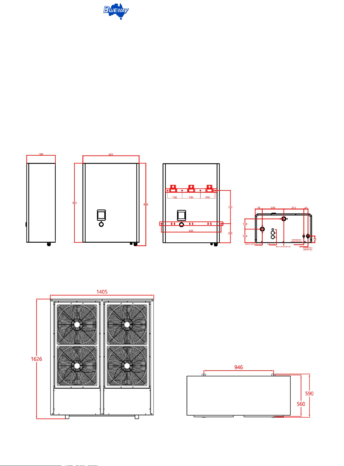
Overview of The Unit
(Indoor unit of EDHP-30S, dimensions: mm)
(Outdoor unit of EDHP-30S, dimensions: mm)
This document is subject to change without prior notice.
Page 5
DC Inverter Heat Pump - Split Type
3
Section 2: Installation
The following general information describes how to install the heat pump.
Note: Before installing this product, read and follow all warning notices and instructions.
Only a qualified service person should install the heat pump.
Installation Location
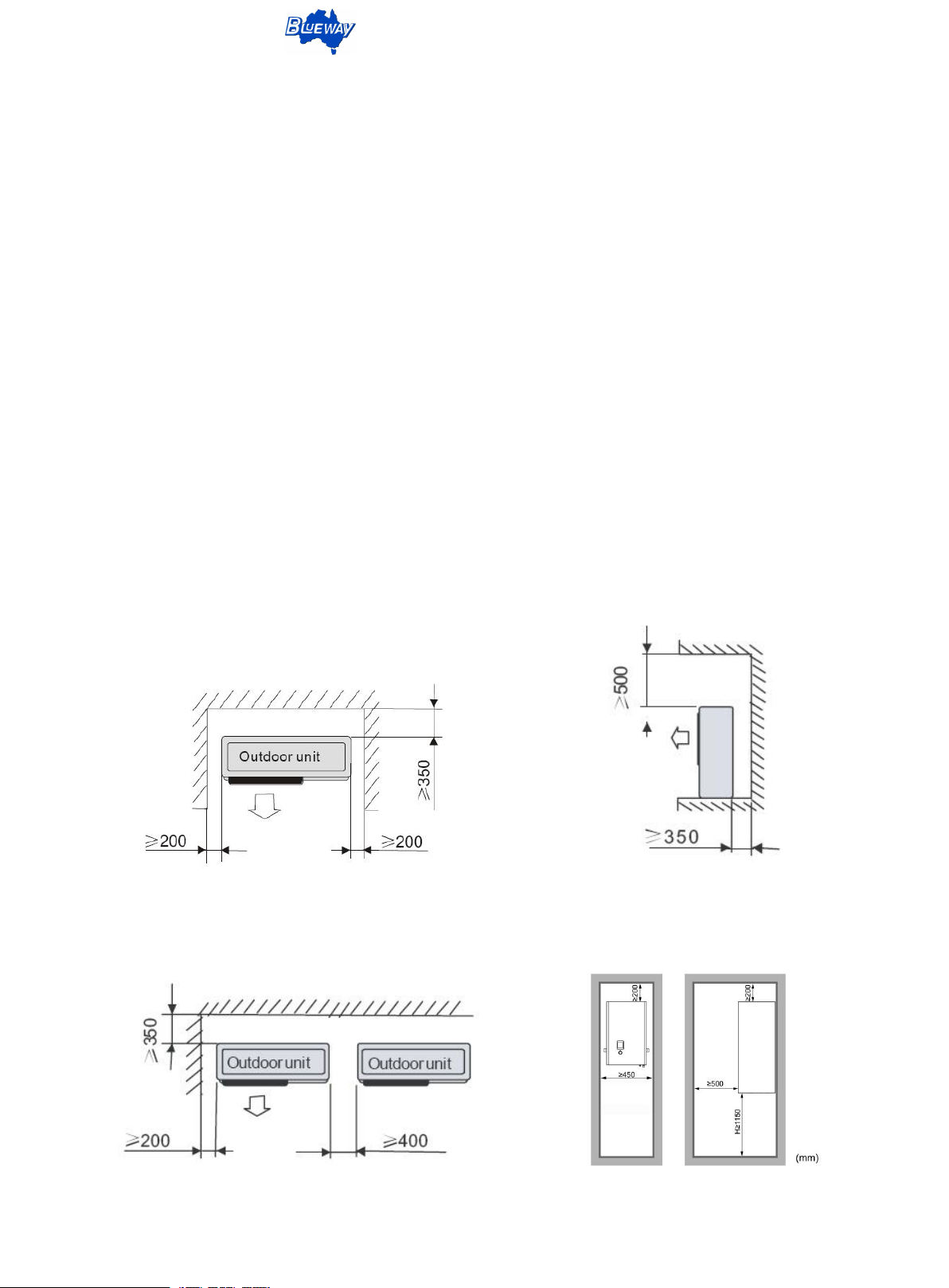
It should be installed in a well-ventilated place with a large space.
·
·Installation position should ensure that the air inlet and outlet are unimpeded, the air outlet is not
less than 3 m and the air inlet is not less than 0.35 m. The distance between two adjacent units is
not less than 0.4 m.
·Drainage ditches or drains are provided near the installation location for easy drainage.
Do not install the main unit in a place where there is pollution, corrosive gas, sand, leaves, etc.
·
The installation location shall not be close to places where it is easy to explode and open fire.
·
·Choose a reasonable installation direction according to the local wind direction to avoid the
opposite direction of outlet wind and inlet wind.
No obstacle in front of the unit Obstacle above the unit
Several units in a row
This document is subject to change without prior notice.
Page 6

DC Inverter Heat Pump - Split Type
4
Unit Installation Requirements
·The unit installation foundation can be concrete structure, steel bracket, anti-vibration rubber pad,
and the foundation surface should be flat to ensure stable running of the unit.
·The basic design can be designed according to the operation quality of the unit. (see technical
parameter sheet or nameplate)
Bolts are used to fix the bottom of the unit, and there shall be drainage ditch or outlet on the
·
ground.
·Ensure that the unit is upright and not tilted after installation.
1.Pipe connection
·Pipe installation starts with the heat pump main unit and ends with buffer tank. The distance
between heat pump unit and buffer tank should not exceed 4m, Water pipe connection should be
horizontal and vertical, as far as possible to reduce the bending, as far as possible to reduce the
use of 90-degree elbow, reduce the resistance loss of the water system.
When planning the equipment layout according to the user's site, the shortest andstraightest
·
waterway should be sought, and reserve a reasonable operating space between the equipment.
·Filters should be installed in the return pipe of the unit. Ball valves should be installed at both ends
of filter to facilitate the cleaning of filter. The filter should be cleaned once every six months.
·Install the hot water tank unit, please confirm that the hot water tank is equipped with a safety
valve.
For units installing AC water tanks, please install expansion water tanks in pipes to avoid the
·
expansion of pipes during heating running.
·Please connect the inlet and outlet pipes of the heat pump according to the label on the unit, the
inlet pipe of the heat pump is connected to the lower water inlet of the buffer water tank, and the
outlet pipe is connected to the upper water inlet of the water tank.
·Pipes connection must be preceded by the insulating sleeve. The thickness of one side of
protective sleeve should not be less than 10 mm.
·The pipes installation should be fixed with pipe clamp at the predetermined installation position
to prevent pipe deformation and bending.
Where the ball valve is installed, a fixed pipe clamp should be installed near the valve to avoid the
·
torque of the switch valve being transmitted to the pipe.
·After the pipeline connection is completed, the whole pressure test must be carried out to confirm
that the seal can pass through the water.
·After all the pipelines are installed and sealed, the water is supplied to the heat pump and water
tank through the tap water. When the water is replenished, it must be confirmed that the air in the
pipeline and the water tank has been discharged cleanly. There is air in the system, which may
cause water flow error or insufficient heat pump capacity, and the COP decreases.
2.Electrical Connection
The power installation personnel must have an electrician certificate approved by the legal
organization, the power installation and connection, please follow the relevant regulations.
This document is subject to change without prior notice.
Page 7
DC Inverter Heat Pump - Split Type
5
2.1 Power connection
Heat pump must use circuit breaker.
·
The power supply must be consistent with the power requirements on the unit nameplate.
·
·The core diameter of the power supply wire must meet the actual needs of the unit.
The power supply must be reliably grounded.
·
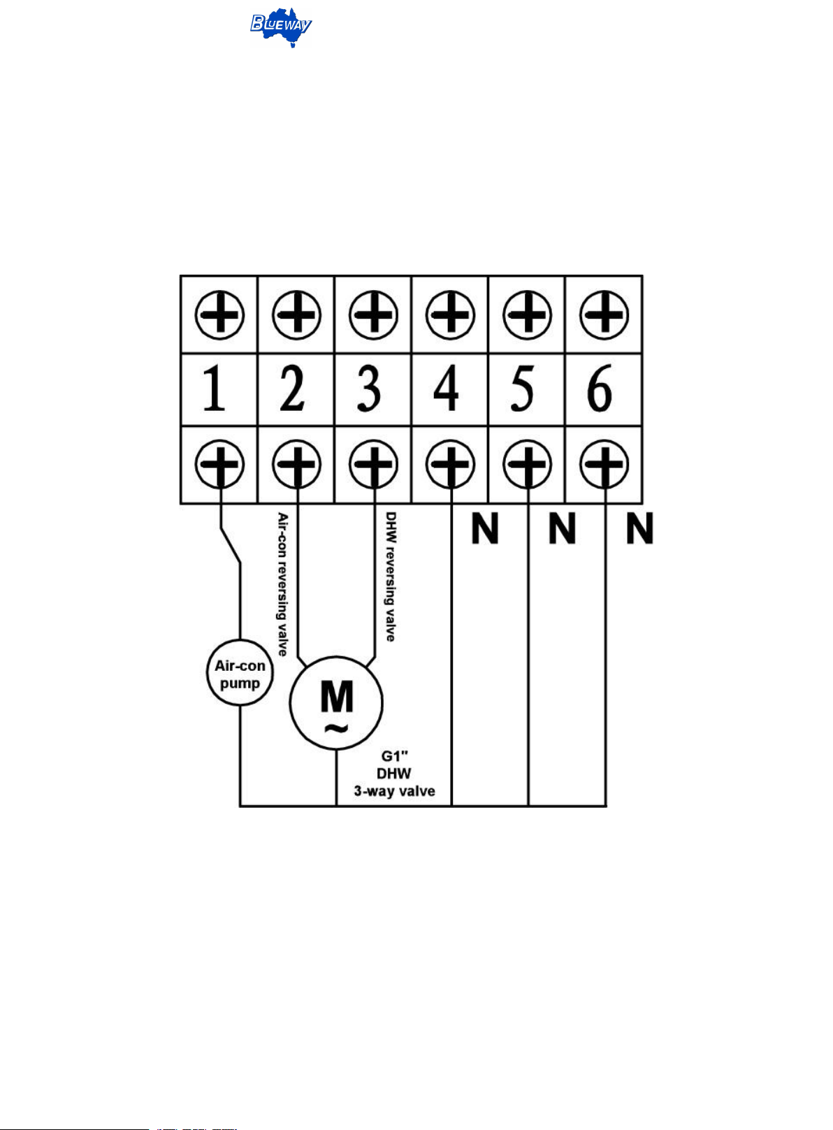
2.2 Connection of external electrical appliances
(Split type, hot water three-way valve wire connection)
This document is subject to change without prior notice.
Page 8
DC Inverter Heat Pump - Split Type
6
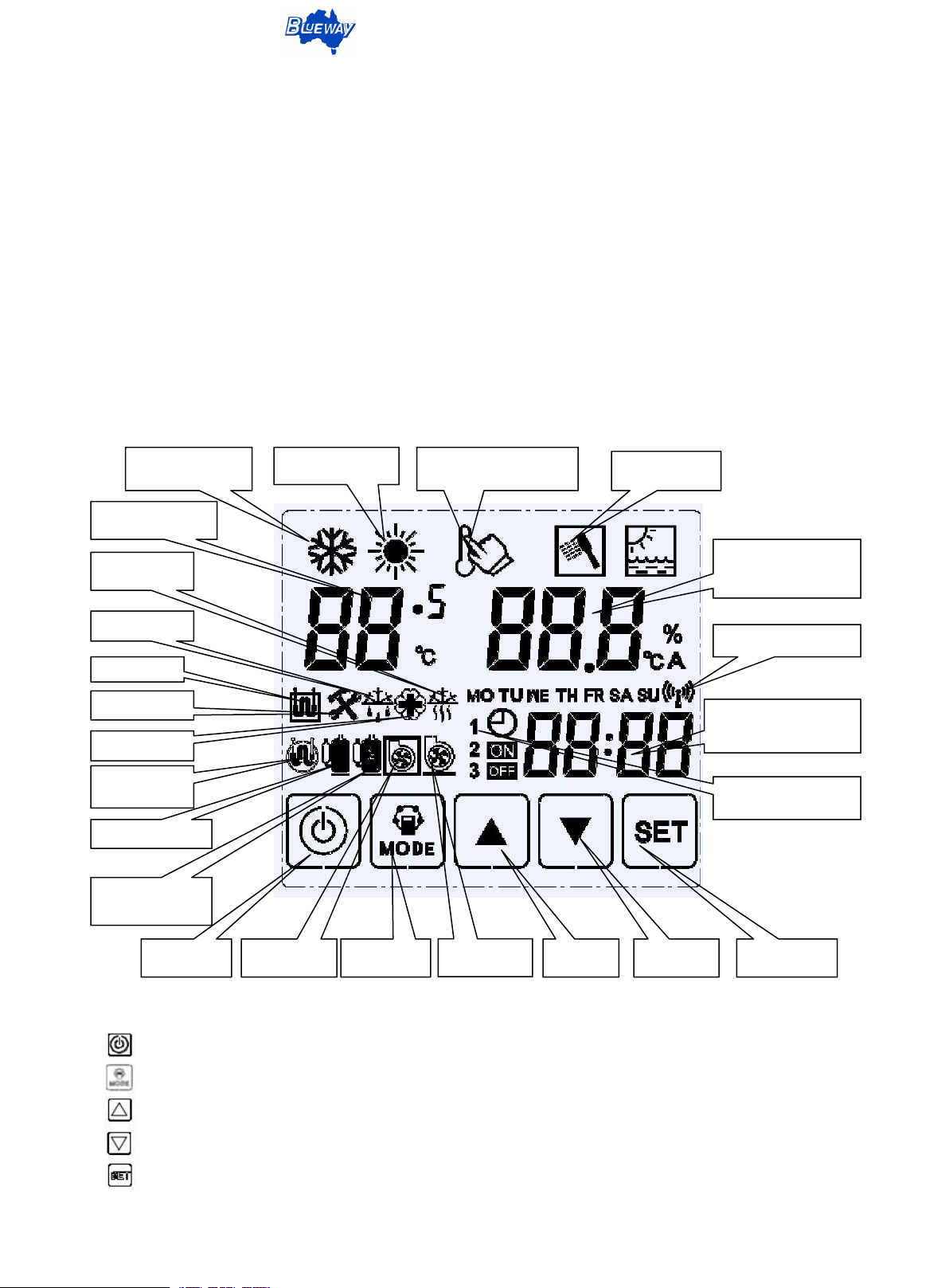
Cooling mode
Heating mode
Target temp. setting
DHW mode
AC inlet temp.
Anti freeze
Temp and Error,
parameter value
display area
Defrost icon
WIFI control signal
Timer period/Para No.
Timing icon
AC compressor
Hot water
compressor
AC Pump
Mode key
DHW Pump
Plus key
Minus key
Confirm key
AC heater
Error icon
Sterilization
Hot water
Power key
Section 3: Operating Heat Pump
General Instruction
The operation panel features:
1. Touch screen for higher operating sensitivity and unlimited key operations.
2. Minimal electromagnetic susceptibility and interference.
3. Stylish appearance for easy viewing purposes.
4. Dust and water Proof.
5. Installed on wall indoor for convenient operation.
6. Automatic Key Lock function.
Control Panel
Buttons definition
“ ” On/Off key: Turn on, turn off, exit the operation interface and return to the main interface.
“ ” Mode key: Mode Conversion, Clock, Timing Operations.
“ ” Plus key: Set temp, hour, minute, parameter increase.
“ ” Minus key: Set temp, hour, minute, parameter reduction.
“ ” C-Key: Confirmation of settings, check error, check parameter, parameter setting interface.
This document is subject to change without prior notice.
Page 9
DC Inverter Heat Pump - Split Type
7
Controller Operations
After 60S without operation, the screen is locked, the background light is off, any key is pressed,
the screen is unlocked, and the background light is bright, so it can be operated.
1.On/off
In the shutdown state,press button, the unit is in the power on state, the mode display area
shows the current running mode. Press button once again, the unit is turned off, the mode display
area does not show.
2.Mode option
In the power-on state, touch key,can switch operation modes in turn,thethree in one unit can
select the following five operation modes, and the user can select the operation mode according to
actual needs.
·Select the AC Cooling only, the display area only shows the cooling icon .
·Select AC Cooling+ DHW, the display area shows the cooling icon + DHW .
·Select the AC Heating only, the display area only shows the heating icon .
·Select the AC Heating+ DHW, the display area shows the heating icon + DHW .
·Select the DHW only, the display area only shows the DHW icon .
3.Target temp. setting
Touch Key or key, setting symbol is flashing, continue to touch or key to set
the target temp. Touch key, switching mode. Set target temp. for different modes, touch
return to the main interface directly, or automatically return to the main interface after 20S is not
operated.
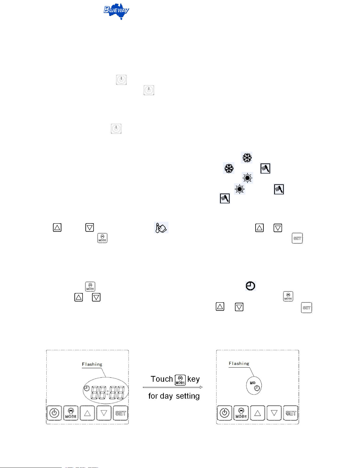
4.Clock and weekly settings
Continuous press 6S, enter the interface of clock setting, clock symbol and clock digital
flashes, press or adjust the clock in units of 1 minute, after the time is set. Press switch
to the week setting, clock symbols and week symbols flash, press or change week, press
confirm, after the clock and week settings are completed, it will automatically return to the main
interface.
Clock setting Day setting
This document is subject to change without prior notice.
Page 10
DC Inverter Heat Pump - Split Type
8
5.Timing setting
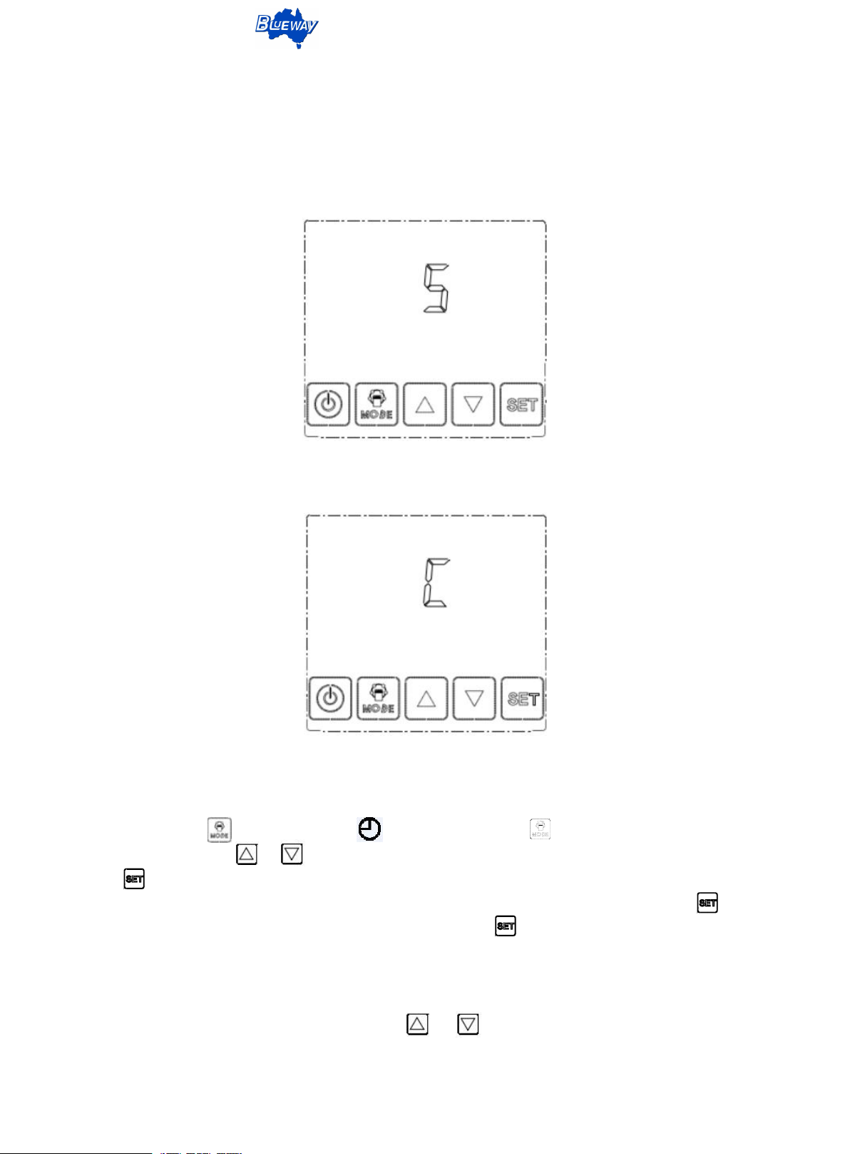
Timing settings are divided into two types: single-time validity and cyclic validity. After setting
single-time validity, the timing settings are executed only once. After the completion of the timing
action, the timing settings are automatically canceled. Once the cycle is valid, the cycle is weekly.
Single timer
Circulation timer
5.1 Single timing setting
Continuous press 6S, clock symbol flashing, then press again 6S, enter the timing
setting interface, press or , select the icon "S", indicates that the timing single-time validity,
press enter timing setting. Timing settings are set from Monday, three timing start points can be
set every day, three timed shutdown points, if a timing point does not need to be set, press skip
directly, after the timing setting of the day is completed, touch switch to Tuesday's timing setting
until Sunday.
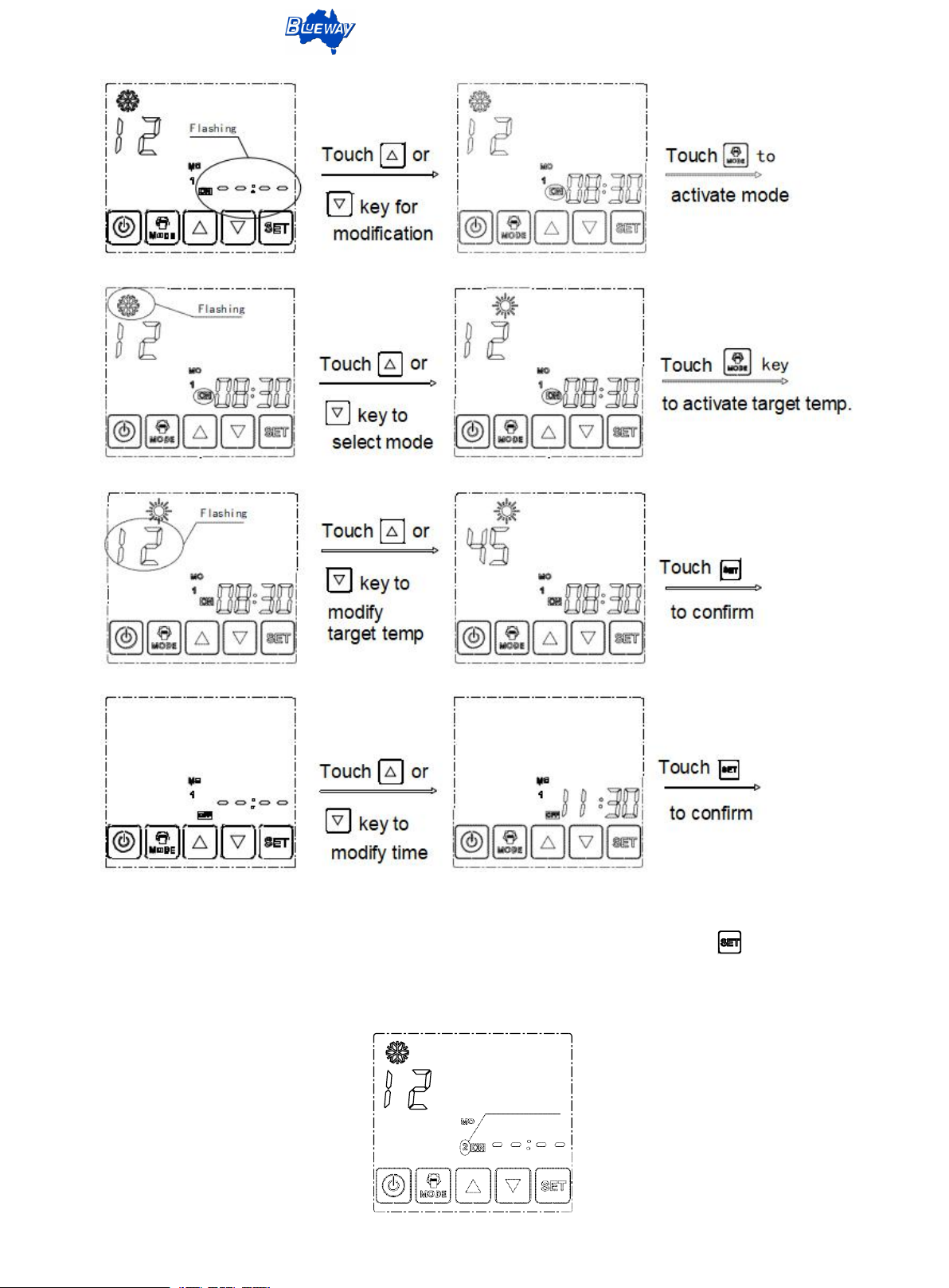
5.1.1 The first period of timer on setting: Timing on can set the start time, operation mode, target
temp. After entering the timing interface, touch or activation time value, modify the required
timing time.
This document is subject to change without prior notice.
Page 11
DC Inverter Heat Pump - Split Type
9
The second timer
5.1.2 The second period of timing setting: After the first period of timing is set, touch enter the timing
setting of the second period. The setting method of timing in the second period is the same as that in the
first period.
This document is subject to change without prior notice.
Page 12
DC Inverter Heat Pump - Split Type
10
day 2 timer
The third timer
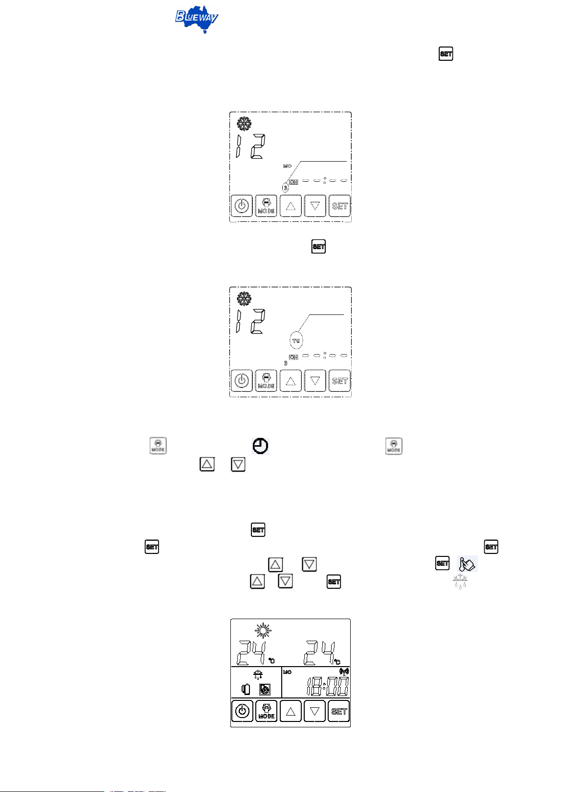
5.1.3 The third period of timing setting: After the second period of timing isset, touch enter the timing
setting of the third period. The setting method of timing in the third period is the same as that in the
second period.
5.1.4 After Monday's timing setting is completed, touch enter Tuesday's timing setting, the setting
method is the same as above.
5.2 Cycle timing setting
Continuously touch 6S, clock symbol flashing, keep touching again 6S, enter the
timing setting interface, press or select icon “C”, indicates that the timing cycle is valid, and
then the operation is the same as the single timing setting.
6.Forced defrost
In the on and off state, continuously touch 6S, enter the user parameter check interface, then
continuously touch over 6S, the password interfacewill display. Input the password 33, press
confirm. Select the parameter item by touching or , display F00, short press , flashes,
then set the parameter value 2 by touching or , press confirm, defrost symbol flashing.
Once finish defrosting, the defrost symbol will disappear.
This document is subject to change without prior notice.
Page 13
DC Inverter Heat Pump - Split Type
11
Check Para value.
Check Para
item
.
Change Para value.
Setting
Para item.
7.Parameter check & change
7.1 Parameter check
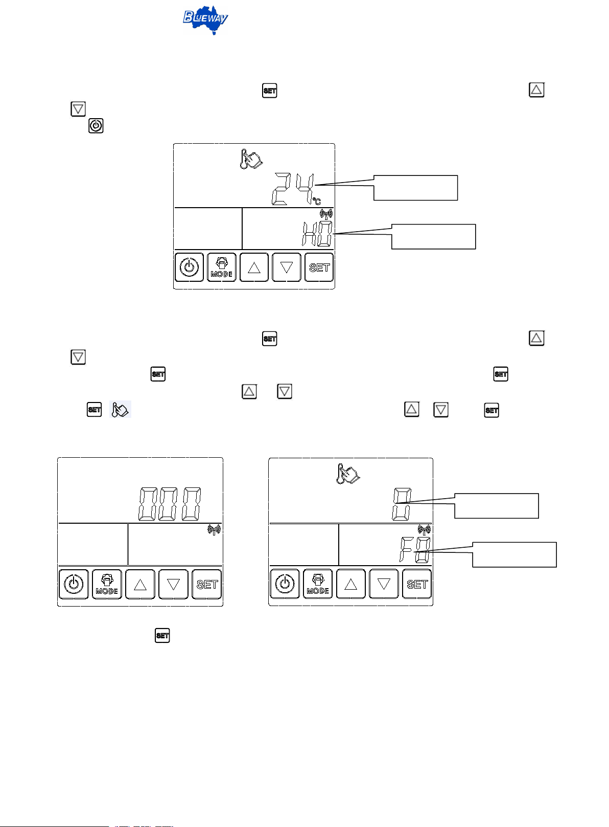
In the on and off state, continuously touch 6S, enter the user parameter check interface, touch
or each parameter value can be checked separately, then display Hxx, (such as H00, H01......),
touch or return to the main interface after 60S has no operation.
7.2 Parameter change
In the on and off state, continuously touch 6S, enter the user parameter check interface, touch
or each parameter value can be checked separately, then display Hxx, (such as H00, H01......),
continuously touch over 6S, the password interfacewill display. Input the password, press confirm.
Select the parameter item by touching or , display Fxx, (for example, F00, F01......), short
press , flashes, then set the desired parameter value by touching or , press confirm.
Password Input Parameter Setting
If it does not press confirm, the parameter settings will be invalid, and will return to the main
interface after 10S has no operation.
Once all the desired parameter values have been finished changed, wait 30S for the whole data
save. After that, cut off the power, wait for 3 minutes, then power on, the unit will run according to
the updated instructions.
Notice: Different setting parameter items corresponding to different access permissions. Do not
change the parameters without understanding its meaning to avoid unit abnormal operation.
This document is subject to change without prior notice.
Page 14
DC Inverter Heat Pump - Split Type
12
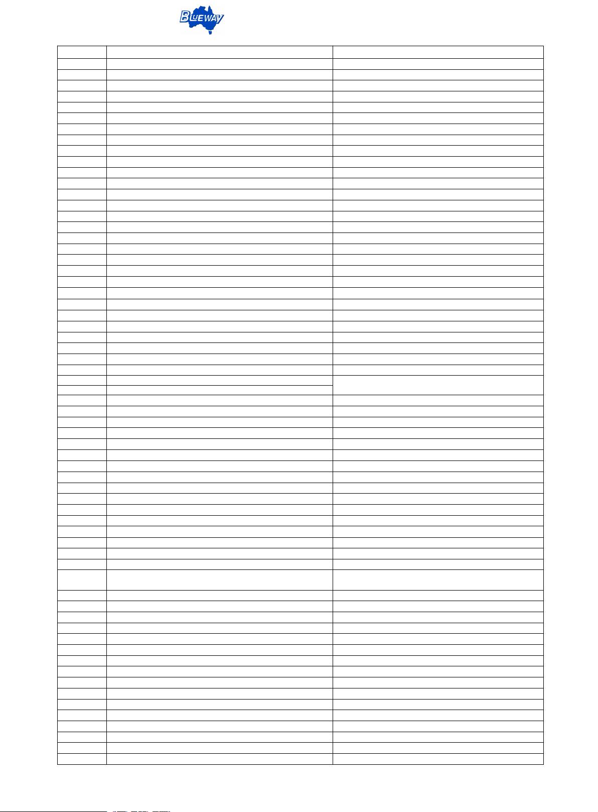
Para No.
Parameter Item
Parameter Description
H0
Inlet temp
Heat pump inlet temp
H1
Outlet temp
Heat pump outlet temp
H2
Tank temp
Hot water tank temp
H3
Outdoor ambient temp
Outdoor ambient temp
H4
Indoor ambient temp
Indoor ambient temp
H5
Compressor exhaust temp
Compressor exhaust temp
H6
Compressor suction temp
Compressor suction temp
H7
Condenser coil temp
Condenser coil temp
H8
Plate heat exchanger temp
Plate heat exchanger temp
H9
Auxiliary inlet temp
EVI series valid
H10
Auxiliary outlet temp
EVI series valid
H11
Water source side outlet temp
GEO series valid
H12
Water source side inlet temp
GEO series valid
H13
IPM Radiator temp
IPM Radiator temp
H14//
H15
Current Compressor frequency
Current compressor operating frequency
H16
Electric Current
Electric current
H17
EEV opening degree
Half of the opening of the EEV
H18
EVI opening degree
EVI Half of the opening of the EEV
H19
Water flow volume
Unit:L/min
H20
Refrigerant Low pressure
Compressor suction side pressure, Unit: 0.01Mpa
H21
Refrigerant High pressure
Compressor exhaust side pressure, Unit: 0.1Mpa
H22
EC fan1 speed
EC Fan 1 speed (Unit: rpm/min)
H23
ECfan2 speed
EC fan2 speed (Unit: rpm/min)
H24
Compressor start requirements
H25
Stop code
Compressor stop code
H26
Previous stop code2
H27
Previous stop code3
H28
Previous stop code4
H29
Compressor accumulated running, Hour * 1000
Total running hours of compressor=H29+H30.
Unit: Hours; Range:0~999999
H30
Compressor accumulated running Hour
H31
Defrost accumulated count
Total defrost times
H32
PCB Code
PCB Hardware version number
H33
PCB Software code
H34
Software version No.
H35
Wire controller software code
H36
Wire controller software version
H37
Local host address
H38
Defrost cycle
H39
Defrost maximum time
H40
Defrost enter temp
H41
Defrost exit temp
H42
Allows to start the defrost air temp
H43
Temp difference between defrosting temp below -7 °C
H44
Temp difference of defrosting at 3 °C ambient temp
H45
Temp automatic curve
H46
Temp automatic curve offset
H47
The highest value of the automatic temp curve
calculation result
H48
Model function option
H49
AC water temp setting upper limit
H50
AC water temp setting lower limit
H51
Hot water temp setting upper limit
H52
Compressor max target temp upper limit
H53
AC electric heater function option
H54
Hot water heater function option
H55
Water Pump operation mode
H56
Method 2 water Pump Start IntervalTime
H57
Power on auto-start function
H58
AC hysteresis temp
H59
Hot water hysteresis temp
H60
AC electric heater allows starting ambient temp
H61
Hot water heater allows starting ambient temp
H62
Night running mode
0-invalid; 1-valid
H63
Night running mode starting
Enter Night Mode
This document is subject to change without prior notice.
Page 15
DC Inverter Heat Pump - Split Type
13
H64
Night operation mode end
Exit night mode
H65
Night mode running ratio
Night mode compressor and DC fan output ratio
H66
Whether the Room linkage switch is enabled
0- not enabled; 1 - enabled
H67
Heating target temp
Heating mode target temp setting
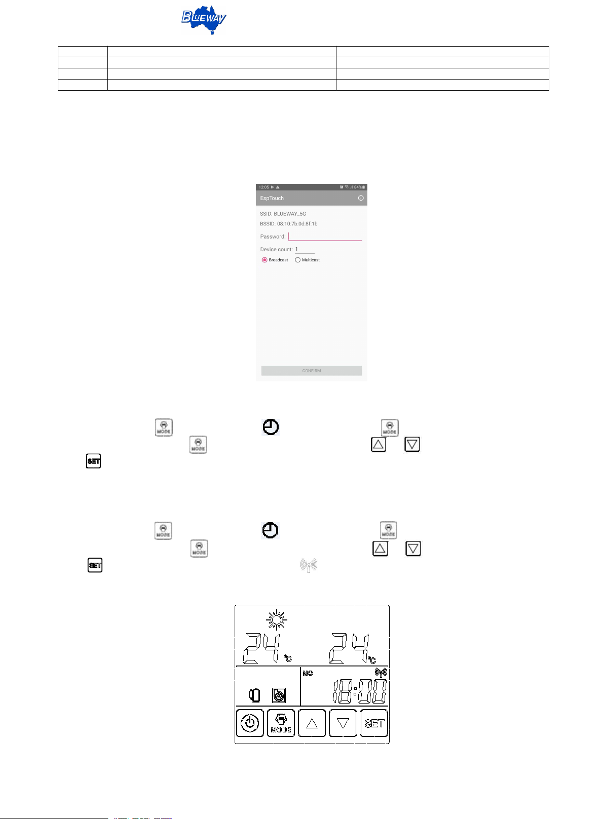
8.WIFI connection setting
8.1 Preliminary work
Install appointed software on the cellphone, cell phone needs to connect with the WIFI. Open the
app, SSIP shows the name of WIFI, enter the WIFI password, the interface as follows:
8.2 Controller connects to the WIFI setting
Continuously press 6S, clock symbol flashing, then press again 6S, enter the timing
setting interface, then press 6S, enter the password 99, press or to adjust the password,
press to confirm, shows 1 rst, then press Confirm on the cellphone within 2 seconds, then connection
starts. IP address will display when connects successfully, then can exit the app.
8.3 Remote server connection
Continuously press 6S, clock symbol flashing, then press again 6S, enter the timing
setting interface, then press 6S, enter the password:98, press or to adjust the password,
press to confirm, shows 2 rst, then WIFI symbol will be flashing, which means the unit is
connecting to the remote server, and the WIFI symbol will fixed display once finish connection.
This document is subject to change without prior notice.
Page 16
DC Inverter Heat Pump - Split Type
14
No.
Error Code
Error Item
Meaning
1
HP / E01
High pressure switch disconnects
High pressure switch disconnects
2
E02
High pressure protection
High pressure switch disconnects for 3 times
when running
3
LP / E03
Low pressure switch disconnects
Low pressure switch disconnects
4
E04
Low pressure protection
Low pressure switch disconnects for 3 times
when running
5
E06
Compressor current protection
Over current reaches 3 times when running
6
E08
Compressor discharge temp. protection
Compressor discharge temp. is too high for 3
times when running
7
E09
Compressor discharge temp. sensor error
Compressor discharge temp. sensor is loosed or
damaged
8
E10
Compressor suction temp. sensor error
Compressor suction temp. sensor is loosed or
damaged
9
E11
Condenser coil pipe temp. sensor error
Condenser coil pipe temp. sensor is loosed or
damaged
10
E12
Ambient temp. sensor error
Ambient temp. sensor is loosed or damaged
11
E14
Inlet water temp. sensor error
Inlet water temp. sensor is loosed or damaged
12
E15
DHW water tank temp. sensorerror
DHW water tank temp. sensor is loosed or
damaged
13
E16
Outlet water temp. sensor error
Outlet water temp. sensor is loosed or damaged
14
E17 / FLO
Water flow error
Insufficient flow or flow meters damage
15
E19
Ambient temp. over-lowprotection
Ambient temp exceeds allowable range
16
E20
Phase-sequence protection
17
E21
Indoor and outdoor PCB comm. error
18
E22
Password runs
19
E23
Eprom error
20
E29
1# Evaporator temp. sensor error
1# Evaporator temp. sensor is loosed or
damaged
21
E38
Inlet water temp. and outlet water temp.
difference is too large
22
E61
Plate heat exchanger temp. sensor error
1# Plate heat exchanger temp. sensor is loosed
or damaged
23
E63
Plate heat exchanger protection
1# Plate heat exchanger detect temp. is too low
for 3 times when running
24
E70
Inverter module comm. error
25
E71
High pressure sensor error
26
P74
Do not start as the monoblock or outdoor unit
is abnormal
27
P76
Low pressure sensor error
28
P77
Running frequency is abnormal
29
EN
Control panel & comm. board comm. error
Control panel & comm. board have no
communication for 30 seconds
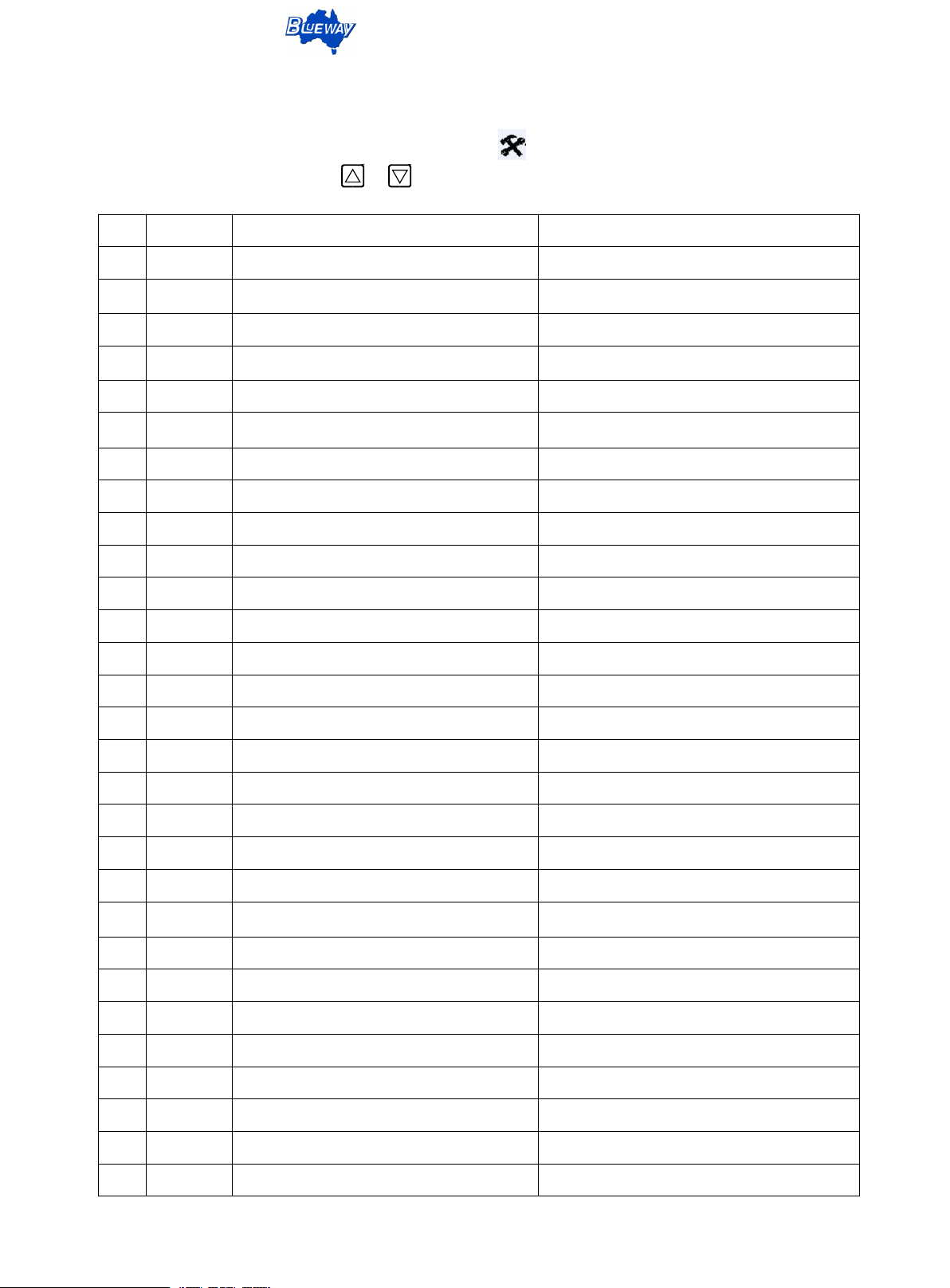
Section 4: Error Code
When the unit occur error, the error indicator symbol occur, and the error code is displayed in
the error display area. Touch the or can view other error items.
This document is subject to change without prior notice.
Page 17
DC Inverter Heat Pump - Split Type
15
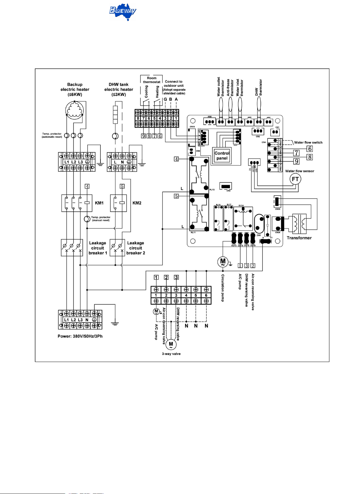
Section 5: Electrical Wiring Diagram
(Indoor Unit of EDHP-30S)
This document is subject to change without prior notice.
Page 18
DC Inverter Heat Pump - Split Type
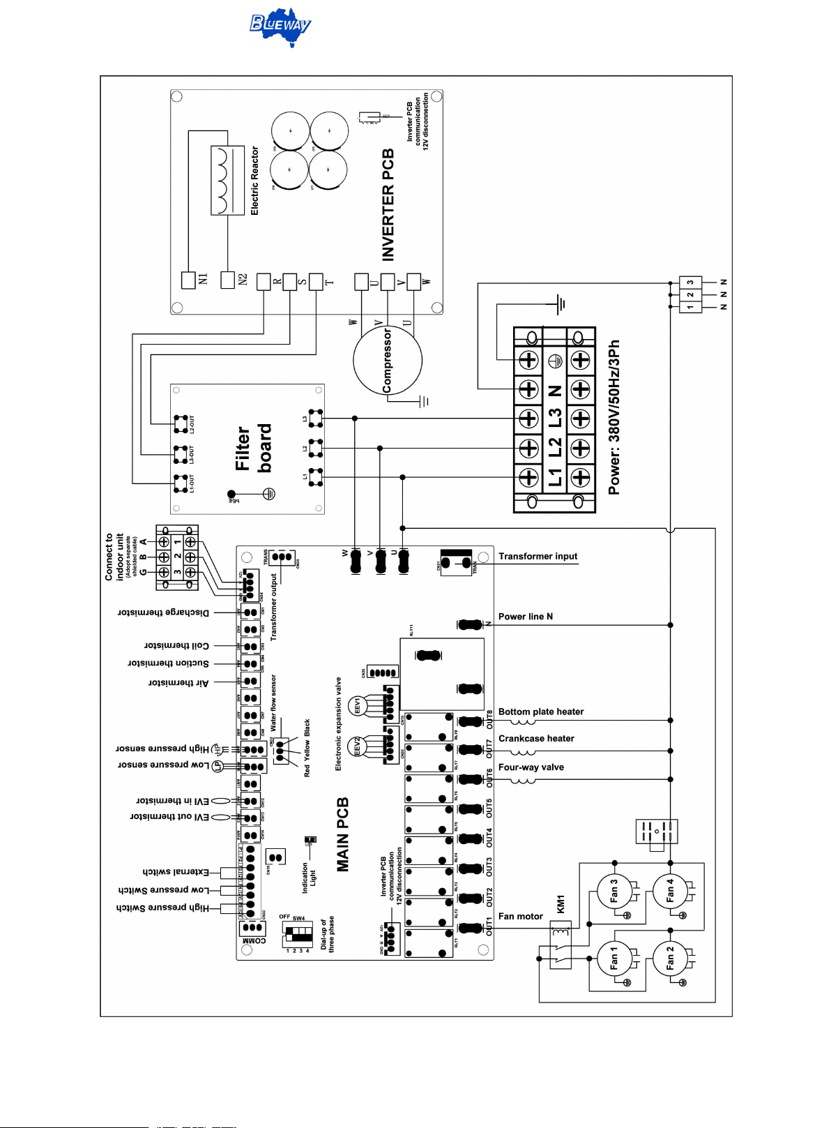
16
(Outdoor Unit of EDHP-30S)
This document is subject to change without prior notice.
 Loading...