

Page 1
AUDIO MANAGEMENT CONTROLLER (AMC) MANUAL
WINDOWS AND OS X VERSION 10.3
Page 1
Page 2

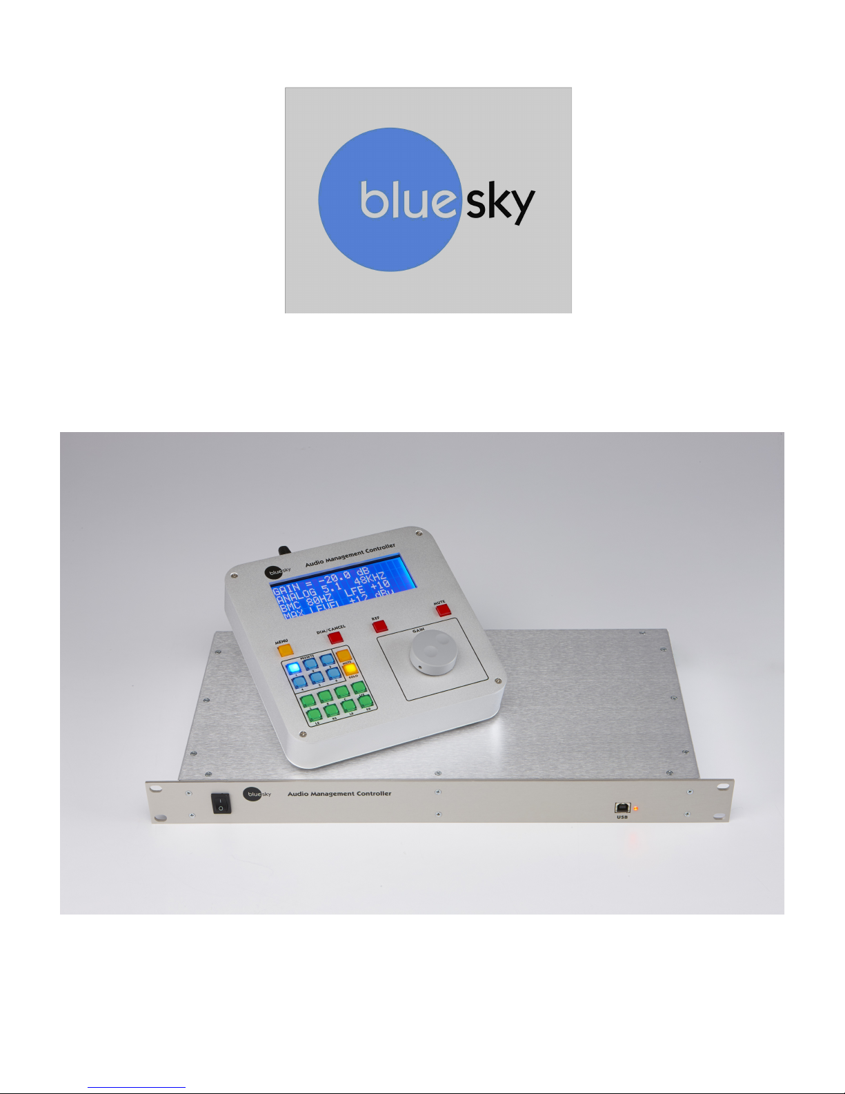
DESCRIPTION
The Blue Sky Audio Management Controller (AMC) is an 8-channel audio DSP platform with both
24-bit digital and analog I/O.
Each channel of the AMC has a sample rate converter (by stereo pair), a 31 band 1/3 octave
equalizer, eight parametric / free assignable filters, individual channel delays, and lip-sync delay.
A 16x8 cross-point mixer allows any input to be mixed to any output.
The flexible bass management system can be customized on a channel-by-channel basis, or
turned-off completely.
The AMC has 6 presets, each of which stores complete setup information, including filter setting,
I/O configuration, delays, etc.
The AMC includes control software that is a Windows and OS X application that connects through
the USB port.
The AMC includes SRO (Sound Room Optimization) software which includes an MLS based
measurement system with auto room correction or expert manual mode, correcting the in- room
speaker response to a user definable target curve.
Requires firmware and software 5.13 or above.
Page 2
Page 3

Table of Contents
DESCRIPTION...................................................................................................................................2
AMC FEATURES................................................................................................................................4
IMPORTANT SAFETY INSTRUCTIONS...........................................................................................5
AMC FRONT PANEL..........................................................................................................................7
AMC REAR PANEL............................................................................................................................7
1. POWER......................................................................................................................................7
2. CHANNEL ASSIGNMENTS.......................................................................................................7
3. ANALOG I/0...............................................................................................................................8
4. DIGITAL I/0.................................................................................................................................8
THE AMC REMOTE.........................................................................................................................11
FRONT PANEL.............................................................................................................................11
REAR PANEL...............................................................................................................................12
MENU ITEMS...............................................................................................................................13
QUICK SETUP AND USE................................................................................................................15
UPDATING THE FIRMWARE..........................................................................................................16
UPGRADING THE FIRMWARE IN THE AMC RACK.....................................................16
UPGRADING THE FIRMWARE IN THE AMC REMOTE..............................................................17
THE AMC CONTROL SOFTWARE.................................................................................................18
INSTALLING THE AMC CONTROL SOFTWARE IN WINDOWS...............................................18
INSTALLING THE AMC CONTROL SOFTWARE IN OS X.........................................................18
RUNNING THE PROGRAM........................................................................................................18
THE AMC CONTROL MAIN SCREEN.............................................................................................19
NAVIGATING AROUND THE INTERFACE.................................................................................19
CROSS MIXER................................................................................................................................22
BASS MANAGEMENT.....................................................................................................................23
1/3 OCTAVE EQ...........................................................................................................................25
UNASSIGNED CHANNEL FILTERS...........................................................................................25
TARGET CURVES...........................................................................................................................27
SPEAKER ROOM OPTIMIZATION (SRO)......................................................................................29
OVERVIEW..................................................................................................................................29
ADDITIONAL EQUIPMENT YOU WILL NEED............................................................................30
SETTING UP THE ART USB DUAL PRE in WINDOW...............................................................30
SETTING UP THE ART USB DUAL PRE IN OS X......................................................................31
GUIDELINES ON MICROPHONE SETUP..................................................................................32
USING THE SRO PROGRAM (SIMPLE SET UP)......................................................................33
STARTING THE SRO PROGRAM..............................................................................................34
FREQUENCY RESPONSE CURVE................................................................................................35
OPTIMIZING USING 1/3 OCTAVE FILTERS...................................................................................36
OPTIMIZING USING 8 UNASSIGNED FILTERS............................................................................36
CALIBRATING THE AMC TO DISPLAY dBSPL..............................................................................42
AMC SPECIFICATIONS...................................................................................................................43
Page 3
Page 4

AMC FEATURES
o 8 balanced analog inputs and outputs with switchable +12 / +24 dBu maximum levels
o 8 AES 110 ohm digital inputs and outputs, each transformer Isolated
o Burr Brown / TI PCM1792A digital to analog converter with 132 dB SNR
o Burr Brown / TI PCM4222 analog to digital converter with 124 dB SNR.
o Cirrus Logic CS8422 sample rate converter with 140 dB SNR
o National LME49760 op amps, with 55 MHz bandwidth and 20V/us slew rate
o Analog / Digital I/O selectable in pairs.
o Simultaneous digital and analog outputs
o Adjustable analog and digital output offset
o 16 in x 8 out cross mixer
o Quad Analog Devices 56 bit fixed point processor
o Digital input sample rate range 44.1 kHz to 192 kHz.
o Internal sample rate 48 kHz or 96 kHz (switchable)
o 31 Band 1/3 octave double-precision digital EQ per channel
o 8 user definable 2nd order double precision digital filers per channel
o 6 user defined presets
o 4 line large lighted high contrast display on remote
o Solo / Mute channel selection buttons.
o Mute, Dim, and Ref gain buttons
o Adjustable channel and lip sync delays
o Adjustable channel calibration
o SRO room optimization software
o Firmware updatable through the USB port.
Page 4
Page 5
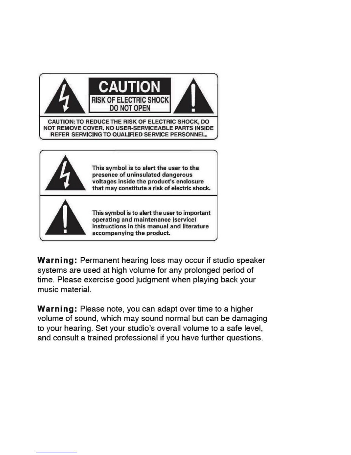
IMPORTANT SAFETY INSTRUCTIONS
Page 5
Page 6

1. Read Instructions.
2. Keep these Instructions.
3. Heed all Warnings.
4. Follow all Instructions.
5. Do not use near water.
6. Clean only with a dry cloth.
7. Do not install near any heat sources such as radiators, heat registers, stoves, or other
apparatus that produce heat.
8. Unplug this apparatus during lightning storms or when unused for long periods of time.
9. Refer all servicing to qualified service personnel. Servicing is required when the apparatus
has been damaged in any way, such as a power-supply cord or plug is damaged, liquid has
been spilled or objects have fallen into the apparatus, the apparatus has been exposed to rain
or moisture, does not operate normally, or has been dropped.
10. The system must be placed on a firm, level surface where it is not exposed to dripping or
splashing liquids.
11. Do not place flammable material above or beneath the AMC.
12. Before making connections to a Blue Sky AMC, ensure that the power is off and other
components are in mute or stand-by mode.
13. Make sure all cable terminations are of the highest quality, free from frayed ends, short
circuits, or cold solder joints. Be especially careful when connecting to terminals marked which
may have hazardous voltages on them during operation.
14. Allow adequate ventilation for the rack.
15. THERE ARE NO USER SERVICEABLE PARTS INSIDE A BLUE SKY AMC
Page 6
Page 7
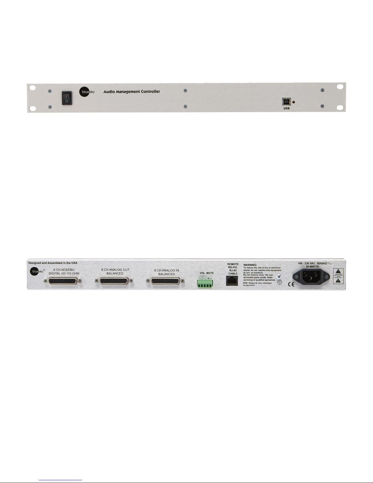
AMC FRONT PANEL
POWER Switch – Turns AMC on and off.
USB 2.0 Connector – used for updating firmware in the AMC rack and the AMC Control program.
STATUS / POWER LED – Indicates the AMC is powered. When flashing indicates internal
microcontroller is operating normally.
AMC REAR PANEL
1.POWER
The AMC has switching power supplies that operates on 100-230 VAC 56/60 Hz. No voltage
change switch required. Standard IEC 3 pin power connector.
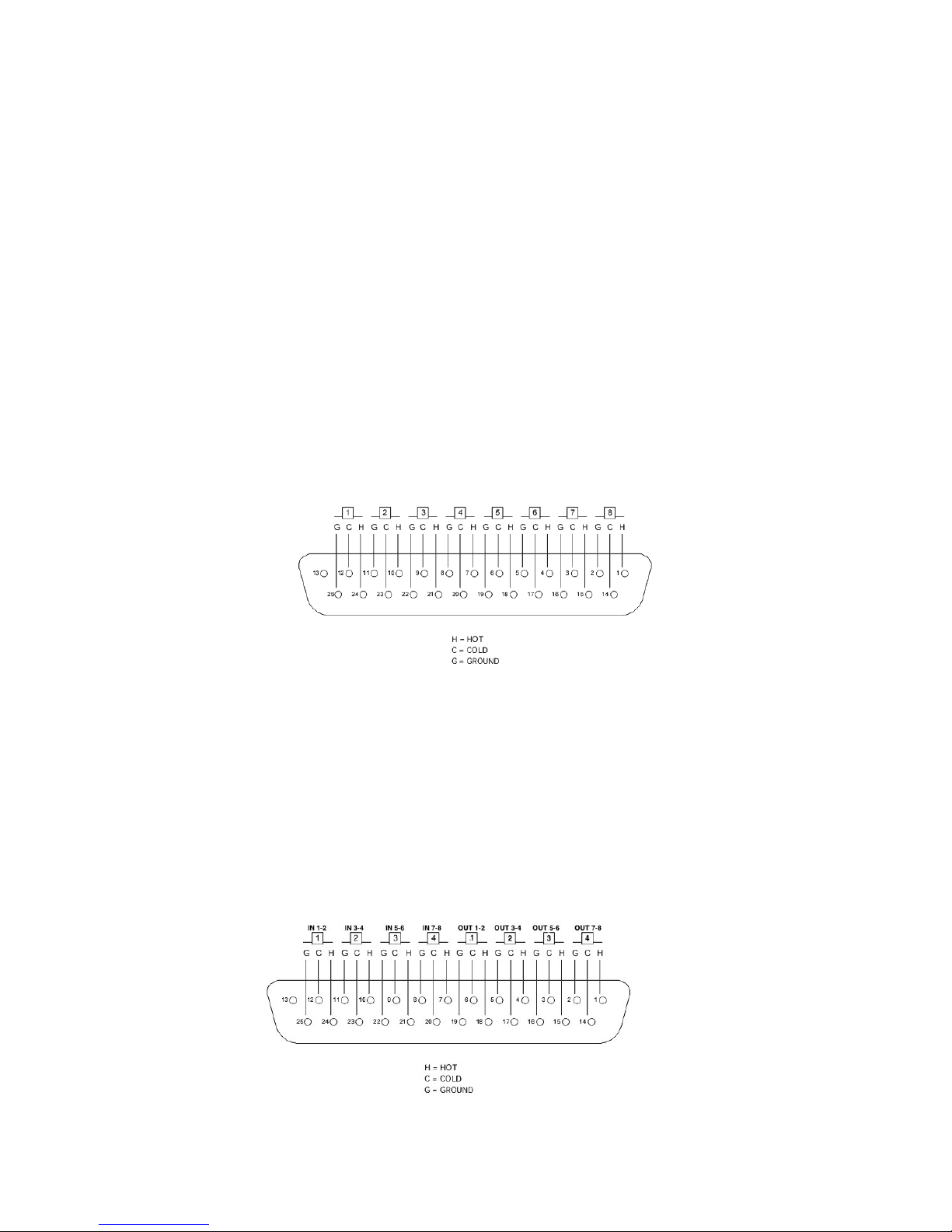
2.CHANNEL ASSIGNMENTS
The AMC I/O connections use DB25 connectors wired to the TASCAM/ Avid protocol for both
analog and digital. These DB25 cables are not supplied.
The channel assignments are SMPTE standard
1. Left
2. Right
3. Center
Page 7
Page 8
4. LFE
5. Left Surround
6. Right Surround
7. Left Rear
8. Right Rear
The channel assignments match the labels on the remote.
However, these channels labels are for reference only. Any channel can be used for any purpose
desired. The only exception is the LFE channel which includes the bass management filters. Since
these filters can be disabled (using the AMC Control Software), the LFE channel can be
reconfigured as a standard channel like the others.
3.ANALOG I/0
The analog inputs and outputs are balanced with a switchable maximum level of +12/+24 dBu.
Both analog and digital outputs are active irrespective of whether the inputs are digital or analog.
4.DIGITAL I/0
The digital inputs and outputs are AES/ EBU 110 impedance transformer isolated I/O. The digital
inputs have built-in 140 dB dynamic range sample rate converters, which convert any digital input
to the native sample rate. The internal sample rate can be set as a global parameter to 48 kHz or
96kHz through the menu on the remote. Changing the sample rate will reset the rack unit and
restart at the new sample rate.
Page 8
Page 9
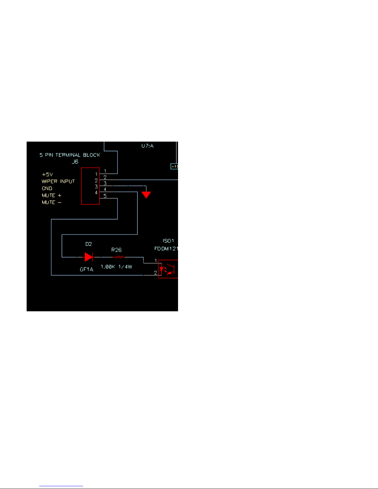
EXTERNAL MUTE INPUT
The green barrier strip has an external mute input, which allows an external switch or 5 V trigger to
mute the entire system. This is normally used for talk-back muting.
The mute input is opto – isolated to prevent ground loops when using an external supply. To use a
switch, connect the normally open switch across pins 1 and 4 and connect a jumper wire between
pin 4 and pin 5 n 3. Close the switch to mute the AMC and open it to unmute the AMC.
To use an external +5 V trigger to mute the rack, connect the voltage across pin 4 and pin 5. A +5
V signal will now mute the rack
REMOTE CABLE
The cable between the remote and the rack unit is a standard Ethernet Cat-5/6 UTP cable with
RJ–45 connectors.
However the signal protocol between the remote and rack is RS-232 not Ethernet.
The remote cable has been tested to 50 ft.
Warning: Do not plug the remote or rack unit into an Ethernet port. It was not designed for this,
and doing so may damage the port or unit.
Page 9
Page 10
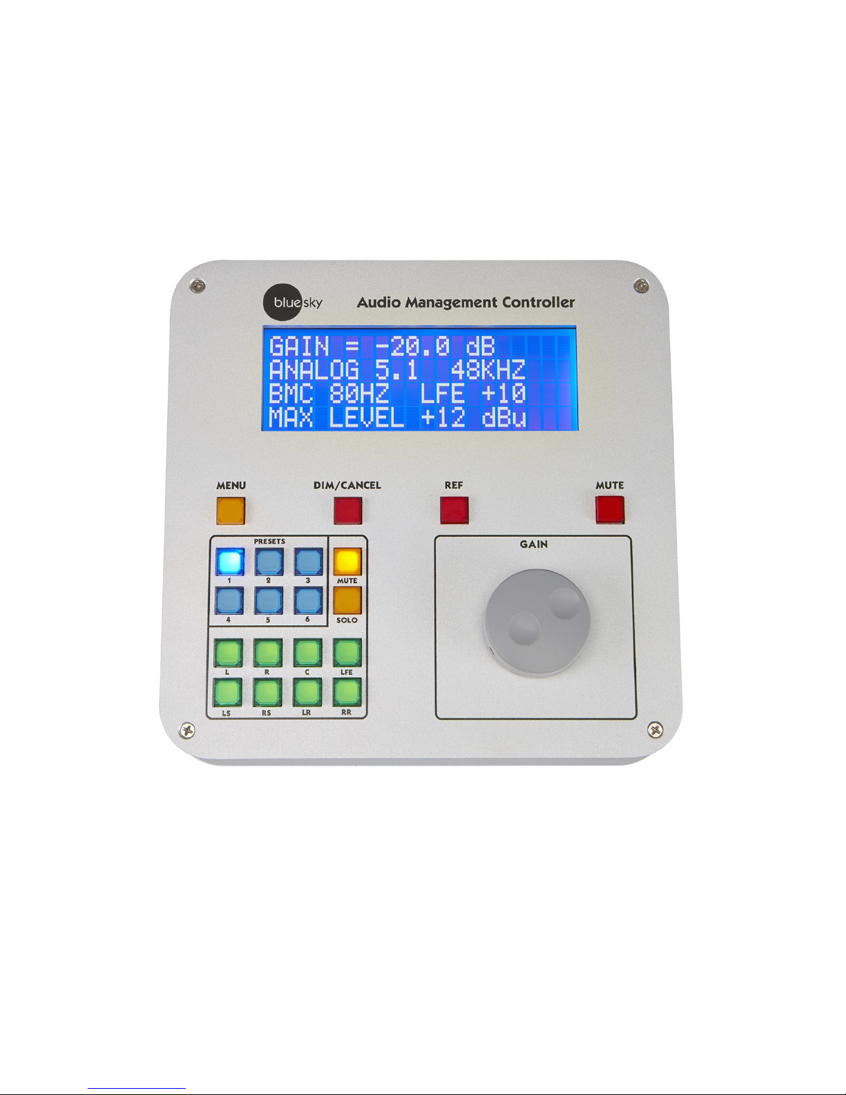
THE AMC REMOTE
FRONT PANEL
GAIN – changes the system gain in 1.0 dB increments . Also used to scroll through the menus and
change parameters.
MUTE – mutes all channels, both digital and analog
REF – sets the system gain to a user defined reference level. The default setting is -20 dB. The
default setting can be changed utilizing the remote menu or the AMC Control Software.
Page 10
Page 11
DIM/CANCEL – reduces the current system gain by the DIM value. The default setting is -10 dB.
The default setting can be changed utilizing the menu or the AMC Control Software. The
DIM/CANCEL switch is also used to exit the menu mode
MUTE MODE – the Solo/ Mute channel buttons operate in mute mode. Switching between Solo
and Mute modes clears all solo/mute buttons
SOLO MODE – the Solo/ Mute channel buttons operate in a Solo Mode. Switching between Solo
and Mute modes clears all solo/mute buttons.
SOLO/MUTE – Solo’s or Mutes that channel. Solo buttons can now be pressed in unison. For
example if you want to solo L, C, R. so can press those buttons all at once.
PRESETS – loads the preset.
MENU – allows a limited number of parameters to be changed on a preset. When exiting the
menu mode, the changed parameters are automatically stored in flash memory.
REMOTE MENU LOCKOUT- Access to the full menu can be restricted by requiring the user to
enter a 4 digital access code. If this feature is activated, whenever the menu button is pressed, the
user will have to use the preset buttons to input the correct 4 digital code to access the full menu.
A limited user menu can be access by hitting the menu button again. This feature can be turned on
or off and the access code changed using the AMC control software remote code.
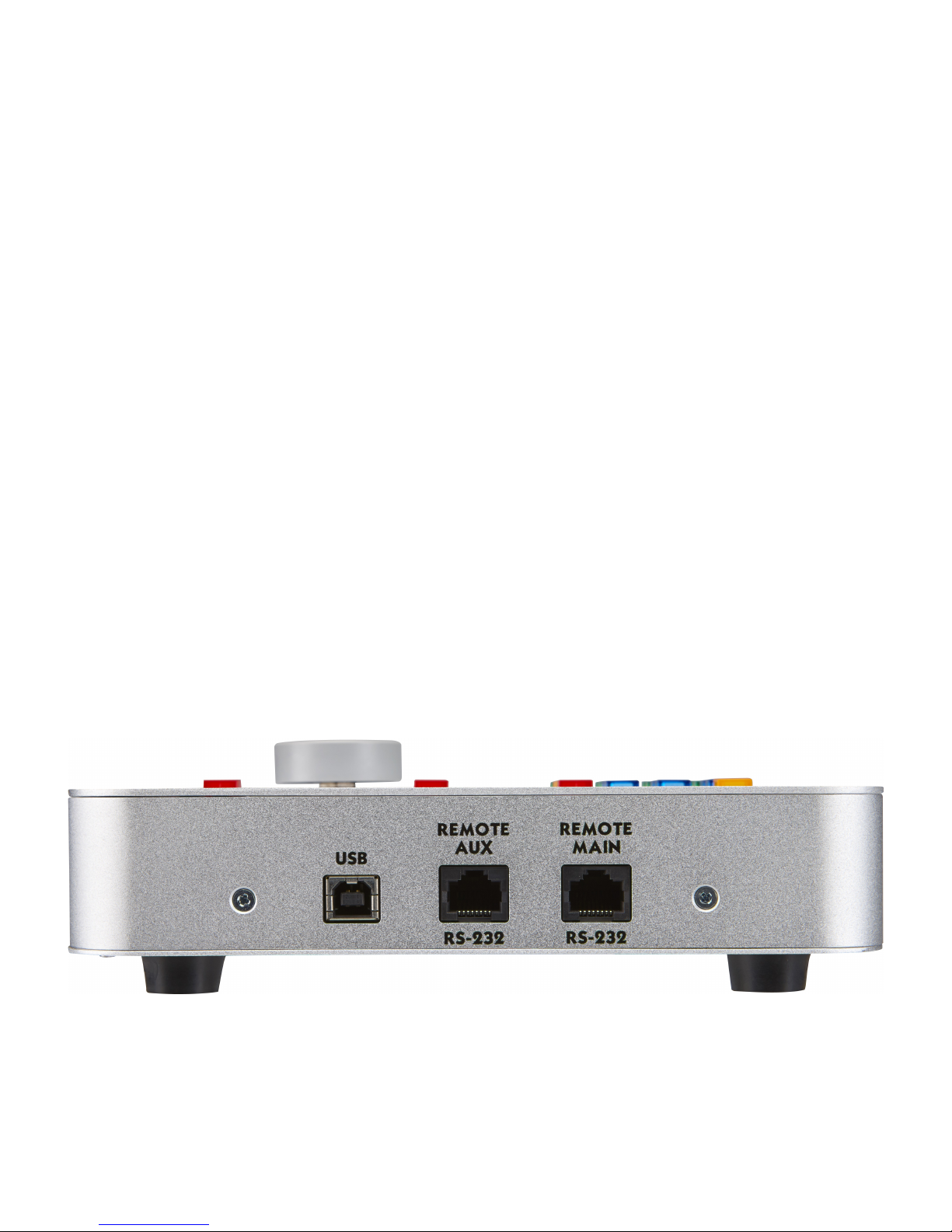
REAR PANEL
USB 2.0 CONNECTOR - used for firmware updates to the remote
REMOTE MAIN RS232 - Connects the Remote to the AMC rack
Page 11
Page 12

REMOTE AUX RS232 - Connects the remote to a 2nd AMC rack for 16 channel operation
THE MENU
Menu Switch – enters the menu mode and switches between scroll and parameter modes.
In the Scroll mode, the gain control “scrolls” through the menu items.
In the Parameter mode, the gain control changes the selected parameter. To switch between
modes, tap the menu key. The current mode is displayed at the bottom of the display.
Dim/Cancel switch - exits the menu mode and stores the changed values in the current preset.
Preset Buttons – when the remote lock out is on, used to input access code.
An example of using the MENU to change the left calibration to +3 dB.
1. Tap the menu switch.
2. Rotate the gain control to cycle through the menu items to left calibration.
3. Tap the menu switch to enter parameter mode.
4. Rotate the gain control CW or CCW until the display reads +3.0 dB.
5. Tap the menu key to go back to scroll mode.
6. Tap the dim/cancel switch to exit the menu and store the preset.
7. To change multiple items, follow 1-5 on each parameter and then hit the dim / cancel key
when you have completed all your changes.
MENU ITEMS
1. Channel Calibration – sets the output gain offset for the selected channel. Used to balance
channel levels.
2. Channel Delay – sets the time delay for the selected channel. Channel delay is used to
time align each speaker to compensate for the unequal distances between the listener and
the speaker. For example, a subwoofer is usually farther away from the listener than the
front speakers, so the sound from the subwoofer arrives later than the sound from the front
speakers. In this case you would add additional time delay to each of the front speakers to
time align with the subwoofer. The time delays of each speaker can be measured using the
Page 12
Page 13

AMC Control software and the optional recommended measurement microphone and USB
audio interface. (See the section on additional equipment you will need, below.)
3. Lip Sync delay – Many video displays have video processing delays which can cause the
audio to be out of sync with the picture. To compensate for video delay, an overall audio
time delay can be added to re-synchronize the audio with the picture.
4. Ref Gain – sets the system gain when Ref button is pressed
5. Dim Gain – sets the gain reduction when the DIM button is pressed
6. +12/+24 analog max level switch – Some studio monitors are high gain devices that have
a nominal input level of around -10 dBu, and not +4 dBu. This switches the gain structure to
+12 dB to optimize the signal to noise ratio. Only affects the analog inputs and outputs.
When using digital IN and analog OUT, this parameter affects the maximum output level of
the analog output.
7. Channel pink noise – Generates a low level pink noise signal on the digital and analog
outputs of the selected channel; The pink noise signal is mainly used to trace down output
channel wiring or to verify the AMC is outputting a signal.
8. Restore to factory defaults - clears all entered preset data and restores the factory default
presets, which include the default target curve setup. Follow the prompts on the screen.
9. System rate rate – selects either 48 or 96khz as the system sample rate. Changing the
sample rate will reset the system, so it is recommended that the user exit the AMC control
software, because a reset will interrupt the USB connection.
10.Digital input Lock Status – indicates that the digital input is locked to a valid digital stream
11. Bass Management ON/OFF- If bass management is turn off, all crossovers are disable
except for the LFE filter.
12.SPL Display Offset Adjustment – adjust the measured dBSPL to the current system
gain. The default is -20 dB = 85 dBSPL. See Calibrating the System to Display dBSPL for
more information.
13.Display dBSPL On/Off – turns dBSPL display on or off.
14.EQ Filter Bypass - When On bypasses all systems EQ including graphic equalizer and
free filters. Does not affect actual EQ values.
USER MENU ITEMS - When the remote is locked, the user has access to REF gain, DIM gain,
PINK noise, the digital input status screen, Bass Management On/Off, and EQ Bypass.
Page 13
Page 14

QUICK SETUP AND USE
The AMC comes with six default which are a mix of digital and analog.
Any preset can be reconfigured to analog or digital or a mix
The display has a short description of the presets. These presets can be modified on a limited
basis using the menu on the remote or completely reconfigured using the AMC Control Software.
1. Connect Audio I/O cables to the AMC and your speaker system.
2. Connect AMC Remote to AMC Rack using supplied Cat 5/6 cable.
3. Connect power cable to AMC Rack.
4. Turn on Rack AC power switch.
5. Wait until front panel LED is flashing and remote mutes.
6. Power-up your speakers.
7. Hit mute button to cancel mute.
8. Enter menu and scroll to Pink Noise.
9. Hit Menu button to switch to parameter mode.
10.Scroll through pink noise channels to verify audio is coming from correct speakers.
Note: The level will be low.
11. Hit Menu to return to Menu scroll mode.
12. Hit Dim/Cancel to return to normal operation.
Page 14
Page 15

UPDATING THE FIRMWARE
DIFFERENCES BETWEEN UPDATING IN WINDOWS AND OS X
The only differences between updating using Windows or OS X is that with Windows you are
required to use an installer to install the firmware updater on your computer. With OS X , the
installers are apps that are self contained.
The firmware in both the remote and rack can be updated through the USB ports and the using the
Blue Sky Firmware Tool. There are separate updateras for the Remote and Rack.
UPGRADING THE FIRMWARE IN THE AMC RACK
NOTE: Different versions of the AMC control software require firmware version numbers matching
the AMC control software. For example, AMC control firmware 5.05 requires firmware version 5.05
be installed in the remote and rack. Letter versions modifier, like 5.05 B, will all work with AMC
Control software of the same base number.
Note: The firmware can only be updated when the rack is powered down.
1. Install the Blue Sky AMC RACK Firmware X.XX update tool. The
installation tool will create a Blue Sky in the Program Files (0x86) sub-directory and
install the update program and the new hex file in that directory.
2. If you get a message that the program requires Elevation and will not run, right click on
the installer and click Run As Administrator.
3. Power down the AMC RACK and plug-in the USB cable. If this is first time you've
connected the AMC Rack to your computer you may get a message that the computer
is installing drivers for the USB interface. Wait until that completes and the front panel
LED flashes a couple of times a second.
4. Start the program and the dialog box will show
BLUE SKY
AMC RACK BOOTLOADER REV 1.00
and the currently installed firmware.
5. If the dialog windows says
BLUE SKY
AMC RACK REV x.xx
Application unable to communicate with the device
Power off the unit, disconnect the USB cable, and plug the cable back in and restart
the program.
Page 15
Page 16

6. Hit the UPDATE FIRMWARE BUTTON
7. The updater will update the firmware and read the new firmware version.
8. Close the program, disconnect the USB cable and you are done
UPGRADING THE FIRMWARE IN THE AMC REMOTE
Note: The firmware can only be updated when the remote is disconnected from the rack or the
rack is powered- down..
1. Install the Blue Sky AMC Remote Firmware X.XX update tool. The
installation tool will create a Blue Sky in the Program Files (0x86) sub-directory and
install the update program and the new hex file in that directory.
2. If you get a message that the program requires Elevation and will not run, right click on the
installer and click Run As Administrator.
3. Disconnect AMC Remote and plug-in the USB cable. If this is first time you've
connected the AMC Remote to your computer you may get a message that the
computer is installing drivers for the USB interface.
4. Start the program and the dialog box will show
BLUE SKY
AMC Remote BOOTLOADER REV 1.00
and the currently installed firmware.
5. If the dialog windows says
BLUE SKY
AMC Remote REV x.xx
Application unable to communicate with the device
Power off the unit, disconnect the USB cable, and plug the cable back in and restart
the program.
6. Hit the UPDATE FIRMWARE BUTTON
7. The updater will update the firmware and read the new firmware version.
Close the program, disconnect the USB cable and you are done
Page 16
Page 17

THE AMC CONTROL SOFTWARE
The AMC Control Software is available in two versions One is 32 bit Windows program that will run
on both 32 and 64 bit versions of Windows 7, 8, and 10. The second is a OS X version that will
run on Yosemite, EL Captain, and High Sierra. This program and is intended for use only with the
Blue Sky AMC and will not run without the AMC is connected to the computer by USB.
Both versions of the AMC Control software are available for download. Contact Blue Sky for a
download link.
INSTALLING THE AMC CONTROL SOFTWARE IN WINDOWS
Download the setup program and save it to your computer at a location where you can find it.
Double-click of the setup program to install it. The installer will create a folder under the program
files (0x86) called Blue Sky and install the program in that folder.
INSTALLING THE AMC CONTROL SOFTWARE IN OS X
Download the zip file and unzip it to your desktop or application folder.
RUNNING THE PROGRAM
Turn on the AMC and wait unit the red LED on the front of the AMC is flashing approximately once
every two seconds and the remote mute button is lit..
Plug the USB cable into the front of the AMC. If this is the 1st time you have connected the AMC to
your computer you may see a message that says USB detected, installing software. Wait till the
computer is done and the LED on the front of the AMC goes back to flashing.
If everything is connected you should see the Main Screen:
Page 17
Page 18

THE AMC CONTROL MAIN SCREEN
When using the USB interface, the AMC rack and the software are linked so preset changes and
parameter changes made on the remote or by the AMC program show on both. The remote update
may lag behind the software by a couple of seconds.
NAVIGATING AROUND THE INTERFACE
The blue boxes represent items that are activated when clicked with your mouse. In some cases
clicking a blue box will initiate an action. In other cases the box will open up another screen.
The black boxes with white text represent parameters that can be entered directly using the delete
key, the backspace key, numerical keypad and the enter key.
The check boxes (square) or radio button ( round) represent an either/or setting. For example, if
you click the +12dBu Max, the +24dBu Max button is turned off
Master Gain - displays the current master gain of the AMC. This value is automatically updated if
the gain control is moved, or if reference and/or dim gain are selected.
dBSPL – displays and edits current dBSPL at current Master Gain setting. This values tracks the
Master Gain setting. This value is stored with each preset so when a single AMC is used with
multiple speaker setup, each setup can have it own reference. If the DISPLAY dBSPL box is not
checked, this box is not visible.
Page 18
Page 19

DISPLAY dBSPL – turn the dBSPL display on and off.
Reference Gain- displays the current reference gain setting. The reference gain for this preset can
be modified directly by typing in the new value in the box. This value will also be updated if the
reference gain setting is changed through the remote
Dim Gain- displays the current dim gain setting. The dim gain setting for this present can be
modified directly by typing in value in this box. This value will also be updated if the dim gain
setting is changed through the remote
System Sample Rate- shows the current internal sample rate of the AMC. This value can only be
changed through the remote.
Loading a preset – loads a preset Click on the blue buttons in the upper left hand corner of the
Presets can also be loaded by hitting a button on the remote, which will be indicated on the AMC
screen.
Saving a preset – saves the currently loaded preset to the AMC rack. A loaded preset can be
saved to itself or to any other preset location.
Preset display – these 3 lines of text are what will appears on the remote when a preset is loaded.
Each line of text can be changed directly using the keyboard.
Remote Access Code - a 4 digit access code for the remote menu . Since the preset buttons are
used to enter the code, only digits 1 to 6 are allowed.
Restrict Remote Menu Enable- when checked requires the user to enter the correct 4 digit code
to access the full Remote Menu.
SRO- opens up the speaker room optimization panel.
Save Presets to File- pressing this button will open up a dialogue to save all presets to a text file.
The text file is in a human readable form and has all the parameters the makeup the preset.
Load Presets From File-loads a previously saved preset file.
Analog +12dB/ +24 dB Max switch – Switch the analog IO between +12 and +24 dB maximum
output level.
Digital in lock status box – shows whether a digital input has a valid digital signal attached.
16 In 8 Out Mixer- opens up the cross mixer panel (see CROSS MIXER )
Base Management- opens up the base management panel ( see Base Management)
EQ buttons- opens up the channel equalizers(see EQ).
Channel Calibration – sets the relative balance between the channels. These values can be
Page 19
Page 20

entered directly in the boxes or entered automatically using the SRO procedure. See the Speaker
Room Optimization (SRO) section below for more information.
Channel delay in milliseconds - sets the individual time delay for each channel output and is
used to time align the speakers.
Lip sync delay in milliseconds- set some master time delay for all channels both digital and
analog and is used mainly match audio to picture .
Analog gain dB - master offset for the analog outputs and is normally used when operating with
digital in and analog out.
Digital gain dB - master offset of the digital outputs and is normally used when operating analog
in to digital out
Grey preset setup buttons- the buttons along the bottom of the screen, set up the loaded preset
to a common set up values.
Page 20
Page 21

CROSS MIXER
The cross mixer screen – when you click on the cross mixer box on the main screen it will
open up a new screen as follows.The cross mixer screen shows how each inputs (analog
and digital) are routed to each output. The gain can be entered directly in the box or to mute
an input type in “off” or ”OFF” in the box. In addition to entering gain values directly in the
boxes, you can now double click on the box to set the gain 0,-3 and OFF. The LFE box cycles
from 10, 0, to OFF.
If bass management is turned OFF (see Bass Management), the non - LFE feeds to the LFE
output channel will be disabled and displayed in red indicating that they cannot be changed. If in
this state, the user will have to go to the base management screen and turn bass management ON
before these values can be edited.
The gray buttons along the right side configure the mixer to common settings. These buttons only
program the cross mixer and do not affect EQ or crossover values.
Note: In some cases, as in theatrical movies releases, the surrounds are 3 db down from the main
speakers. If that is the case, you also want to drop the surround feeds to the subwoofer. For
example, you would set LS IN to LS OUT at -3 dB, and then also set LS IN to LFE out at -3 dB.
To go back to the main AMC control screen click the X in the upper right-hand corner of the screen
Page 21
Page 22

BASS MANAGEMENT
The blue bass management button will bring up the following screen.
The bass management screen shows the bass management settings for each individual channel
and the graphs show the resulting frequency response of the electrical crossovers without the
effects of EQ.
The gray buttons along the bottom of the screen preset the crossovers to common values.
For each channel, the type of filter employed and the cutoff frequency of that filter can be selected.
The filter labels have the following meanings:
Bypass No filter in circuit
LP2 2nd order 12 dB/oct low pass filter with a Q of .707
LPBW4 Two LP2 filters in series resulting in a 24 dB/oct low pass
LP6 6th order Chebyshev 36 dB/oct filter (typical LFE Filter)
HP2 2nd order 12 dB/oct high pass filter with a Q of .707
HPBW4 Two HP2 filters in series resulting in a 24 dB/oct high pass
For the feeds to the subwoofer, you have a choice of Bypass, LP2, LPBW4 and LP6 filters.
In addition to the low pass filters for the subwoofer, there are auxiliary high pass filters that can be
used on each channel feed to the subwoofer. The choices for the high pass filter are Bypass, HP2
Page 22
Page 23

and HPBW4.
Normally these filters are used, when using bass management where you don't want the signal
sent to the subwoofer to go down to 20 Hz.
For example, if you're doing editorial work on a soundtrack that is being mixed for a theatrical
release, a bass managed system mix can result in too little bass when played back on the
theatrical system. This is because front speakers in a theatrical system typically only go down to 40
Hz.
So to get better a translation, you could employ a 40 Hz HP2 or HPBW4 high pass filter on the left,
center, and right channels.
The same holds true for surround speakers. In a typical theater setup the surrounds typically do
not go down below 60 Hz. Again to get better translatability you may employ a 60 Hz high pass
filter on the surround channels.
The AMC system also includes a high pass filter for the each channel.
These filters are not in the subwoofer feeds but on the individual channels. The choices are
Bypass, HP2 or HPBW4.
The bypass setting is used when you're not using bass management.
HP2 or HPBW4 are used depending on the actual speaker attached to the channel. If the speaker
is made for bass management, (IE Blue Sky SAT6D) then you use a HP2 set to 80 Hz. If however,
if the attached speaker is a full range monitor that may go down to 50 or 40 Hz, you'd use a
HPBW4 to get a better blend with the subwoofer.
Bass Management on/off - turns bass management on and off. When bass management is OFF,
all crossovers are disabled except for the LFE filter. When in this mode, none of the filters on the
screen can be modified which is indicated in red. To modify any of the filter settings make sure
bass management is turned ON.
Grey Preset buttons The gray buttons along the bottom of the bass management screen are
presets for common bass management setups. Note: these presets only affect values on the base
management screen and do not program the cross mixer.
Page 23
Page 24

EQ
1/3 OCTAVE EQ
31 band EQ- the cut and boost of any band on EQ can be changed by moving the slider with the
mouse. The frequency response will automatically reflect an EQ changes
EQ optimize button sets whether the 1/3 octave EQ is used for optimization in the SRO process
UNASSIGNED CHANNEL FILTERS
There are 8 uncommitted filters per channel that can be used for additional EQ beyond the 1/3
octave equalizer.
Optimize- sets whether the filter is used in the SRO optimization process
Active- selects whether the filter is in the signal processing path or bypassed
Filter type- a drop-down menu to select various types of filters available.
Page 24
Page 25

Frequency - sets the cutoff frequency of the filter. This value can be changed by typing a new
frequency in the box or by double clicking the box and clicking any point on the graph
.
Q- sets the q of the filter , which can be changed by typing a new value in the box. The value can
also be changed by double clicking the q edit box. A slider control will appear allowing Q to be
adjusted in real time. Double click the gray area of the slider control to close it.
Boost -sets the cut or boost of the filter. The boost can also be changed by double clicking the
boost edit box. A slider control will appear allowing boost to be adjusted in real time. Double click
the gray area of the box to close it.
Note: Boost setting have no affect on LP2 or HP2 filters.
Max filter cut DB - sets the maximum amount of cut used in the SRO process, This setting
affects the 1/3 octave EQ and uncommitted filters
Max filter boost DB- sets the maximum amount of boost used in the SRO process
Save to Presets - saves the displayed EQ setting to any preset location.
This feature is commonly used to copy EQ data from preset to another.
Clear EQ - clears all EQ values on that preset .
Display EQ channel - switches between channel EQ's without having to close out the screen and
open another window.
Bypass All EQ Button – This button bypassed all EQ setting without altering any EQ settings.
Useful for auditioning trial eq values.
Page 25
Page 26

TARGET CURVES
The target curve represents the ideal response of the speaker after optimization. To review or
adjust the Target curve for any speaker, open the SRO screen and click on the target curve you
want to modify. Starting with Rev 5.05 all target curves are saved in the AMC Rack with the
presets.
The target screen contains the following items:
Target Filters – the target filters are used to construct the target curves. In many situations the
target filters are automatically selected from the values entered in the bass management panels,
which is the default setup for Blue Sky speakers using bass management.
If the target curves are not appropriate for your application, you can construct a custom target
curve using any or all filters.
Note: Not all the values in the boxes are used for all filters. For example, the slope, dB/oct, and
Q are not used for HPBW4, etc. If you change a value and there is no change in the graph, that
parameter is not used. Also, the HP Shelf and Low Pass Shelf are not “real” shelving filters but
special target filters. "Real" shelving filters have slopes that are multiples of 6 dB /oct. For an
example, in post-production, near-field monitors used for editing may require a 3-dB/oct roll-off
above 4 kHz so the sound matches speakers on the dubbing stage. Although a 3 dB target curve
can be constructed with conventional filters, it may take 6 or more separate filters and a lot of
experimentation to get the target curve you want. However, with the special target shelf filters, it is
much easier.
Page 26
Page 27

Target Scale Low and High Freq – the software uses the frequencies between these to calculate
the avg. microphone level and this is used to adjust the target curve so it “floats' with the drive
level. These frequencies are usually selected to be in a flat portion of the measured curve.
Low and High Target Freq – the optimizer only works in the frequency range located between
these two points. Any frequencies outside this range are excluded from the optimization process,
allowing you to limit the range of optimization. For example, you may not want to try to optimize a
subwoofer flat to 20 kHz. Or, for instance, you might only want to optimize for a narrow area
between 100 Hz to 500 Hz. it's best to keep the low target frequency at the -3 db point of the
measured speaker. Trying to correct below this point usually leads to excessive boost at low
frequencies due to noise floor issues.
GATE TIME MS – the AMC uses the maximum length frequency (MLS) method to measured the
impulse response of each speaker. The impulse response is converted into frequency response by
using a FFT with a gated time window time. The length of the gate control the low frequency limit of
the measurement.
Grey preset buttons- the gray buttons along the bottom after optimization of the screen set the
target curve for many common setups
Note:
All frequencies values can be set by directly entering frequencies enter directly or by double
clicking the box and clicking any point on the frequency graph.
Page 27
Page 28

SPEAKER ROOM OPTIMIZATION (SRO)
OVERVIEW
SRO is a system for measuring the acoustic response of a speaker system and correcting the
speaker system to a target frequency response.
Note: if a valid USB audio interface is not found the measurement function will be disabled.
The measurement portion of SRO uses a special noise signal called a maximum length sequence
(MLS). Unlike white or pink noise, MLS signals have unique properties that allow them to be used
to calculate the impulse response of a speaker, which contains the complete frequency, phase, and
time response of the speaker.
Once, you have obtained the impulse response, with the use of a fast Fourier transform (FFT), it is
easy to calculate the frequency response of the speaker. Once the frequency response is
obtained, the next phase is optimizing.
During the optimization process, the uncorrected frequency response of the speaker is compared
against a desired frequency response called the target curve.
The target curve can be an “X” curve, a flat frequency response curve or an arbitrary curve that the
user created.
The software then compares the speaker response against the target and generates an error
value. The error value is a quantitative measure of how well they match. The larger the error the
worst the match.
The software uses filters (like a 1/3 octave equalizer) to correct the frequency response of the
speaker to lower the over all error (IE. a better match).
It does this using a genetic mutation algorithm called BOO, which generates thousands of different
EQ settings and determines which one gives the best match to the target curve
Once BOO picks the best match, the user has the option of accepting it or tweaking manually form
there.
One last point. The SRO program will correct many frequency response problems but it does have
limitations. It will not give repeated reliable results if the room is too noisy. It will not make a poorly
designed room with poor acoustic treatment sound like a well designed room.
Page 28
Page 29

ADDITIONAL EQUIPMENT YOU WILL NEED
The Blue Sky SRO program uses an inexpensive USB audio interface and measurement
microphone to generate test tones and measure the frequency response of the speakers attached
to the AMC.
You will need the following:
1. Measurement microphone - the recommended choices are the Dayton Audio EMM-6 or
Behringer ECM8000. However, it is possible to use other high quality other measurement
microphones, but the above are known to work fine, and are relatively inexpensive.
2. USB Interface - the ART USB Dual PRE is the recommended USB audio interface used for
measurement. It is an inexpensive system with dual microphone preamps, dual audio
outputs, operates at 48 kHz and has a phantom power supply for the measurement
microphones. It uses the built-in driver for windows.
3. Microphone stand.
4. 2 - 1/4" TRS- to XLR male microphone cables. One can be short (1.5 ft) for the loop back
connection and one should be long enough to connect to the speaker.
5. XLR microphone cable for the measurement microphone
SETTING UP THE ART USB DUAL PRE in WINDOW
1. Plug the short TRS to XLR male cable from the Dual Pre right output to the Dual Pre right
microphone input.
2. Set the mix fader to computer (Max CW).
3. Set the output level straight up (12 O'clock).
4. Press the phantom switch to on.
5. Press the power to on.
6. Plug the measurement microphone into the Dual Pre left microphone input.
7. Set the left gain to 16.
8. Set the right gain to 1.
9. Plug the USB cable from the computer into the ART USB interface on the back. If the 1st
Page 29
Page 30

time the device is connected to the USB port you'll get a driver installation message.
10.Setup the ART as the default playback device and set its Playback properties. Windows
Control Panel-> Sound-> Playback ->USB Audio CODEC -> Set Default Properties>Advanced-> 16 bit, 48000Hz (DVD Quantity) -> OK.
11. Setup the ART Dual Pre as default recording device and set its recording properties.
Windows Control Panel-> Sound->Recording->Microphone USB Audio CODEC ->Set Default
Properties-> Listen-> Uncheck ->Listen to device
Properties-> Levels-> 100.
Properties-> Advanced-> 2 channel 16bit, 48000 Hz ->OK.
Note: If you disconnect the ART Dual Pre from your computer, you may have to go through this
process again.
SETTING UP THE ART USB DUAL PRE IN OS X
1. Plug the short TRS to XLR male cable from the Dual Pre right output to the Dual Pre right
microphone input.
2. Set the mix fader to computer (Max CW).
3. Set the output level straight up (12 O'clock).
4. Press the phantom switch to on.
5. Press the power to on.
6. Plug the measurement microphone into the Dual Pre left microphone input.
7. Set the left gain to 16.
8. Set the right gain to 1.
9. Plug the USB cable from the computer into the ART USB interface on the back. If the 1st
time the device is connected to the USB port you'll get a driver installation message.
10. Go to System Preferences ->Sound and Verify the USB Audio CODEC is listed in the Input
and Output Panel.
11. Go to Applications ->Utilities-> Audio MIDI Setup
USB Audio Codec ->Output-> Format 48000 2ch-16 bit Integer
Page 30
Page 31

Ch->Volume-> Both 0 dB
USB Audio Codec ->Input-> Format 48000 2ch-16 bit Integer
Note: If you disconnect the ART Dual Pre from your computer, you may have to go through this
process again.
GUIDELINES ON MICROPHONE SETUP
Typical small diaphragm measurement microphones have an omni-directional response pattern
over most of the audio band with a slight narrowing of the pattern as frequency of approach 20 kHz
Most speakers on the other hand, have an omni-directional pattern only at frequencies below
1kHz. Based on these characteristics, here are some general guidelines on setting up
measurement microphones:
1. The height of the microphone should be placed at ear level.
2. Most of the frequency response problems in rooms are related to standing waves
and boundary effects which occur at frequencies below 1KHz, and typically below
200 Hz. If this is the main area the user wants to focus on, the exact aiming of the
microphone to the speakers is noncritical. The mic can be pointed at the speaker, or
at an angle of 45°, or straight up. Many users find that straight up[ gives the
best response.
3. If you're interested in correcting frequencies over the full audio bandwidth, and the
mixing position is within 1m to 2 meters, you should point the microphone towards
the speakers for best results.
4. In larger rooms, where the speakers are many meters away from the mixing position,
the direction the microphone is pointing is less critical, and the recommended
microphone position is pointing straight up.
5. In all cases, if you are unsure of your microphone placement you should do a couple of trial
measurements to see which position is best.
Page 31
Page 32

USING THE SRO PROGRAM (SIMPLE SET UP)
1. Connect the ART USB Dual Pre output to Analog 8 In on the AMC
2. Connect the ART USB cable to the a USB 2.0 port.
3. Using a microphone stand set the measurement microphone at your listening position and
at ear height.
4. Connect the microphone to the LEFT Input on the ART USB Dual Pro. Set the Left Gain
control on to 18.
5. Connect the RIGHT Output of the ART to the RIGHT Input. Set the Right Gain to 3.
6. Connect the Left Output of the ART Dual Pre to the CH 8 analog input on the AMC.
7. On the rear of the ART set the MIX Knob FCW to Computer.
8. On the rear of the ART set the LEVEL knob to 12 o’clock (straight up)
9. On the rear of the ART press the PHANTOM IN.
10.On the rear of the ART press the power switch in
Page 32
Page 33

STARTING THE SRO PROGRAM
Once the AMC Control program is running, click the SRO button in the right hand corner of the
main screen. The following screen will pop up.
This screen shows the current state of the EQ, target filters, measured frequency response and
corrected frequency response of all the channels. Clicking on any of the small graphs will open up
a larger graph.
Measure- measures the selected speakers. You must have at least one speaker selected for the
measure button to be active.
Optimize - Starts the optimization process on the selected the speaker response to the target
curve. You must measure the speaker before the optimize button is active.
Clear EQ - clears the EQ on the selected channels.
USB audio in - shows a compatible audio USB interface input, normally the ART Dual Pre
USB audio out- shows a compatible USB audio interface output normally the ART dual Pre
Page 33
Page 34

MAKING A MEASUREMENT
Set up the microphone and USB Audio Interface first! \
FREQUENCY RESPONSE CURVE
GREEN curve is the measured frequency response.
RED curve is the target response.
BLUE curve is the electrical response of the EQ
Orange curve is the calculated corrected response
The two vertical yellow bars are the target range
AVG MIC LEVEL - measured microphone level. This is the average level between the Target
scale low and high frequency limits.( Green lines on the target curves). The optimum level avg
microphone level is -20 dB >
If the level is low, increase the gain on the remote control. If the measured response is too low, the
noise floor of the room and or the microphone may prevent an accurate measurement.
Normally when optimizing a Blue Sky SAT6D, the remote gain control is set for 0dB.
Page 34
Page 35

BEST ERROR - during optimization, the program calculates deviation from the target curve and
displays an error number. The best error is the closest match so far.
CURRENT ERROR - the current calculated error for this pass of optimization
MEASURED TIME DELAY - measured time delay between the speaker and the microphone in
milliseconds. This includes any processing delays inside the AMC.
OPTIMIZING USING 1/3 OCTAVE FILTERS
1. Set up the desired target curves and the optimization frequency range
2. Select the 1/3 Octave for optimization and maximum and minimum cut and boost to use for
optimization
3. Select and measure speakers you want to optimize
4. Press the Optimize button
5. The program will open a pop-up screen showing the speaker being optimize, the current
results, and the best results so far. The optimization process calculates the least squared
error between the target curve and the corrected frequency response over the range
between the two yellows lines. The program will not try to optimize any filters or areas
outside of the yellow lines. The program will automatically jump to the next speaker when
the program can no longer find a better match. However if you're happy with the current
results you can cancel optimization by double-clicking the blue stop optimization button.
Note - You can stop optimization at any time by double-clicking the Stop Optimization
button.
6. If you are happy with the results, click the SAVE PRESET button (on the Main panel) to
save the EQ value to the flash memory of the AMC.
7. If you are measuring and optimizing more than one speaker, the optimization process will
balance the level of each channel and adjust the time delay to time align the speakers with
each other. Those values will show in the Ch Delay (ms) and Calibration (dB) on the main
AMC control.
OPTIMIZING USING 8 UNASSIGNED FILTERS
The parametric filters are mainly used to reduce peaks in the frequency response or when you
need to match an x curve response. As a general rule it is a bad idea to use parametric filters to fill
in deep dips. Unlike optimizing using the 1/3 octave equalizer, optimizing using the free filter is
more a semi-automatic process.
Page 35
Page 36

1. Define your target curve
2. Measure the speakers.
3. Go to the EQ page, and find the peaks you want to reduce.
4. Uncheck the “OPTIMIZE USING 1/3 OCT EQ” checkbox
5. Select the filters you want to use. IE one peak one filter etc.
6. Then one by one per filter double click the frequency box of the filter and then the peak on
the frequency graph.
7. Go to the Target page and adjust the LOW TARGET frequency and HIGH TARGET
frequency to include the desired frequency band. Because the optimizer will not adjust filter
frequencies outside the Low and High target , include set the low limit below the lowest
peak and the High frequency above the highest peak frequency.
8. Select the frequency range by adjusting the lower and upper target limits (vertical thick
yellow lines).
9. Return to the main screen, click OFF the box Optimize using 1/3 Octave EQ.
10.Activate the number of filters you want to use by clicking the Filter Optimize Box.
11. Press the OPTIMIZE
12.The screen will show the optimization in process with live updates. The optimization process
calculates the least squared error between the target curve and the corrected frequency
response over the range between the two yellows lines. The program will not try to optimize
any filters or areas outside of the yellow lines. However if you're happy with the current
results you can cancel optimization by double-clicking the STOP button. When the
optimization is complete the program will automatically jump to the EQ screens he can
make any manual adjustments that you may desire.
13.If you are happy with the results, click the SAVE PRESET button to save the EQ value to
the flash memory of the AMC.
Page 36
Page 37

To illustrate the process, here is a measurement of a left speaker
There is a broad peak at approximately 450 Hz, that we want to reduce using one parametric filter.
1. We have selected one parameter filter, double clicked on the frequency box and the graph
to the approximate center of the peak. This sets 470 Hz in the frequency box.
Page 37
Page 38

2. Go to the target curve screen and you can see the frequency range is the default 80 to 4 khz
kHz.
3. Double click on the LOW TARGET FREQ and the graph to set the low target to the low end
of the peak.
4. Double Click the HIGH TARGET FREQ and the graph to the high target
Page 38
Page 39

5. Go to The SRO screen and hit Optimize.
Here is the result
Page 39
Page 40

Page 40
Page 41

CALIBRATING THE AMC TO DISPLAY dBSPL
Firmware and software versions 5.13 and above allow the AMC remote to display dBSPL in
addition to system gain. The relationship between system gain and displayed dBSPL is a user
define value that must be manually input after the system is equalized and each channel
calibrated.
To set the correct dBSPL level do the following:
1. Download the Blue Sky Calibration Test Files at
http://abluesky.com/support/blue-sky-calibration-test-files.
2. Complete EQ'ing and optimizing your speaker system including channel calibration.
3. Follow the Blue Sky Calibration instructions and measure the SPL of the center channel at
the listening position.
4. Without changing the Remote Master Gain setting go into the menu and adjust the dBSPL
setting to match the reading of your SPL meter. Alternately, you can directly enter the value
on the AMC Control software.
5. Click the dBSPL Display checkbox.
6. Repeat for other presets if needed.
7. You will have to repeat the procedure, if you make significant EQ or level changes.
Page 41
Page 42

AMC SPECIFICATIONS
Analog Noise Floor -106 dBu / -96dBu (20 Hz - 20 kHz flat) +12/+24
Analog Dynamic Range 118 dB
Maximum Analog Input +12 dBu / +24 dBu
Maximum Analog Output +12 / +24 dBu
Analog THD + N, .002% +4 dBu In (20 Hz -20 kHz)
Digital THD + N .00002% -20 dBFS (20 Hz - 20 kHz)
Digital In Lock Range 44.1 kHz -192 kHz
Frequency Response 10 Hz – 22 kHz +0,-1dB
Lip Sync Delay 0- 176 ms @ 48 kHz
Channel Delay 0 -27 ms @ 48 kHz
Internal Processing Sample Rate 48 kHz / 96 kHz
Input power 90 to 240 V AC 50/60 Hz 42 watts
Chassis 19” rack 1 U high
Note: All specifications are typical and subject to change without notice.
Page 42
 Loading...