

Page 1

Page 1
AUDIO MANAGEMENT CONTROLLER (AMC) MANUAL
Page 2

Page 2
Description
The Blue Sky Audio Management Controller (AMC) is an 8-channel audio DSP platform with both
24-bit digital and analog I/O.
Each channel of the AMC has a sample rate converter (by stereo pair), a 31 band 1/3 octave
equalizer, eight parametric / free assignable filters, individual channel delays, and lip-sync delay.
An 8x8 cross-point mixer allows any input to be mixed to any output.
The flexible bass management system can be customized on a channel-by-channel basis, or
turned-off completely.
The AMC has 6 presets, each of which stores complete setup information, including filter setting,
I/O configuration, delays, etc.
The AMC includes control software that is a PC (Mac in process) application that connects through
the USB port.
The AMC includes SRO (Sound Room Optimization) software which includes an MLS based
measurement system with auto room correction or expert manual mode, correcting the in room
speaker response to a user definable target curve.
Page 3

Page 3
Table of Contents
AMC Features ...................................................................................................................................5
AMC I/O connections .......................................................................................................................6
Analog I/0 ................................................................................................................................. 6
Digital I/0 .................................................................................................................................. 6
External Mute Input .................................................................................................................. 7
Remote cable............................................................................................................................ 8
Quick setup and use ........................................................................................................................8
The AMC Remote .............................................................................................................................9
The AMC Remote / Operation .................................................................................................. 9
The Menu ............................................................................................................................... 10
Menu Items ........................................................................................................................... 11
Firmware Updates ..........................................................................................................................12
Upgrading the firmware in the AMC RACK to the latest version. ........................................... 12
Upgrading the firmware in the AMC Remote to the latest version.......................................... 13
The AMC Control Software ...........................................................................................................14
Installing the AMC Control software ...................................................................................... 14
Running the Program ............................................................................................................. 14
AMC Main Control Panel ..............................................................................................................15
Navigating around the interface.............................................................................................. 15
Cross Mixer ....................................................................................................................................18
Bass Management .........................................................................................................................19
EQ Screen .......................................................................................................................................21
Speaker Room Optimization (SRO) ..............................................................................................23
Overview ................................................................................................................................ 23
Additional equipment you will need ....................................................................................... 23
Measuring and optimizing your speaker system .................................................................. 24
Guidelines on microphone setup ........................................................................................... 25
Setting up the ART USB Dual Pre to use with Blue Sky SRO Software................................. 26
Page 4

Page 4
Setting up the ART USB Dual Pre for use with the AMC SRO .............................................. 27
The SRO Main Screen ...................................................................................................................28
Target Curves ................................................................................................................................30
AMC Specifications .......................................................................................................................32
Page 5

Page 5
AMC Features
o 8 balanced analog inputs and outputs with switchable +12 / +24 dBu maximum levels
o 8 AES 110 ohm digital inputs and outputs, each transformer Isolated
o Burr Brown / TI PCM1792A digital to analog converter with 132 dB SNR
o Burr Brown / TI PCM4222 analog to digital converter with 124 dB SNR.
o Cirrus Logic CS8422 sample rate converter with 140 dB SNR
o National LME49760 op amps, with 55 MHz bandwidth and 20V/us slew rate
o Analog / Digital I/O selectable in pairs.
o Simultaneous digital and analog outputs
o Adjustable analog and digital output offset
o Quad Analog Devices 56 bit fixed point processor
o Digital input sample rate range 44.1 kHz to 192 kHz.
o Internal sample rate 48 kHz or 96 kHz (switchable)
o 31 Band 1/3 octave double-precision digital EQ per channel
o 8 user definable 2nd order double precision digital filers per channel
o 6 user defined presets
o 4 line large lighted high contrast display on remote
o Solo / Mute channel selection buttons.
o Mute, Dim, and Ref gain buttons
o Adjustable channel and lip sync delays
o Adjustable individual channel calibration
o SRO room optimization software
o Firmware updatable through the USB port.
Page 6
Page 6
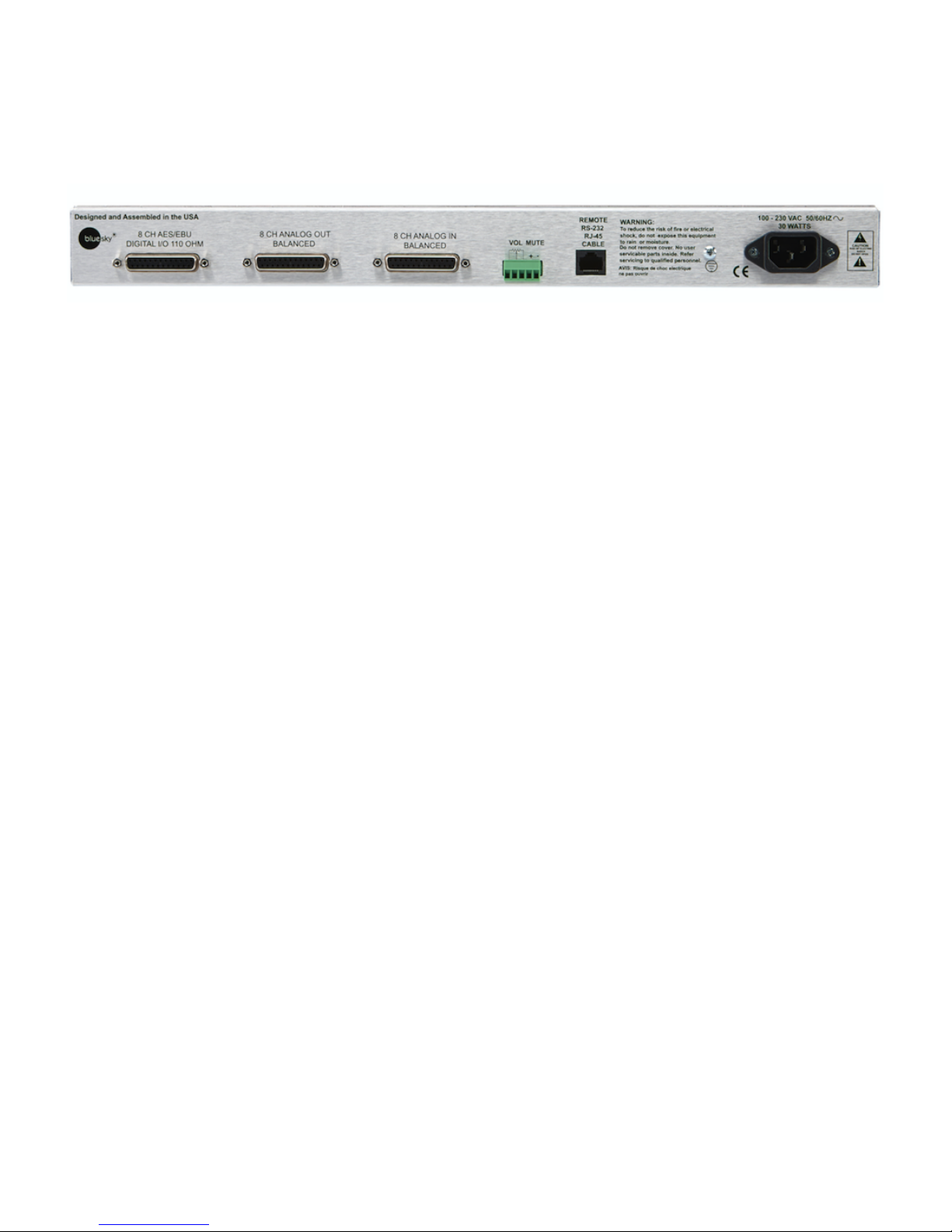
AMC I/O connections
The AMC I/O connections use Tascam DB25 connectors for both analog and digital. These DB25
cables are not supplied.
Channel assignments
The channel assignments are SMPTE standard
1) Left
2) Right
3) Center
4) LFE
5) Left Surround
6) Right Surround
7) Left Rear
8) Right Rear
The channel assignments match the labels on the remote.
However, these channels labels are for reference only. Any channel can be used for any purpose
desired. The only exception is the LFE channel which includes the bass management filters. Since
these filters can be disabled (using the AMC Control Software), the LFE channel can be
reconfigured as a standard channel like the others.
Analog I/0
The analog inputs and outputs are balanced with a switchable maximum level of +12/+24 dBu.
Both analog and digital outputs are active irrespective of whether the inputs are digital or analog.
Digital I/0
The digital inputs and outputs are AES/ EBU 110 ohm and transformer isolated. All digital inputs
have an integrated sample rate converter that automatically converts incoming sample rate to the
internal AMC sample rate. The internal sample rate can be set as a global parameter to 48 kHz or
96kHz through the menu on the remote.
NOTE: Setting the sample rate, 48 kHz or 96 kHz, will reset the AMC rack unit and load the new
sample rate into the software program.
Page 7
Page 7
The digital inputs have built-in 140 dB dynamic range sample rate converters, which convert any
digital input to the native sample rate. The 4 input pairs do not have to be at the same sample rate
or synchronized to a master clock.
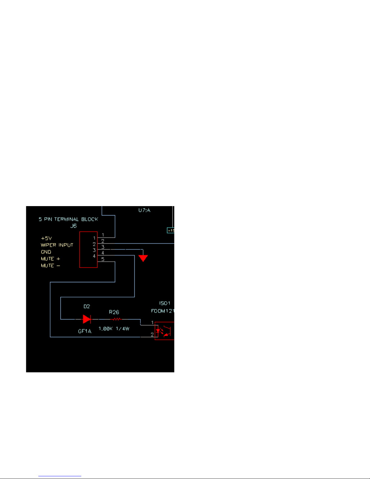
External Mute Input
The green barrier strip has an external mute input, which allows the external switch or +5 volt
trigger to mute and un-mute the entire system. This function is normally used for talk-back muting.
The mute input is opto-isolated to prevent ground loops when using an external supply. To use an
on-off switch, connect the normally open switch from across pin 4 and 5 and connect a jumper wire
from pin 1 to pin 4. Closing the switch will activate mute.
To use an external voltage trigger voltage to mute the rack, connect the trigger source across pin 4
and 5. Applying 5 volts will mute the AMC. Removing the 5 volts will un-mute the AMC.
When the AMC is muted externally, the remote will display the mute status.
Page 8

Page 8
Remote cable
The cable between the remote and the rack unit is a standard Ethernet Cat-5/6 UTP cable with
RJ–45 connectors.
However the signal protocol between the remote and rack is RS-232 not Ethernet. The remote
cable has been tested to 50 ft.
Warning: Do not plug the remote or rack unit into an Ethernet port. It was not designed for
this, and doing so may damage the port or unit.
Quick setup and use
The AMC comes with six default presets.
Any preset can be reconfigured to analog, digital or a mix
The display will show a brief description of the selected presets. These presets can be modified on
a limited basis using the menu on the remote, or completely reconfigured using the AMC Control
Software.
Page 9
Page 9
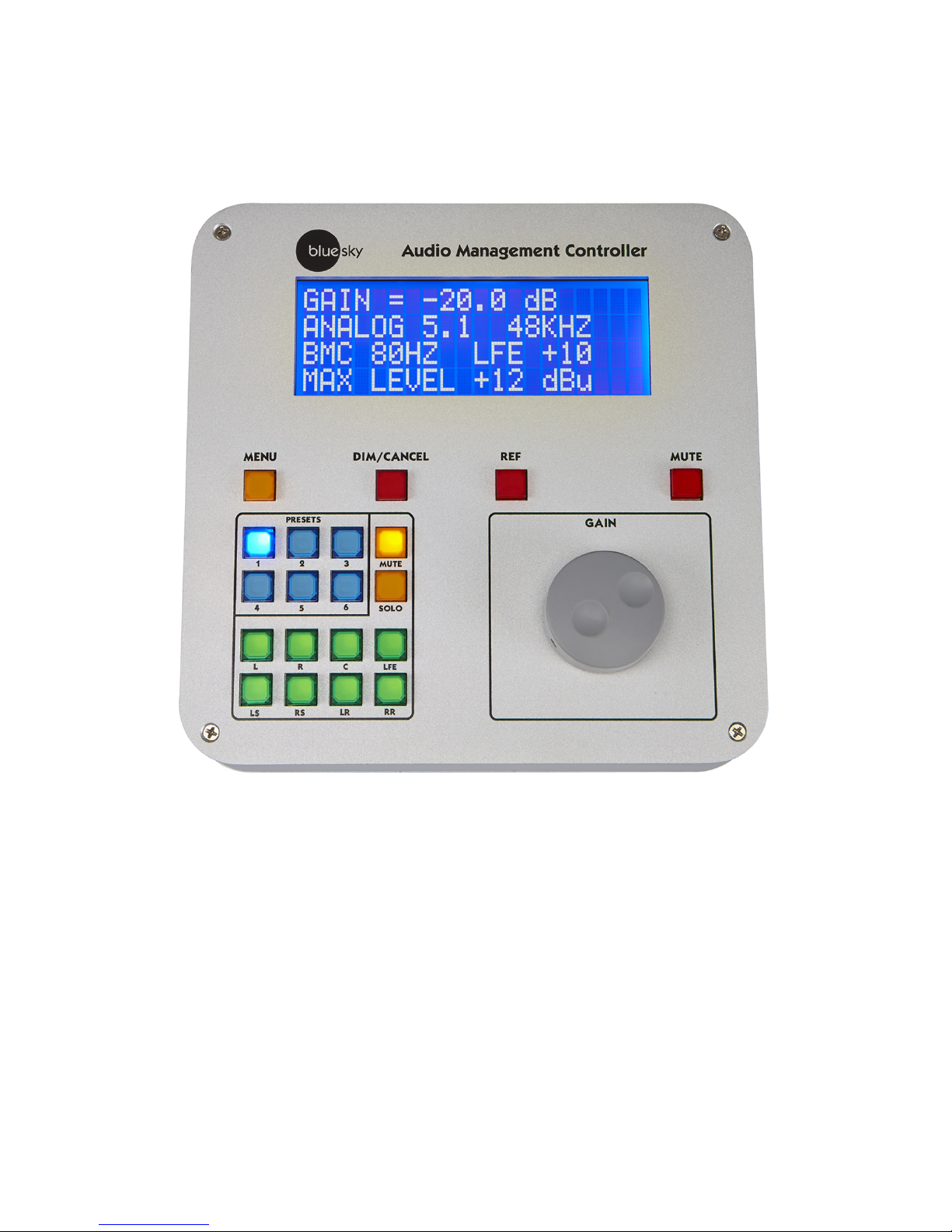
The AMC Remote
The AMC Remote / Operation
MUTE – mutes all channels, both digital and analog
REF – sets the system gain to a user defined reference level. The default setting is -20 dB. The
default setting can be changed using the remote menu or the AMC Control Software.
Page 10

Page 10
DIM/CANCEL – sets the system gain to a user defined level. The default setting is -30 dB. The
default setting can be changed using the menu or the AMC Control Software. The DIM/CANCEL
switch is also used to exit the menu mode
MUTE MODE – mutes the selected channels when the channel button is pressed.
SOLO MODE – solos the selected channels when the channel pressed.
SOLO/MUTE BUTTON – switches between modes
PRESETS – loads the preset.
MENU – switches the remote to menu mode, which allows a limited number of parameters to be
changed on a preset. When exiting the menu mode, the changed parameters are automatically
stored in flash memory.
GAIN – changes the system gain in increments of +/- 1 dB. Also used to scroll through the menu
and change parameters.
The Menu
You enter the menu by pressing the Menu switch and leave the menu by pressing the Dim/Cancel
switch. The menu works in 2 modes. A scroll mode to scroll the parameters using the gain control.
And a parameter mode to change parameters using the gain control. To switch between modes,
you tap the Menu switch. When you tap the Dim/Cancel switch to leave the menu mode, the
preset is automatically saved with the updated parameters.
An example of using the MENU to change the left calibration to +3 dB.
1) Tap the Menu switch.
2) Rotate the gain control to cycle through the menu items to Left Cal.
3) Tap the Menu switch to enter parameter mode.
4) Rotate the Gain control CW or CCW until the display reads +3.0 dB.
5) Tap the Menu key to go back to scroll mode.
6) Tap the DIM/CANCEL button to exit the menu and store the preset.
7) To change multiple items, follow 1-5 on each parameter and then hit the Dim /Cancel
button when you have completed all your changes.
Page 11

Page 11
Menu Items
1) Channel Calibration – sets the output channel gain and is used to balance channel levels
2) Channel Delay – sets the time delay for the selected channel. Channel delay is used to
time-align each speaker to compensate for the unequal distances between the listener and
the speaker. For example, a subwoofer is usually farther away from the listener than the
front speakers, so the sound from the subwoofer arrives later than the sound from the front
speakers. In this case you would add additional time delays to each of the front speakers to
time align with the subwoofer. The time delays of each speaker can be measured using the
AMC Control software and the optional recommended measurement microphone and USB
audio interface. (See the section on additional equipment you will need, below.)
3) Lip Sync delay – Many video displays have video processing delays, which can cause the
audio to be out of sync with the picture. To compensate for video delay, an overall audio
time delay can be added to re-synchronize the audio with the picture.
4) Reference gain- sets the system gain when the reference button is pressed.
5) Dim gain- sets the system gain when the dim button is pressed.
6) +12/+24 Analog Max IO Level – Some studio monitors are high gain devices that have a
nominal input level of around -10 dBu, and not +4 dBu. This switches gain structure to +12
dB to optimize the signal to noise ratio. This only affects the analog inputs and outputs.
7) Pink noise – outputs a low level pink noise signal on the analog and digital outputs on the
selected channel. The Gain control cycles through each channel assignments to speakers
6) Restore factory default - clears all entered preset data and restores the factory presets.
Follow the prompts on the display.
8) System sample rate – selects an internal system sample rate of either 48 or 96 kHz.
Changing the sample rate can only be done through the AMC remote and will reset the
system. It is recommended that the user exit the AMC control program before doing this.
9) Analog/Device input selection – selects either digital or analog on each of the paired
inputs. If a digital source is selected, the display will indicate if the channel is locked to a
digital source.
10) Bass Management ON/OFF- this parameter is a quick override on bass management If
bass management is turned off, all crossovers except for the LFE filter are disabled and the
individual input channels feeds to the LFE output are turned off.
Page 12

Page 12
Firmware Updates
The firmware in both the remote and rack can be updated through the USB ports and using the
Blue Sky Firmware Tool. There are separate updater tools for the Remote and Rack.
Currently the firmware update tool only works under Windows or an Apple computer running
Windows using Boot Camp or a virtual machine using Parallels or VM Ware. Because Boot Camp
runs Windows natively, it is the preferred method of running the AMC software on an Apple
computer.
A native OSX version is in process.
NOTE: Different versions of the AMC control software require firmware version numbers matching
the AMC control software version number. For example, AMC control firmware 4.12 requires
firmware version 4.12 be installed in the remote and rack. Future versions, i.e., 4.12B, will all work
with AMC Control software of the same number.
Upgrading the firmware in the AMC RACK to the latest version.
Note: The firmware can only be updated when the rack is powered down.
1. Install the Blue Sky AMC RACK Firmware X.XX update tool. The
Installation tool will create a Blue Sky folder in the Program Files (0x86) sub-directory and
Install the update program and the new hex file in that directory. The firmware update
tool uses the Microsoft Net Framework run-time library, which is normally already
Installed with Windows. If it won't run, install "vcredist_x86.EXE" and
"dotNetFx35setup.exe".
2. If you get a message that the program requires Elevation and will not run, right click on the
installer and click Run As Administrator.
3. Power down the AMC RACK and plug-in the USB cable. If this is first time you've
connected the AMC Rack to your computer, you may get a message that the computer
Is installing drivers for the USB interface. Wait until that completes and tells you it's
been successful. The front panel LED should flash a couple of times a second.
4. Start the program and the dialog box will show
BLUE SKY
AMC RACK BOOTLOADER REV 1.00
and the currently installed firmware.
5. If the dialog windows says
BLUE SKY
AMC RACK REV x.xx
Page 13

Page 13
Application unable to communicate with the device
Power off the unit, disconnect the USB cable, and plug the cable back in and restart
the program.
6. Click the UPDATE FIRMWARE BUTTON
7. The updater will update the firmware and read the new firmware version.
8. Close the program, disconnect the USB cable and you are done
Upgrading the firmware in the AMC Remote to the latest version.
Note: The firmware can only be updated when the remote is disconnected from the rack.
1. Install the Blue Sky AMC Remote Firmware X.XX update tool. The
installation tool will create a Blue Sky folder in the Program Files (0x86) sub-directory and
install the update program and the new hex file in that directory. The firmware update
tool uses the Microsoft Net Framework run-time library which is normally already
installed with Windows. If it won't run, install "vcredist_x86.EXE" and
"dotNetFx35setup.exe".
2. If you get a message that the program requires Elevation and will not run, right click on
the installer, and click Run As Administrator.
3. Disconnect AMC Remote and plug-in the USB cable. If this is first time you've
connected the AMC Remote to your computer you may get a message that the computer
is installing drivers for the USB interface.
4. Start the program and the dialog box will show
BLUE SKY
AMC Remote BOOTLOADER REV 1.00
and the currently installed firmware.
5. If the dialog windows says
BLUE SKY
AMC Remote REV x.xx
Application unable to communicate with the device
Power off the unit, disconnect the USB cable, and plug the cable back in and restart
the program.
6. Click the UPDATE FIRMWARE BUTTON
7. The updater will update the firmware and read the new firmware version.
8. Close the program, disconnect the USB cable and you are done
Page 14

Page 14
The AMC Control Software
The AMC Control Software is a 32 bit Windows 7 program that will only work when a Blue Sky
AMC is connected to the computer by USB. It is also compatible with Windows 7 64. It has not
been tested for other version of Windows. In addition, the program has been used successfully on
Intel based Apple OSX computers running Windows 7 via Boot Camp or in a virtual machine using
VMware or Parallels.
Installing the AMC Control software
Download the setup program and save it to your computer at a location where you can find it.
Double-click of the setup program to install it. The installer will create a folder under the program
files (0x86) called Blue Sky and install the program there.
Running the Program
Turn on the AMC and wait unit the red LED on the front of the AMC is flashing approximately once
every two seconds and the remote Mute button is lit. .
Plug the USB cable into the front of the AMC. If this is the 1st time you have connected the AMC to
your computer, you may see a message that says USB detected, installing software. Wait until this
process is complete and the LED on the front of the AMC goes back to flashing.
Start the AMC Control program and after a few seconds, you should see the following screen
Page 15

Page 15
AMC Main Control Panel
This is the main setup screen for the AMC control program. It shows which preset is loaded in the
AMC, and the current configuration of that preset. The AMC control program and the AMC rack are
interlinked through the USB connection so that actions on the remote, such as changing the
system gain, will be reflected in the AMC program and vice versa.
Navigating around the interface
Blue Boxes - represent items that are activated when clicked with your mouse. In some cases
clicking a blue box will initiate an action and in other cases it will open up another screen.
Black boxes with text represent parameters that can be entered directly using the delete key, the
backspace key, numerical keypad and the enter key. To change the value, select value you want
to change with the mouse, use the delete key to a erase the old value, type in the new value, and
hit enter. The value you enter using the keyboard is automatically checked to make sure it's in
acceptable range.
Check boxes represent an either/or setting. For example, if you click the left/right digital check box
it will automatically turn off the left right analog check box.
Page 16

Page 16
Gray Boxes are quick setup buttons, which configure loaded preset to those settings.
Light Blue Boxes - load Presets
White boxes – save presets
Master gain - system gain of the AMC
Reference gain - system gain when Ref Gain Switch is pressed
Dim gain - system gain when Dim Gain Switch is pressed
System sample rate - AMC internal sample rate. The system sample rate cannot be modified
through the AMC control program and can only be modified using the remote.
Loading a preset – click on any of the blue buttons in the upper left hand corner of the screen. If
the current loaded preset is modified the color of the button will change from blue to orange
Presets can also be loaded by pressing a button on the remote. When selecting presets from the
remote, the currently loaded preset is automatically saved to memory.
Saving a preset - click on any of the saved presets buttons to save the currently loaded preset to
the original location or a new location.
+12 dB Max/+24 dB Max Analog Max IO - sets the analog I/O to a maximum of +12 or +24 dBu.
When using strictly analog I/O, the nominal gain at reference 0 is 0 dB. However, if you're using
digital in and analog out, changing the analog output level from +12 to +24 will cause a +12 dBu
drop in level on the analog output.
Channel analog/digital input switches- selects the input source as either digital or analog. Digital
inputs have 140 DB dynamic range sample rate converter that will convert any digital input sample
rate from 44.1 kHz to 192 kHz signal to the AMC internal sample rate.
Digital in lock status box – indicates whether a digital input has achieved lock
8 in 8 out mixer box - opens the cross mixer panel
Bass management box– opens the bass management panel
EQ boxes - opens the EQ panels
Preset display – these 4 lines of text is what appears on the remote when a preset is loaded.
Each line of text can be changed directly using the keyboard, delete and backspace keys.
Channel Calibration – sets the relative balance between the channels. These values can be
entered directly in the boxes or entered automatically using the SRO procedure. See the Speaker
Room Optimization (SRO) section below for more information. Values entered in the calibration
boxes, will show in the menu on the remote and vice versa
Page 17

Page 17
Channel delay in milliseconds – sets an individual channel delay. Used for time alignment of
speakers in 5.1 and 7.1 setups. The channel delays can be entered manually or through the SRO
process.
Lip sync delay - add additional audio delay to compensate for the processing delay of video
monitors and displays
Analog gain - sets an offset for all analog output channels. Used primarily to correct for
imbalances between digital in and analog out or to scale the analog outputs of the entire box gain.
Digital gain – sets the offsets for all digital outputs primarily to correct gain differences between
analog in and digital out.
Go to SRO- opens up the SRO screen.
Save presets to file - saves all 6 presets to a text file. Used to archive presets or to provide a
backup if an AMC has to be restored
Load Presets from file - loads a complete set of 6 from a text file.
Page 18

Page 18
Cross Mixer
The cross mixer screen shows the routing of each input to each output in gain in dB. The gain can
be entered directly in the box or to mute an input type in “off” or”OFF” in the box.
If bass management is turned OFF (see Bass Management), the non -LFE feeds to the LFE
output channel will be disabled and displayed in red indicating that they cannot be changed. If in
this state, the user will have to go to the base management screen and turn bass management ON
before these values can be edited.
The gray buttons along the bottom of the screen configure the mixer to a variety of common
setups. These buttons only program the cross mixer and do not affect the bass management
settings.
To go back to the main AMC control screen click the X in the upper right-hand corner of the screen
Page 19

Page 19
Bass Management
The bass management screen shows the bass management settings for each individual channel
and the graphs show the resulting frequency response of the crossover filters only, without
equalization
For each channel the type of filter employed and the cutoff frequency of that filter can be selected.
The filter labels have the following meanings:
Bypass
No filter in circuit
LP2
2nd order 12 dB/oct low pass filter with a Q of .707
LPBW4
Two LP2 filters in series resulting in a 24 dB/oct low pass
LP6
6th order Chebyshev 36 dB/oct filter (typical LFE Filter)
HP2
2nd order 12 dB/oct high pass filter with a Q of .707
HPBW4
Two HP2 filters in series resulting in a 24 dB/oct high pass
For the feeds to the subwoofer, you have a choice of Bypass, LP2, LPBW4 and LP6 filters.
In addition to the low pass filters for the subwoofer, there are auxiliary high pass filters that can be
activated on each channel feed to the subwoofer. The choices for the high pass filter are Bypass,
HP2 and HPBW4. Normally these filters are engaged when using bass management where you
want to limit the low frequency response sub for that channel.
For example, if you're doing editorial work on a soundtrack that is being mixed for a theatrical
Page 20

Page 20
release, the front speakers typically only go down to 40 Hz. When mixing audio on a bass
managed system to a 20 Hz subwoofer, the resulting mix when played back on a theater system
can lack bass. So to get better a translation, you could employ a 40 Hz HP2 or HPBW4 high pass
filter on the left, center, and right channels.
The same holds true for surround speakers. In a typical theater setup, the surrounds do not go
down below 60 Hz. To get better translatability you can employ a 60 Hz high pass filter on the
surround channels.
The AMC system also includes a high pass filter for the each channel.
These filters are not in the subwoofer feeds but on the individual channels. The choices are
Bypass, HP2 or HPBW4.
The bypass setting is used when you're not using bass management.
HP2 or HPBW4 are used depending on the actual speaker attached to the channel. If the speaker
is made for bass management, (i.e., Blue Sky SAT6D) then you would use HP2 set to 80 Hz. If
however, if the attached speaker is a full range monitor that may go down to 50 or 40 Hz, you'd
use a HPBW4 to get a better blend with the subwoofer.
Bass Management on/off - turns bass management on and off. When bass management is OFF,
all crossovers are disabled except for the LFE filter. When in this mode, none of the filters on the
screen can be modified which is indicated in red. To modify any of the filter settings make sure
bass management is turned ON.
Grey Preset buttons The gray buttons along the bottom of the bass management screen are
presets for common bass management setups. Note: these presets only affect values on the base
management screen and do not program the cross mixer.
Page 21

Page 21
EQ Screen
Each channel of the AMC has a 31 band 1/3 octave graphic equalizer and 8 uncommitted filters.
Graphic EQ - the AMC has a 31-band 1/3rd octave EQ. Clicking on the slider, holding the left
mouse button, and moving the slider up and down can change the graphic EQ values. The upper
graph will show any changes to the filters.
Max Filter Cut and Boost dB - set the upper and lower boost limit during optimization. Used to
set the maximum amount of correction, the optimizer will use for any filter.
Optimize - The optimize check box determines whether the graphic EQ or any of the individual
filters will be used in the speaker room optimization process. The active check box determines
whether the filter is used or bypassed.
Active - sets whether the filter is in use or bypassed.
Filter type - select the filter type by clicking the downward caret, which will open up a selection
box
Frequency - sets the cutoff frequency
Q- sets Q of the filter
Boost - sets the boost / or cut in dB for the low shelf, high shelf, and parametric filters
Page 22

Page 22
Save EQ to Presets - saves the displayed EQ setting to any preset. This feature is commonly
used to copy EQ data from one preset to another preset.
Display EQ channels - switches the screen to a different EQ without having to close and re-open
the screen
Page 23

Page 23
Speaker Room Optimization (SRO)
Overview
SRO is a system for measuring the acoustic response of a speaker system and correcting the
speaker system to a target frequency response.
The measurement portion of SRO uses a special noise signal called a maximum length sequence
(MLS). Unlike white or pink noise, MLS signals have unique properties that allow them to be used
to calculate the impulse response, which contains the complete frequency, phase, and time
response of the speaker.
Processing the impulse response with the use of a Fast Fourier Transform (FFT), the frequency
response of the speaker can be calculated and displayed.
Once the speaker frequency response is obtained it can be compared against the desired
frequency response and then the frequency response of the AMC be modified to correct the
speaker response to closer match the target.
The target curve can be an “X” curve, a flat frequency response curve, or an arbitrary curve that
the user created.
To find the combination of filters that best corrects the desired frequency response target, the AMC
control software uses a proprietary genetic mutation algorithm called BOO.
BOO mathematically generates thousands of different EQ settings and determines which one
gives the best match to the target curve. Once BOO picks the best match, the user has the option
of accepting it, or tweaking manually from there.
NOTE: The SRO program will correct many frequency response problems, but it does have
limitations. It will not give repeatable and reliable results if the room is too noisy or if the room has
too high a reverberation time.
Additional equipment you will need
The Blue Sky SRO program uses an inexpensive USB audio interface and measurement
microphone to generate test tones and measure the frequency response of the speakers attached
to the AMC.
You will need the following:
1) Measurement microphone - the recommended choices are the Dayton Audio EMM-6 or
Page 24

Page 24
Behringer ECM8000. However, it is possible to use other high quality measurement
microphones, but the above are known to work fine, and are relatively inexpensive.
2) USB Audio Interface - the ART USB Dual PRE is the recommended USB audio interface
used for measurement. It is an inexpensive system with dual microphone preamps, dual
audio outputs, operates at 48 kHz and has a phantom power supply for the measurement
microphones. It uses the built-in driver for windows.
3) Microphone stand.
4) 2 - 1/4" TRS- to XLR male microphone cables. One can be short (1.5 ft) for the loop back
connection and one should be long enough to connect to the speaker.
5) XLR microphone cable for the measurement microphone
Measuring and optimizing your speaker system
Optimizing your system requires the following steps
1. Set up your microphone. (page 20)
2. Connect the USB-Dual Pre to the microphone, and to analog input 8 on the AMC rack
3. Set the USB audio interface is the default recording and playback device and it is set up
with the correct properties. (See page 21).
4. Connect a USB cable to the front of the AMC and computer and when ready start the AMC
control program. Go to the SRO Screen (page 23)
5. Setup your Target curves for each individual speaker with any customization that you may
need. (Page 24)
6. Load the preset you want to use to store the optimize values.
7. Set the gain on the AMC Remote for 0 dB.
8. If the AMC has a previous optimized EQ loaded that you want to remove hit the Clear EQ
9. Select one or more speakers on the SRO panel, and hit the Measure button. It is
recommended that you optimize the subwoofer after optimizing the other speakers.
10. Adjust the output on the back of the Dual Pre if necessary to get a consistent measurement
11. Once you have consistent measurements, you can click the Optimize button to optimize
the system. During the optimization process, the channel began optimized will automatically
pop up in a new window to show you the process. Once it was once it is done with that
speaker, the window will automatically close and the next speaker in the queue will pop in
Page 25

Page 25
the view.
12. Once the process is complete you can click on any of the small EQ graphs to expand them
and to check the filters or to manually tweak him to your own liking. Page 18
13. Once you are satisfied with the results, you can close out the SRO screen, and save the
preset. Also thru the EQ screen you can save the EQ setting to other presets.
Guidelines on microphone setup
Typical small diaphragm measurement microphones have an Omni-directional response pattern
over most of the audio band with a slight narrowing of the pattern as frequency of approach 20 kHz
Most speakers on the other hand, have an Omni-directional pattern only at frequencies below
1kHz. Based on these characteristics, here are some general guidelines on setting up
measurement microphones
1. The height of the microphone should be placed at ear level.
2. Most of the frequency response problems in rooms are related to standing waves
and boundary effects which occur at frequencies below 1KHz, and typically below
200 Hz. If this is the main area the user wants to focus on, the exact aiming of the
microphone to the speakers is noncritical. The mic can be pointed at the speaker, or
an angle of 45°, or straight up.
3. If you're interested in correcting frequencies over the full audio bandwidth, and the
mixing position is within 1m to 2 meters, you should point the microphone towards
the speaker for best results.
4. In larger rooms, where the speakers are many meters away from the mixing position,
the direction the microphone is pointing is less critical, and the recommended
microphone position is pointing up approximately 45°.
In all cases, if you are unsure of your microphone placement you should do a couple trial
measurements with different microphone positions to see which gives you the best response.
Page 26

Page 26
Setting up the ART USB Dual Pre to use with Blue Sky SRO Software.
1) Plug the short TRS to XLR male cable from the Dual Pre right output to the Dual Pre right
microphone input.
2) Set the mix fader to computer (Max CW).
3) Set the output level straight up (12 O'clock).
4) Press the phantom switch to on.
5) Press the power to on.
6) Plug the measurement microphone into the Dual Pre left microphone input.
7) Set the left gain to 16.
8) Set the right gain to 1.
9) Plug the USB cable from the computer into the ART USB interface on the back. If it's the 1st
time the device is connected to the USB port you'll get a driver installation message.
10) Setup the ART as the default playback device and set its Playback properties.
Windows Control Panel-> Sound-> Playback ->USB Audio CODEC -> Set Default
Properties- >Advanced-> 16 bit, 48000Hz (DVD Quantity) -> OK.
11) Setup the ART Dual Pre as default recording device and set its recording properties.
Windows Control Panel-> Sound->Recording->Microphone USB Audio CODEC ->Set
Default
Properties-> Listen-> Uncheck ->Listen to device
Properties-> Levels-> 100.
Properties-> Advanced-> 2 channel 16bit, 48000 Hz ->OK.
NOTE: If you disconnect the ART Dual Pre from your computer, during the above setup, you may
have to go through this process again.
Page 27

Page 27
Setting up the ART USB Dual Pre for use with the AMC SRO
1) Using a microphone stand set the measurement microphone at your listening position and
at ear height.
2) Connect the microphone to LEFT in on the ART USB Dual Pro. Set the gain control on the
LEFT input to 18.
3) Connect the RIGHT output of the ART to the RIGHT Microphone In. Set the gain control to
3.
4) Connect the output of the ART Dual Pre Left channel to Right Rear analog input on the
AMC.
5) On the rear of the ART set the MIX knob FCW to Computer.
6) On the rear of the ART set the LEVEL knob to 12 o’clock (straight up)
7) On the rear of the ART press the PHANTOM IN.
Page 28

Page 28
The SRO Main Screen
This screen shows the current state of the EQ, target filters, measured frequency response and
corrected frequency response of all the channels. Clicking on the any of the small graphs will open
up a larger graph.
NOTE: You can't optimize a channel until you measure the channel.
The SRO screen has the following features and operations:
Frequency response - displays the measured and corrected frequency response of the selected
speaker.
Target - displays the desired frequency response after correction.
EQ - the electrical EQ with the speaker.
Select - determines whether the speaker will be measured and/or optimized.
Measure - measures the frequency response of the selected speakers.
Optimize - starts the SRO optimization process. This box will be de-activated until a measurement
has been made.
Page 29

Page 29
Clear EQ - clears the values of all filters in the AMC.
The optimum level average microphone level is somewhere is between -20 dB to 0 dB.
If the level is low, increase the gain on the remote control. If the measured response is too low, the
noise floor of the room and or the microphone may prevent an accurate measurement.
Normally when optimizing a Blue Sky system, the remote gain control is set for 0dB.
Page 30

Page 30
Target Curves
The SRO optimizes a speaker to a target curve, which sets the desired frequency response.
Target curves can be created using the presets buttons (along the bottom of the screen) or
manually created by activating and configuring the various filters.
To review or adjust the Target curve for any speaker, click on the target curve, which will bring up
the following screen.
In all AMC control software above rev 4.11, all target curves are saved to a file when any target
curve is modified. Therefore, when you re-start the AMC control program in a new session, the
program will remember your target curves without having to re-create them from scratch.
The target screen contains the following items:
Target Filters – the target filters are used to create the target curve. In many situations the target
filters are automatically selected from the values entered in the bass management panels. In
addition there are preset buttons along the bottom of the target curve panel.
If the target curves are not appropriate for your application, you can construct a custom target
curve using any or all filters. Any changes to the filters are automatically reflected in the graph at
the top of the screen
Page 31

Page 31
Note: Not all the values in the boxes are used for all filters. For example, the slope, dB/oct, and
Q, are not used for HPBW4, etc. If you change a value and there is no change in the graph, that
parameter is not used. Also, the High Pass Shelf and Low Pass Shelf filters are not “real” shelving
filters but special target filters. "Real" low pass and high pass shelving filters have roll-offs that are
multiples of 6 dB /oct. The special target filters can have an arbitrary roll off. For an example, in
post-production, near-field monitors used for editing may require a 3-dB/oct roll-off above 4 kHz so
the sound translates better to the dubbing stage. Although a 3 dB target curve can be constructed
with conventional filters, it may take 6 or more separate filters and a lot of experimentation to get
the target curve you want. However, with the special target shelf filters, you can enter -3 dB directly
without all the fuss and it is much easier.
Target Scale Low and High Freq – the software uses the frequencies between these values to
calculate the avg. microphone level, which is used to adjust the target curve, so it “floats” with the
drive level. These frequencies are selected to be in a “flattest” portion of the measured curve.
The default range for satellite speakers is 500 Hz to 2.5 kHz. while for subwoofers the default
range is 40Hz to 80 Hz. However these values can be modified to suit your particular
circumstances.
Low and High Target Freq – these two frequencies restrict the range of the optimizer. Any
frequencies outside this range are excluded from the optimization process, allowing you to limit the
range of optimization. Any filter, either graphic EQ, or a user assigned filter, outside of this range
would not be altered by the optimization process. For example, suppose you wanted to only
correct the low frequency portion of the main speakers from say 40 to 200 Hz. In that case, you
would input 40 Hz in the low target frequency and in 200 Hz in the high target frequency. When the
speaker is optimized, any one 3rd octave filters outside this range would not be modified, nor with
any user assigned filter outside this range be modified.
Gate time in milliseconds - this value sets how much of the impulse response is used to calculate
the frequency response. The AMC SRO program uses a Blackman – Harris window function on
the impulse response when calculating frequency response. The gate time determines how much
of the low frequency content of the impulse response to include in calculating frequency response.
The lower the frequency you want to measure, the longer the gate time needs to be so it includes
more of the low frequency energy that's contained in the impulse response.
Page 32

Page 32
AMC Specifications
Analog Noise Floor -106 dBu / -96dBu (20 Hz - 20 kHz flat) +12/+24
Analog Dynamic Range 118 dB
Maximum Analog Input +12 dBu / +24 dBu
Maximum Analog Output +12 / +24 dBu
Analog THD + N .002% +4 dBu In (20 Hz -20 kHz)
Digital THD + N .00002% -20 dBFS (20 Hz - 20 kHz)
Digital In Lock Range 44.1 kHz -192 kHz
Frequency Response 10 Hz – 22 kHz +0,-1dB
Lip Sync Delay 0- 176 ms @ 48 kHz
Channel Delay 0 -27 ms @ 48 kHz
Internal Processing Sample Rate 48 kHz / 96 kHz
Input power 90 to 240 V AC 50/60 Hz 42 watts
Chassis 19” rack 1 U high
Note: All specifications are typical and subject to change without notice.
 Loading...