

Page 1
SB3024iL DUO-Option Manual Addendum
For Models; SB3024i, SB3024Di, SB3024iL, SB3024DiL
Purpose
This manual addendum applies to the Solar Boost 3024i family of charge controllers which have received the DUO-Option upgrade
part number Upgrade/3024DUO
The DUO-Option
The 3024 includes a 20 amp auxiliary output. The basic DUO-Option is a software only upgrade which converts the auxiliary output
into a separate 20 amp Diversion type charge controller. The DUO-Option upgrade allows a 3024 to provide Diversion type charge
control for hydroelectric, wind or similar unregulated DC generator type power sources while at the same time providing MPPT type PV
charge control.
What is Diversion type charge control?
The core purpose of any charge controller is to prevent battery voltage from exceeding a certain charge voltage setting during
charging by reducing charge current delivered to the battery. A battery will charge if PV modules or a wind generator was connected
directly to a battery without a charge controller, but as battery state of charge rises so does battery voltage. Without a charge controller
voltage can rise so high once the battery is charged that the battery or attached systems may be damaged.
The Series Pass type charge control in the 3024’s MPPT system reduces current delivered to the battery when necessary to control
battery voltage by reducing the current it draws in from the PV and “passes through” to the battery. By contrast Diversion type charge
control has the power source connected directly to the battery. When charge current needs to be reduced to control battery voltage the
Diversion controller “diverts or redirects” a portion of the power source charge current away from the battery as the means it uses to
limit net battery charge current and control battery voltage. The diverted current is typically dissipated as heat in a resistive dump load.
Diversion charge control operation
When multiple 3024’s are networked together without the Diversion control upgrade they essentially operate as separate PV power
controllers under the direction of a single charge control system. Charge voltage setpoints and all charge control “smarts” reside within
the charge control system. If one or more PV power controllers receives PV input power the charge control system starts and directs the
activities of the one or more PV power controllers to deliver the 3024’s sophisticated multi-stage battery charge control.
The Diversion control upgrade creates a completely separate 100Hz Pulse Width Modulation (PWM) Diversion type power controller
within the 3024 using the 3024’s existing 20 amp auxiliary output. The Diversion power controller has it’s own turn on criteria which is
when battery voltage reaches the present charge voltage setpoint (typically 14.4/28.8V). When this battery voltage threshold is reached
Diversion turns on (whether PV power is present or not) and the Diversion power controller as directed by the charge control system
begins to divert current to a resistive dump load as necessary to reduce net charge current and control battery voltage. The charge
control system then progresses through it’s normal multi-stage charge process to precisely control battery charge.
Min-Power / Max-Power modes
A key aspect of the Diversion control upgrade is it’s coordinated interaction with PV charge control. This interaction allows the user to
select whether minimum or maximum possible power is delivered to the dump load. Note that this coordinated interaction occurs within
a 3024 only and not among multiple 3024’s on the IPN network. Min-Power / Max-Power mode is selected with 3024 Dip #4.
Diversion
Operating
Mode
DIP
Switch
#4
OFF
Min-Power
Mode
(formerly
Aux Bat
Chg)
ON
Max-Power
Mode
(formerly
Load
Control)
. This addendum should be used in conjunction with the standard product manuals.
Diversion Control Operation
When battery voltage climbs to the present charge voltage setpoint in the Min-Power mode the PV power
controller reduces current delivered to the battery to control battery voltage in the same manner as a
standard 3024. The Diversion power controller remains off until the PV power controller is unable to
reduce current enough to control battery voltage. Once PV output is at a minimum, the Diversion power
controller begins to divert current to the dump load to further reduce net charge current and control
battery voltage. Min-Power mode is typically selected when dump load power is not directed towards a
useful purpose and minimum dump load heating is desired. If no generator is present in Min-Power
mode a dump load is unnecessary as the PV power controller alone controls all charge current.
When battery voltage climbs to the present charge voltage setpoint in the Max-Power mode the PV
power controller continues deliver maximum PV power. While maximum PV power production continues,
the Diversion power controller diverts current to the dump load to reduce net charge current and control
battery voltage. If the Diversion power controller is unable to divert enough current to control battery
voltage, the PV power controller will reduce current to assist in controlling battery voltage while the
system as a whole delivers as much power as possible to the dump load. Max-Power mode is typically
selected when dump load power is directed towards a useful purposes such as heating water. The MaxPower mode may be used with PV power alone if the user wishes to divert PV power not required for
battery charging to a useful purpose. Note that a dump load must be present in Max-Power mode to
ensure stable battery voltage control.
Page 1 of 4
Page 2
Microprocessor installation (required for field upgrade only)
¾ WARNING:
standard electrostatic handling precautions. At a minimum discharge yourself by touching grounded
metal prior to handling the microprocessor or touching circuits in the 3024. Touch the “BAT-” terminal in
The microprocessor or 3024 may be damaged by static electricity. Observe industry
the 3024 just prior to removing the old microprocessor or inserting the new microprocessor. The risk of
electrostatic damage increases greatly if relative humidity is below 40%.
The Microprocessor must be inserted in the proper Pin-1 orientation and all pins must be properly
seated into the socket.
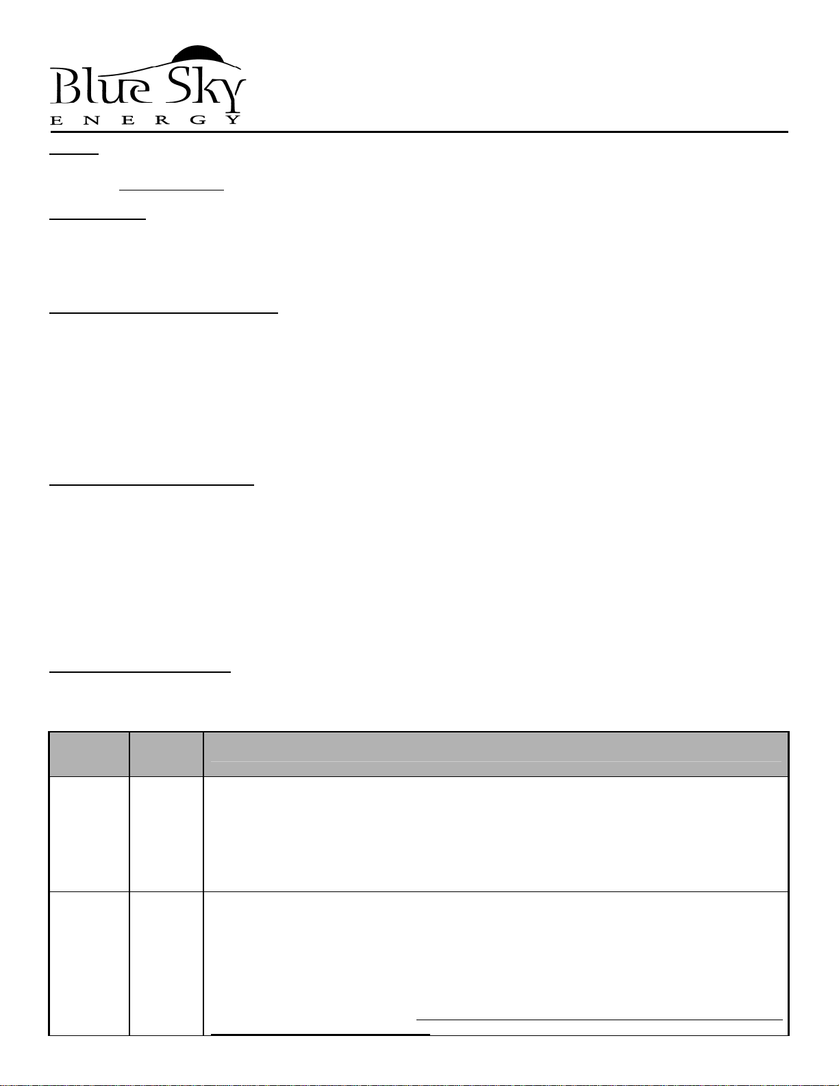
1. Remove all sources of power, battery and PV.
2. Carefully remove the old microprocessor with a suitable tool. Take care
not to damage the microprocessor socket or other components.
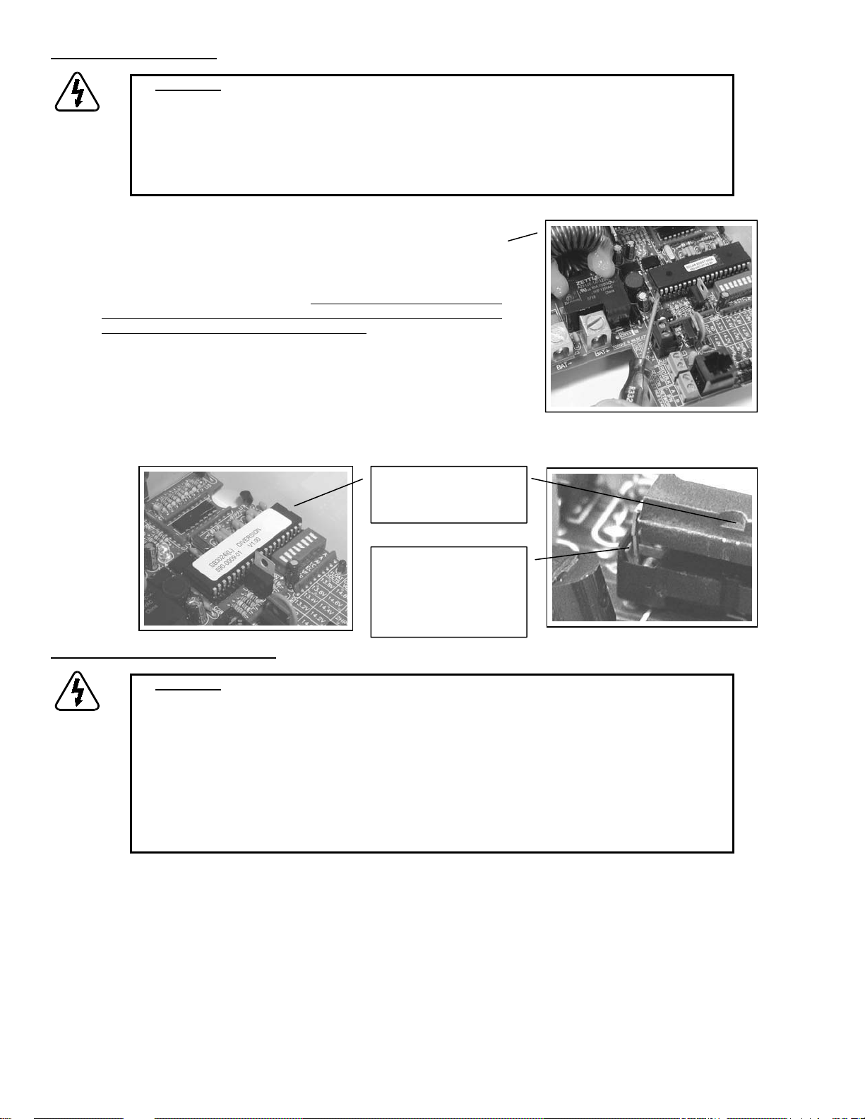
3. Carefully place the new microprocessor p/n 590-0009-01 onto the
socket, but do not press into place. Confirm that the Pin-1 end of the
microprocessor is in the proper orientation closest to the case wall and
that all pins are properly placed into the socket.
4. With one finger on each end of the microprocessor, carefully and
evenly press the microprocessor to fully seat it into the socket. Confirm
all pins are properly seated into the socket with no bent pins, and again
confirm Pin-1 orientation.
5. Reapply battery power. Confirm that the microprocessor operates by
viewing the charge voltage setting value (V
) as described in the
CHG
3024 manual.
Place Microprocessor
into socket with Pin 1
orientation where shown.
Confirm that each pin is
properly placed into
socket prior to pressing
microprocessor into
place.
Dump Load selection and installation
¾ WARNING:
reduce the risk of fire, connect the auxiliary output to 25 ampere maximum over current protection in
accordance with National Electrical Code, ANSI/NFPA 70. Do not connect the auxiliary output to a dump
Over current protection for the 3024’s auxiliary output must be provided externally. To
load capable of drawing more than 20 amperes at the highest battery charge voltage. For dump load
current up to 40 amperes use current booster module part number CBM4070. Over current protection for
CBM4070 must be provided externally. To reduce the risk of fire, connect CBM4070 to 50 ampere
maximum over current protection in accordance with National Electrical Code, ANSI/NFPA 70. Do not
connect CBM4070 to a dump load capable of drawing more t han 40 amperes the highest battery charge
voltage. Install and wire the dump load in accordance with the dump load manufacturer’s installation and
safety instructions and National Electrical Code, ANSI/NFPA 70. For dump load wiring clarity these
instructions omit standard 3024 installation. These instructions show generalized connections only and are
not intended to show all wiring, circuit protection and safety requirements.
For proper battery voltage control the dump load resistor value should be just low enough consume full generator current, but not so
low as to exceed the maximum current ratings of the 3024’s auxiliary output or the CBM4070. Since any charging source that drives
battery voltage up to or above the 3024’s charge voltage setpoint will cause current to be delivered to the dump toad, care must be
taken in the selection of both the 3024’s charge voltage setpoints and the charge voltage setpoints of other charging sources. To
prevent the Diversion control system from diverting current to the dump load from other charging sources such as an AC powered
charger or engine driven alternator, the 3024’s charge voltage setpoint must ALWAYS be greater than the voltage applied by these
other chargers. This may necessitate eliminating the 3024’s lower voltage Float charge stage by setting the 3024 for 2-stage charge.
Minimum dump load resistor value may calculated as follows:
R
DUMP-MIN
V
I
= V
BAT-MAX
÷ I
DUMP-MAX
Where: R
DUMP-MIN
BAT-MAX
DUMP-MAX
= Minimum value of dump load resistor in Ohms (Ω)
= Maximum expected battery charge voltage in Volts (V)
= Maximum dump load current in Amperes (A)
Page 2 of 4
Page 3

Minimum Dump Load Resistor
Nominal Battery Voltage
12V
V
V
Dump Load and optional Current Booster Module wiring
The 3024 can directly drive dump loads up to 20 amps. For dump loads of up to 40 amps the optional the Current Booster Module
(CBM) part number CBM4070 may be used. The CBM consists of a large optically isolated MOSFET output stage which turns on when
a 3 to 32VDC drive signal is present on it’s input. The 3024’s 2A-CHG output is used as the PWM drive signal for the CBM. For dump
load needs in excess of 40 amps multiple CBM’s may be driven from a single 3024. For these applications multiple CBM inputs are
connected in parallel. CBM outputs must connect to separate 40 amp maximum dump loads with separate 50 amp maximum over
current protection. Do not directly parallel outputs.
BAT-MAX
24V
BAT-MAX
= 15V
= 30V
3024’s Auxiliary Output
20 Amp Maximum
0.750 Ω 0.375 Ω
1.500 Ω 0.750 Ω
Minimum Dump Load Resistor
CBM4070
40 Amp Maximum
Connect to 20A LOAD terminal.
¾ Generator Connection: The
wind/hydroelectric generator connects directly to the battery and
is intentionally omitted in this
wiring diagram so as to not
preempt the generator manufacturers installation and safety
instructions.
25 amp max over
current protection
Dump Load
20 amp max
Dip #4 select becomes:
OFF = Min-Power Mode
ON = Max-Power Mode
3024 directly driving dump
load up to 20 amps
Connect CBM4070 to
2A CHG terminal. This
3024 output provides
internal 2 amp over
current protection
Dump Load
40 amp max
¾ WARNING: Current Booster
Module part number CBM4070
must be mounted with heatsink
fins oriented vertically as shown
to facilitate convection cooling.
Do not separate power module
from heatsink, enclose in a
confined space or restrict air
flow. Do not connect the input or
output reverse polarity or exceed
the 40 amp PWM current rating.
Current Booster Module
CBM4070
3024 driving dump load up to 40 amps with
optional Current Booster Module p/n CBM4070
Page 3 of 4
50 amp max over
current protection
Page 4

Clamp on ferrite suppressor noise
The 3024iL is shipped with two clamp on ferrite suppressors to minimize EMI radiation and susceptibility. One is placed around both
battery wires, and the second is placed around the battery temperature sensor and remote display wires. If the 20A Load output drives
the dump load directly it is possible that the battery wire suppressor may emit a 100Hz buzzing noise resulting from the 100Hz PWM
diversion current.
This noise can be eliminated by also routing the dump load wire from the 20A Load output through the battery wire suppressor in the
same direction as the battery wires. If wire size is such that all three wires cannot fit through the existing battery wire suppressor an
additional suppressor may be used. One suppressor should be placed around the BAT- wire alone. The other should be placed around
both the BAT+ wire and the dump load wire. Routing both the BAT+ wire and the dump load wire through the same suppressor in the
same direction cancels 100Hz magnetic field in the suppressor which eliminates the noise. Additional suppressors may be ordered as
BSE part number 523-0005-01.
Wind/Hydroelectric generator installation and wiring
The DUO-Option is normally suitable for use with DC generators requiring diversion type charge control. If the generator includes a
voltage regulator it’s setpoint must be set slightly higher than the 3024’s maximum charge voltage setpoint including the effects of
temperature compensation.
¾ WARNING:
The generator DC output must be connected to the battery in accordance with the
generator manufacturers installation and safety instructions. The generator is intentionally omitted in the
preceding drawing so as to not preempt the generator manufacturers installation and safety instructions.
DUO-Option diversion operation and associated dump load must meet the generator manufacturers
diversion charge control requirements. Do not connect the generator to the 3024’s PV inputs.
Diversion power controller indicators
As the Diversion power controller increases or decreases it’s PWM “on time” to adjust how much average current is diverted, the
3024’s auxiliary output LED indicator will vary in brightness in proportion to PWM percent on time. The LED will be brighter when more
current is diverted and will be completely off when no current is being diverted. If an IPN-ProRemote is present in the system it’s
auxiliary output screen in the Top Menu will always show Auxiliary Battery Charge. The auxiliary battery voltage displayed in this screen
will be the average voltage applied to the dump load and will vary with PWM percent on time. If actual battery voltage was 14.4V and
the Auxiliary Battery Charge screen shows 7.2V, then Diversion PWM duty cycle (% on time) = 7.2V ÷ 14.4V = 50%.
One year limited warranty
Blue Sky Energy, Inc. (hereinafter BSE), hereby warrants to the original consumer purchaser, that the product or any part thereof will
be free from defects due to defective workmanship or materials for a period of one (1) year subject to the conditions set fourth below. If
within the coverage of this limited warranty, BSE will repair or replace the product at BSE’s discretion. The original consumer purchaser
is responsible for all transportation costs and insurance related to returning the product to BSE. BSE will cover standard ground
transportation costs and insurance to return the product to the original consumer within the continental US.
1. This limited warranty is extended to the original consumer purchaser of the product, and is not extended to any other party.
2. The limited warranty period commences on the date the product is sold to original consumer purchaser.
3. This limited warranty does not apply to any product or part thereof damaged by; a) alteration or disassembly, b) repair or service
not rendered by a BSE authorized repair facility, c) accident or abuse, d) corrosion, e) lightning or other act of God, or f) operation
or installation contrary to instructions pertaining to the product.
4. BSE’s liability for any defective product or any part thereof shall be limited to the repair or replacement of the product, at BSE’s
discretion. BSE will not be liable for any loss or damage to person or property, or any other damages, whether incidental,
consequential or otherwise, caused by any defect in the product or any part thereof. Some states do not allow exclusions or
limitations of incidental or consequential damages, so the above limitation may not apply to you.
5. Any implied warranty for merchantability or fitness for a particular purpose is limited in duration to the length of this warranty. Some
states do not allow exclusions or limitations on how long an implied warranty lasts, so the above limitation may not apply to you.
6. This warranty gives you specific legal rights, and you may also have other rights which vary from state to state.
7. To obtain warranty repairs, contact BSE at 800-493-7877 or 760-597-1642 to obtain a Returned Goods Authorization (RGA)
number. Mark the outside of the package with the RGA number and return the product, postage prepaid and insured to the address
below. A copy of the purchase receipt identifying original consumer purchaser and date purchased must accompany the product to
obtain warranty repairs.
Blue Sky Energy, Inc.
2598 Fortune Way, Suite K
Vista, CA 92081 USA
800-493-7877 • 760-597-1642 • Fax 760-597-1731 • www.blueskyenergyinc.com
430-0027 B
Page 4 of 4
 Loading...