

Page 1
SOLAR BOOST™ 2000
20A 12V MAXIMUM POWER POINT TRACKING
PHOTOVOLTAIC CHARGE CONTROLLER
INSTALLATION AND OPERATION
MANUAL
THIS MANUAL INCLUDES IMPORTANT SAFETY INSTRUCTIONS
SAVE THESE INSTRUCTIONS
COVERED UNDER US PATENT 6,111,391
OTHER PATENTS PENDING
© RV Power Products 2000 430-0012 E
Page 2

RV Power Products - Solar Boost 2000
TABLE OF CONTENTS
IMPORTANT SAFETY INSTRUCTIONS.............................................................................. 2
PRODUCT DESCRIPTION................................................................................................... 3
OPERATION .................................................................................................................... 3
Maximum Power Point Tracking (MPPT)................................................................. 4
Typical Current Boost Performance............................................................ 5
How MPPT And Current Boost Works........................................................ 5
Optional Temperature Compensation...................................................................... 6
Optional Battery Manager 6210 Interface ................................................................ 6
Charge Operation With 6210 Controller ..................................................... 7
INSTALLATION 7
Over Voltage / Reverse Polarity Protection.............................................................. 7
Electrostatic Handling Precautions .......................................................................... 7
Installation Steps...................................................................................................... 7
Solar Boost 2000 Setup ........................................................................................... 7
Operating Mode .......................................................................................... 8
MPPT Disable ............................................................................................. 8
Maximum Power Voltage ............................................................................ 9
Optimizing MPPT ........................................................................................ 9
Temperature Compensation ....................................................................... 9
Charge Voltage ........................................................................................... 9
Solar Boost 2000 Installation ................................................................................... 9
System Wiring .......................................................................................................... 10
Battery Temperature Sensor.................................................................................... 12
Integrating With Battery Manager™ 6210................................................................ 12
SPECIFICATIONS ................................................................................................................ 13
THREE YEAR LIMITED WARRANTY .................................................................................. 13
TABLES AND FIGURES
Table 1 Typical Current Boost Performance ..................................................... 5
Table 2 Factory Default Setup........................................................................... 8
Table 3 Maximum One W ay Wire Length For Less Than 0.42V Drop.............. 12
Figure 1 Panel Layout......................................................................................... 4
Figure 2 Charge Voltage -vs.- Battery Temperature .......................................... 6
Figure 3 Setup Adjustments and Field Connections .......................................... 10
Figure 4 Preferred Wiring Method ...................................................................... 11
Figure 5 Battery Manager 6210 Interface ........................................................... 12
Figure 6 Mounting Template............................................................................... 14
RV Power Products
1058 Monterey Vista Way
Encinitas CA, 92024, USA
800-493-RVPP •••• 760-944-8882
www.rvpowerproducts.com
1
Page 3

Installation and Operation Manual
IMPORTANT SAFETY INSTRUCTIONS
1. Refer servicing to qualified service personnel. Incorrect installation may result in risk of electric shock or fire. No
user serviceable parts in this unit.
2. Remove all sources of power, photovoltaic and battery before servicing or installing.
3. WARNING - RISK OF EXPLOSIVE GASES
a) Working in the vicinity of lead-acid batteries is dangerous. Batteries produce explosive gasses during normal
battery operation.
b) To reduce risk of battery explosion, follow these instructions and those published by battery manufacturer and
manufacturer of any equipment you intend to use in vicinity of battery.
4. PERSONAL PRECAUTIONS
a) Someone should be within range of your voice or close enough to come to your aid when you work near a lead-
acid battery.
b) Have plenty of fresh water and soap nearby in case battery acid contacts skin, clothing or eyes.
c) Wear complete eye protection and clothing protection. Avoid touching eyes while working near battery.
d) If battery acid contacts skin or clothing, wash immediately with soap and water. If acid enters eye, immediately
flood eye with running cold water for at least 10 minutes and get medical attention immediately.
e) NEVER smoke or allow a spark or flame in vicinity of battery.
f) Be extra cautious to reduce risk of dropping metal tool onto battery. It might spark or short circuit battery or other
electrical part that may cause explosion.
g) Remove personal metal items such as rings, bracelets, necklaces, and watches when working with a lead-acid
battery. A lead-acid battery can produce a short circuit current high enough to weld a ring or the like to metal,
causing a severe burn.
h) Use charger for charging 12 volt lead-acid batteries only. Charging other battery types may cause these batteries
to burst and cause injury to persons and damage to property.
5. PREPARING TO CHARGE
a) Never charge a frozen battery.
b) Be sure battery is mounted in a well ventilated compartment.
c) Add distilled water in each cell until battery acid reaches level specified by battery manufacturer. This helps
purge excessive gas from the cells. Do not overfill. For a battery without cell caps, carefully follow manufacturers
charging instructions.
6. CHARGER LOCATION & INSTALLATION
a) Controller employs components that tend to produce arcs or sparks. NEVER install in battery compartment or in
the presence of explosive gases.
b) Protect all wiring from physical damage, vibration and excessive heat.
c) Insure that the controller is properly setup for the battery being charged. Do not exceed maximum safe charging
current as specified by battery manufacturer.
d) Do not expose controller to rain or snow.
e) Insure all terminating connections are clean and tight to prevent arcing and overheating.
f) Charging system must be properly installed as described in these instructions prior to operation.
g) Do not connect to a PV array capable of producing greater than 20 amps of short circuit current @ 25°C.
SAVE THESE INSTRUCTIONS
2
Page 4

RV Power Products - Solar Boost 2000
PRODUCT DESCRIPTION
Solar Boost 2000™ is a 20 amp fully automatic, very high performance Maximum Power Point Tracking
(MPPT) photovoltaic (PV) charge controller. Through the use of advanced patent pending MPPT technology, Solar
Boost 2000 can increase charge current up to 30% or more. A high accuracy digital display is also provided to monitor
PV charge performance. The controller is fully protected against voltage transients, reverse polarity, and overload
conditions.
Solar Boost 2000 employs series pass Pulse Width Modulation (PWM) charge voltage control. Precise PWM
voltage control is superior to simple on/off type controllers and leads to a more fully charged battery, with longer life and
less maintenance. Solar Boost 2000 also includes an automatic current limit feature which allows you to use the full 20
amp capability without worrying about overload or nuisance fuse blow from excessive current. The PWM control
system uses highly efficient and reliable power MOSFET transistors. The MOSFET’s are turned on and off at high
frequency to precisely control charge voltage and MPPT. An environmentally sealed high current high reliability relay is
used to disconnect the PV array at night to prevent unwanted current drain. A relay is used rather than blocking diodes
for improved power efficiency and MPPT current boost performance. The relay is not stressed by functioning as part of
the voltage control system and continually turning on and off as with other PV controllers. It simply turns on in the
morning and off in the evening, and in this application has a life expectancy in excess of 10
Fully automatic temperature compensation of charge voltage is available as an option to further improve
charge performance and battery life. The available SensorLug™ battery temperature sensor is built for long term
reliability. The sensor element is environmentally sealed and encapsulated into a copper lug which mounts directly to
the battery terminal. Order the SensorLug with 20ft/6.1m of cable as RVPP part number 930-0022-20. Additionally,
Solar Boost 2000 may be fitted with an optional interface to allow operation from an RVPP Battery Manager™ 6210
three stage charge controller. A wall mount box with conduit knockouts is also available as RVPP part number 7200011-01.
5
operations.
OPERATION
Charge control and MPPT current boost operations are fully automatic. Charge turns on whenever the PV
array is capable of producing approximately 0.15 amps at @ 14 volts. Note that a minimum battery voltage of 10
volts or greater is required for the system to operate. When the battery is at a low state of charge, Solar Boost 2000
delivers as much charge current as possible to recharge the battery as rapidly as possible. Maximum available
charge current varies with the number and size of PV panels installed, available solar energy, and operation of the
proprietary MPPT current boosting system. Electronic current limit prevents the possibility of overload by limiting
output current to approximately 21 amps regardless of available PV input current or input power. The current limit
feature makes it impossible to overload Solar Boost 2000.
As the battery charges, battery voltage increases. When the battery recovers sufficient charge for battery
voltage to increase to the charge voltage setpoint, which is factory calibrated to approximately 14.0 volts, output
voltage will remain constant at this value. As the battery continues to charge at a constant voltage, charge current
will decrease. If there was no DC load on the system, output current from Solar Boost 2000 would eventually drop to
approximately the battery amp-hour rating divided by 500 when the battery is fully charged, or approximately 0.4
amps for a 220 amp-hour battery. The precision PWM voltage control method provided by Solar Boost 2000
prevents overcharge while maintaining a more fully charged battery.
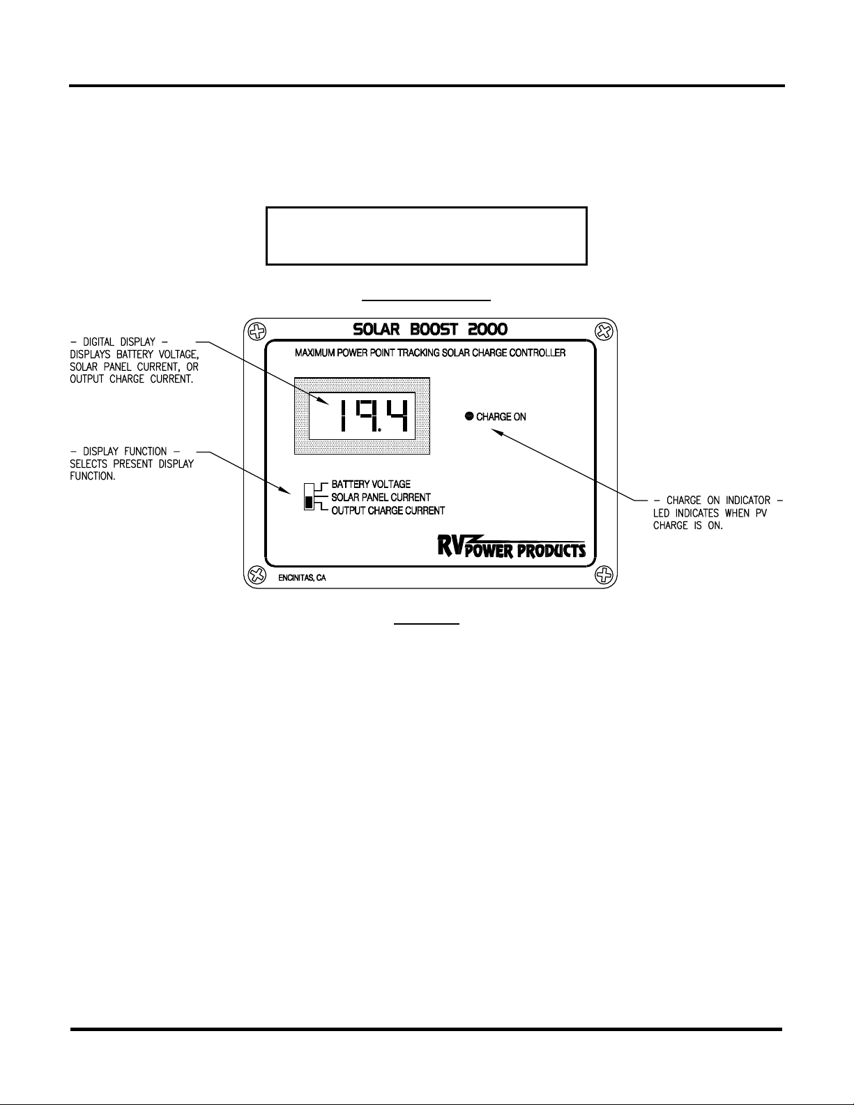
The highly accurate digital display consumes very little power and is always on and available for use. As
shown in Figure 1, the meter can be selected to display Solar Panel Current, Output Charge Current or Battery
Voltage. Solar Panel Current displays current in amps flowing from the PV array to Solar Boost 2000, whereas
Output Charge Current displays current in amps flowing from Solar Boost 2000 to the battery. When MPPT current
boost is functioning, Output Charge Current will be greater than Solar Panel Current. If operating conditions are
such that PV output power is insufficient for MPPT current boost to function, Output Charge Current may show 0.1
amps less than Solar Panel Current. This is normal as Solar Boost 2000 consumes approximately 0.090 amps to
operate when PV charge is on. When PV charge is off, standby current consumption is quite low at approximately
0.017 amps.
3
Page 5
Installation and Operation Manual
Battery Voltage displays battery voltage as measured at the Solar Boost 2000 battery terminals. The battery
voltage measurement system is highly accurate. However, when high charge current is delivered to the battery, the
displayed voltage will be somewhat higher than actual battery terminal voltage. This is due to voltage drop in the
wires between the Solar Boost 2000 and battery. Error can be minimized by using large low resistance wires and
connections to the battery as described in the Installation section. The displayed voltage will be highly accurate
when output charge current is low or zero.
The front panel serves as a heat sink for
power control devices. It is normal for the
front panel to be warm during operation.
PANEL LAYOUT
Figure 1
MAXIMUM POWER POINT TRACKING (MPPT)
MPPT and associated current boost operation is fully automatic and will function whenever sufficient PV
voltage and current are available. The percent increase you will receive in Output Charge Current relative to Solar
Panel Current is variable, and will change with operating conditions. When conditions are such that sufficient PV
voltage and current are not available to produce an increase in output current, Solar Boost 2000 will operate as a high
performance series pass PWM controller. Boost performance can be easily monitored using the digital display.
Whenever Output Charge Current is greater than Solar Panel Current, MPPT current boost is functioning. A minimum
PV current of just under one amp is required before MPPT can begin to operate.
The principal operating conditions which affect current boost performance are battery voltage and PV array
temperature. At constant solar intensity the power available from a PV array changes with PV array temperature. A PV
array’s power vs. temperature characteristic is such that a cool PV array can produce a higher voltage, and therefore
more power, than a hot PV array. When PV voltage is sufficiently high for MPPT to operate, Solar Boost 2000 delivers
a constant power output to the battery. Since output power is essentially constant while MPPT is operating, a decrease
in battery voltage produces a corresponding increase in charge current. This means that the greatest current increase
occurs with a combination of cool ambient temperature and low battery voltage. Solar Boost 2000 delivers the highest
charge current increase when you need it most, in cold weather with a discharged battery.
4
Page 6

RV Power Products - Solar Boost 2000
Because output power is constant while MPPT is operating, anything that leads to lower battery voltage will
produce an increase in Output Charge Current. While a discharged battery is one way to produce lower output voltage,
and therefore higher output current, other normal conditions may produce lower voltage as well. Any 12 volt power
consumption during the day will decrease net battery charge current, which decreases battery voltage. Operating a
large inverter to make coffee or run a microwave oven will produce substantial drops in output voltage leading to an
increase in output current. Additionally, anything that can be done to lower PV array temperature will also lead to an
increase in charge current by increasing PV power production. Locating the PV array in a breezy location for example
will cool the PV array due to increased air circulation.
TYPICAL CURRENT BOOST PERFORMANCE
As described above current boost performance for a particular installation varies with PV array temperature
and battery voltage. Two of the other primary factors which affect boost performance include system wiring and PV
panel design. The effect wiring has on performance is that power wasted heating undersized wiring becomes
unavailable for charging. The effect PV panel design has on performance is that panels with a maximum power voltage
) of 17 volts or greater will tend to produce more boost, whereas PV panels with VMP less than 17 volts will tend to
(V
MP
produce less boost. Additionally, more PV panels will tend to produce more boost, whereas fewer PV panels will tend to
produce less boost.
For a system using four 75 watt PV panels with peak power specifications of 4.45 amps @ 17 volts @ 25°C,
representative boost performance under a variety of operating conditions is shown in Table 1. Your current boost
performance will vary due to a variety of factors. W hat you can be sure of is that Solar Boost 2000 will automatically
deliver the highest charge current possible for a given installation and set of operating conditions.
TYPICAL CURRENT BOOST PERFORMANCE
FOUR 75 WATT PV PANELS
BATTERY CONDITION
AND VOLTAGE
FULLY DISCHARGED
10.9V
HIGHLY CHARGED
13.8V
HIGHLY DISCHARGED
11.8V
HIGHLY CHARGED
13.8V
AMBIENT
CONDITIONS
35°F
EARLY MORNING
45°F
CLOUDY, BREEZY
65°F
CLEAR, STILL AIR
75°F
CLEAR, STILL AIR
PV INPUT
CURRENT
8.8 AMPS 12.1 AMPS 38%
7.9 AMPS 9.3 AMPS 18%
16.7 AMPS 18.4 AMPS 10%
18.5 AMPS 18.5 AMPS 0%
OUTPUT CHARGE
CURRENT
PERCENT
INCREASE
TABLE 1
HOW MPPT AND CURRENT BOOST WORKS
A PV panel is a constant current type device. As shown on a typical PV panel voltage vs. current curve, current
remains relatively constant over a wide range of voltage. A typical 75 watt panel is specified to deliver 4.45 amps @ 17
volts @ 25°C. Traditional PV controllers essentially connect the PV array directly to the battery when battery voltage is
low. When this 75 watt panel is connected directly to a battery charging at 12 volts, the PV panel still provides
approximately the same current. But, because PV output voltage is now held at 12 volts by the battery rather than 17
volts, it only delivers 53 watts to the battery. This wastes 22 watts of available power.
Solar Boost 2000’s patent pending MPPT technology operates in a very different fashion. Under these
conditions Solar Boost 2000 calculates the maximum power voltage (V
available power, in this case 17 volts. It then operates the PV panel at 17 volts which extracts maximum power from the
PV panel. Solar Boost 2000 continually recalculates the maximum power voltage as operating conditions change. This
is referred to as Maximum Power Point Tracking (MPPT). Input power from the MPPT controller, in this case 75 watts,
feeds a switching type power converter which reduces the 17 volt input to battery voltage at the output. The full 75 watts
) at which the PV panel delivers its maximum
MP
5
Page 7

Installation and Operation Manual
which is now being delivered at 12 volts would produce a charge current of 6.25 amps. A charge current increase of 1.8
amps or 40% is achieved by converting the 22 watts that would have been wasted into useable charge current. Note
that this example assumes 100% efficiency to illustrate the principal of operation. In actual operation, boost will be
somewhat less as some available power is lost in wiring, connections, fuse and in Solar Boost 2000.
OPTIONAL TEMPERATURE COMPENSATION
The ideal charge voltage required by lead-acid batteries changes with battery temperature. Temperature
compensation of charge voltage leads to increased battery life and decreased battery maintenance. Fully automatic
temperature compensation of charge voltage can be provided through use of the optional SensorLug battery
temperature sensor, RVPP part number 930-0022-20. If your system includes this option, the charge voltage setpoint
will continuously adjust to the proper value based on measured battery temperature. Both liquid electrolyte and gel
electrolyte 12 volt lead-acid batteries require the same temperature compensation characteristic of is –30.0
millivolts/°C or –16.7 millivolts/°F. The graph of Figure 2 shows charge voltage setpoint vs. battery temperature for
the factory charge voltage setting of 14.0 volts @ 80°F. The slope of the voltage vs. temperature curve remains
constant for different 80°F voltage settings.
CHARGE VOLTAGE SETPOINT -VS.- BATTERY TEMPERATURE
Figure 2
OPTIONAL BATTERY MANAGER 6210 INTERFACE
Solar Boost 2000 may be fitted with an optional interface which allows it to operate as a fully integrated
power unit slave to an RV Power Products Battery Manager model 6210. If your Solar Boost 2000 includes this
interface, there will be two six pin connectors in the lower right hand corner of the circuit board as shown in Figure 3.
This interface can be added at any time. Contact RV Power Products for further information.
When combined with a 6210 control panel or complete 6210 system, Solar Boost 2000 no longer controls
the charging process but becomes a power unit slave to the advanced 6210 three stage charge controller. The 6210
control panel remotely measures battery terminal voltage, net battery current and battery temperature, and controls
a sophisticated three stage charge process which is precisely matched to battery electrolyte type and size in amphours. This charge regimen leads to the longest possible battery life while minimizing battery maintenance and
water loss. Note that when used with a 6210 controller, optional temperature compensation is not required since the
6210 performs this function.
6
Page 8

RV Power Products - Solar Boost 2000
CHARGE OPERATION WITH 6210 CONTROLLER
With Solar Boost 2000 integrated into a 6210 system, charge will begin whenever AC power, solar power or
both are available. Refer to the 6210 operators manual for a complete description of it’s sophisticated three stage
charge regimen. Note that the 6210 will transition from acceptance charge to float charge only when the battery is
truly fully charged, and not when charge current decreases to less than the full charge transition current due to low
solar intensity or high DC load during charge. Battery voltage displayed on Solar Boost 2000 may be slightly
different than that shown on the 6210 control panel when charge or discharge current is showing on either unit. This
is due to wiring resistance between Solar Boost 2000 and the battery. Due to the remote current and voltage
sensing provided by the 6210, it’s voltage measurement will be highly accurate at all times regardless of current.
INSTALLATION
WARNING: Read, understand and follow the Important Safety Instructions
in the beginning of this manual before proceeding. Adjustments or
connections other than those shown in Figure 3 void the limited warranty.
OVER VOLTAGE / REVERSE POLARITY PROTECTION
Solar Boost 2000 is fully protected against reverse polarity and high voltage transients for both the PV array
and the battery. If the battery is connected reverse polarity, Solar Boost 2000 will not operate and there will be nothing
shown on the display. If the PV array is connected reverse polarity, Solar Boost 2000 will not provide output current and
the PV input current display will show negative current. Should high PV current be available during reverse PV
connection the front panel will become quite warm but no damage to the unit will result.
Solar Boost 2000 is not protected against and will be damaged by
reverse battery connection to the PV terminals. Damage due to reverse
battery to PV terminals is not covered by the limited warranty.
ELECTROSTATIC HANDLING PRECAUTIONS
While transient voltage protection is provided for terminal block connections, exposed circuits may be
damaged by electrostatic discharge during installation and handling. Discharge yourself by touching a water faucet or
other electrical ground prior to handling the unit and avoid touching components on the circuit board. Keep Solar Boost
2000 in it’s electrostatic protective bag until the unit is installed. All electronic circuits may be damaged by static
electricity and these instructions combined with special packaging are provided to minimize the possibility of damage.
The risk of electrostatic damage is highest when relative humidity drops below 40%.
INSTALLATION STEPS
During installation you will:
• Setup Solar Boost 2000 operating mode
• Install Solar Boost 2000
• Connect Solar Boost 2000 to PV array and battery
• Install SensorLug battery temperature sensor (Optional)
• Connect to 6210 system (Optional)
SOLAR BOOST 2000 SETUP
If all of the factory default setup criteria listed below are correct, no further setup is necessary. If setup
modifications are necessary, modify the settings as identified in the following sections. There are 8 DIP switches and
two user adjustable potentiometers accessible on the rear of the controller that setup Solar Boost 2000 operation. Refer
to Figure 3 for switch and potentiometer locations.
7
Page 9

Installation and Operation Manual
Factory default setup criteria:
• Liquid electrolyte lead-acid battery
• Standalone operation (i.e. no optional 6210 controller)
• No temperature compensation (i.e. no optional SensorLug battery temperature sensor)
• Difference between PV open circuit voltage and maximum power voltage is 4.4V (V
OC-VMP
= 4.4V)
FACTORY DEFAULT SETUP
SWITCH1SWITCH2SWITCH3SWITCH4SWITCH5SWITCH6SWITCH7SWITCH
8
OFF
ON
BATTERY VOLTAGE
OFF
SETPOINT
ON ON ON
DIFFERENCE BETWEEN PV
VOC - V
MP
OFF
ON
14.0 V 4.4 V
TABLE 2
OPERATING MODE
Solar Boost 2000 will operate in one of three modes as shown below. Use the standalone mode when Solar
Boost 2000 is not used with RV Power Products Battery Manager model 6210 components. Note that switch #8 must
always be on.
SWITCH1SWITCH2SWITCH3SWITCH4SWITCH5SWITCH
OPERATING MODE
8
OFF
ON
OFF
ON ON ON
STANDALONE
(DEFAULT FACTORY
SETUP)
ON
OFF
ON
OFF
ON ON
6210 CONTROLLER
WITHOUT 6210 AC
CHARGER(S)
ON
OFF
ON
OFF OFF
ON
6210 CONTROLLER
WITH 6210 AC
CHARGER(S)
MPPT DISABLE
The MPPT function may be disabled if desired. To use Solar Boost 2000 with wind power generators or power
sources other than a PV array, disable peak power tracking. W ith peak power tracking disabled, Solar Boost 2000 will
operate as a series pass PWM type controller. Even if peak power tracking is disabled, PV array current will be less
than output charge current when battery voltage is at the desired setpoint due to the nature of Solar Boost 2000’s
power conversion technology.
SWITCH
MAXIMUM POWER POINT TRACKING
6
ON
ENABLED
OFF DISABLED
8
Page 10

RV Power Products - Solar Boost 2000
MAXIMUM POWER VOLTAGE
The nominal setting for this adjustment is the difference between the PV panel’s open circuit voltage (VOC)
and maximum power voltage (V
the rating label affixed to each PV panel. This value needs to be set correctly for the MPPT system to deliver
maximum current boost. The factory setting is 4.4 volts which is the appropriate value for many popular 36 cell PV
panels. These panels typically list V
). These voltage values are typically listed on both the PV panel datasheet and on
MP
at ≈21.4 volts and VMP at ≈17.0 volts, which yields; 21.4V - 17.0V = 4.4V.
OC
OPTIMIZING MPPT
The maximum power voltage setting (VOC - VMP) is a nominal value. The combined effects of manufacturing
tolerances in the PV panel and wiring resistance in a particular installation can sometimes shift the optimum setting.
While not required, it is recommended that for maximum boost performance this adjustment be fine tuned following
installation. Fine tuning is also desirable following installation of additional PV panels.
Fine tuning is easily accomplished by slowly adjusting the MPPT adjust potentiometer to obtain maximum
Output Charge Current. Adjustment is best done in full sun with a discharged battery and cool ambient
temperatures. Verify that a slight drop in output current is seen on either side of the peak. If a drop on either side of
the peak is not seen, MPPT is not fully operational due to a combination of high PV temperature and/or high battery
voltage. MPPT can usually be made to operate by lowering battery voltage through application of a heavy DC load.
If in doubt, leave the adjustment at the factory setting position as shown in Figure 3.
TEMPERATURE COMPENSATION
For temperature compensation to operate, the SensorLug battery temperature sensor must be installed and
temperature compensation must be enabled. Solar Boost 2000 will not provide output current if temperature
compensation is enabled without the SensorLug installed.
SWITCH
TEMPERATURE COMPENSATION
7
ON
ENABLED
OFF DISABLED
CHARGE VOLTAGE
The factory setting of approximately 14.0 volts is suitable for most liquid electrolyte batteries in a predominately
cycling application and does not require adjustment. For a predominately float application, a somewhat lower voltage of
perhaps 13.8 volts may be beneficial in decreasing water loss. If you need to change the setting, the adjustment
potentiometer location is shown in Figure 3. With the battery at or near full charge, adjust the charge voltage as
desired. First, verify that you are in the voltage control mode by momentarily setting the voltage somewhat higher than
your desired setting. If you cannot set the voltage higher, the battery is not sufficiently charged to be in the voltage
control mode. If a model 6210 charge controller is used, this adjustment will have no effect as the 6210 controls charge
voltage. If the SensorLug temperature compensation option is installed, first turn switch #7 off to disable temperature
compensation. The SensorLug does not need to be disconnected. Adjust the charge voltage to the desired 80°F value,
and then turn switch #7 back on.
SOLAR BOOST 2000 INSTALLATION
The Solar Boost 2000 panel should be mounted in a convenient location that provides easy routing of large
size wires to the PV array and battery, and keeps PV/battery wire length as short as practical. The location should also
provide free air circulation around the front of the panel, and if possible, around the rear. Take great care not to
damage circuit board components as this damage is not covered under the limited warranty. Figure 6 provides a 1:1
template for the panel cut-out. A surface mounting box is also available as RVPP part number 720-0011-01.
9
Page 11

Installation and Operation Manual
SOLAR BOOST 2000 SETUP ADJUSTMENTS AND FIELD CONNECTIONS
FIGURE 3
The front panel serves as a heat sink for power control devices and
requires free air circulation for cooling. Do not enclose the front
panel behind a tight fitting door or otherwise substantially restrict air
flow.
SYSTEM WIRING
Wiring requirements for Solar Boost 2000 are different than traditional PV controllers. While the performance
of other controllers may be affected somewhat by wiring, wiring and connections used with Solar Boost 2000 can have
a significant effect on current boost performance. Solar Boost 2000 increases charge current by transforming
previously wasted power into useable charge current. The effect wiring has on current boost performance is that power
wasted heating wires or connections is power that becomes unavailable to charge the battery. RV Power Products
offers a variety of low resistance installation and wiring kits to make installation easy and get the most out of your new
Solar Boost 2000.
10
Page 12

RV Power Products - Solar Boost 2000
A desirable installation would produce a total system wiring voltage drop of 0.6 volts or less, which can be
achieved using the wiring method shown in Figure 4 and wire sizes shown in Table 3. The wire lengths shown in Table
3 will provide a maximum voltage drop of 0.42 volts (4% of 14 volts), with the remainder of the 0.6 volts consumed by
connections fuse and so on. Note that lengths in Table 3 are shown for PV short circuit current values of 10 amps and
20 amps. For other values of PV short circuit current, maximum wire lengths scale inversely proportional to current,
such that half the current doubles the maximum wire length. For example, two 75W panels with I
be wired with up to 22.8 feet of 10AWG wire ((10 ÷ (4.45 x 2) x 20.3ft).
Table 3 is meant to serve as a wire size guide which will lead to good boost performance with reasonable wire
sizes. The lengths shown in Table 3 are one way from the PV array to the battery, with the Solar Boost 2000 placed
somewhere in the middle. Larger wire sizes will improve boost performance whereas smaller wire sizes will reduce
boost performance. When considering wiring, fuse, and connection options think big and short as larger heavier
components and shorter wire lengths offer less resistance and voltage drop. If the preferred wiring described here is
not practical or possible, Solar Boost 2000 will still function properly but current boost performance may be diminished.
= 4.45 amps could
SC
PREFERRED WIRING METHOD
Figure 4
The preferred wiring method shown in Figure 4 employs smaller wire sizes where necessary (roof wiring, panel
connections and fuse), and larger wire sizes where possible (long wire runs between PV array, panel and battery). Use
10AWG UV resistant cable to connect from the PV Panel(s) to the vicinity of the refrigerator vent or other connection
area, where the UV resistant 10AWG cable(s) connect to the PV conductor pair. As shown in Figure 4, short lengths of
10AWG wire should be used to connect this conductor pair to the Solar Boost 2000 terminal block. Figure 3 shows the
terminal block connections which will directly accept wire up to 10AWG. Connection to the battery is made in a manner
similar to PV wiring, except that a 30 amp fuse or circuit breaker must be installed in the positive wire near the battery.
Select a fuse holder with physically large internal components and a wire size of at least 12AWG.
11
Page 13

Installation and Operation Manual
MAXIMUM ONE WAY WIRE LENGTH FOR LESS THAN 0.42 VOLT DROP
WIRE GAUGE
AWG
12 AWG 6.4 / 2.0 12.8 / 3.9
10 AWG 10.2 / 3.1 20.3 / 6.2
8 AWG 16.2 / 4.9 32.3 / 9.0
6 AWG 25.7 / 7.8 51.4 / 15.7
4 AWG 40.8 / 12.4 81.7 / 24.9
2 AWG 64.9 / 19.8 129.9 / 39.6
1/0 AWG 103.3 / 31.5 206.7 / 63.0
MAX LENGTH @ 20 AMPS
FEET / METERS
MAX LENGTH @ 10 AMPS
FEET / METERS
TABLE 3
BATTERY TEMPERATURE SENSOR
The optional SensorLug battery temperature sensor (RVPP part number 930-0022-20) is used to control
charge voltage based on measured battery temperature. The SensorLug is electrically isolated and mounts directly to
any battery terminal. Note that connections are polarized (red/black), and must be connected as shown in Figure 3. For
temperature compensation to operate, it must be enabled as described in the Setup section.
INTEGRATING WITH BATTERY MANAGER 6210
Install Solar Boost 2000 as described above, and setup the operating mode for the desired Battery Manager
6210 components. The 6210 six pin control cable which connects between the 6210 control panel and the 6210 AC
charger unit(s) as described in the 6210 manual must route through Solar Boost 2000 as shown in Figure 5. Up to five
Solar Boost 2000’s can operate from a single 6210 control panel. To connect more than one Solar Boost 2000, the
wires of the six pin cable must be paralleled and feed the 6210 control in connector of each Solar Boost 2000. Any of
the Solar Boost 2000’s can provide the control out function to an AC charger unit. Note that for a 6210 AC charger to
operate there must be a 6210 control panel in the system.
The desired six pin cables can be provided by RV Power Products, or can be constructed from available
components. The cable(s) are pin-to-pin straight through, i.e. pin-1 to pin-1, pin-2 to pin-2, etc. for all six pins.
Connectors, pins and crimping tools can be purchased in small retail quantities from Mouser Electronics at 800-3466873 or on the web at www.mouser.com. Each connector end requires one connector P/N 538-39-01-2060, and six
pins P/N 538-39-00-0039. Use 22AWG wire or larger. Cables should be no longer that 30 feet.
BATTERY MANAGER 6210 INTERFACE
Figure 5
12
Page 14

RV Power Products - Solar Boost 2000
SPECIFICATIONS
Output current rating.................... 20A
System voltage ............................ 12V nominal
Max. PV Open circuit voltage ......30V
Max. battery voltage..................... 30V
Output current limit ...................... 21±1A
Volt meter full scale range ...........19.99V
Volt meter accuracy ..................... ±0.1% full-scale
Current meter full scale range ..... ±25A
Current meter accuracy ............... ±0.75% full-scale
Charge voltage adjustment .......... 13 - 15V typical
Power conversion efficiency ........94% typical @ 15A
Charge temp. coefficient. .............-16.7mV/°F
-30.0mV/°C
Current consumption
Standby...........................17mA typical
Charge on ....................... 90mA typical
Panel dimensions.........................4.6”Hx6.4”Wx1.8”D
THREE YEAR LIMITED WARRANTY
RV Power Products (hereinafter RVPP), hereby warrants to the original consumer purchaser, that the
product or any part thereof will be free from defects due to defective workmanship or materials for a period of three
(3) years subject to the conditions set fourth below. If within the coverage of this limited warranty, RVPP will repair or
replace the product at RVPP’s discretion. During year one (1), parts and labor are provided at no cost. During years two
(2) and three (3), parts are provided at no cost and labor is charged at RVPP’s prevailing labor rate. The original
consumer purchaser is responsible for all transportation costs and insurance.
1. This limited warranty is extended to the original consumer purchaser of the product, and is not extended to
any other party.
2. The limited warranty period commences on the date the product is sold to original consumer purchaser.
3. This limited warranty does not apply to any product or part thereof damaged by; a) alteration or
disassembly, b) repair or service not rendered by an RVPP authorized repair facility, c) accident or abuse,
d) corrosion, or e) operation or installation contrary to instructions pertaining to the product.
4. RVPP’s liability for any defective product or any part thereof shall be limited to the repair or replacement of
the product, at RVPP’s discretion. RVPP will not be liable for any loss or damage to person or property, or
any other damages, whether incidental, consequential or otherwise, caused by any defect in the product or
any part thereof. Some states do not allow exclusions or limitations of incidental or consequential damages,
so the above limitation may not apply to you.
5. Any implied warranty for merchantability or fitness for a particular purpose is limited in duration to the length
of this warranty. Some states do not allow exclusions or limitations on how long an implied warranty lasts,
so the above limitation may not apply to you.
6. This warranty gives you specific legal rights, and you may also have other rights which vary from state to
state.
7. To obtain warranty repairs, contact RVPP at 800-493-7877 or 760-944-8882 to obtain a Returned Goods
Authorization (RGA) number. Mark the outside of the package with the RGA number and return the product,
postage prepaid and insured to the address below. A copy of the purchase receipt identifying original
consumer purchaser must accompany the product to obtain warranty repairs.
RV Power Products
1058 Monterey Vista Way
Encinitas CA, 92024 USA
13
Page 15

Installation and Operation Manual
MOUNTING TEMPLATE (may not be 1:1 in printed PDF document)
Figure 6
14
 Loading...