

Page 1
Marine Electrical Prod
ucts
L-Series Solenoid Switch
with Coil Economizer
Features
• Hermetically sealed contacts • Vaporproof • Function as a remote battery switch
• Ignition protected - safe for installation aboard gasoline powered boats
• Pulse circuit requires low current draw when contact is closed
• UL Recognized - UL 508 Industrial Control Equipment
• Meets SAE J1171 - external ignition protection requirements
• Activated by an ON-OFF switch mounted anywhere
• Used as a manual battery paralleling switch • CE marked for EC applications
• Integrated coil control minimizes heating and amperage draw
Specications
Coil Circuit:
Input Voltage: 9 to 36 Volts Maximum
Power Consumption:
Inrush, 130ms: 3.8 Amperes@12-36 VDC
Holding 12 Volts: 0.13 Amperes@12 VDC
0.07 Amperes@24 VDC
Main Power Contacts:
Voltage Rating 60 Volts DC
Stud Terminal Size M8 (accepts 5/16” terminals)
Contact Form SPST-NO
Inrush Rating: 0.25sec. (10 repeats)* 2000 Amperes
Mechanical Life 1 Million Cycles
Make Current@10,000 Cycles: 2000 Amperes@28V
Break Current@10,000 Cycles: 2000 Amperes@28V
Wire Size Cranking Rating
9.75 sec. (10 repeats)*
1/0 500A 275A 250A
2/0 500A 400A 300A
2x2/0 800A 600A 450A
* Blue Sea Systems Engine Starting Standard
PN 9012
Intermittent Rating
5 min. (UL 1107)
Continuous Rating
(UL 1107)
Switch Ratings
The issue of switch ratings for engine starting is a tricky one. The reason
is that Underwriter’s Laboratories (UL), the only agency that establishes
standards for marine battery switch ratings, does not establish a standard
appropriate to engine starting situations. There are two ratings in the UL
marine battery switch standard, Intermittent and Continuous.
Intermittent is a 5 minute rating and is based on temperature rise of various
sections of the switch as the rated current is applied over a 5 minute period.
The Continuous rating is the same, but the time period is 1 hour.
As these standards demonstrate, there are three variables involved in
rating battery switches: time, current and temperature. For any given switch
the relationship of the variables is TEMPERATURE = TIME x CURRENT.
Clearly, neither of these ratings is applicable to engine starting situations
where the current draw is very high but the time period is very short,
typically 10 seconds or less. You will see some manufacturers rating their
switches at very high amperages, but close inspection will show that they
either fail to specify the time period or the time period is very short.
To correct this problem Blue Sea Systems has created an additional
standard to which its battery switches are rated. This standard is called the
Engine Start Standard and consists of ten 10-second cycles with a 2 second
rest between each cycle. The rst .25 seconds of the cycle is the Inrush
Current and the last 9.75 seconds of the cycle is the Cranking Current. The
Engine Start Standard is designed to represent a worst case engine starting
event in which the engine is cranked for 10 seconds, the ignition switched
off for 2 seconds to rest the battery and then repeated another 9 times.
Guarantee
Any Blue Sea Systems product with which a customer is not satised may
be returned for a refund or replacement at any time.
Blue Sea Systems Inc. Phone (360) 738-8230
425 Sequoia Drive Fax (360) 734-4195
Bellingham, WA 98226 USA E-mail conductor@bluesea.com
www.bluesea.com
8703 Rev. 010
Installation
Electrical Connections
1 Disconnect the positive battery connection before beginning the
installation. The wiring diagram is general in nature and is not meant to
be a guide for the wiring of any specic vessel. There are a wide range of
wiring congurations possible. Consult your marine electrical
professional for the wiring system applicable to your boat.
2 Make electrical connections based on the wiring diagram. Consult a wire
sizing chart to determine the appropriate wire sizes.
Main Disconnect and Starting Solenoids
High amperage electronic solenoid switches allow heavy cable runs to be
shortened dramatically by eliminating the need to route cables for
convenient operator access for manual switching operations. Shortened
cable runs save labor and material costs, reduce weight, conserve space,
reduce exposure to short circuits, and deliver higher circuit voltages.
Solenoid switches also allow high amperage switching operations to be
automated, allowing high amperage circuits to be completely disconnected
when not in use.
These switches can be used for:
1. Starting Circuit Disconnects
2. Main Distribution Panel Disconnects
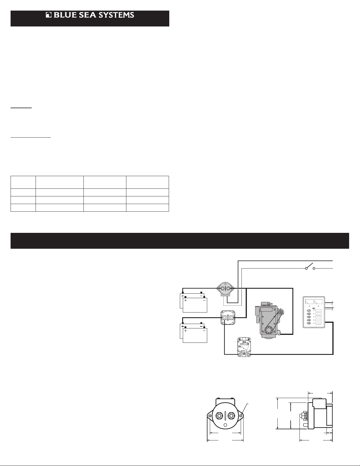
Electrical Connection Illustration
This schematic is to illustrate the general placement of the switch in a
circuit. It is not meant to provide detailed wiring instructions for any
particular boat.
Battery 1
Battery 2
BLACK WIRE
PN 9012
L-Series
Solenoid Switch
A1 A2
MINI SWITCH
9005 OR 9006
FOR EMERGENCY
CROSS CONNECT
BUSSMANN SERIES 187
CIRCUIT BREAKER
PN 9012 L-Series Solenoid Switch with Coil Economizer
RED WIRE
Engine
Wiring Diagram
MOUNTING HOLE
FOR #10 SCREW
Alternator
2.630"
66.80mm
Starter
2.300"
58.42mm
IGNITION SWITCH
"START" POSTION
MANUAL SPST SWITCH
DISTRIBUTION PANEL
OR
12�VOLT�DC�DISTRIBUTION
1 3
2
DC HOUSE
2.120"
53.85mm
TO DC
NEGATIVE
FROM DC
POSITIVE
OUT TO
DC LOADS
2.691"
68.35mm
3.170"
80.52mm
.500"
12.7mm
2.860"
72.64mm
 Loading...