

Blue Rhino GWU511A, GWU512A, GWU501E User Manual
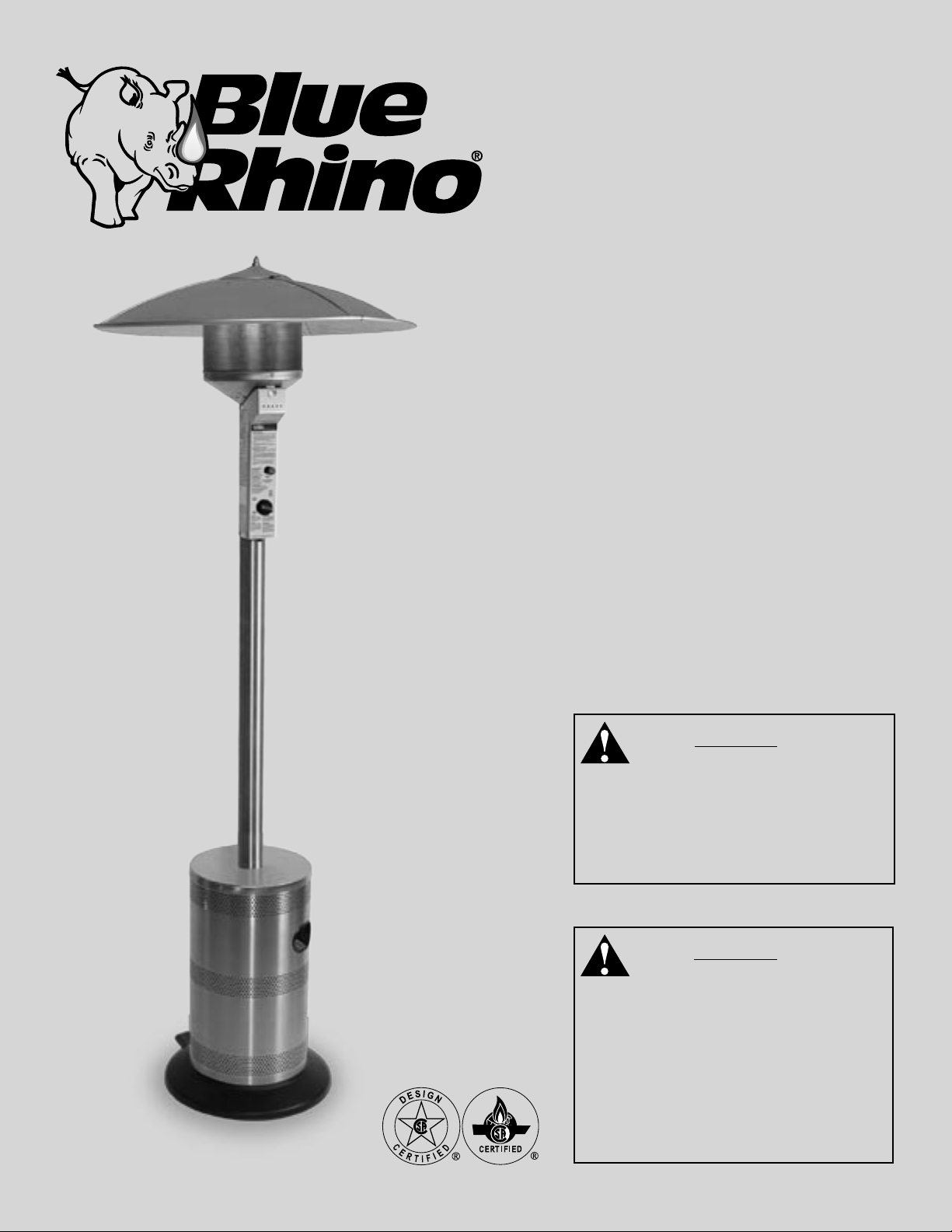
Owner’s Manual
Manual del Usuario
Model No.
GWU511A
U.S. Patent Number: 6,470,877; All Other Foreign
Patents May Apply.
WARNING
FOR YOUR SAFETY
For Outdoor Use Only
(Outside any enclosure)
Solamente Para Uso En Exteriores
(Fuera de cualquier recinto)
WARNING
FOR YOUR SAFETY
Improper installation, adjustment,
alteration, service or maintenance
can cause injury or property damage.
Read the installation, operation and
maintenance instructions thoroughly
before installing or servicing this
equipment.
Contact 1.800.762.1142 for assistance.
Do not return to place of purchase.
WARNING
FOR YOUR SAFETY
For Outdoor Use Only
(Outside any enclosure)
WARNING
FOR YOUR SAFETY
If you smell gas:
1. Shut off gas to the appliance.
2. Extinguish any open ame.
3. If odor continues, immediately call
your gas supplier.
WARNING
FOR YOUR SAFETY
WARNING
FOR YOUR SAFETY
Improper installation, adjustment,
alteration, service or maintenance
can cause injury or property damage.
Read the installation, operation and
maintenance instructions thoroughly
before installing or servicing this
equipment
WARNING
California Proposition 65:
Chemicals known to the state of
California to cause cancer, birth
defects, or other reproductive harm are
created by the combustion of propane.
1. Gas leaks may cause a re or
explosion which can cause serious
bodily injury or death, or damage to
property.
2. You must follow all leak checking
procedures as outlined in page 13
before operating this unit.
3. Never use an open ame to check for
leaks.
WARNING
FOR YOUR SAFETY
Do not store or use gasoline or other
ammable vapors or liquids in the
vicinity of this or any other appliance.
WARNING
FOR YOUR SAFETY
• Purchaser assumes all risk in the
assembly and operation of this
unit. Failure to follow this manual’s
WARNINGs and instructions can
result in severe personal injury, death
or property damage.
• Do not use in an explosive
atmosphere. Keep heater away from
areas where ammable liquids,
gasoline, vapors, or explosives are
stored or used.
1
Owner’s manual: model GWU511A outdoor patio heater
Contact 1.800.762.1142 for assistance.
Do not return to place of purchase.
Table of Contents
Safety First! . . . . . . . . . . . . . . . . . . . . . . . . . . . . . . . . . . . . . . . . . . . . . . . . . . . . . . . . . . . . . . 3
Assembly Instructions
Component Listing & Hardware . . . . . . . . . . . . . . . . . . . . . . . . . . . . . . . . . . . . . . . . . . . .5
General Components & Features . . . . . . . . . . . . . . . . . . . . . . . . . . . . . . . . . . . . . . . . . . 7
Additional Requirements . . . . . . . . . . . . . . . . . . . . . . . . . . . . . . . . . . . . . . . . . . . . . . . . 7
Step 1: Unpacking heater . . . . . . . . . . . . . . . . . . . . . . . . . . . . . . . . . . . . . . . . . . . . . . . .7
Step 2: Attach wheel assembly . . . . . . . . . . . . . . . . . . . . . . . . . . . . . . . . . . . . . . . . . . . 7
Step 3: Attach wheel assembly cover . . . . . . . . . . . . . . . . . . . . . . . . . . . . . . . . . . . . . . .8
Step 4: Attach legs . . . . . . . . . . . . . . . . . . . . . . . . . . . . . . . . . . . . . . . . . . . . . . . . . . . . .8
Step 5: Attach weight plate . . . . . . . . . . . . . . . . . . . . . . . . . . . . . . . . . . . . . . . . . . . . . .8
Step 6: Attach platform and post . . . . . . . . . . . . . . . . . . . . . . . . . . . . . . . . . . . . . . . . . . . 9
Step 7: Attach shroud cover . . . . . . . . . . . . . . . . . . . . . . . . . . . . . . . . . . . . . . . . . . . . . 9
Step 8: Attach engine . . . . . . . . . . . . . . . . . . . . . . . . . . . . . . . . . . . . . . . . . . . . . . . . . .10
Step 9: Attach gas line clip . . . . . . . . . . . . . . . . . . . . . . . . . . . . . . . . . . . . . . . . . . . . . 10
Step 10: Attach gas line/regulator assembly . . . . . . . . . . . . . . . . . . . . . . . . . . . . . . . . 10
Step 11: Assemble dome . . . . . . . . . . . . . . . . . . . . . . . . . . . . . . . . . . . . . . . . . . . . . . 11
Step 12: Attach dome . . . . . . . . . . . . . . . . . . . . . . . . . . . . . . . . . . . . . . . . . . . . . . . . . 11
Step 13: Insert battery . . . . . . . . . . . . . . . . . . . . . . . . . . . . . . . . . . . . . . . . . . . . . . . . 11
Install LP Gas Tank . . . . . . . . . . . . . . . . . . . . . . . . . . . . . . . . . . . . . . . . . . . . . . . . . . . .12
Check for Leaks . . . . . . . . . . . . . . . . . . . . . . . . . . . . . . . . . . . . . . . . . . . . . . . . . . . . . 13
Operation
Before Turning Gas Supply ON . . . . . . . . . . . . . . . . . . . . . . . . . . . . . . . . . . . . . . . . . . 14
Before Lighting . . . . . . . . . . . . . . . . . . . . . . . . . . . . . . . . . . . . . . . . . . . . . . . . . . . . . . 14
Lighting . . . . . . . . . . . . . . . . . . . . . . . . . . . . . . . . . . . . . . . . . . . . . . . . . . . . . . . . . . . 14
Re-Lighting . . . . . . . . . . . . . . . . . . . . . . . . . . . . . . . . . . . . . . . . . . . . . . . . . . . . . . . . . 15
Shutdown . . . . . . . . . . . . . . . . . . . . . . . . . . . . . . . . . . . . . . . . . . . . . . . . . . . . . . . . . . 15
Operation Checklist . . . . . . . . . . . . . . . . . . . . . . . . . . . . . . . . . . . . . . . . . . . . . . . . . . . 16
Troubleshooting . . . . . . . . . . . . . . . . . . . . . . . . . . . . . . . . . . . . . . . . . . . . . . . . . . . . . . . . . . 17
Maintenance . . . . . . . . . . . . . . . . . . . . . . . . . . . . . . . . . . . . . . . . . . . . . . . . . . . . . . . . . . . . . 18
Storage . . . . . . . . . . . . . . . . . . . . . . . . . . . . . . . . . . . . . . . . . . . . . . . . . . . . . . . . . . . . . . . . . 19
Service . . . . . . . . . . . . . . . . . . . . . . . . . . . . . . . . . . . . . . . . . . . . . . . . . . . . . . . . . . . . . . . . . 19
Warranty . . . . . . . . . . . . . . . . . . . . . . . . . . . . . . . . . . . . . . . . . . . . . . . . . . . . . . . . . . . . . . . . 20
Specifications . . . . . . . . . . . . . . . . . . . . . . . . . . . . . . . . . . . . . . . . . . . . . . . . . . . . . . . . . . . . 21
The use and installation of this product must conform to local codes. In absence of local codes, us
the National Fuel and Gas Code, ANSI Z223, 1/NFPA 54, Storage and Handling of Liquid Petroleum
Gases, ANSI/NFPA 58 or CSA B149.1, Natural Gas and Propane Installation Code.
Owner’s manual: model GWU511A outdoor patio heater
Save these instructions for future
reference. If you are assembling this
unit for someone else, give this
manual to him or her to
save for future reference.
2
Contact 1.800.762.1142 for assistance.
Do not return to place of purchase.
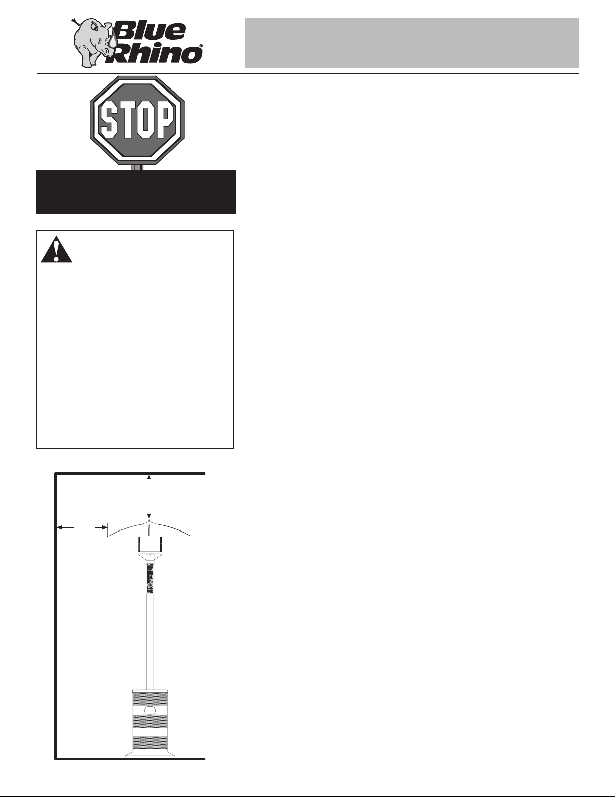
Safety First!
Read and become familiar with this entire manual, especially the following precautions.
If you are unsure of anything in these instructions, STOP and contact
1.800.762.1142 for assistance.
Before you do anything else,
read and understand all
precautions in Safety First!
WARNING
FOR YOUR SAFETY
• Purchaser assumes all risk in the
assembly and operation of this
unit. Failure to follow this manual’s
WARNINGs and instructions can
result in severe personal injury,
death or property damage.
• Do not use in an explosive
atmosphere. Keep heater away
from areas where ammable
liquids, gasoline, vapors, or
explosives are stored or used.
Ceiling or Overhang
36”
24”
Caution: This appliance is for outdoor use only (outside any enclosure). Always
make sure there is fresh air ventilation.
• Always maintain at least 36” clearance (top) and 24” clearance (side) from combustible
materials.
• Always place heater on a hard and level surface.
• Do not use if the wind velocity is greater than 10 miles per hour.
• Unit will operate at reduced efficiency below 40ºF (5ºC).
• Keep sprinklers and other water sources away from burner and controls.
• Always use extreme caution when near heater. Alert both children and adults
to the hazards of high temperatures, especially to avoid burns or clothing
catching fire.
• Young children and pets should be carefully supervised when they are in the area
of heater.
• Do not hang clothing or other flammable materials either on or near heater.
• Any guard or other protective device removed for servicing the heater must be
replaced prior to operating the heater.
• Certain materials or items, when stored under heater, will be subjected to radiant heat
and could be seriously damaged.
• Do not alter heater in any manner.
• The pressure regulator and hose assembly supplied with the appliance must be used
and replacements must be those specified by the manufacturer.
• Inspect heater before each use. If a damaged part is detected, do not operate until an
original equipment replacement part has been properly installed. Use of unauthorized
parts will void warranty and create an unsafe condition.
• Do not attempt to use this appliance without a functional factory-supplied gas regulator
in place. If regulator becomes damaged, use only a factory-supplied replacement.
• Prior to operating heater, replace any guards or protective devices removed for
servicing.
• During operation, do not touch burner assembly. The surface of heater’s emitter can
Wall
3
reach temperatures approaching 1600ºF.
• After shutdown, do not touch burner assembly until heater has cooled (approximately
45 minutes after use).
Notice: This product should not be used with any fuel other than liquid propane. Use of
other fuels will detract from heaters performance and will void your warranty.
Caution: Liquid propane (LP) gas is flammable and hazardous if handled
improperly. Become aware of the characteristics before using any LP product.
• LP Characteristics – Flammable, explosive under pressure, heavier than air - settles in
pools in low areas.
Owner’s manual: model GWU511A outdoor patio heater

Contact 1.800.762.1142 for assistance.
Do not return to place of purchase.
• In its natural state, propane has no odor. For your safety, an odorant is added that
smells like rotten cabbage.
• Contact with LP can cause freeze burns to skin.
• This heater is shipped from the factory for LP gas use only.
• Use only Department of Transportation (DOT) approved “20 lb.” LP gas tanks (same
as those commonly used on gas grills) with Acme / Type 1 / QCC safety valves. These
valves can be quickly identified because they have external and internal threads.
• Never use an LP tank with a damaged body, valve, collar, or footring.
• Dented or rusted LP tanks may be hazardous and should be checked by your LP
gas supplier.
• The tank supply system must be arranged for vapor withdrawl.
• The tank used must include a collar to protect the tank valve.
• When heater is not in use, turn LP tank OFF.
• Always perform a leak test on gas connections whenever a tank is connected. Never
use a flame to test for leaks. Do not smoke while performing a leak test.
Caution: It is essential to keep the heater’s valve compartment, burners, and
circulating air passages clean.
• Spiders and insects can create a dangerous condition that may damage heater or make
it unsafe. Keep burner area clean of all spiders, webs, or insects.
• Inspect heater before each use.
• Have heater inspected annually and repairs should be made by a qualified
service person.
• Check heater immediately if any of the following conditions exist:
• The smell of gas in conjunction with extreme yellow tipping of burner flames.
• Heater does not reach proper temperature.
Note: At temperatures less than 40ºF, heat output will be reduced.
• Heater’s glow is excessively uneven
• Burner makes popping noises during use.
“20 lb.” LP Tank
Valve
18”-19”
Collar
Body
Foot
FOR YOUR SAFETY:
Beware of Spiders
Spiders or small insects can get into the
burner tube or other openings of your
heater, and spin webs or build nests.
These obstructions can lead to gas
ow problems. It is important to make
frequent inspections of these areas and
clean them when necessary.
Before operating your heater for the rst
time, be sure to check for obstructions
that may have occurred during
shipment.
Note: A slight pop is normal when burner is extinguished.
• Carbon deposits may create a fire hazard. Keep dome and emitter clean at all times.
• Do not clean heater with combustible or corrosive cleaners. Use warm, soapy water.
• Do not paint engine, engine access panel or dome.
Owner’s manual: model GWU511A outdoor patio heater
Need a tank of LP gas?
Try Blue Rhino tank exchange service. It’s easy,
fast, safe, and available at tens of thousands of
conveniently located retail outlets nationwide. You
can purchase a new full tank or exchange your
empty for a precision filled one.
For your nearest Blue Rhino retailer visit
www.bluerhino.com.
4
Contact 1.800.762.1142 for assistance.
Do not return to place of purchase.
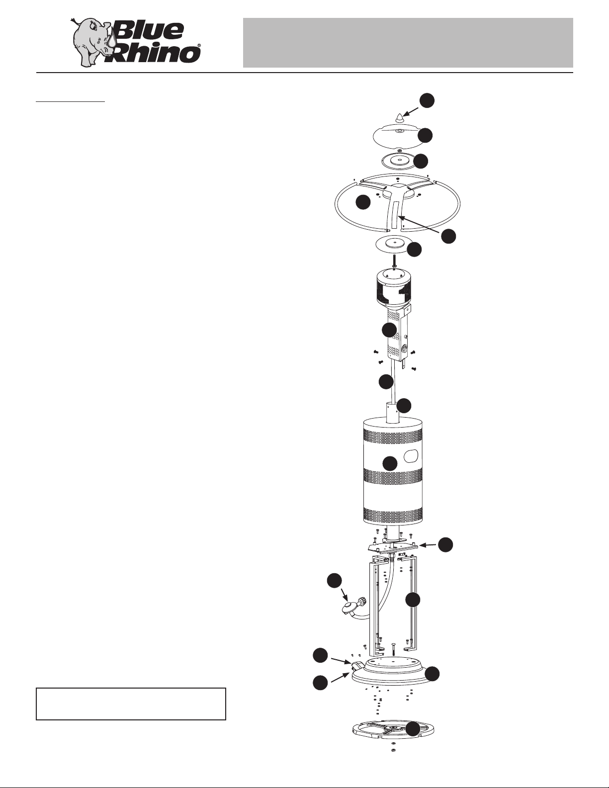
Components
1. Finial . . . . . . . . . . . . . . . . . . . . . . . 56-01-103
2. Dome Cap . . . . . . . . . . . . . . . . . . . 56-01-104
3. Dome Plate . . . . . . . . . . . . . . . . . . . 56-01-105
4. Dome Panel (3) . . . . . . . . . . . . . . . . 56-01-107
5. Dome Rib (3) . . . . . . . . . . . . . . . . . 56-01-109
6. Bottom Plate . . . . . . . . . . . . . . . . . . 56-01-111
7. Emitter Assembly . . . . . . . . . . . . . . 56-01-118
8. Gas Line . . . . . . . . . . . . . . . . . . . . 56-01-351
9. Pole . . . . . . . . . . . . . . . . . . . . . . . 56-01-354
10. Shroud . . . . . . . . . . . . . . . . . . . . . 56-01-164
11. Platform . . . . . . . . . . . . . . . . . . . . 56-01-353
12. Regulator Hose Assembly . . . . . . . 56-01-355
13. Legs (3) . . . . . . . . . . . . . . . . . . . . 56-01-193
1
2
3
4
5
6
7
8
9
14. Wheel Assembly . . . . . . . . . . . . . . 56-01-360
15. Wheel Assembly Cover . . . . . . . . . 56-01-361
16. Base . . . . . . . . . . . . . . . . . . . . . . 56-01-350
17. Weight Plate . . . . . . . . . . . . . . . . . 56-01-359
For a complete list of components, please visit
www.bluerhino.com
10
11
12
13
15
16
14
17
5
Owner’s manual: model GWU511A outdoor patio heater
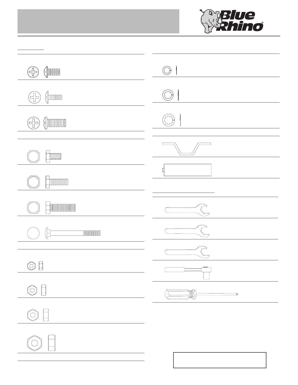
Hardware
7/16"
Contact 1.800.762.1142 for assistance.
Do not return to place of purchase.
A Small Screw 3 pcs
5/32” - 32 x 8 Stainless Steel Round Head Screw
B Medium Screw 6 pcs
3/16” - 24 x 15 Black Zinc Plated Philips Head Screw
C Large Screw 4 pcs
1/4” - 20 x 16 Stainless Steel Philips Head Screw
D Small Bolt 3 pcs
1/4” - 20 x 15 Nickel Plated Hex Head Bolt
E Medium Bolt 12 pcs
1/4” - 20 x 20 Nickel Plated Hex Head Bolt
F Dome Bolt 1 pc
3/8” - 16 x 35 Stainless Steel Hex Head Bolt
L Small Lock Washers 4 pcs
ø5 Nickel Plated Lock Washer
M Medium Lock Washer 15 pcs
ø6 Nickel Plated Lock Washer
N Large Lock Washer 1 pc
ø10 Nickel Plated Lock Washer
O Gas Line Clip* 1 pc
P AA Battery* 1 pc
Hardware Not Included
Q 7/16” Wrench 1 pc
G Carriage Bolt 1 pc
3/8” - 16 x 95 Nickel Plated Hex Head Bolt
H Small Nut 4 pcs
3/16” - 24 Nickel Plated Hex Nut
I Medium Nut 18 pcs
1/4” - 20 Nickel Plated Hex Nut
J Large Nut 1 pc
3/8” - 16 Stainless Steel Hex Nut
K Extra Large Nut 1 pc
3/8” - 16 Nickel Plated Hex Nut
R 9/16” Wrench 1 pc
S 3/4” Wrench 1 pc
T 7/16” Socket and Socket Wrench 1 pc
U #2 Phillips Head Screwdriver 1 pc
Owner’s manual: model GWU511A outdoor patio heater
For a complete list of hardware, please visit
www.bluerhino.com
6
Contact 1.800.762.1142 for assistance.
Do not return to place of purchase.
Assembly Instructions
General Components & Features
Familiarize yourself with all components before proceeding. Refer to page 5 for hardware and components, and page 21 for specifications.
Do NOT attempt assembly unless all components are available. If you believe a component is missing or damaged, contact 1.800.762.1142 for
assistance.
Note: All hardware is mounted on a cardboard pack and numbered to match their assembly step.
Additional Requirements
The following items are not included, but are necessary for the proper assembly of your heater. Do NOT attempt to assemble without proper tools.
(1) Leak Detection Solution (Instructions on how to make solution are included in “Checking for Leaks” section)
(1) Precision Filled LP Gas Grill Tank with Acme Type 1 external threaded valve connection (4-5 gallon size)
Note: You must follow all steps to properly assemble heater.
Typical assembly: approximately 1 (one) hour.
Image shown
from bottom
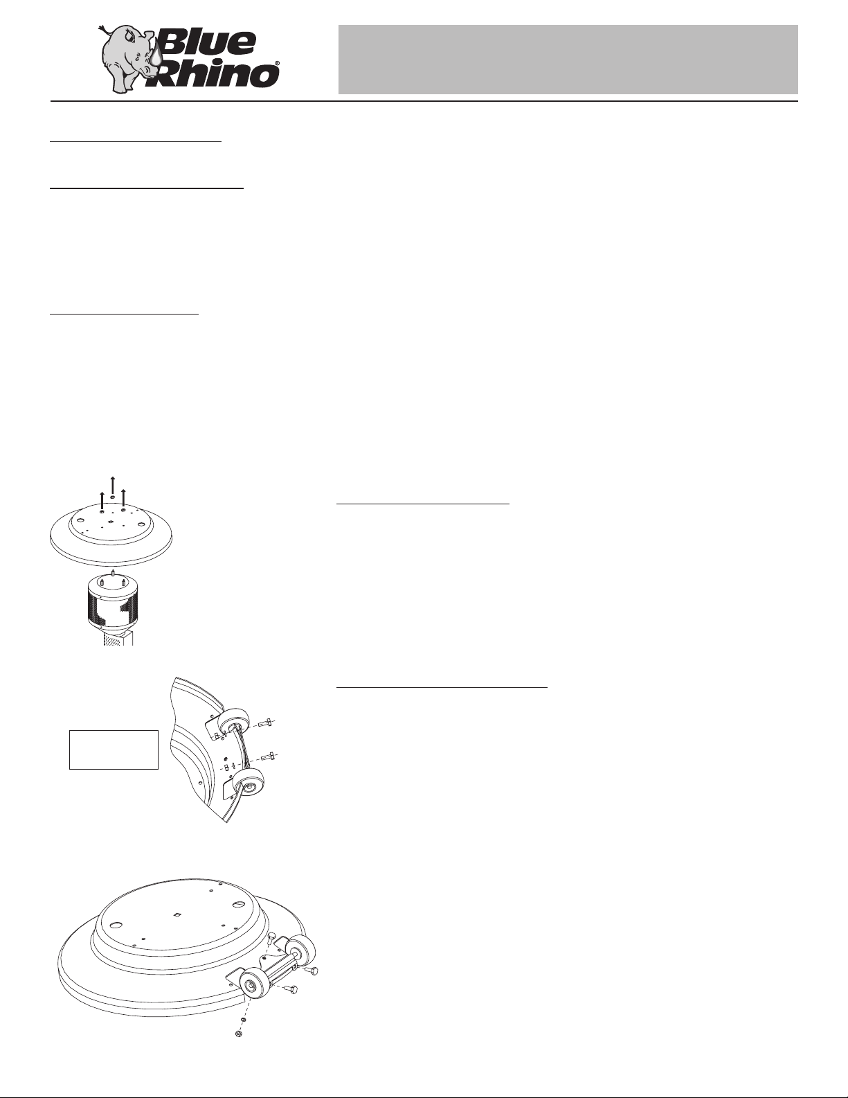
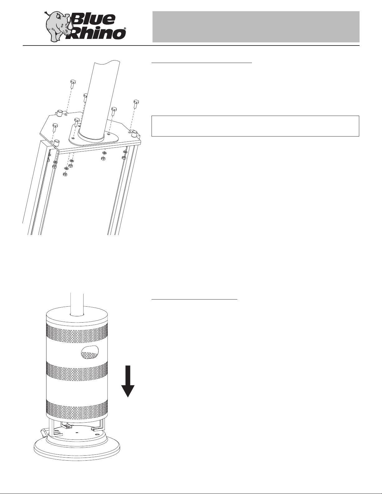
Step 1: Unpacking heater
Note: When unpacking your heater from the carton, you will find that the engine assembly
and the base have been bolted together for shipping purposes.
Remove the three nuts at the top of the base and separate the engine from the base.
Note: Retain these nuts as you will use them later.
Step 2: Attach wheel assembly
A. Attach wheel assembly to base using 3 sets of small bolt (D), medium lockwasher (M),
medium nut (I).
B. Tighten bolts once all bolts are in place.
7
Owner’s manual: model GWU511A outdoor patio heater
Contact 1.800.762.1142 for assistance.
Do not return to place of purchase.
Step 3: Attach wheel assembly cover
A. Attach wheel assembly cover to base using 4 sets of medium screws (B), small lock
washers (L), small nut (H).
B. Tighten screws once all screws are in place.
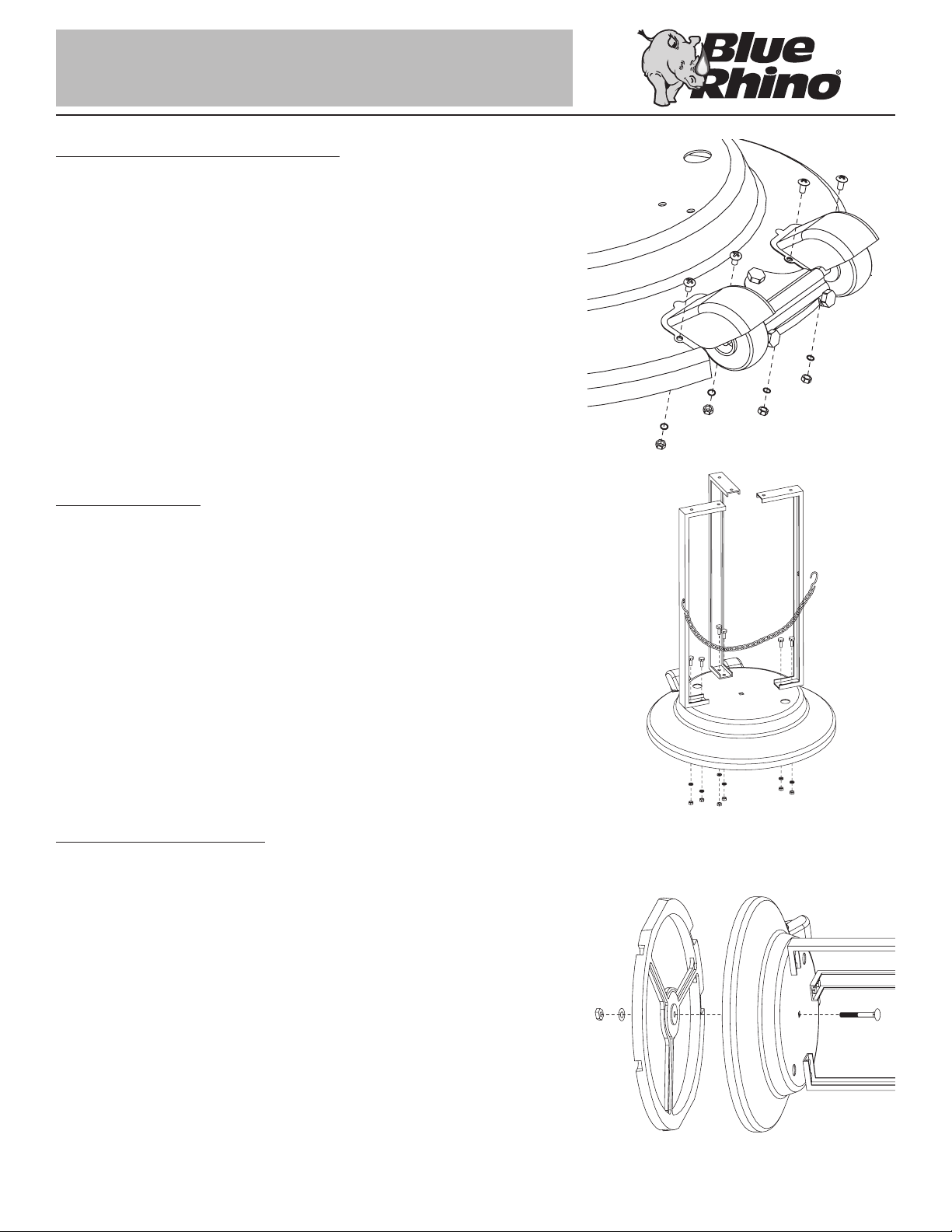
Step 4: Attach legs
A. Attach legs to base using 6 sets of medium bolt (E), medium lockwasher (M), and
medium nut (I). Finger tighten only.
Note: Do not fully tighten until Step 6.
B. Attach small ‘S’ hook on Tank Restraint Chain to left leg.
Step 5: Attach weight plate
A. Lay base assembly on its side.
B. Insert weight plate into base, feet out. Secure using a 9/16” wrench, and 1 set of
carriage bolt (G), large lock washer (N), and extra large nut (K).
Note: If you plan to anchor your heater permanently, be sure to line up two outer holes in
base with those in weight plate so that your anchor bolt will pass through both holes.
C. Place base assembly upright.
Owner’s manual: model GWU511A outdoor patio heater
8
Contact 1.800.762.1142 for assistance.
Do not return to place of purchase.
Step 6: Attach platform and post
A. Attach platform to legs using 7/16” wrench, 3 sets of medium bolt (E), medium
lockwasher (M), medium nut (I).
B. Attach post to platform using 7/16” wrench, 3 sets of medium bolt (E), medium
lockwasher (M), medium nut (I).
C. Fully tighten all nuts and bolts from Step 4.
TIP:
To tighten use a 7/16” wrench on Bolt and a 7/16” socket wrench on Nut.
Step 7: Attach shroud cover
Slide shroud cover over pole and base assembly until bottom of shroud rests on base.
9
Owner’s manual: model GWU511A outdoor patio heater
Contact 1.800.762.1142 for assistance.
Do not return to place of purchase.
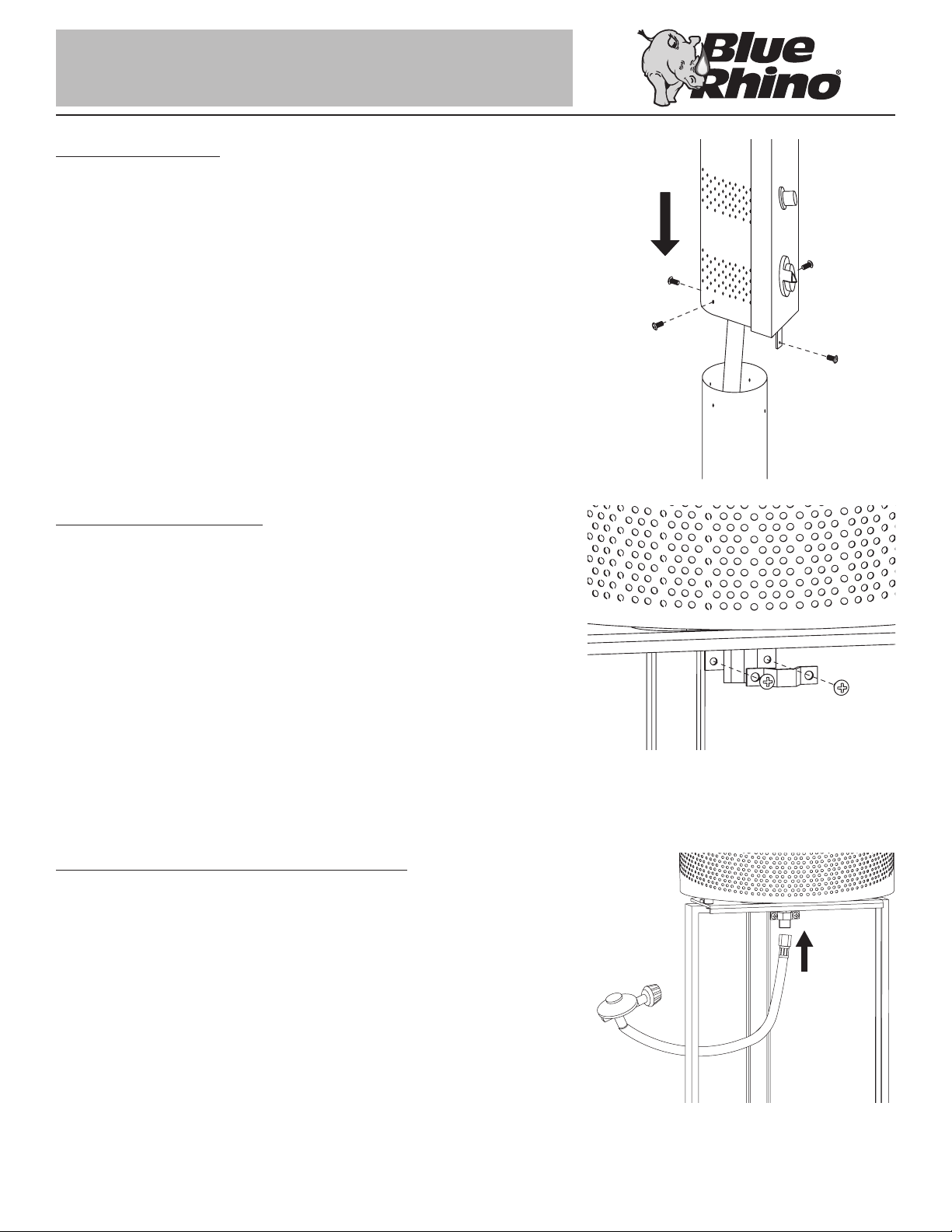
Step 8: Attach engine
A. Lay engine assembly and base assembly on their side, using carton for support.
B. Insert gas line through pole.
Note: Make sure gas line comes out bottom of pole before securing engine to pole.
C. Attach engine to post using 4 large screws (C).
Note: Do not fully tighten screws until all screws are inplace.
Step 9: Attach gas line clip
A. Lift shroud cover to expose platform.
B. Make sure gas line feeds through indent in gas line clip.
C. Attach gas line clip (O) to base platform using 2 medium screws (B), securing the gas
line without damaging the exposed bolts.
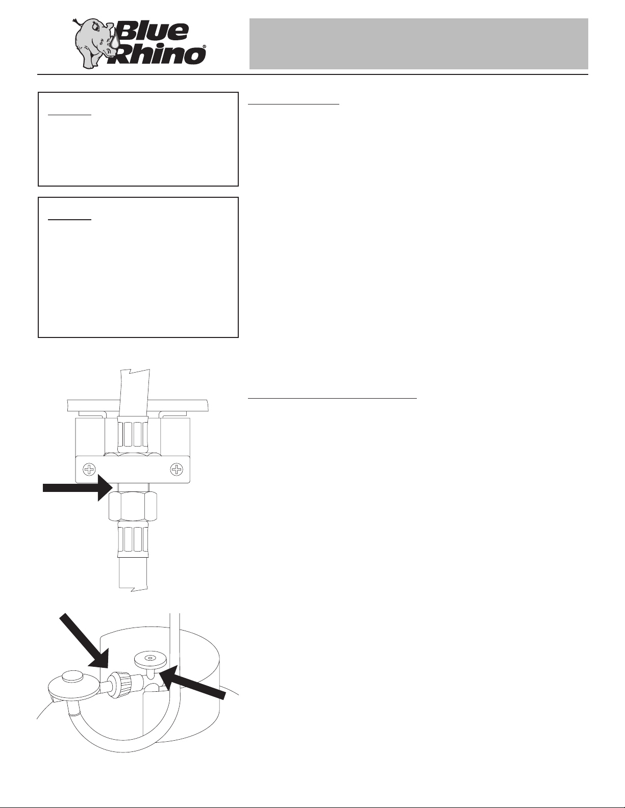
Step 10: Connect gas line/regulator assembly
Attach gas line/regulator assembly to gas line using 3/4” wrench.
Owner’s manual: model GWU511A outdoor patio heater
10
Contact 1.800.762.1142 for assistance.
Do not return to place of purchase.
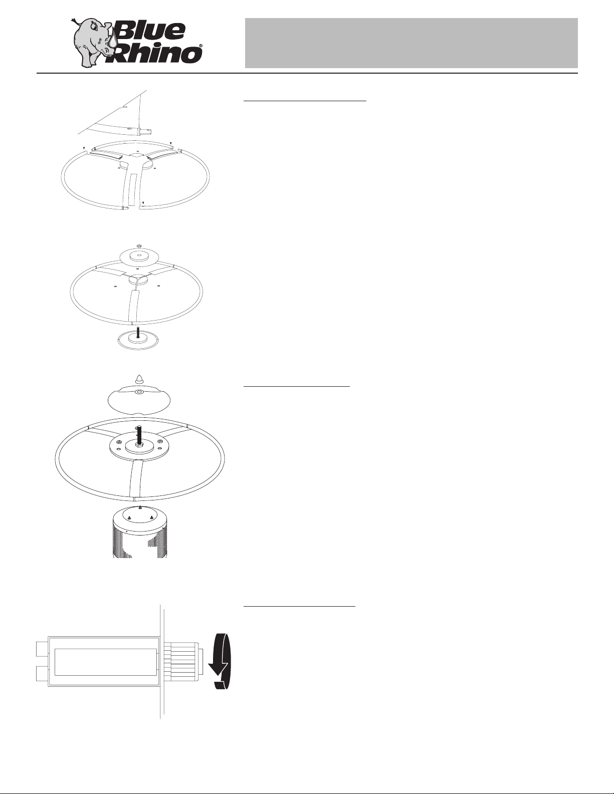
Step 11: Assemble Dome
Note: Each dome section has a pin mounted in the rolled bottom edge. If necessary for
proper alignment of dome sections, loosen each screw prior to assembly.
A. Slide dome rib onto pin side of dome panel.
B. Slide two dome panels togther. Secure with small screw (A).
C. Repeat procedure for all three dome panels.
D. Insert dome bolt (F) through dome plate, dome, top dome plate, large nut (J).
E. Tighten all screws on dome panels.
Step 12: Attach dome
A. Attach dome to emitter using 3 medium nuts (I).
B. Attach dome cap to dome assembly using finial.
Step 13: Insert Battery
A. Remove battery cap.
B. Insert 1 AA battery (P).
C. Replace battery cap.
11
Owner’s manual: model GWU511A outdoor patio heater
Contact 1.800.762.1142 for assistance.
Do not return to place of purchase.
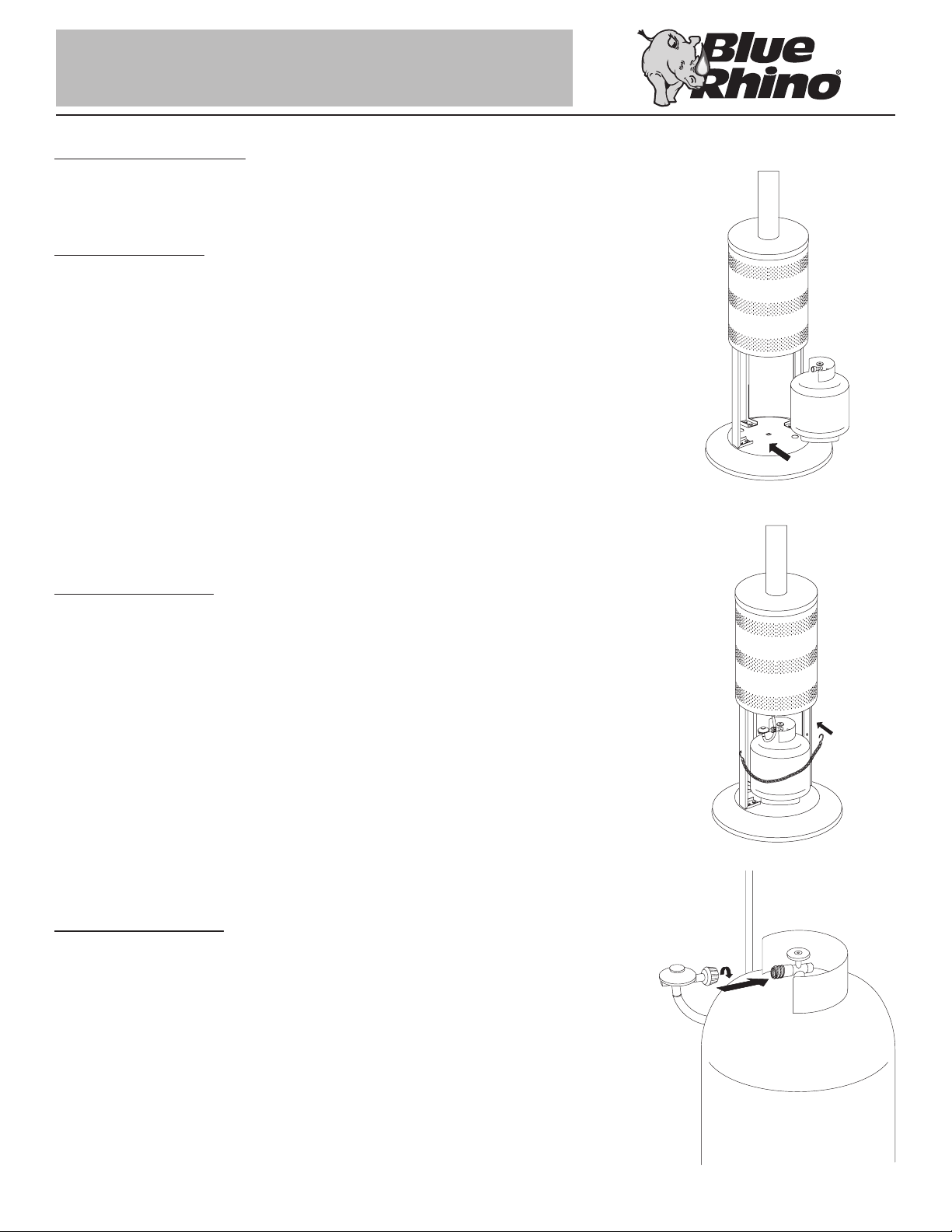
Installing LP Gas Tank
To operate you will need (1) precision-filled standard grill LP gas tank (20#) with external valve
threads.
Insert LP Gas Tank
Place precision filled LP gas tank into heater base upright so it is arranged for vapor
withdrawal.
Secure LP Gas Tank
Secure tank in place by attaching loose end of tank restraint chain to hole in right leg.
Connect LP Gas Tank
Before connecting, be sure that there is no debris caught in the head of the gas tank, head
of the regulator valve or in the head of the burner and burner ports.
Connect gas line to tank by turning knob clockwise until it stops.
Owner’s manual: model GWU511A outdoor patio heater
12
Caution
Before you attempt to use a propane
tank, understand all tank and
propane related precautions in
Section #1: “Safety First.”
Caution
Your Blue Rhino® Heater has been
checked at all factory connections
for leaks. Recheck all connections,
as movement in shipping can loosen
connections. Check for leaks even if
your unit was assembled for you at
the store.
Contact 1.800.762.1142 for assistance.
Do not return to place of purchase.
Check for Leaks
• Make 2-3 oz. of leak check solution by mixing one part liquid dishwashing soap and
three parts water.
• Turn tank valve ON.
• Check Gas Line / Control Valve for leaks:
• Spoon several drops of solution onto gas line and control valve connection.
• Inspect the solution at the connection to look for bubbles.
• If NO bubbles appear, then the connection is secure.
• If bubbles appear, there is a leak -
• Turn tank valve OFF.
• Loosen screw on clip.
• Release gas line fitting from control valve and re-attach making sure connection is
secure.
• Retighten clip.
• If you continue to see bubbles after several attempts, contact 1.800.762.1142 for
assistance.
Check Gas Line / Tank valve for leaks:
• Turn tank valve ON.
• Spoon several drops of solution onto gas line and tank valve connection.
• Inspect the solution at the connection to look for bubbles.
• If NO bubbles appear, then the connection is secure.
• If bubbles appear, there is a leak:
• Turn tank valve OFF.
• Release gas line fitting from tank valve and re-attach making sure connection is
secure.
• If you continue to see bubbles after several attempts, contact 1.800.762.1142 for
assistance.
• Turn Tank Valve OFF.
13
Owner’s manual: model GWU511A outdoor patio heater
 Loading...