

Page 1
Serial No.
OPERATOR AND
INSTALLATION MANUAL
MODELS
TC35270 & TC35160
BLUE OX®
ONE-YEAR LIMITED WARRANTY
Page 1 of 7 292-6090 Rev. K 5/30/12
©2012 Blue Ox
One Mill Road, Industrial Park
Pender, Nebraska 68047
Phone 402-385-3051
Toll Free 888-425-5382
Fax 402-385-3360
www.blueox.com
Page 2

BLUE OX ORIGINAL PURCHASERS
ONE YEAR LIMITED WARRANTY
Automatic Equipment Manufacturing Company (“Automatic”) warrants to the original (rst) retail purchaser that
this product, manufactured by Automatic, shall be free from defect in material and workmanship under normal
use and service for a period of one years from the date of delivery.
During said one-year period, Automatic will repair or replace any parts that have been returned by the original
purchaser, to the factory, transportation prepaid, and in Automatics sole and absolute opinion found to be
defective.
Limitations on Warranty Coverage:
Coverage under this warranty will be valid only if the customer warranty card is returned by the original
purchaser within 30 days of purchase.
Coverage under this warranty will be effective only when a copy of the original invoice, showing date and place
of purchase, accompanies any claim for warranty. This warranty is NON TRANSFERABLE.
This limited warranty will not cover, in any way or form, any alleged damages caused by incorrect or improper
installation, improper use, modication or neglect of product, failure to properly service and maintain, misuse,
act of God, accident or failure of the user to follow guidelines contained in the instructional material provided by
Automatic.
This warranty does not cover normal wear and tear, paint or rust.
Warrantor assumes no responsibility to the owner for loss of use of product, loss of time, inconvenience or
any other damage consequential or otherwise. Including, but not limited to mileage, expense of transporting
of product, return shipping expense, mechanics travel time, telephone, road service, towing, and rental during
repairs, travel, lodging, loss or damage to personal property or loss of earnings.
REPAIR OR REPLACEMENT AS SET FORTH IN THIS LIMITED WARRANTY IS THE SOLE EXCLUSIVE REMEDY OF
THE PURCHASER. AUTOMATIC SHALL NOT BE LIABLE FOR ANY INCIDENTAL OR CONSEQUENTIAL DAMAGES
FOR BREACH OF ANY EXPRESS OR IMPLIED WARRANTY ON THIS PRODUCT. EXCEPT TO THE EXTENT
PROHIBITED BY APPLICABLE LAW, ANY IMPLIED WARRANTY OF MERCHANTABILITY OR FITNESS FOR A
PARTICULAR PURPOSE ON THIS PRODUCT IS LIMITED IN LENGTH TO THE DURATION OF THIS WARRANTY.
Some states do not allow the exclusion of incidental of consequential damages, or allow limitations on how long
an implied warranty lasts, so previous limitations or exclusions may NOT apply to you. This warranty gives you
specic legal rights and you may also have other rights which vary from state to state.
Automatic reserves the right to make changes or add improvements to its product at any time without any
obligation to make such changes to previously manufactured equipment.
No liability is assumed for bodily injury that may be inicted on the purchaser, operator, spectator or general
public who is in the general area while this equipment is in use.
WARRANTY REQUEST PROCEDURE:
If your Automatic product develops a defect during the warranty period, promptly notify Automatic Customer
Care. Until such notice is received, Automatic will not be responsible for any repairs or replacement.
Upon receipt of notice from you, Automatic will have a choice of options in repairing or replacing any part it
determines in its sole and absolute desecration to be defective. 1.) Customer Care may require you, at your
own expense, to deliver or ship the part to the factory for evaluation. They will issue a “Return Merchandise
Authorization” (RMA) number if this is required.
2.) Any part that is, in Automatic’s sole and absolute judgment, found to be defective in material or workmanship,
will be repaired or replaced, at Automatic’s option without charge for parts or labor. At Automatic’s option, new,
refurbished or improved parts may be used in the repair or replacement of warranted items or replacement
products.
Blue Ox® Division
Automatic Equipment Mfg. Co.
P.O. Box 430
Pender, Nebraska 68047
www.blueox.com - (402) 385-3051
Pender, Nebraska 68047
Page 2 of 7 292-6090 Rev. K 5/30/12
Page 3
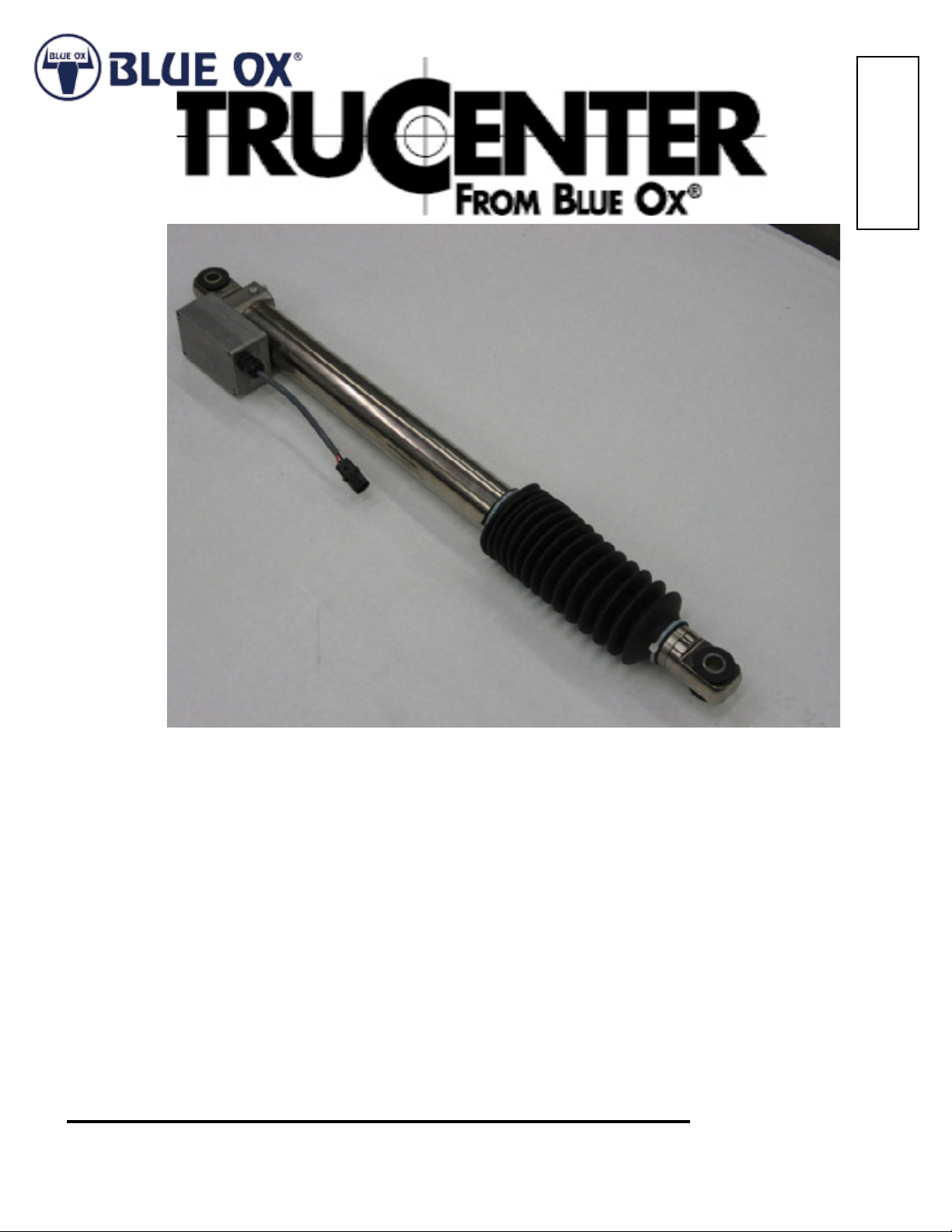
TruCenterTM Steering Control System
Installation Instructions
TC35160 Steering Control
TC35270 Steering Control
Review the TruCenter application guide to verify you have selected the proper TruCenter steering control
system for your vehicle. Over or under-sizing the TruCenter may cause improper handling characteristics.
READ THESE AND MOUNTING BRACKET INSTRUCTIONS COMPLETELY BEFORE STARTING THIS
INSTALLATION.
DEALER or INSTALLER:
Be certain the user receives the
instruction sheets for their products.
Install this unit using the proper TruCenter™ bracket kit for your vehicle
(sold separately). This unit may also be installed on existing SAFE-TPLUS™ brackets on your vehicle. Inspect your existing brackets for
possible damage or wear before reusing with the TruCenter.
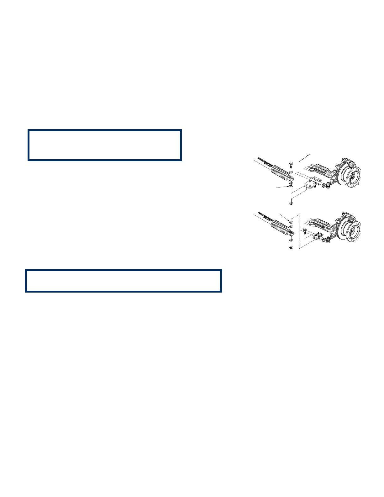
SHIM
Figure 1
FRONT OF VEHICLE
SHIM
NOTE:
The TruCenter is meant to be mounted parallel with and in back of the tie
rod. It may be necessary to use shims between the tie rod bracket
and the TruCenter unit (see Figure 1). Shimming the TruCenter unit in
this fashion allows clearance and keeps it from binding.
Be sure the mounting brackets for the unit are parallel.
1. Location of the tie-rod bracket must be adjusted to t the TruCenter. Before installing, verify the TruCenter
unit is still in adjustment from the factory by ensuring:
The distance from center to center at the TruCenter mounting points is
approximately 35” ± 1/32”. If this is not the case, continue installation then refer to realigning the TruCenter.
2. Ensure the vehicle’s front wheels are straight ahead before starting
installation. The vehicle must be at normal ride height, (i.e., air bags lled to
normal driving height). Do not use jacks or levelers. Install the TruCenter
with the adjustable end (solenoid end) mounted to the anchor bracket.
Mount the other end on the tie-rod bracket. See the instructions that came
with the mounting brackets for proper location of brackets.
3. See wiring diagram on page 3 for proper wiring of the TruCenter™ unit and use
as a reference for instructions A – E below.
Page 3 of 7 292-6090 Rev. K 5/30/12
Page 4

Figure 2
A. Route the two-wire harness from the TruCenter up to the motor home’s front hood area. Locate a keyed 12-
volt power source and a ground point.
CAUTION:
Leave enough slack in the wire to allow for axle movement and ensure that a 12-volt circuit is used.
B. Locate a convenient place on the dash or side control panel to mount the TruCenter switch. The switch
should be in a location easily accessed by the driver. Place the small TruCenter decal next to the switch
(room permitting) for identication.
C. Locate a convenient location (out of sight) close to where the switch will be installed. Mount the solid-
state timer relay at this location using a zip tie or ¼” self-tapping screw. If mounting the relay with a screw,
make sure you know what you are drilling into. Next, run the black and red TruCenter wires up to the relay
mounting location. Cut the red wire at a length necessary to reach the relay. Crimp on a female terminal
connector. Plug the red wire onto the N.C. terminal on the relay.
D. Identify a suitable ground. Ground both the black wire going to the TruCenter solenoid and the negative
power input terminal on the relay. Use the necessary connectors supplied to do this.
E. Using the extra red wire and the in-line fuse connector, tie into a keyed 12-volt power source. Connect
the opposite end onto one side of the switch. Using the remaining red wire, plug into the open terminal
of the switch. On the opposite end, create a small pigtail and plug into the positive power input and COM
terminals on the relay.
F. Insert 15-amp fuse. Lastly, test the solenoid by supplying power, bumping the switch and listening for the
“click”.
Page 4 of 7 292-6090 Rev. K 5/30/12
Page 5

Realigning Center
NOTE:
One person can re-align the TruCenter, but it is easier with at least two people.
After installation is complete, realign the TruCenter as follows: While depressing the dash-mounted button,
make trim adjustment with the steering wheel, either right or left, until the center to center distance of the
mounting holes is 35 inches (See Figure 2).
After the 35 inch center to center distance is obtained, loosen the tie rod bracket u-bolts (See Figure 1).
Center and align the front wheels, assuring that the tie rod bracket slides along the tie rod and that the
center to center distance of the mounting holes remains at 35 inches, then tighten the tie rod bracket
u-bolts.
1. After installing the TruCenter unit, turn the steering wheel to both the right and left extremes to ensure
the motor home’s structure does not interfere with any of the TruCenter components and that the TruCenter
unit in no way limits the turning capabilities of the motor home.
Verify the t so that under no circumstances the
steering or suspension movement is limited.
NOTE:
THIS IS EASIEST DONE WITH TWO PEOPLE—ONE TURNS THE STEERING WHEEL WHILE THE OTHER
OBSERVES THE MOVING COMPONENTS. Next, dump the air from air bags and check that the motor
home’s structure does not rest on any part of the TruCenter components.
2. If the wheels were nearly straight when the TruCenter was installed, no mechanical adjustment should be
required.
Operating Instructions
With these TruCenter models, (TC35270 & TC35160) the operator has the ability to adjust the length or center
point of the TruCenter unit. If the vehicle tends to pull to one side, the operator needs to push the TruCenter
switch and hold it in while turning the steering wheel in the direction that makes the vehicle follow a straight
path. Then, release the switch. For example, if encountering a high crosswind, depress the switch while
correcting the vehicle’s course by turning the steering wheel into the wind. Only turn the steering wheel
enough to make the vehicle follow a straight path down the road. When the wind stops push the button,
steer the coach so it is going straight and release the button.
CAUTION:
THE SWITCH ACTIVATES A SOLENOID THAT, IF ACTIVATED TOO LONG, CAUSES PERMANENT
DAMAGE TO THE SOLENOID. THE TIMER RELAY IS PROPERLY SET AT THE FACTORY. ALTERING
STANDARD FACTORY SETTING WILL CAUSE IMPROPER FUNCTION OF TRUCENTER AND/OR
PERMANENT DAMAGE TO THE SOLENOID.
Although a timer relay is installed to protect the solenoid, we recommend NOT activating the solenoid for
periods longer than 5 to 10 seconds at a time. It is better to make multiple, ne adjustments than to hold
the switch and try to align in one, time-consuming operation.
NOTE:
THE ADJUSTMENT BUTTON ONLY ALLOWS THE ADJUSTMENT TO BE MADE WITH THE STEERING
WHEEL. IT ACTIVATES AN ADJUSTABLE GAS SPRING—BUT THE ACTUAL ADJUSTMENT MUST BE
MADE BY MANUALLY TURNING THE STEERING WHEEL TO THE DESIRED POSITION.
Page 5 of 7 292-6090 Rev. K 5/30/12
Page 6

RV Straight Axle Alignment
With a TruCenter
There are three alignment settings that are adjustable with your RV.
Caster, Camber, and Tow In!
Caster will cause a pull right of left, but will not cause tire wear.
Camber will cause tire wear, but will not cause a pull.
Tow In will cause tire wear, but will not cause a pull.
Most customers think that if their coach doesn’t pull one way or the other it is aligned properly. Not so! There
are a lot of shops that only set the Tow In because they don’t have the equipment to bend, or shim the axle!
This will not x the problem if the camber is out of spec. The axle will need to be bent.
These are the common practices to acquire proper alignment:
To adjust the caster you must install tapered shims between the axle and the spring or air bag support.
To adjust the camber you must bend the axle.
To adjust the Tow In you must loosen the tie rod ends and turn the tie rod in or out.
The TruCenter will not affect the alignment on any coach but it can make the alignment last longer as it will
absorb the shock when a chuck hole or a curb is hit. The TruCenter will not change the alignment.
Note to Alignment Technician concerning the Pre-alignment Procedure for the RV’s with TruCenter application:
1. With a TruCenter on the RV the Alignment Technician should rst make sure the TruCenter is centered.
2. Technician must remove the two small U-bolts that hold the TruCenter to the tie rod.
3. Strap the TruCenter up out of the way with zip ties.
4. Align the RV to spec.
5. Reinstall the TruCenter on the tie rod with the U-bolts.
6. The TruCenter will need to be centered. The Technician will need to adjust the TruCenter 35 inches
center to center between the two large ¾ inch bolts. Have someone in the RV turn steering wheel while the
Technician measures the required 35 inches. When the measurement is conrmed, press the TruCenter control
button in the RV and then release the button.
7. Loosen the U-bolts from the TruCenter so that it can slide on the tie rod.
8. Steer the front wheels so they are straight forward and reinstall the TruCenter on the tie rod with the Ubolts.
CAUTION:
The TruCenter must be centered at 35 inches between the two ¾ inch bolts. Failure to do this could
cause an accident, injury or death.
Page 6 of 7 292-6090 Rev. K 5/30/12
Page 7

Tools Required
3
5
1
4
FRONT OF VEHICLE
2
9/16” Socket 3/8” Drive Ratchet 1 1/8” Socket 1 1/8” Wrench
NOTE:
Chassis and bracket installation shown may
vary slightly from your individual installation.
TruCenterTM unit orientation shown may be rotated
180 degrees from your individual installation. Refer
to the bracket kit instructions included with your
application.
Parts List
Ref. No. Qty. Part No. Description
1 1 TC35160 TruCenterTM Steering Control
or TC35270 TruCenterTM Steering Control
2 1 62-3631 Weather Tight Cord
3 2 201-0847 3/4”-10 x 3-1/2” Hex Bolt, Grd. 5
4 8 203-0007 3/4” Flat Washer, ZP (Required)
5 2 202-0074 3/4”-10 Flange Whiz Lock Nut
IMPORTANT:
Use only genuine factory replacement parts on your bracket kit. Do not substitute homemade
or non-typical parts. If a bolt is lost or in need of replacement, for your safety and the preservation of your bracket kit, be sure to use a replacement bolt of the same grade. Repair parts may
be ordered through your nearest Blue Ox dealer or distributor.
Page 7 of 7 292-6090 Rev. K 5/30/12
 Loading...