

Page 1

RECREATIONAL
VEHICLE LOADER
OPERATOR, PARTS AND
INSTALLATION MANUAL
SC9028
SC9029
(43” Tire Width
Golf Cart Dolly)
SC9030
(49” Tire Width
Golf Cart Dolly)
Page 2
1 of 6 292-2840 Date 02/07
Page 3
Ref. No. Qty. Part # Description
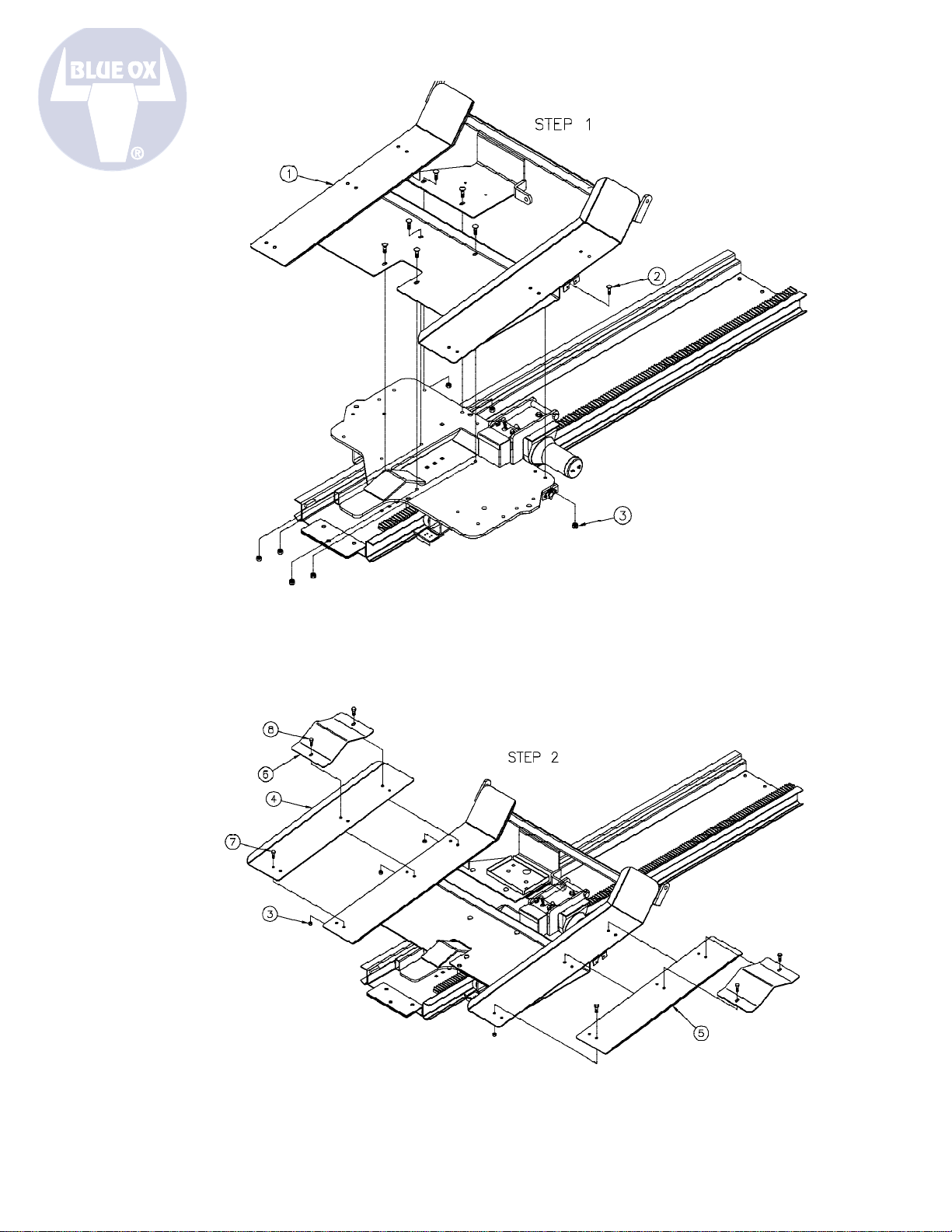
1 1 61-6256 Weldment, Golf Cart Loader, SC9028
2 7 201-0008 3/8-16x1 1/4” Carriage Bolt, GRD. 5, ZP
3 14 202-0090 3/8-16 Hex NYL. Lock Nut
4 1 101-6934 Ramp, ADJ., DS SC9028
5 1 101-6935 Ramp, ADJ., PS SC9028
6 2 101-6936 Tire Support, SC9028
7 3 201-0443 3/8-16x1” Hex Bolt, GRD. 5, ZP
8 4 201-0034 3/8-16x1” Carriage Bolt, GRD. 5, ZP
2 201-0192 10-32x1/2” Slot, RD. HD. Screw
2 203-0054 #10 Lock Washer
2 202-0047 #10-32 Hex Nut
2 101-5822 Adapter, 4 Way Connector
1 225-0051 Clamp Loop, 1/4” ID
1 201-0071 1/4-20X1” Hex Bolt GRD. 5, ZP
1 203-0001 1/4” Flat Washer, ZP
1 202-0102 1/4-20 Hex Nylon Nut, ZP
1 62-3603 43” Dolly Cross Member, SC9029 (Optional)
1 62-3614 49” Dolly Cross Member, SC9030 (Optional)
WARNING
!
- USE ONLY GENUINE FACTORY
REPLACEMENT PARTS -
Do NOT substitute homemade or non-typical parts.
This may cause your carrier to fail and result in injury
or death. If repair parts or components are needed,
you may order them through your nearest Blue Ox®
Dealer or Distributor, or call our 24/7 Customer Care
Team at (402) 385-3051.
Date 02/07 292-2840 2 of 6
Page 4

DO NOT INSTALL OR USE THIS EQUIPMENT
UNTIL THE FOLLOWING OPERATING AND
INSTALLATION INSTRUCTIONS HAVE BEEN
READ AND UNDERSTOOD.
INSTALLATION OF THE
RECREATIONAL VEHICLE LOADER
1
1. Unhook red and black wiring from battery (see
white arrows). Pull both wires back through holes
and to the winch (see grey arrows).
3
3. Using two 3/4” wrenches, remove the bolt
from the cargo buckle bracket attached to the
cycle slide head assembly. Using a 3/4” and
5/8” wrench, remove one cargo buckle from the
bracket and set the cargo buckle aside to be
reinstalled in a different location. The second
cargo buckle and both brackets are not used with
the SC9028 and can be stored away.
2
2. Remove battery box from tray and then using
a 7/16” wrench, remove two bolts from the battery
tray. Set battery box, tray and bolts aside to be
reinstalled in a different location.
3 of 6 292-2840 Date 02/07
4
4. Using a 9/16” wrench, remove ve 3/8”
carriage bolts from the bull dog jack assembly.
The jack assembly and bolts are not used with
the SC9028 and can be stored away.
Page 5

5
5. Position the holes on the golf cart loader
weldment, so they line up with the cycle slide
head assembly. Insert a 3/8-16x1 1/4” carriage
bolt into each of the seven holes and then tighten
down with a 3/8-16 hex nylon lock nut, using a
9/16” wrench.
6. Relocate battery box and tray to area shown
in picture 6A (see white arrow). Run battery
wires from winch to new location of battery and
reattach. Place a clamp loop in area shown
in picture 6B (see grey arrow). Using a 7/16”
wrench, secure it in place with a 1/4-20x1” hex
bolt, 1/4” at washer and 1/4-20 hex nylon nut.
7
7. Using a 5/8” and 11/16” wrench, secure the
cargo buckle set aside in Step 3, to the tab
located near the battery box.
6A
6B
8
8. Place adjustable driverside ramp (101-6934)
and passenger side ramp (101-6935) on there
respected side of the golf cart loader weldment.
The holes on the ramp should match up with the
holes on the weldment, according to the golf cart
tire width. For a 43” tire width, see white arrows
on picture above. For a 49” tire width, see grey
arrows on the picture above.
Date 02/07 292-2840 4 of 6
Page 6

9
9. After ramp is in place, position tire support
(101-6936) on ramp, so holes line up. Insert a
3/8-16x1” carriage bolt into the top two holes (see
grey arrows) and a 3/8-16x1” hex bolt into the
bottom hole (see white arrow), then tighten down
with a 3/8-16 hex nylon lock nut, using a 9/16”
wrench. Do this to both sides of the golf cart
loader weldment.
10
10. Before the golf cart can be loaded into
the pickup, you must attach a golf cart dolly to
the back. It is the customers responsibility to
specify which golf cart dolly they need (SC9029
& SC9030), when purchasing the golf cart
loader. Using a 9/16” deep socket, secure the
dolly cross member assembly to the leaf spring
with two 3/8-16x3 1/2”x2” u-bolts (201-0697) and
four 3/8-16 hex nylon lock nuts (202-0090). You
will then need to adjust the dolly cross member
so it’s straight. The golf cart is then ready to
be winched up into the back of the pickup. It is
then the responsibility of the customer to use
additional tie downs where needed.
5 of 6 292-2840 Date 02/07
Page 7

6 of 6 292-2840 Date 02/07
Page 8

To nd the Blue Ox dealer nearest you,
visit www.blueox.com or call 888-425-5382.
Serial Number
 Loading...