

Page 1
TM
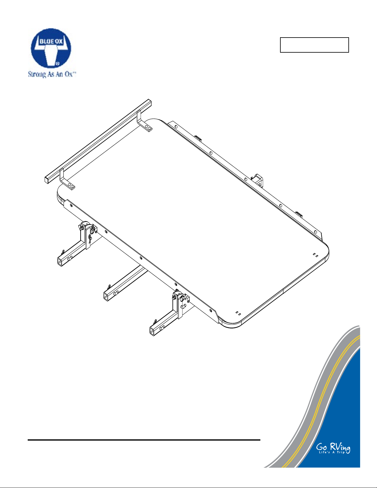
SportCarrier I
Serial No.
TM
OPERATOR, PARTS AND
INSTALLATION MANUAL
SC2100
SportCarrier I
© 2011 Blue Ox Division, Automatic Equipment Mfg. Co. • One Mill Road, Industrial Park • Pender,
Nebraska 68047 • Phone 402-385-3051 • Fax 402-385-3360 • www.blueox.com
TM
Page 2

TM
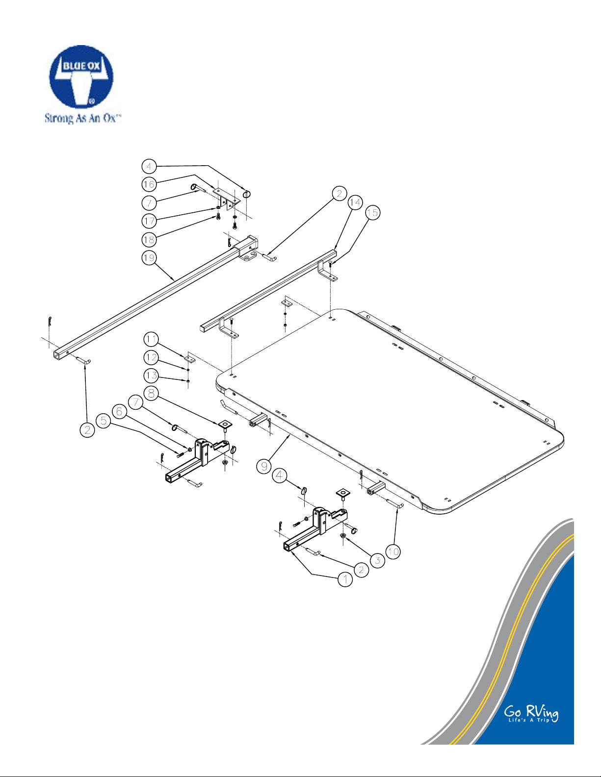
Parts List
Ref. No. Qty. Part No. Description
1 2 61-6073 .........................................................................Wldm't, Deck Support
2 4 200-1483 ...............................................................Pin, 5/8" x 3" eff. w/clip, ZP
3 2 202-0073 ...................................................... 5/8-11 Hex Flange Whiz Nut, ZP
4 3 84-0001 ............................................................................Quick Pin Assembly
5 2 201-0323 ...................................1/2-13 X 1 3/4" Square Head Cap Set Screw
6 2 202-0072 ......................................................1/2-13 Hex Flange Whiz Nut, ZP
7 3 229-0520 ..................................................................Pin, 1/2" x 2 5/8" eff. , ZP
8 2 299-0509 ....................................................................... Adjuster, SC2100, ZP
9 1 61-6080 ..........................................................Wldm't, Deck, SC2100/SC2101
10 2 200-1701 ...............................................................Pin, 5/8" x 4" eff. w/clip, ZP
11 2 102-6593 .....................................................................................Flat, Tirestop
12 4 203-0010 .........................................................................3/8" Lockwasher, ZP
13 4 202-0003 ...........................................................................3/8-16 Hex Nut, ZP
14 1 61-6092 ................................................................................ Wldm't, Tire Stop
15 4 201-0008 ................................. 3/8-16 x 1 1/4" Carriage Head Bolt, Grd.5, ZP
16 1 61-6077 .......................................Wldm't, Hold Up Bracket, Center Extension
17 2 203-0012 .........................................................................1/2" Lockwasher, ZP
18 2 201-0011 ..........................................1/2-13 x 1 1/4" Hex Head Bolt, Grd.5, ZP
19 1 61-6048 ................................................................... Wldm't, Center Extension
© 2011 Blue Ox Division, Automatic Equipment Mfg. Co. • One Mill Road, Industrial Park • Pender,
Nebraska 68047 • Phone 402-385-3051 • Fax 402-385-3360 • www.blueox.com
Page 1 of 14 292-2710 Rev A 10/21/11
Page 3
TM
IMPORTANT: Use only genuine factory replacement parts on your SportCarrier I™. Do
not substitute homemade or nontypical parts. If parts are lost or in need of replacement,
for your safety and the preservation of your SportCarrier I, order replacement parts through
your nearest Blue Ox dealer or distributor.
© 2011 Blue Ox Division, Automatic Equipment Mfg. Co. • One Mill Road, Industrial Park • Pender,
Nebraska 68047 • Phone 402-385-3051 • Fax 402-385-3360 • www.blueox.com
Page 2 of 14 292-2710 Rev A 10/21/11
Page 4
TM
FINISH
DEPT
SZ
+
-
-
+
Pender, Nebraska
FRAC. DEC. ANG.
DIM.TOL. UNLESS SPECIFIED
DRN DATE
1
32
+
-
X.XX
X.XXX
SCALE
1
0.030
0.010
2
+
-
C
H
K
D
R
N
D
A
T
E
R
E
V
I
S
I
O
N
A
D
W
G
N
A
M
E
:
E
C
R
E
F
B
C
D
F
I
G
C
FIGC
5/9/2005
R
E
L
E
A
S
E
T
O
P
R
O
D
U
C
T
I
O
N
A
L
D
X:X
X
X
X
X
DO NOT INSTALL OR USE THIS EQUIPMENT UNTIL THE FOLLOWING
+
-
-
+
Pender, Nebraska
FRAC. DEC. ANG.
DIM.TOL. UNLESS SPECIFIED
DRN DATE
1
32
+
-
X.XX
X.XXX
SCALE
1
0.030
0.010
2
+
-
C
H
K
D
R
N
D
A
T
E
R
E
V
I
S
I
O
N
A
D
W
G
N
A
M
E
:
E
C
R
E
F
B
C
D
F
I
G
D
FIGD
2/14/2005
R
E
L
E
A
S
E
T
O
P
R
O
D
U
C
T
I
O
N
A
L
D
X:X
X
X
X
X
R
E
V
I
S
I
O
N
A
D
W
G
N
A
M
E
:
E
C
R
E
F
B
C
D
FIGE
R
E
L
E
A
S
E
T
O
P
R
O
D
U
C
T
I
O
N
X
X
X
X
R
E
V
I
S
I
O
N
A
D
W
G
N
A
M
E
:
E
C
R
E
F
B
C
D
FIGF
R
E
L
E
A
S
E
T
O
P
R
O
D
U
C
T
I
O
N
X
X
X
X
OPERATING AND INSTALLATION INSTRUCTIONS HAVE BEEN READ AND UNDERSTOOD.
Congratulations in buying SportCarrier I™ from Blue Ox! SportCarrier I is the best carrier on the
market today. SportCarrier I has a whopping 1000 lbs. of carrying capacity, and can at-tow up to
5000 lbs. SportCarrier I is safe, durable, easy to use and will give you many years of service.
IMPORTANT NOTES BEFORE INSTALLATION:
- Be sure to read the "Lift & Carrier Compatibility Information" included in this manual package to determine
whether SportCarrier I is applicable to the motorhome
chassis and to estimate how much weight will be added
to the rear axle of the motorhome before installation.
- Never exceed the weight rating of the rear axle or tire
load ratings of the RV. Doing so will cause dangerous
driving conditions, and possible damage to the RV!
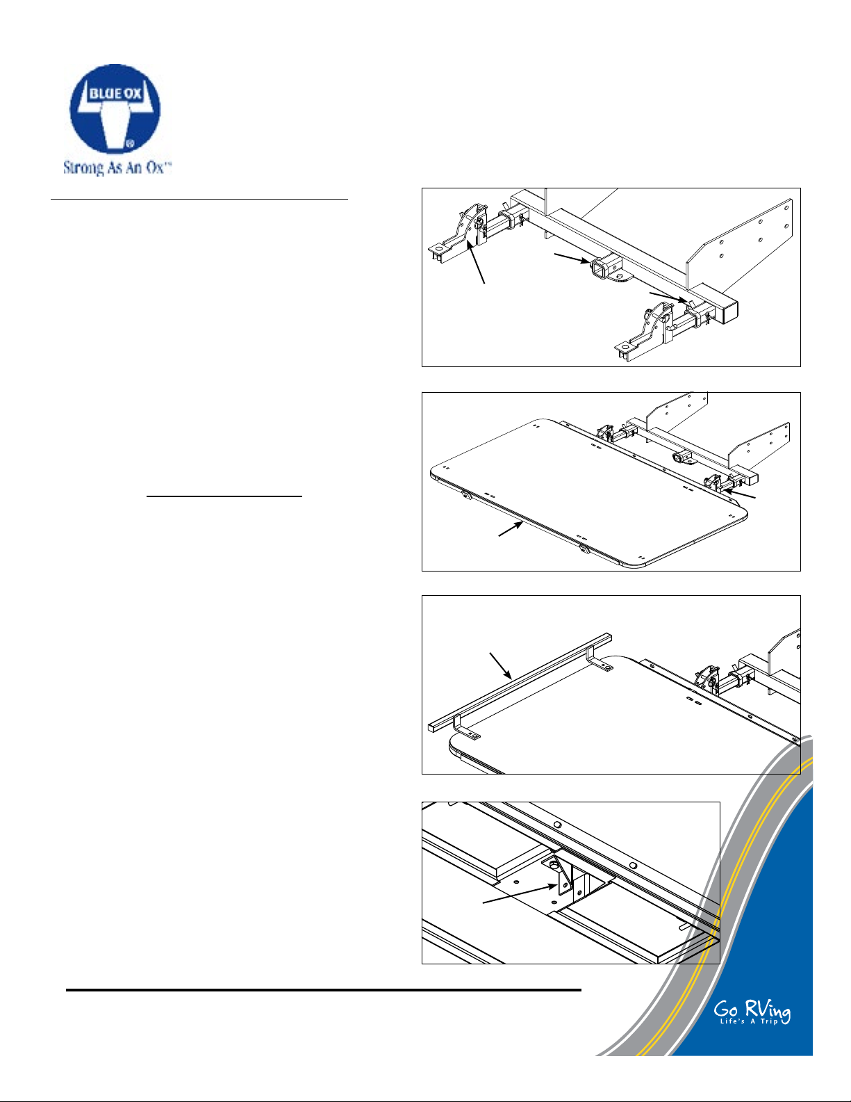
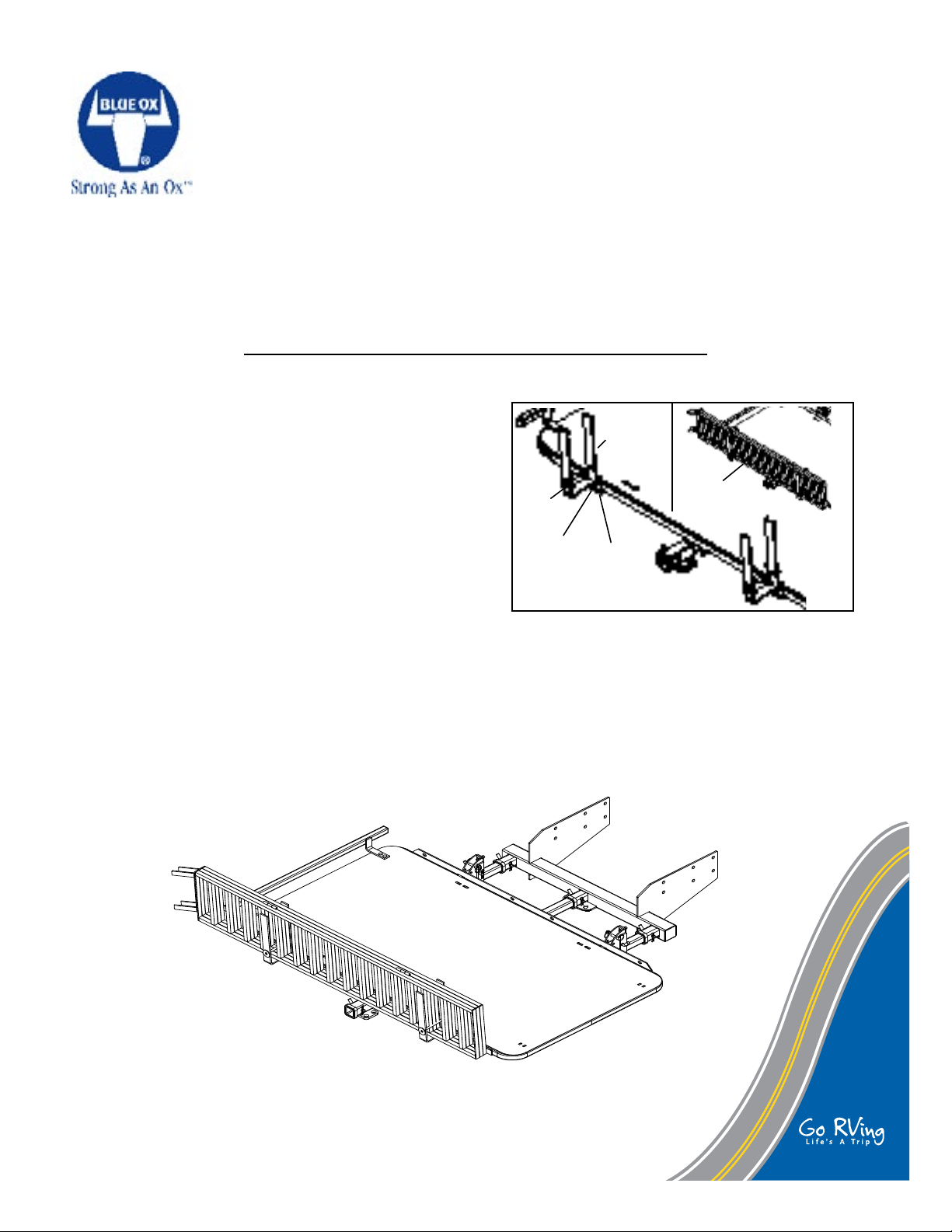
3-Receiver
Deck Support
Assembly
Hitch
5/8" x 3
Hitch Pin
- The original hitch of the coach needs to be replaced
Fig. C
with the SC9000 or a fabricated 3 receiver hitch. With
the two outside receivers having a 43 inch center to
center spacing
SportCarrier I Capacities
LIFTING CAPACITY - ......................... 1000 LBS.
FLAT-TOWING CAPACITY - ............... 5000 LBS.
CARGO HAULING LENGTH - .. 102 INCHES OR
LESS
Deck
Fig. D
Tire Stop
(Installed)
INSTALLING THE CARRIER
1. Pin and clip the two deck support assemblies into
the 3 receiver hitch with 5/8" x 3" eff. hitch pins
(Fig. C).
2. Pin and clip the deck weldment to the deck support assemblies with two 5/8" x 4" hitch pins (Fig.
D). This procedure will take two to three people to
complete.
3. Bolt the tire stop to either side of the deck with four
3/8-16 x 1 1/4" carriage head bolts, two washer
ats, lockwashers, and hex nuts (Fig.E).
4. Bolt the hold up bracket for the center extension
to the back two holes with two 1/2-13 x 1 1/4" hex
bolts and lockwashers (Fig. F).
© 2011 Blue Ox Division, Automatic Equipment Mfg. Co. • One Mill Road, Industrial Park • Pender,
Nebraska 68047 • Phone 402-385-3051 • Fax 402-385-3360 • www.blueox.com
Page 3 of 14 292-2710 Rev A 10/21/11
Hold up
bracket
Fig. F
Fig. E
5/8" x 4
Hitch Pin
Page 5
TM
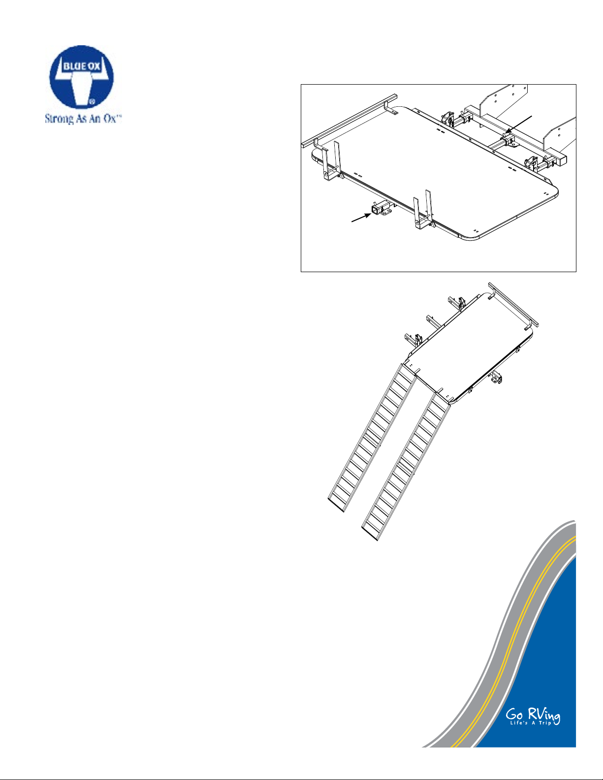
5. Pin the center extension into the center of the 3 re-
CHECK
FINISH
DRN APPD
DEPT
SZ
+
-
-
+
Pender, Nebraska
FRAC. DEC. ANG.
DIM.TOL. UNLESS SPECIFIED
DRN DATE
1
32
+
-
X.XX
X.XXX
SCALE
1
0.030
0.010
2
+
-
C
H
K
D
R
N
D
A
T
E
R
E
V
I
S
I
O
N
A
D
W
G
N
A
M
E
:
E
C
R
E
F
B
C
D
F
I
G
H
FIGH
ALD
A
2/16/2005
R
E
L
E
A
S
E
T
O
P
R
O
D
U
C
T
I
O
N
A
L
D
X:X
XXXXXX
X
X
X
X
ceiver hitch with a 5/8" x 3" hitch pin making sure to
slide the extension into the hold up bracket. Using one
1/2" x 2 5/8" pin (Item 12) and one clip assembly (Item
13), pin the center extension into the hold up bracket
(Fig. G).
LOADING INSTRUCTIONS
Slowly ride the motorcycle or golf cart up the ramps
making sure the tires are centered on the ramps.
Acceleration must be slow and steady, NEVER over
accelerate!
Secure the cargo with as many tie down straps as
needed. Usually four tie down straps are sufcient.
Blue Ox recommends using back tire stops for motor-
cycles, so the tire does not slide side to side.
5/8 x 3
Hitch Pin
Center
Extension
Fig. G
IMPORTANT NOTES:
- If loading a motorcycle onto the deck, Blue Ox
has a black powder coated wheel chock available
(SC9001) for supporting the front tire.
UNLOADING INSTRUCTIONS
To unload, be sure ramps are centered and fastened
in place. Then slowly back down using the brake as
necessary to control the speed.
SAFETY NOTES
Be aware that the deck of the carrier rotates up and
can be pinned in that position. Never stand in the
path of the deck. The deck is heavy and could cause
injury. Be sure both pins are used before letting go of
the deck. Use two people if necessary to lower and
lift the deck.
Insure that hands and feet are away from where the
deck pivots when lowering the deck of SportCarrier I.
Wiping SportCarrier I™ down periodically
will help prevent dust and dirt from building up.
MAINTENANCE
© 2011 Blue Ox Division, Automatic Equipment Mfg. Co. • One Mill Road, Industrial Park • Pender,
Nebraska 68047 • Phone 402-385-3051 • Fax 402-385-3360 • www.blueox.com
Page 4 of 14 292-2710 Rev A 10/21/11
Page 6

TM
FLAT-TOWING WITH SPORTCARRIER I™
WARNING!! - SportCarrier I is designed for FLAT-TOWING vehicles behind it. Towing trailers or boats will increase the
down force thus exceeding the weight carrying capacity of SportCarrier I. Exceeding the capacity WILL lead to damage
and possible product failure.
-SPORTCARRIER I CAN FLAT-TOW A VEHICLE BEHIND IT THAT WEIGHS NO MORE THAN 5000 LBS!
- WHEN FLAT TOWING, BLUE OX STRONGLY RECOMMENDS USING A BRAKE SYSTEM ON THE TOWED VEHICLE.
4 INCH
MAX.
+/- 4"
from level
RECEIVER TUBE
OF COACH
Fig. H
1. Once the cargo is loaded and strapped down securely,
the towed vehicle is now ready to be hooked up.
2. Slide and pin the tow bar to the receiver of SportCarrier
I. Hook up the towed vehicle to the tow bar, making sure
the legs are locked into place. Make sure the tow bar is
no more than +/- 4 inches from being level (Fig. H).
3. Attach one set of safety cables from the RV to the
convenience link on the receiver extension. Then attach another set of safety cables from the convenience
links of the receiver extension to the convenience links
of the towed vehicle. SportCarrier I is now ready for
towing.
4. When the cargo is unloaded from SportCarrier I, the
deck can be pinned in the up position out of the way.
Pin both deck supports with 1/2" x 2 5/8" pins and
clips.
© 2011 Blue Ox Division, Automatic Equipment Mfg. Co. • One Mill Road, Industrial Park • Pender,
Nebraska 68047 • Phone 402-385-3051 • Fax 402-385-3360 • www.blueox.com
Page 5 of 14 292-2710 Rev A 10/21/11
Page 7

TM
Optional Accessories Installation Information
SC9000
Parts List
Ref. No. Qty. Part No. Description
1 1 61-5864 ................................................................................Wldm't, Hitch, Lift
2 2 101-6449 ..................................................................Mounting Plate, Hitch Lift
3 3 200-1483 .......................................................................Pin, 5/8 x 3 Eff. w/Clip
4 12 201-0286 ...................................................5/8-11x1 3/4 Hex Bolt, GRD. 5, ZP
5 12 203-0013 ........................................................................ 5/8 Lock Washer, ZP
6 12 202-0008 ........................................................................... 5/8-11 Hex Nut, ZP
IMPORTANT: Use only genuine factory replacement parts on your SportCarrier I™. Do
not substitute homemade or nontypical parts. If parts are lost or in need of replacement,
for your safety and the preservation of your SportCarrier I, order replacement parts
through your nearest Blue Ox dealer or distributor.
© 2011 Blue Ox Division, Automatic Equipment Mfg. Co. • One Mill Road, Industrial Park • Pender,
Nebraska 68047 • Phone 402-385-3051 • Fax 402-385-3360 • www.blueox.com
Page 6 of 14 292-2710 Rev A 10/21/11
Page 8

TM
Optional Accessories Installation Information
SC9000
INSTALLATION:
Be sure to use the "Lift and Carrier Compatibility Information" to estimate the amount of weight that will be applied
to the rear axle BEFORE INSTALLATION!! Never exceed the weight rating of the rear axle or tire load ratings.
Doing so will cause dangerous driving conditions, and possible damage to the towing vehicle!
The mount plates should be mounted directly to the main C-Channels of the RV chassis for the most support.
Installation of the receiver requires fabrication of mount plates and welding the mount plates to the 3 receiver
weldment. Have a qualied hitch shop install receiver.
Installation of optional SC9000 receiver requires fabrication of mount plates (3/8" to 1/2" thick depending on
application) and welding the mount plates to the 3 receiver hitch.
Installers be aware of the rear exhaust of the RV when designing the mount plates, so the carrier clears the
exhaust when pinned into receiver.
The hitch receiver needs to be welded by a certied welder.
1. NOTE 1: If original hitch has motor mounts incorporated into it, don't touch original hitch, the mount plates will have to
go around it.
NOTE 2: The original hitch of the coach needs to be replaced with the SC9000 or a fabricated 3 receiver hitch. With
the two outside receivers having a 43 inch center to center spacing (Fig. A). Once the original hitch is removed,
measure between the two c-channels of the frame of the coach. This measurement is what the distance between the
mounting plates need to be (Fig. A). The hitch receiver needs to be positioned so when the deck is ipped up and
pinned, the deck will not hit the coach bumper or berglass body (Fig. B). The recommended height of the receivers
is 18-20 inches from the ground to the center of the receivers. There should be at least 6 holes in each mount plate
for the 3/4-10 x 1 3/4" hex bolts. Once mount plates are welded to the 3 receiver hitch, bolt the hitch receiver assembly to the c-channels of the coach with 3/4-10 x 1 3/4" hex bolts, lockwashers, and hex nuts (included with SC9000).
COACH
Fig. A
© 2011 Blue Ox Division, Automatic Equipment Mfg. Co. • One Mill Road, Industrial Park • Pender,
Nebraska 68047 • Phone 402-385-3051 • Fax 402-385-3360 • www.blueox.com
Page 7 of 14 292-2710 Rev A 10/21/11
Fig. B
Page 9

TM
Optional Accessories Installation Information
SC9023
Parts List
Qty. Part No. Description
1 229-0684 ............................................................................ Ramps, Aluminum
2 229-0715 ................................................................................Strap, Tie Down
IMPORTANT: Use only genuine factory replacement parts on your SportCarrier I™. Do
not substitute homemade or nontypical parts. If parts are lost or in need of replacement,
for your safety and the preservation of your SportCarrier I, order replacement parts through
your nearest Blue Ox dealer or distributor.
© 2011 Blue Ox Division, Automatic Equipment Mfg. Co. • One Mill Road, Industrial Park • Pender,
Nebraska 68047 • Phone 402-385-3051 • Fax 402-385-3360 • www.blueox.com
Page 8 of 14 292-2710 Rev A 10/21/11
Page 10

TM
Optional Accessories Installation Information
SC9023
The SC9023 ramps are designed to be used with Blue Ox® SportCarriers I™ and II™ (SC2100 and SC2101). Each
aluminum ramp has a 750 lb. capacity, giving the set of ramps the ability to handle up to 1,500 pounds. The SC9023
ramp kit can easily be stored with the addition of the SC9009 ramp bracket kit.
SC9023 INSTALLATION INSTRUCTIONS
1. Place the ramp tabs on the deck of the carrier on the
opposite end of the tire stop.
2. Secure the ramps using the included tie down straps.
Fasten one end of the strap to a ramp cross bar and
the other end to the slot on the edge of the deck near
the ramps. Do this to both ramps.
© 2011 Blue Ox Division, Automatic Equipment Mfg. Co. • One Mill Road, Industrial Park • Pender,
Nebraska 68047 • Phone 402-385-3051 • Fax 402-385-3360 • www.blueox.com
Page 9 of 14 292-2710 Rev A 10/21/11
Page 11

TM
Optional Accessories Installation Information
SC9009
Parts List
Ref. No. Qty. Part No. Description
1 2 61-6118 ...................................................................Weldment, Bracket, Ramp
2 2 299-0373 ................................................... Weldment, Pin Cycle Rack, ZP CL
3 2 62-3458 ..........................................................Assy, Hair Pin Clip, Cycle Rack
4 2 201-0278 ........................................................... 3/8-16 x 3/4" Sq Hd Cap Knrl
4 290-0446 ...............................................Cover, Protective Plastic (not shown)
3
1
2
4
IMPORTANT: Use only genuine factory replacement parts on your SportCarrier I™. Do
not substitute homemade or nontypical parts. If parts are lost or in need of replacement,
for your safety and the preservation of your SportCarrier I, order replacement parts through
your nearest Blue Ox dealer or distributor.
© 2011 Blue Ox Division, Automatic Equipment Mfg. Co. • One Mill Road, Industrial Park • Pender,
Nebraska 68047 • Phone 402-385-3051 • Fax 402-385-3360 • www.blueox.com
Page 10 of 14 292-2710 Rev A 10/21/11
Page 12
TM
Optional Accessories Installation Information
FINISH
DEPT
SZ
+
-
-
+
Pender, Nebraska
FRAC. DEC. ANG.
DIM.TOL. UNLESS SPECIFIED
DRN DATE
1
32
+
-
X.XX
X.XXX
SCALE
1
0.030
0.010
2
+
-
C
H
K
D
R
N
D
A
T
E
R
E
V
I
S
I
O
N
A
D
W
G
N
A
M
E
:
E
C
R
E
F
B
C
D
F
I
G
H
-
2
FIGH-2
2/23/2005
R
E
L
E
A
S
E
T
O
P
R
O
D
U
C
T
I
O
N
A
L
D
X:X
X
X
X
X
SC9009
The SC9009 Ramp Bracket kit is designed for use with Blue Ox® SportCarriers I™ (SC2100) and II™ (SC2101). The
SportCarrier must be assembled and installed per its instructions before the ramp bracket kit installation can begin.
SC9009 INSTALLATION INSTRUCTIONS
1. Slide ramp brackets into the channels on the rear of the
deck.
2. Insert the 3/8-16 x 3/4" square head cap knurl set
screw into the channel. Using the 12" crescent wrench,
securely tighten the screw. Do this to both ramp brackets.
STORING THE RAMPS
1. Slide the unfolded ramp into the ramp bracket.
2. Insert the cycle rack pin into the ramp bracket.
3. Insert the hair pin clip through the rack pin. Do this to
both ramp brackets.
NOTE: Ramp brackets can be taken off the back of the
deck and placed on the underside of the deck when in
the UP position.
© 2011 Blue Ox Division, Automatic Equipment Mfg. Co. • One Mill Road, Industrial Park • Pender,
Nebraska 68047 • Phone 402-385-3051 • Fax 402-385-3360 • www.blueox.com
Page 11 of 14 292-2710 Rev A 10/21/11
Page 13

TM
SC2100 With all Optional Accessories Installed
SC2100
IMPORTANT: Use only genuine factory replacement parts on your SportCarrier I™. Do
not substitute homemade or nontypical parts. If parts are lost or in need of replacement,
for your safety and the preservation of your SportCarrier I, order replacement parts through
your nearest Blue Ox dealer or distributor.
© 2011 Blue Ox Division, Automatic Equipment Mfg. Co. • One Mill Road, Industrial Park • Pender,
Nebraska 68047 • Phone 402-385-3051 • Fax 402-385-3360 • www.blueox.com
Page 12 of 14 292-2710 Rev A 10/21/11
Page 14

TM
SC2100 With all Optional Accessories Installed
SC2100
Parts List
Ref. No. Qty. Part No. Description
1 1 61-6080 ..........................................................Wldm't, Deck, SC2100/SC2101
2 2 61-6073 .........................................................................Wldm't, Deck Support
3 2 61-6118 ........................................................................Wldm't, Bracket, Ramp
4 1 61-6077 .......................................Wldm't, Hold Up Bracket, Center Extension
5 1 61-6048 ................................................................... Wldm't, Center Extension
6 1 61-6092 ................................................................................ Wldm't, Tire Stop
7 2 299-0373 ................................................................................. Wldm't, Pin, ZP
8 1 SC9000 ..................................................................................... Receiver Hitch
9 1 229-0684 ................................................................................. Ramp, 1500 lb.
10 2 200-1701 ...............................................................Pin, 5/8" x 4" eff. w/clip, ZP
11 4 200-1483 ...............................................................Pin, 5/8" x 3" eff. w/clip, ZP
12 3 229-0520 ..................................................................Pin, 1/2" x 2 5/8" eff. , ZP
13 3 84-0001 ............................................................................Quick Pin Assembly
14 2 62-3458 ............................................................................. Assy, Hair Pin Clip,
15 2 61-6135 ....................................................................Wldm't,Adjuster, SC2100
16 2 201-0323 ........................... 1/2-13 X 1 3/4" Square Head Cap Knrl Set Screw
17 2 201-0011 ..........................................1/2-13 x 1 1/4" Hex Head Bolt, Grd.5, ZP
18 4 201-0008 ................................. 3/8-16 x 1 1/4" Carriage Head Bolt, Grd.5, ZP
19 4 201-0278 ...............................3/8-16 x 3/4" Square Head Cap Knrl, Grd.5, ZP
20 2 202-0073 ...................................................... 5/8-11 Hex Flange Whiz Nut, ZP
21 2 202-0072 ......................................................1/2-13 Hex Flange Whiz Nut, ZP
22 4 202-0003 ...........................................................................3/8-16 Hex Nut, ZP
23 2 203-0012 .........................................................................1/2" Lockwasher, ZP
24 4 203-0010 .......................................................................... 3/8 Lockwasher, ZP
25 2 102-6593 .....................................................................................Flat, Tirestop
© 2011 Blue Ox Division, Automatic Equipment Mfg. Co. • One Mill Road, Industrial Park • Pender,
Nebraska 68047 • Phone 402-385-3051 • Fax 402-385-3360 • www.blueox.com
Page 13 of 14 292-2710 Rev A 10/21/11
Page 15

TM
SPORTCARRIER I
ONE YEAR WARRANTY
Automatic Equipment Manufacturing Co. ("Automatic") warrants to the rst retail purchaser
that each item of equipment manufactured by Automatic shall be free from defect in material and
workmanship under normal use and service for one year.
Automatic will repair or replace any parts which (a) shall be returned to an authorized dealer,
distributor, or the factory, with transportation charges prepaid, and (b) after examination by Automatic, are found to be defective. This warranty will not cover, in any way, any alleged damages
caused by incorrect or improper installation, improper use, modication or neglect of product,
or failure of the user to follow the guidelines contained in the instructional material provided by
Automatic.
REPAIR OR REPLACEMENT AS SET FORTH IN THIS WARRANTY IS THE SOLE EXCLUSIVE REMEDY OF THE PURCHASER. AUTOMATIC SHALL NOT BE LIABLE FOR
ANY INCIDENTAL OR CONSEQUENTIAL DAMAGES FOR BREACH OF ANY EXPRESS
OR IMPLIED WARRANTY ON THIS PRODUCT. EXCEPT TO THE EXTENT PROHIBITED
BY APPLICABLE LAW, ANY IMPLIED WARRANTY OF MERCHANTABILITY OR FITNESS FOR A PARTICULAR PURPOSE ON THIS PRODUCT IS LIMITED IN DURATION TO
THE DURATION OF THIS WARRANTY.
Some states do not allow the exclusion or limitation of incidental or consequential damages,
or allow limitations on how long an implied warranty lasts, so the above limitations or exclusions
may not apply to you. This warranty gives you specic legal rights and you may also have other
rights which vary from state to state.
Automatic reserves the right to make changes or add improvements to its products at any time
without incurring any obligation to make such changes to previously manufactured equipment.
No liability is assumed for bodily injury that may be inicted on the operator, spectator or
general public who might be in the general area while this equipment is in use.
IMPORTANT: Coverage and performance under the foregoing warranty is conditioned upon
the rst retail purchaser completing and returning the customer registration card to Automatic
within ten days of delivery date and upon the original serial number being visible on the product
and unaltered. Automatic will not honor any warranty claims unless the warranty registration
card is on le at Automatic's factory in Pender, Nebraska.
Automatic Equipment Manufacturing Co.
P.O. Box P, Pender, NE 68047
2/05
© 2011 Blue Ox Division, Automatic Equipment Mfg. Co. • One Mill Road, Industrial Park • Pender,
Nebraska 68047 • Phone 402-385-3051 • Fax 402-385-3360 • www.blueox.com
Page 14 of 14 292-2710 Rev A 10/21/11
Page 16

TM
TO BE VALID, THE WARRANTY CARD MUST BE
COMPLETED IN ITS ENTIRETY BY AN AUTHORIZED
DISTRIBUTOR OR DEALER AND SENT TO AUTOMATIC
EQUIPMENT MFG. CO., PENDER, NEBRASKA. FAILURE
TO DO SO WILL VOID THE WARRANTY.
Repair parts may be ordered through your nearest
Automatic dealer or distributor.
SERIAL NUMBER -
Product Safety Policy Statement
It is, and shall continue to be, a primary objective of Automatic Equipment Manufacturing Company to provide customers with safe and reliable products. Automatic will, and has,
established safety procedures in product design, manufacture, promotion and sales; and will
coordinate efforts to promote customer safety to the greatest extent possible. Each department
has primary responsibility for the promotion of safety under the guidelines of the Product Safety
SC2100
SportCarrier I™
© 2011 Blue Ox Division, Automatic Equipment Mfg. Co. • One Mill Road, Industrial Park • Pender,
Nebraska 68047 • Phone 402-385-3051 • Fax 402-385-3360 • www.blueox.com
 Loading...