

Page 1
BX8893
AutoStop™
Operator Manual &
Installation Instructions
Serial Number
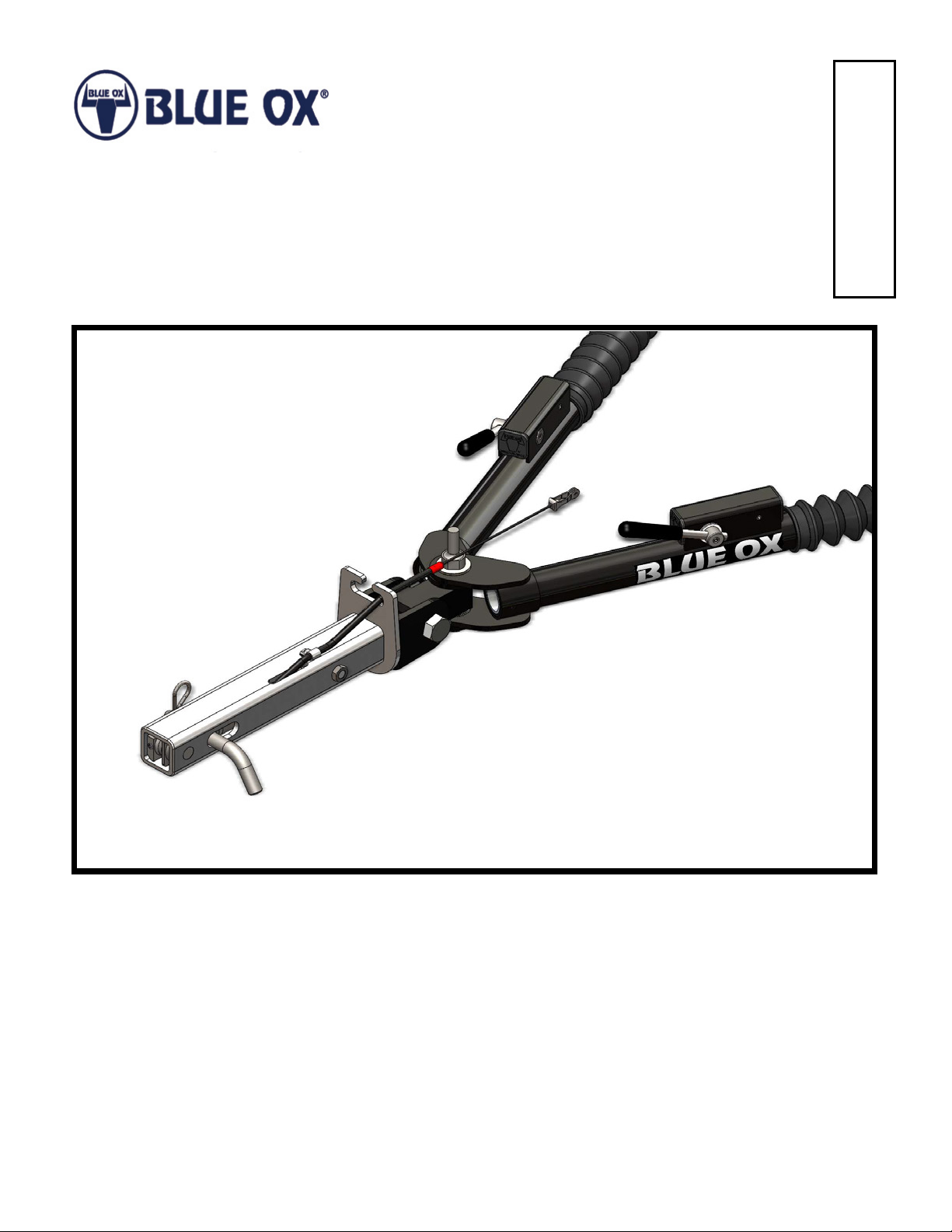
AutoStop™ Hitch Connector
Alpha & Aladdin Tow Bars
(7500 lb) 2” Receiver
292-2214 Rev A Page 1 of 12 10/4/13
Page 2
BX8893
AutoStop™
Operation Manual & Installation Instructions
AutoStop™ uses the forward momentum of your towed vehicle to effect a smooth quick stop,
reducing braking distances as much as 30 percent. When your RV slows down, the momentum of
the towed vehicle pushes AutoStop™ into the hitch. AutoStop™ retracts the cable, proportionally
activating your car’s brakes. The more force applied to AutoStop™, the tighter the cable - for even
more supplemental braking power. The AutoStop™ cable wraps around your car’s brake pedal
arm and connects to the receiver hitch. You determine when the car’s brakes will activate by
adjusting the preload compression of the power spring. AutoStop™ does not invade the car’s or
motorhome’s brake system in any way. The adjustable preload and power return is easily modied
but still proportional in braking.
CAUTION: The loaded vehicle weight must not exceed
the weight of any of your towing accessories such as: the tow
bar, safety cables, pins or the AutoStop™.
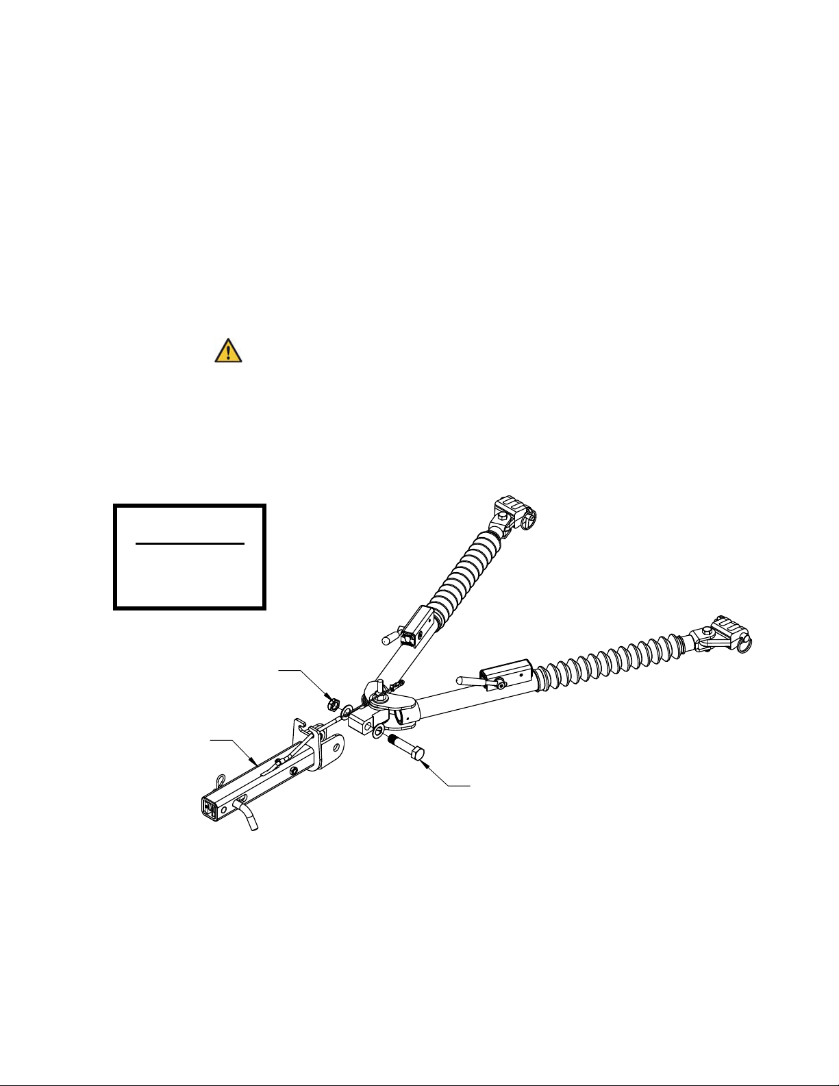
AutoStop™ Tow Bar Installation
Tools Required
1-1/8” Socket
1-1/8” Wrench
Existing 3/4"-16 Nut
AutoStop
Hitch Connector
Existing 3/4"-16 Bolt
1. Using a 1-1/8” socket and wrench, remove the existing hitch connector from the tow bar.
2. Install the AutoStop™ Hitch Connector onto the tow bar using the existing plastic washers and
3/4” hardware.
292-2214 Rev A Page 2 of 12 10/4/13
Page 3
BX8893
AutoStop™
Operation Manual & Installation Instructions
AutoStop™ Cable Attachment
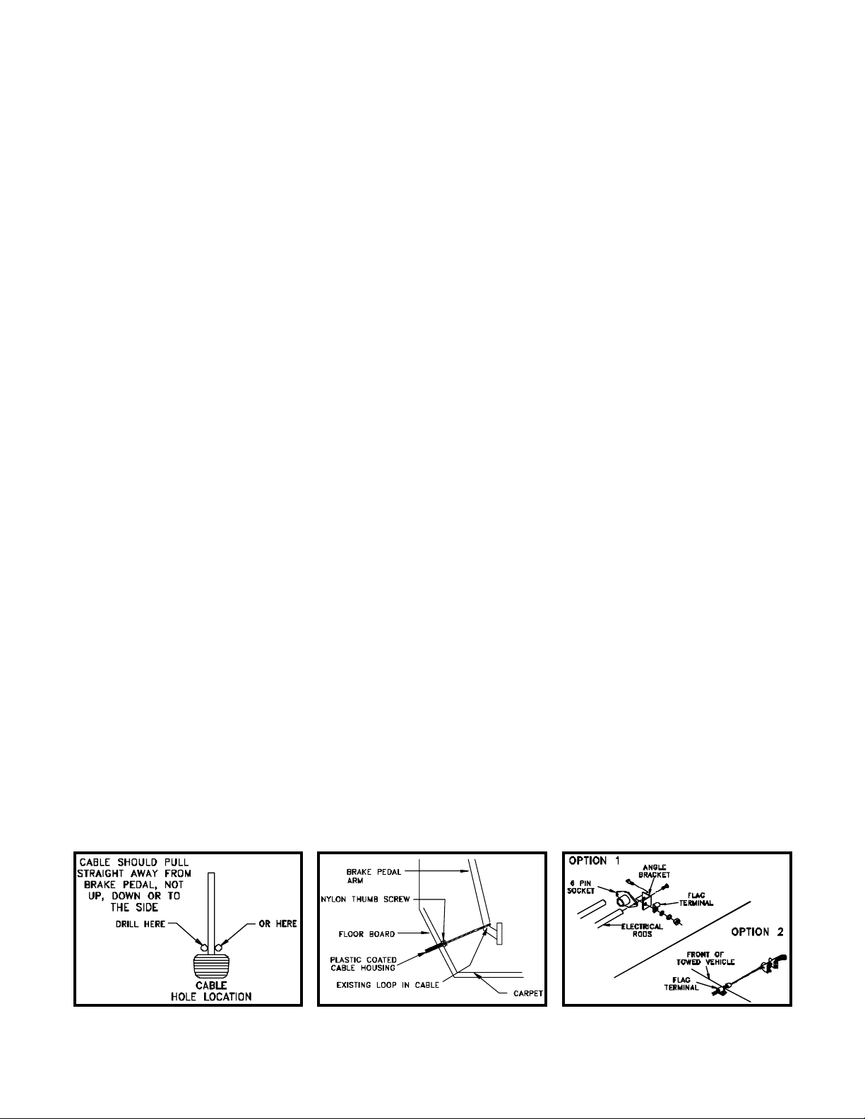
1. From the drivers seat note the distance and direction from the steering column to the brake pedal
when the brake pedal is fully depressed. This will normally be a little below and a little inboard of
the steering column. Mark the spot on the carpet with chalk where the cable should pass through
the oor. Measure the distance and direction and conrm that a drilled hole will not interfere with
anything fastened or close to the drilled hole. When selecting the location for the hole, it should be
positioned so the cable is pulling straight back on the brake pedal arm, not to either side and not
up or down. (Figure 3 & 4)
2. After you have conrmed that the location for the hole will not cause any problems, pull the carpet
back and drill a 1/8 inch pilot hole. Allow the drill bit to just barely break through the metal oor.
Next, inspect where the hole actually is from the engine compartment side to verify that this location will not cause problems and to see how the cable aligns with the brake arm. If the hole needs
to be relocated, redrill and seal the previous hole with a rivet or sealant. When alignment is correct, enlarge the pilot hole with a 5/16 inch bit. Cut a slit in the carpet to correspond to the hole in
the oor.
3. Now you are ready to install the coated brake cable housing in the towed vehicle. Pull the inside
cable from the housing and set aside. The cable should run through the hole drilled in the oor
board into the engine compartment. Visually select a route that will not interfere with any moving
components or possibly contact electrical terminals. Route the cable to the central area (preferably through the opening where the attachment tabs extend through) of the front plastic facia. The
cable housing should be fastened in the engine compartment (on frame) with ag type terminals
provided in parts bag. Fasten the end of the plastic housing to the baseplate with the supplied
angle bracket. Figure 5 NOTE: Flag terminals are used so the cable housing is stationary allowing
the inside cable to move freely. When installed properly, the nylon thumb screw should be showing
on top of the carpet. Avoid abrupt bends in the cable housing as this will cause friction and premature wear of the cable. The cable housing should protrude a 1/2” beyond the bumper, or bumper
skirt or where ever the ag terminal is mounted, pointing directly at the hitch ball. Figure 5
4. Lubricate the cable with silicon spray and feed the cable back through the front end of the cable
housing into the passengers compartment. Loop the cable around the brake pedal arm allowing
the cable to feed directly and straight into the cable housing. If alignment is proper, the cable will
feed into the cable housing when the brake pedal is depressed. See Figure 4. Leave 1/2” of cable
housing extending from the ag terminal on the front of the vehicle. See Figure 5.
Figure 4
Figure 5Figure 3
continued to next page
292-2214 Rev A Page 3 of 12 10/4/13
Page 4
BX8893
AutoStop™
Operation Manual & Installation Instructions
continued to previous page
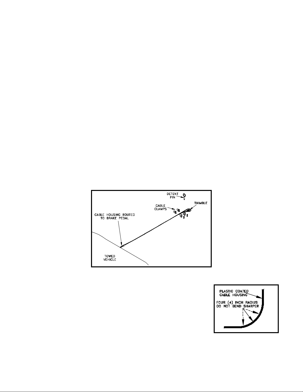
7. Hook the connector cable assembly to the cable fork on the AutoStop™ receiver cable assembly.
Attach the cable thimble to the other end of the connector cable assembly with the detent pin.
(Figure 6) Run the loose end of the brake cable through the fork and thimble, double it back on
itself and secure it with the two cable clamps. Place the rst clamp as close as possible to the
thimble and the second cable clamp about four (4) inches from the rst. Before tightening the
clamps adjust the cable length so there is about four (4) inches of vertical play in the cable before
the towed vehicle’s braking lights come on.
8. Cut off and discard any excess cable. Recheck this adjustment after a trial run. If the towed
vehicle’s brake lights come on at the slightest touch of the cable, with the cable properly adjusted,
the brake lights are coming on during pedal free travel. Most brake light switches are not
adjustable, so install a bungee cord from the pedal to the driver’s seat base to reduce the free
travel movement of the pedal while towing.
9. Install all other safety and towing equipment as required. The AutoStop™ only actuates the towed
vehicles brakes. It does not eliminate the necessity of safety chains, towing lights, transmission
pumps or driveshaft disconnects.
Figure 6
MECHANICAL INSTALLATION NOTES
When routing the housing, do not make a turn tighter than a four (4) inch
radius (Figure 7). Anchor the housing in the middle of the bend. There
are plastic cable ties and extra ag terminals included with the kit. You
will also need to anchor the housing as close as possible to the end that
sticks out of the grill of the car. After you have the housing installed and
the cable inserted, lay under the vehicle and have someone pull on the
cable. When pressure is applied to the cable the housing will tend to try
to “straighten out” through the bends. If there are several places where
this happens, most of the cable pull will be used up straightening the housing rather than pulling on
the brake pedal. Note where the housing is trying to straighten and anchor these areas.
292-2214 Rev A Page 4 of 12 10/4/13
Figure 7
Page 5

BX8893
AutoStop™
Operation Manual & Installation Instructions
AutoStop™ Electrical Installation
The AutoStop™ uses the towed vehicles brakes. Most vehicle’s brake lights work with the key in
the off or in the accessory position. This creates the possibility of the towed vehicle’s battery being
drained while towing as the brake lights are activated each time the brake pedal is depressed by the
AutoStop™. Included are electrical parts which bypass the towed vehicles battery while towing. The
only change you will notice to the towed vehicle is that the brake lights will only be activated by the
brake pedal when the ignition is in the “on” position. We also include a light indicator that is installed
in the dash of the towing vehicle which lights up when the brake pedal in the towed vehicle is pulled
on by the AutoStop™. (Figure 8)
1. Locate the brake light switch which is activated when the brake pedal is pressed down. Locate the
hot wire into the switch and the wire from the switch to the brake lights. You will need to splice into
the wire coming from the switch to the brake lights. Cut the wire at a convenient place and strip
the two ends.
2. If there is room, you can locate the relay where you cut the wires. If there isn’t room, splice wires
onto the ones you cut to give yourself working room. Black wire and butt connectors are supplied
in the parts sack.
3. Strip one end of the yellow wire and twist it together with the wire coming from the brake switch.
Crimp a female spade terminal on the twisted pair. Slide the terminal over the male terminal on the
relay labeled “87”.
4. Crimp a female spade terminal on the end of the wire going to the brake lights. Slide this terminal
over the male terminal on the relay labeled “30”.
5. Locate a bolt to use as a ground. Cut a piece of the black wire long enough to reach from the
relay to the bolt. Strip both ends of the black wire and crimp a ring terminal on one end and a
female spade terminal on the other. Put the ring terminal under the head of the bolt and the spade
terminal on the male terminal on the relay labeled “85”.
6. In the car’s fuse panel locate a fuse that is “hot” only when the ignition switch is in “on” position.
Use the mini fuse tapper with fuse, crimp a female spade terminal on the end of black wire and
attach it to fuse tapper. Cut a piece of black wire to reach from the fuse to the terminal on the relay
labeled “86”.
7. Route the yellow wire from the relay through the engine compartment of the car into the wiring
disconnect plug. Then from the wiring disconnect plug on the back of the coach along the bottom
of the coach and into the dash of the coach. Tie the wire to the frame of the coach with cable ties
or other suitable means.
8. Locate a suitable place in the dash and drill a half (1/2) inch hole for the light indicator. Crimp a
butt connector to both wires and insert the indicator into the dash.
9. Cut the yellow wire to length and attach it to one of the wires on the indicator. Locate a bolt to use
as a ground. Cut a piece of black wire to length and connect it to the other indicator wire, crimp a
ring terminal on the other end of the black wire and fasten it to the grounding bolt.
continued to next page
292-2214 Rev A Page 5 of 12 10/4/13
Page 6

BX8893
AutoStop™
Operation Manual & Installation Instructions
continued to previous page
10. Gather up the wires and the relay. Anchor them up out of the way so they will not interfere with
driving the vehicle with wire ties.
Figure 8
WARNING: Motorhome dash light must be installed according to installation instructions or warranty
will be void.
RV DASH LIGHT
1. Dash light will allow a visual indication that the towed vehicles' brakes are activated.
2. Should light remain "ON" after braking, corrective action must be taken. "STOP" the RV to
investigate. You may be experiencing a malfunction of the system, which would require you to
check, the braking system for proper operation.
a. Cable tension should comply with the installation instructions.
b. Check wiring of relay in towed vehicle to insure proper installation.
c. If breakaway device is installed, refer to its installation instructions.
3. Should dash light activate while turning, corrective action must be taken. “STOP” the RV to
investigate.
a. If readjustment of cable is needed, this is usually an indication that the cable is too tight or
. is hanging up on one of the towing components.
TESTING
The electrical installation can be tested to see if it is installed correctly. When applying the brakes
with the key in the off and the accessory position, the rear brake lights should not come on, but when
applying the brakes with the key in the on position, the brake lights should come on.
292-2214 Rev A Page 6 of 12 10/4/13
Page 7

BX8893
AutoStop™
Operation Manual & Installation Instructions
AutoStop™ Maintenance
The AutoStop™ and the inside of the receiver tube should be cleaned and lubricated with silicon
spray at 1,000 mile intervals to prevent the buildup of road dust preventing the action to slide with
ease. The AutoStop™ should be disassembled, thoroughly cleaned and lubricated every 10,000
miles. At this time the actuating cable should be replaced if there are any signs of cable wear.
DISASSEMBLY INSTRUCTIONS
If your AutoStop™ becomes sluggish or you are in need of replacing a broken part, the following
disassembly instructions will step you through how to dismantle, clean and reassemble your
AutoStop™.
1. Remove the AutoStop™ from the receiver hitch. Remove the hex bolt. (Figure 9)
2. Loosen the set screw in the cable anchor and remove the 5/8" rod going through the AutoStop™
tube. NOTE: You may need to tap out the 5/8" rod with a punch.
3. At this point, slide the pulleys and adjusting bolt assembly out of the AutoStop™ tube. NOTE: Use
caution when removing the pulleys. The cable is coiled around the pulleys several times and may
unwind when removed from of tube. This is normal, reassembly will be explained in a later section.
4. Remove the round head screw holding the cable clamp, then pull the cable assembly out of the
AutoStop™ tube.
5. Clean all parts with a mild solvent such as WD-40 and be sure to dry all parts. Use a brush to
insure the inside of the AutoStop™ tube is clean as well.
Figure 9
292-2214 Rev A Page 7 of 12 10/4/13
Page 8

BX8893
AutoStop™
Operation Manual & Installation Instructions
ASSEMBLY INSTRUCTIONS
1. Slide the cable assembly back into the slotted hole in the AutoStop™ tube and secure the
cable clamp with the ag terminal and the round head screw. Be sure the plastic cable housing
is inserted in the slot so the inside cable does not rub at the slot, but also be sure the cable
assembly isn't inserted too far that it interferes with the spring inside the tubing. See Figure 10.
2. Lay the AutoStop™ tube on a table or bench with the hitch mount end towards you. (Figure
11) Thread the adjusting nut onto the adjusting bolt all the way on the threads. Slide the
compression spring onto the adjusting bolt all the way onto the adjusting nut. Then place the end
tting on the other end of spring. Slide this assembly into the AutoStop™ tube until adjusting bolt
hole is lined up with the two front holes of AutoStop™ tube, then insert the 7/16" hex bolt through
the AutoStop™ tube and secure bolt with hex jam nut.
3. Place one of the two identical pulleys with the beveled edge on the table. Place the long bushing
through this pulley, next place the center spacer with chamfers on the bottom right side. Place on
top of the spacer the other pulley with the beveled edge on top.
4. Set the tube aside and nd the narrow pulley. Please note that the narrow pulley's groove is off
center. Set the pulley on the bench with the groove oriented closest to the bench. (Figure 12&16)
Insert the short bushing into the pulley and the 5/8 rod into the bushing. (Figure 13)
Figure 10
Primary Pulley Assembly
Figure 11
Bottom View of AutoStop™
continued to next page
292-2214 Rev A Page 8 of 12 10/4/13
Page 9

BX8893
AutoStop™
Operation Manual & Installation Instructions
continued from previous page
5. Place the pulley divider on the pulley. (Figure 13) NOTE: The pulley
divider is NOT square. It is slightly wider one direction than the other.
During use, the pulley divider must be oriented long side horizontal, to
keep the cable from jumping between pulleys.
Secondary Pulley Assembly
6. Set the wide pulley on top of the pulley divider. It is symmetrical so it can
be put on either way. (Figure 14) Set the cable anchor on top of the wide
pulley with the groove facing you and the notch out of the corner to your
right. (Figure 15)
7. Set the movable pulley assembly next to the AutoStop™ tube, and next to
it place the stationary pulley assembly. (Figure 16) You are now ready to
route the cable around the pulleys.
8. Pull the cable through so you have all the slack at the back where you will
be wrapping the cable. The AutoStop™ tube should still be positioned
with the tongue at side towards you. (Figure 16)
9. Refer to (Figure 17) while wrapping cable around the pulleys. The cable
should protrude from the AutoStop™ tube at the lower corner of the
tongue at side facing you. From here, route the cable in front of pulley
“A” and counterclockwise around pulley “B”. Continue on the back side
back to pulley “A” and go around it counterclockwise also. From here,
route the cable around pulley “C” counterclockwise then pulley “D”
counterclockwise. Lay the cable in the groove in the cable anchor and set the cable swage into
the notch in the cable anchor.
Figure 12
Figure 13
Figure 14
Figure 15
10. Once you have the cable wrapped properly, pull slowly on the other end of the cable while
holding the pulleys and swage in place with the other hand to prevent the cable from unwrapping.
Keep tension on the cable and slide the pulleys into the AutoStop™ tube. (Figure 18) When the
second set of pulleys start into the tube, stop and remove the 5/8 rod.
11. Pull slowly on the cable until the holes in the second set of pulleys line up with the holes in the
end of the AutoStop™ tube and insert the 5/8 rod.
12. With the AutoStop™ still on its side, be sure that the pulleys, cable anchor, and pulley divider are
all together and pressed down to the side of the tube. Place a 20 thousandths inch (.020”) feeler
gauge between the cable anchor and wide pulley and tighten the set screw in the end of the
cable anchor. (Figure 19) NOTE: Be sure to keep the 5/8 rod centered in the AutoStop™ tube
while tightening the set screw.
continued to next page
292-2214 Rev A Page 9 of 12 10/4/13
Page 10

BX8893
Suggested initial preload ranges are:
AutoStop™
Operation Manual & Installation Instructions
continued from previous page
Figure 16
Bottom View of AutoStop™
Figure 17
Figure 18
Figure 19
AutoStop™ Adjustment
The AutoStop™ "Load Ranger" is equipped with a return spring and an adjusting nut to set the spring
pre-load in proportion to the weight of the towed vehicle. This pre-load will not allow the activation of
the towed vehicle's brakes during light braking of the towing vehicle. This also prevents application
of the towed vehicle's brakes when descending a moderate grade against engine compression, jake
brake or exhaust brake, but still allows proportional braking when the towing vehicle's service brakes
are applied. Before making any adjustment, drive the rig a few blocks and re-check the installation for
proper cable slack. With a at blade screwdriver, rotate the adjusting nut upward with a down motion
of the screwdriver handle to increase the preload. This will move the nut in the direction of the towing
vehicle, compressing the return spring. Continue to rotate the adjusting nut to the desired preload. If
you desire the AutoStop™ to activate only during very heavy braking, adjust to the max. setting. After
your initial setting, adjust to your driving preference if needed. The location of the adjusting nut is
shown in Figure 20. The initial preload ranges are listed below.
1/4" - Towed vehicle under 2,000 lbs.
1/2" - 2,000 to 3,500 lbs.
3/4" - 3,500 to 5,000 lbs.
1" - Maximum preload
Figure 20
292-2214 Rev A Page 10 of 12 10/4/13
Page 11

BX8893
AutoStop™
Operation Manual & Installation Instructions
Replacement Parts
9
15
28
7
8
6
5
2
27
26
12
3
1
4
23
14
21
24
13
10
11
22
18
25
16
17
20
19
Item No. Part No. Description Qty.
1.................................... 61-5129 ................................ Hitch Connector Weldment ....................................................... 1
2.................................... 100-1103 ............................... Yoke Casting .............................................................................1
3.................................... 290-0348 .............................. Plastic Spacer, 7/64” x 13/16” ID x 3” OD ................................. 1
4.................................... 202-0152 .............................. 3/4”-16 Hex Nylon Lock Nut .....................................................1
5.................................... 201-0622 .............................. 3/4”-16 x 2-1/2” Hex Head Bolt, Grade 5, ZP ........................... 1
6.................................... 203-0064 .............................. 3/4” SAE Flat Washer ............................................................... 2
7.................................... Existing ................................. 3/4”-16 x 3-1/4” Bolt & 3/4”-16 Lock Nut ................................... 1
8.................................... Existing ................................. Plastic Spacers, 1/16” x 13/16” ID x 1-1/2” OD ........................3
9.................................... 299-0255 .............................. Adjusting Nut ............................................................................1
10.................................. 299-0256 .............................. Adjusting Bolt ............................................................................1
11 .................................. 299-0289 .............................. Pulley Divider ............................................................................ 1
12.................................. 201-0192 .............................. #10-32 x 1/2” Round Slot Head Screw .....................................1
13.................................. 222-0076 .............................. Compression Spring .................................................................1
14.................................. 201-0366 .............................. 7/16”-20 x 2-1/4” Hex Head Bolt, Grade 5 ................................1
15.................................. 202-0110 ............................... 7/16”-20 Hex Jam Nut ..............................................................1
16.................................. 299-0286 .............................. Cable Anchor ............................................................................1
17.................................. 299-0382 .............................. Narrow Spacer ..........................................................................1
18.................................. 299-0383 .............................. Front Pulley ..............................................................................1
19.................................. 229-0356 .............................. Shock Absorber Pulley .............................................................2
20.................................. 299-0384 .............................. Front Bushing ...........................................................................1
21.................................. 299-0385 .............................. Rear Bushing ............................................................................1
22.................................. 229-0354 .............................. Narrow Rear Pulley ..................................................................1
23.................................. 229-0369 .............................. 5/8” x 2” Rod .............................................................................1
24.................................. 207-0842 .............................. Spring Cap ................................................................................1
25.................................. 201-0150 .............................. 1/4”-20 x 3/8” Socket Head Cap Set Screw ..............................1
26.................................. 203-0063 .............................. #8 Flat Washer .........................................................................2
27.................................. 294-0811 ............................... 5/16” Metal Cable Clamp ..........................................................1
28.................................. 62-3326 ................................ Cable Assembly ........................................................................1
continued to next page
Important:
Use only genuine factory replacement parts on your AutoStop™. Do NOT substitute homemade or non-typical parts. If a bolt is lost or in need of
replacement, for your safety and the preservation of your equipment, be sure to use a replacement bolt of the same grade (In most cases it will be Grade
5, please reference the parts list above). Replacement parts may be ordered through your nearest Blue Ox® Dealer or Distributor. Failing to follow and/
or altering these installation instructions in either installation or required equipment will void the manufacturer’s warranty.
292-2214 Rev A Page 11 of 12 10/4/13
Page 12

BX8893
AutoStop™
Operation Manual & Installation Instructions
continued from previous page
Item No. Part No. Description Qty.
Items Not Shown
29.................................. 62-3366 ................................ Brake Cable Assembly .............................................................1
30.................................. 290-0159 .............................. 13” Nylon Cable Tie ..................................................................4
31.................................. 194-0139 .............................. 14Ga Black Wire x 48” ..............................................................1
32.................................. 290-0131 .............................. 5-7/8” White Nylon Cable Tie .................................................... 2
33.................................. 194-0140 .............................. 16Ga Yellow Wire x 65’ ............................................................. 1
34.................................. 101-6452 .............................. Indicator Light Bracket ..............................................................1
35.................................. 294-0732 .............................. 18-22Ga Insulated Butt Connector ...........................................2
36.................................. 225-0052 .............................. 3/32” U-Bolt Wire Rope Clip .....................................................2
37.................................. 229-0362 .............................. 3/32” SS Cable Thimble ............................................................1
38.................................. 229-0363 .............................. 3/16” x 13/16” Detent Pin ..........................................................1
39.................................. 294-0811 ............................... 5/16” Metal Cable Clamp ..........................................................3
40.................................. 101-6377 .............................. Cable Housing Mount Bracket ..................................................1
41.................................. 201-0050 .............................. 1/4”-20 x 3/4” Hex Head Bolt, ZP ..............................................1
42.................................. 202-0001 .............................. 1/4”-20 Hex Nut ........................................................................1
43.................................. 203-0008 .............................. 1/4” Lock Washer, ZP ...............................................................1
44.................................. 203-0001 .............................. 1/4” Flat Washer, ZP .................................................................1
45.................................. 201-0192 .............................. #10-32 x 1/2” Round Slot Head Screw .....................................3
46.................................. 202-0047 .............................. #10-32 Hex Nut ........................................................................3
47.................................. 290-0324 .............................. Red Cap, 0.207” x 3/4” .............................................................1
48.................................. 294-0250 .............................. 14-16Ga Insulated Butt Connector ...........................................2
49.................................. 294-0187 .............................. 14-16Ga x 5/16” Ring Terminal .................................................3
50.................................. 294-0518 .............................. 14-16Ga Insulated Female Coupling Terminal .........................8
51.................................. 294-0807 .............................. Mini Fuse Tapper ...................................................................... 1
52.................................. 294-0813 .............................. Solid State Indicator Light .........................................................1
53.................................. 294-0729 .............................. AR401 Automotive Relay ..........................................................1
54.................................. 62-3298 ................................ Connector Cable Assembly ......................................................1
CUSTOMER SERVICE COMMITMENT
Blue Ox® is committed to providing you with exceptional customer care throughout your lifetime with our
products. Our team is here to assist you with any questions you may have regarding the performance of your
product. Simply call (402) 385-3051 and you can speak with our customer care team.
Additionally, please visit our website to see which rallies our Destination America team will be attending. For a
nominal fee, our service technician will service your towing system to ensure it’s in proper working condition.
Also, as a commitment to our customers, should you visit our factory, you can stay at our full service Blue Ox®
campground at no charge along with enjoying a factory tour.
Again, thank you for being our customer and for the condence you have shown in the performance of our
products. It is because of customers like you we enjoy the success we have today.
One Mill Road, Industrial Park
Pender, Nebraska 68047
292-2214 Rev A Page 12 of 12 10/4/13
© 2013 Blue Ox
Phone: (402) 385-3051
Fax: (402) 385-3360
www.blueox.com
 Loading...