


Global Arf
40 - 46 Size Almost Ready to Fly
Instructions for Final Assembly
Commemorate the Aviation's beginnings with the new Global Blue Max ARF.
A time when the nose skid was as important as the tail skid to safety minded
pilots landing on unprepared airfields, planes of this style used cutting edge
technology for their day. The Blue Max remembers those years long past. It's
open cockpit, wire spoke wheels and open framework capture a more experimental time in aviation. The high lift wing and generous wing area mean
super slow stall speed and very forgiving flight characteristics. Don't be surprised if you see beginners with this plane. Our test pilots say this plane is
easier to fly than most .40 size trainer planes. And unlike the grossly underpowered airplanes of yesteryear, the Blue Max is favorably powered using a
.40 size two stroke or a .52 size four stroke. So put on your scarf and your
goggles and get ready to go back into time. Oh, and don't forget to load that
cannon!
Version V1.0 4-99 Kit # 232500 All Contents © Copyright 1999
1

TABLE OF CONTENTS
Kit Contents...................................................3
Additional Items Required................................3
Tools and Supplies Needed..............................3
Field Support Equipment Needed......................3
Metric Conversion Chart.................................3
Wing Assembly...............................................4
Install the Dihedral Braces.........................4
Joining the Wing Halves.............................5
Wing Mounting................................................5
Install the Wing Hold Down Dowels...........5
Aligning the Wing to the Fuselage...............6
Install the Wing Struts................................6
Horizontal Stabilizer Mounting..........................6
Align the Horizontal Stabilizer.....................6
Mounting the Horizontal Stabilizer...............7
Vertical Stabilizer Mounting..............................8
Align the Vertical Stabilizer........................8
Mounting the Vertical Stabilizer..................8
Control Surface Installation..............................8
Hinge the Ailerons....................................8
Hinge the Elevator....................................9
Install the Tail Wheel Wire.........................9
Hinge the Rudder......................................9
Mounting the Tail Wheel Bracket.............10
Installing the Tail Wheel...........................10
Main Landing Gear........................................10
Aligning the Main Gear Assembly............10
Installing the Main Gear Assembly...........10
Installing the Main Gear Wheels...............11
Engine Mounting............................................11
Mounting Engine to Motor Mount.............11
Aligning the Motor Mount........................11
Mounting the Engine to Firewall...............12
Nose Skid.....................................................12
Align the Nose Skid.................................12
Installing the Nose Skid............................12
Fuel Tank......................................................13
Fuel Tank Assembly................................13
Fuel Tank Installation...............................13
Throttle Linkage............................................14
Installing the Throttle Linkage..................14
Servo Installation...........................................14
Installing the Fuselage Servo Tray............14
Installing the Aileron Servo Tray...............14
Installing the Aileron Servo......................15
Installing the Fuselage Servos..................15
Throttle Connector........................................15
Installing the Throttle Connector...............15
Rudder Pushrod............................................16
Installing the Rudder Control Horn...........16
Installing the Rudder Pushrod..................16
Elevator Pushrod..........................................17
Installing the Elevator Control Horn..........17
Installing the Elevator Pushrod.................17
Aileron Linkage............................................18
Installing the Aileron Linkage...................18
Pilot and Cannon...........................................19
Barrel Seat Assembly..............................19
Pilot and Cannon Assembly......................19
Barrel Seat Installation.............................20
Pilot Installation.......................................20
Cannon Installation..................................20
Final Assembly..............................................21
Installing the Receiver and Battery...........21
Installing the Switch................................21
Installing the Fuel Lines...........................21
Installing the Propeller.............................21
Balance........................................................21
Lateral Balance......................................22
Control Throws.............................................22
Flight Preparation..........................................22
Preflight Check.......................................23
Basics of Flight.............................................23
Product Evaluation........................................26
Global guarantees this kit to be free from defects in both material and workmanship, at the date of purchase. This does
not cover any components parts damaged by use, misuse or modification. In no case shall Global's liability exceed the
original cost of the purchased kit.
In that Global has no control over the final assembly or material used for final assembly , no liability shall be assumed for
any damage resulting from the use by the user of the final user-assembled product. By the act of using the final userassembled product, the user accepts all resulting liability.
T o make your modeling experience totally enjoyable, we recommend that you get experienced, knowledgable help
with assembly and during your first flights. Your local hobby shop has information about flying clubs in your area
whose membership includes qualified instructors. You can also contact the AMA at the address below.
Academy of Model Aeronautics
5151 East Memorial Drive
Muncie, IN. 47302-9252
(800) 435-9262
www.modelaircraft.or g
2

This instruction manual is designed to help you build a straight, great flying airplane. Please read this
manual thoroughly before beginning assembly of your new Blue Max. Use the parts listing below to
identify and separate all parts before beginning assembly .
** KIT CONTENTS** W e have organized the parts as they come out of the box for better identification
during assembly . W e recommend you regroup the parts in the same manner. This will ensure you have all
of the parts required before you begin assembly and will also help you familiarize yourself with each part.
KIT CONTENTS
AIRFRAME ASSEMBLIES
o {2} Wing Halves w/Ailerons and Hinges
o {1} Fuselage
o {1 } Horizontal Stabilizer w/Elevator and Hinges
o { 1} Vertical Stabilizer w/Rudder and Hinges
o {2} Wing Struts
MAIN GEAR ASSEMBL Y
o {1 } W ire Main Gear Assembly
o { 1 } Wire Nose Skid
o { 2 } Nylon Mounting Straps w/4mm Slot
o { 5 } Nylon Mounting Straps w/3mm Slot
o { 2} 127mm Diameter W ire Spoke Wheels
o {2 } Nylon Axle Spacers
o { 2} Wheel Collars w/3mm x 6mm Machine Screws
o {14} 3mm x 12mm W ood Screws
TAIL WHEEL ASSEMBL Y
o {1 } T ail Wheel W ire w/ Mounting Bracket
o { 1} 25mm Diameter T ail Wheel
o {2 } Wheel Collars w/3mm x 6mm Machine Screws
o {3 } 3mm x 12mm Wood Screws
ELEV A T OR CONTROL SYSTEM
o {1 } 990mm Nylon Pushrod
o {1 } 1.5mm x 50mm Threaded Wire w/Z-Bend
o {1 } 1.5mm x 45mm Wire Threaded Each End
o {1 } Nylon Clevis w/1.5mm I.D. Hole
o {1 } Nylon Control Horn
o { 1 } Nylon Control Horn Backplate
o {2 } 2mm x 15mm Machine Screws
RUDDER CONTROL SYSTEM
o {1 } 990mm Nylon Pushrod
o {1 } 1.5mm x 50mm Threaded Wire w/Z-Bend
o {1 } 1.5mm x 45mm Wire Threaded Both Ends
o {1 } Nylon Clevise w/1.5mm I.D. Hole
o {1 } Nylon Control Horn
o { 1 } Nylon Control Horn Backplate
o {2 } 2mm x 15mm Machine Screws
THROTTLE CONTROL SYSTEM
o {1} 2mm x 300mm Pushrod W ire
o {1} Adjustable Servo Connector Assembly
AILERON CONTROL SYSTEM
o {2 } Nylon Clevises w/2mm I.D. Hole
o {2 } 2mm x 150mm Threaded Rod
o {2} Nylon Snap Keepers
o {2} Nylon Adjustable Control Horns
MOTOR MOUNT ASSEMBLY
o {2} Nylon Motor Mount Beams
o {4 } 3mm x 25mm Machine Screws
o {4} 3mm x 20mm Machine Screws
o {4 } 3mm Nylon Insert Nuts
o { 4} 3mm Blind Nuts
o {12} 3mm Flat W ashers
MISCELLANEOUS ITEMS
o { 1} Aileron Servo Tray (W-39)
o { 1} Forward Dihedral Brace (W-40)
o {1 } Rear Dihedral Brace (W-41)
o {2 } W ing Hold Down Dowels (W-43)
o { 1} Fuselage Servo Tray (D-47)
o {6 } 3mm x 10mm Machine Screws
o {6 } 3mm Flat W ashers
o {4 } 3mm x 12mm W ood Screws
FUEL T ANK
o {1 } Molded Fuel Tank
o { 1 } 20mm Front Squash Plate
o { 1} 18mm Rear Squash Plate
o { 1} Rubber Stopper
o {1 } 70mm Length of Fuel Tubing
o { 1 } Metal W eighted Pick-Up
o { 3 ) Aluminum Tubes
o {1 } 3mm x 20mm Machine Screw
PILOT AND CANNON ASSEMBL Y
o {1} Prepainted Balsa Cannon Mount
o {2} Plastic Body Halves
o {2} Plastic Cannon Halves
o {2 } Plastic Head Halves
o { 1} Balsa Barrel Seat Platform
o {1 } Plastic Barrel Seat
o { 1} Plastic Barrel Seat Back
3

ADDITIONAL ITEMS REQUIRED
o {1}Hitec 4 or More Channel Radio w/4 Servos
o {1}Dubro Foam Rubber # 513
o {1}Global Fuel Line # 115923
o {1}Arco # 64 Rubber Bands # 24649
FOR 2-STROKE ENGINE
o {1}Magnum XL .40-.46 T wo Stroke
o {1}Magnum 1/4” Spinner Nut # 237310
o {1}Propeller T o Suit Engine
o {1}Thunderbolt Glow Plug # 115493
TOOLS AND SUPPLIES NEEDED
o Kwik Bond Thin C/A # 887500
o Kwik Bond Thick C/A # 887510
o Kwik Bond 5 Minute Epoxy # 887560
o Kwik Bond 30 Minute Epoxy # 887565
o Wilhold Silicon Sealer # 00684
o Electric Drill
o Assorted Drill Bits
o Modeling Knife
o Wire Cutters
o Machine Oil or V aseline
FOR 4-STROKE ENGINE
o {1}Magnum XL .52RFS Four Stroke
o {1}Magnum 1/4” Spinner Nut # 237310
o {1}Propeller T o Suit Engine
o {1}Thunderbolt Glow Plug # 115490
o Straight Edge Ruler
o Dremel Tool w/Assorted Bits
o Phillips Screwdriver
o Z-Bend Pliers
o 3mm Hex Wrench
o Builders Triangle
o 220 Grit Sandpaper
o Masking T ape
o Paper T owels
o Rubbing Alcohol
TO FINISH PILOT AND CANNON
o T estors Contour Putty # 3511X
o 320 Grit Sandpaper
o Find & Medium Paint Brushes
o 3M Fine Line Masking Tape # 218-06300
o Coverite Flat Clear Paint # COVR1280
o Paint Thinner
o Tan, White, Brown and Orange - Mix to
make skin color and lip color
FIELD SUPPORT EQUIPMENT NEEDED
o Magnum 12V Electric Starter (# 361006)
o Magnum 12V Fuel Pump (# 237377)
o Magnum Locking Glow Clip (# 237440)
o Global 12V Battery (# 110171 )
METRIC CONVERSION CHART
T o convert inches into millimeters: Inches x 25.4 = MM
1/64” = .4mm
1/32” = .8mm
1/16” = 1.6mm
3/32” = 2.4mm
1/8” = 3.2mm
5/32” = 4.0mm
3/16” = 4.8mm
1/4” = 6.4mm
3/8” = 9.5mm
1/2” = 12.7mm
5/8” = 15.9mm
3/4” = 19.0mm
o Flat Black - Eyebrows, Mustache, Hair
and Cannon
o White and Blue - Eyes
o Light Blue - Body
o Gold - Simulate Buttons and Straps of Jacket
o Brass - Cannon Trim
o Brown - Cannon Barrel Seat
o Global 12V Charger (# 110270 )
o Magnum Power Panel (# 237390)
o Global Field Buddy Flight Box (# 233072)
o Magnum 4-Way Wrench (# 237420)
1 ” = 25.4mm
2 ” = 50.8mm
3 ” = 76.2mm
6 ” = 152.4mm
12 ” = 304.8mm
18 ” = 457.2mm
21 ” = 533.4mm
24 ” = 609.6mm
30 ” = 762.0mm
36 ” = 914.4mm
4
If you should find a part missing or have questions about assembly , please call or write to the address below:
Customer Service Center
18480 Bandilier Circle
Fountain V alley , CA. 92728
Phone: (714) 963-0329
Fax: (714) 964-6236
E-Mail: globalhobby@earthlink.net
**SUGGESTION** To avoid scratching your new airplane, do not unwrap the pieces until they are
needed for assembly . Cover your workbench with an old towel or brown paper , both to protect the aircraft
and to protect the table. Keep a couple of jars or bowls handy to hold the small parts after you open the
bags.
**NOTE** Please trial fit all the parts. Make sure you have the correct parts and that they fit and are
aligned properly before gluing! This will assure proper assembly . Since the Blue Max is hand made from
natural materials, every plane is unique and minor adjustments may have to be made. However, you
should find the fit superior and assembly simple.
WING ASSEMBLY
PARTS REQUIRED
o {2} Wing Halves w/Ailerons and Hinges
o {1 } Forward Dihedral Brace (W-40)
o {1 } Rear Dihedral Brace (W-41)
INST ALL THE DIHEDRAL BRACES
o 1) Look at the face of each root rib on both
wing halves. Notice how the excess covering material overlaps onto them. Using a modeling knife,
carefully cut away the covering from both of the
root ribs. Leave about 1/16” of covering overlapping so it does not pull away .
It is important that the covering be removed
from the root ribs. This will ensure an adequate wood-to-wood glue joint and prevent
wing failure during flight.
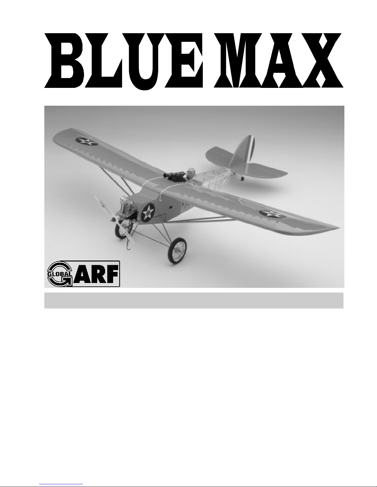
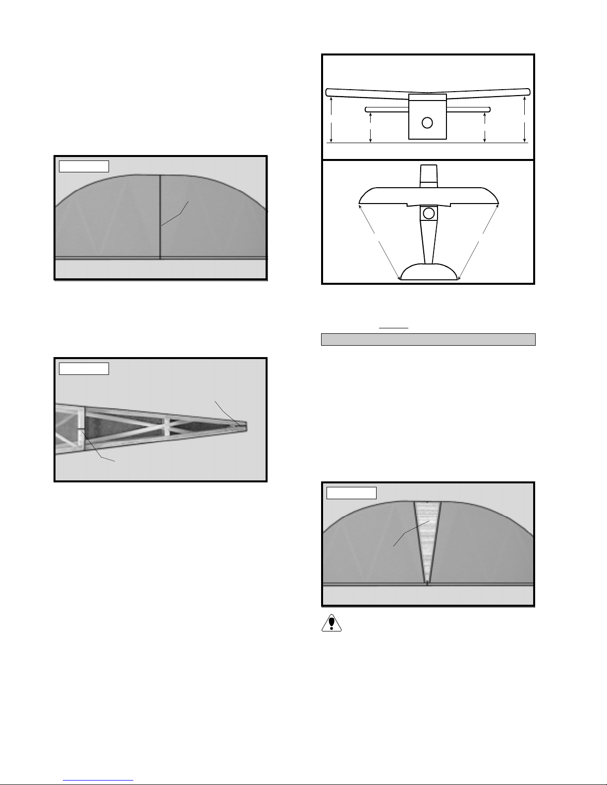
o 2) Using a ruler and a pen, locate and mark
the center section of the forward and rear dihedral braces (W-40 and W-41). Draw a vertical
line at this location on both braces. See photo
# 1 below .
Photo # 1
DRAW CENTERLINE
REAR
DIHEDRAL
BRACE
o 3) T est fit the dihedral braces into their respective boxes in each wing half. W-40 fits into
the forward box and W-41 fits into the rear box.
The braces should slide into each wing half up to
the centerlines. If they do not, remove them and
lightly sand the edges and tip of each one until the
proper fit is obtained. See photo # 2 below .
Photo # 2
SLIDE IN UP
TO CENTERLINE
SLIDE IN UP
TO CENTERLINE
The dihedral braces are cut in the shape of
a "V". They should be installed with the "V"
shape facing upright to form the proper dihedral
angle when the wings are joined.
o 4) T est fit both of the wing halves together
with the dihedral braces temporarily installed. Do
not glue them in at this time! The wing halves
should fit together tightly with little or no gaps in the
center section joint. If the center section joint is
not tight, remove the wing halves and lightly sand
the edges and tips of each brace. Reinstall the
wing halves and braces and test the fit until you are
satisfied that the center section joint is tight.
FORW ARD
DIHEDRAL
BRACE
DRAW CENTERLINE
o 5) When satisfied with the fit of the wing
halves, remove the dihedral braces.
5
JOINING THE WING HAL VES
o 6) Mix a generous amount of Kwik Bond
30 Minute Epoxy . W orking with only one wing
half for now , apply a thin layer of epoxy inside
both dihedral brace boxes and on only half of
each dihedral brace. Make sure to cover the top
and bottom as well as the sides and use enough
epoxy to fill any gaps.
WING MOUNTING
PARTS REQUIRED
o {1 } Fuselage
o { 2 } Wing Hold Down Dowels (W-43)
o {2} Wing Struts
o {6 } 3mm x 10mm Machine Screws
o {6 } 3mm Flat Washers
INSTALL THE WING HOLD DOWN DOWELS
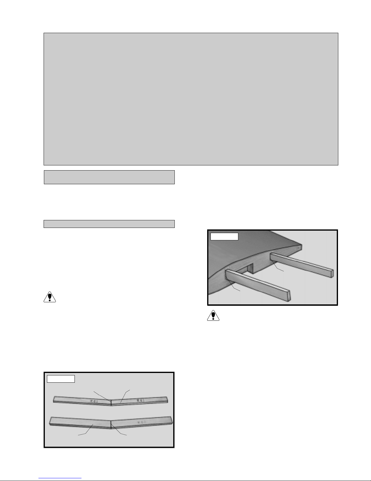
o 7) Slide the dihedral braces into the boxes
up to the centerlines. Remove any excess epoxy
before it dries using a paper towel and rubbing
alcohol. Allow the epoxy to cure before proceeding. See photo # 3 below.
Photo # 3
o 8) Once the epoxy has cured, trial fit both
wing halves together to double check that the wing
halves still fit correctly .
o 9) Mix a generous amount of Kwik Bond 30
Minute Epoxy . Apply a thin layer of epoxy to the
exposed halves of both dihedral braces, the inside
of both dihedral brace boxes i n the second wing
half and the entire surface of both root ribs. Make
sure to use enough epoxy to fill any gaps.
o 1) Using a modeling knife, carefully remove
the covering from over the four predrilled holes in
the fuselage sides. T wo holes are located on each
side of the fuselage. See photo # 5 below .
Photo # 5
REMOVE COVERING
REMOVE COVERING
(both sides)
(both sides)
o 2) Slide one wing hold down dowel through
the two forward holes in the fuselage sides and
the second dowel through the two rear holes in
the fuselage sides. Adjust the dowels so both
ends of each dowel protrude from the fuselage
sides an equal amount. See photo # 6 below.
Photo # 6
o 10) Slide the two wing halves together and
carefully align them at the leading and trailing edges.
Wipe away any excess epoxy using a paper towel
and rubbing alcohol. Use masking tape to hold the
wing halves in place until the epoxy cures. See
photo # 4 below .
Photo # 4
MASKING
TAPE
MASKING
TAPE
WING HOLD
DOWN DOWEL
o 3) When satisfied with the fit, use a pen and
place a mark on each dowel at the point where
they exit the fuselage sides.
o 4) Remove the dowels and mix a small
amount of Kwik Bond 30 Minute Epoxy . Apply
a thin layer of epoxy to the inside edges of all four
holes in the fuselage. Carefully slide the dowels
into place up to the marks made. Double check
that they are centered and use paper towels and
rubbing alcohol to remove any excess epoxy before it cures.
6
ALIGNING THE WING TO THE FUSELAGE
o 5) Using a ruler and a pen, locate and mark
the centerline of the fuselage at both the front and
rear of the wing saddle. Place a mark at both
locations. See photo # 7 below .
Photo # 7
MARK
CENTERLINE
MARK
CENTERLINE
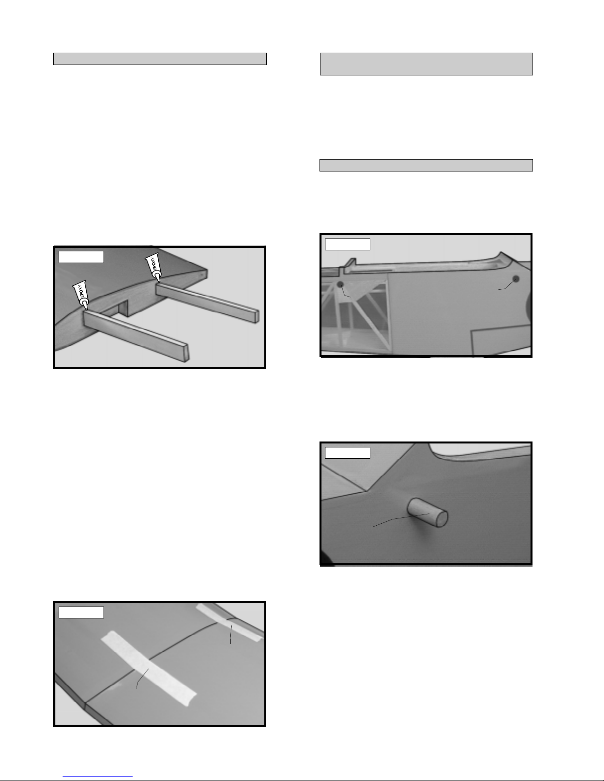
Photo # 9
REMOVE COVERING
WING TIP
AILERON
o 8) Place the wing into the wing saddle. Align
the centerline of the wing at both the leading and
trailing edges with the two marks you made on
the fuselage.
These two marks will help you align the wing
when you install it on the fuselage. Y ou may
wish to make these marks in permanent ink so
you can align the wing correctly each time you
install the wing. This will ensure the wing is aligned
properly each time you fly the airplane.
INST ALL THE WING STRUTS
o 6) There are two preinstalled blind nuts that
are used to mount the wing struts to the bottom
of the fuselage. Using a modeling knife, carefully remove the covering from over the two blind
nut holes on the bottom of the fuselage. The
holes are located 1/2” in from the fuselage sides
and 8-1/4” back from the front of the firewall.
See photo # 8 below .
Photo # 8
REMOVE
COVERING
8-1/4”
o 9) Using a couple of # 64 rubber bands,
temporarily secure the wing in place making sure
it is aligned. T o correctly install the rubber bands,
hook one over one of the front wing hold down
dowels, carefully pull it back over the top of the
wing and hook it over the rear hold down dowel
on the same side. Install two rubber bands on
each side for now .
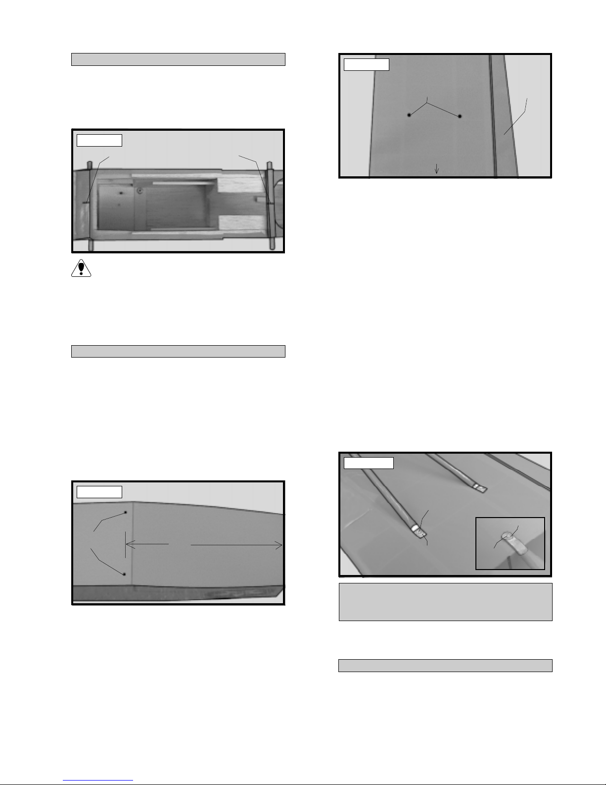
o 10) Bolt the wing struts to the wing and to
the fuselage using the six 3mm x 6mm machine
screws and six 3mm flat washers. It may be
necessary to move the wing slightly to properly
align the holes in the struts with the blind nuts.
See photo # 10 below .
Photo # 10
3mm x
6mm
SCREW
3mm FLAT
WASHER
3mm FLATWASHER
3mm x 6mm
SCREW
o 7) There are also two blind nuts preinstalled in
each wing half. They are located in plywood gussets, 20” out from the centerline of the wing. The
rear blind nut is 2-3/4” forward of the trailing edge
and the front blind nut is 3” back from the leading
edge. Using a modeling knife, carefully remove the
covering from over the two blind nut holes in each
wing half. See photo # 9 at top right.
HORIZONTAL STABILIZER
MOUNTING
PARTS REQUIRED
o {1} Horizontal Stabilizer w/Elevator and Hinges
ALIGN THE HORIZONT AL STABILIZER
o 1) Remove the elevator from the horizontal
stabilizer and set it aside for now . Turn the stabilizer upside down on your work surface. The bottom side is the flat side and should be facing up.
7
o 2) Using a ruler and a pen, locate and mark
the centerline of the horizontal stabilizer at the
trailing edge and place a mark. Use a triangle
and extend this mark, from back to front, across
the bottom of the stabilizer. Also place centerline marks on the top of the stabilizer at the leading
and trailing edges only. See photo # 11 below .
Figure # 1
B
A
A1
B1
Photo # 1 1
DRA W
CENTERLINE
o 3) Using a ruler and a pen, locate and place
a mark at the centerline of the fuselage at the front
and rear of the stabilizer mounting platform. These
marks will be used to line up the stabilizer with
the fuselage. See photo # 12 below .
Photo # 12
DRA W
CENTERLINE
DRAW
CENTERLINE
Figure # 2
C
C1
o 5) When you are satisfied with the alignment,
hold the stabilizer in place with T- pins or masking tape, but do not glue at this time.
MOUNTING THE HORIZONT AL STABILIZER
o 6) With the stabilizer held firmly in place, use
a pen and draw a line on the stabilizer where it
and the fuselage sides meet. Do this on both the
right and le ft sides on the bottom of the stabilizer.
o 7) Remove the stabilizer. Using the lines you
just drew as a guide, carefully remove the covering
from between them, using a modeling knife. See
photo # 13 below.
o 4) Attach the wing to the fuselage and remove both ailerons. Set the horizontal stabilizer
onto the stabilizer mounting platform on the fuselage. Align the centerline marks on top of the
stabilizer with the centerline marks at the front
and rear of the stabilizer mounting platform. When
the marks are aligned hold the stabilizer in position using a couple of T-pins. Align the horizontal
stabilizer with the wing. When viewed from the
rear, the horizontal stabilizer should be level with
the wing. If it is not level, use sandpaper and
sand down the high side of the stabilizer mounting platform until the proper alignment is achieved.
The tips of the stabilizer should also be equal distance from the tips of the wing. See figures # 1
and # 2 at top right.
Photo # 13
REMOVE
COVERING
When cutting through the covering to re-
move it, cut with only enough pressure to
only cut through the covering itself. Cutting into
the balsa structure may weaken it and cause possible failure in flight.
8
o 8) When you are satisfied that everything is
aligned correctly , mix up a generous amount of
Kwik Bond 30 Minute Epoxy . Apply a thin layer
to the bottom of the stabilizer mounting area and
to the top of the stabilizer mounting platform on
the fuselage. Set the stabilizer in place and realign. Double check all of your measurements
once more before the epoxy cures. Hold the stabilizer in place with T-pins or masking tape and
remove any excess epoxy using paper towels and
rubbing alcohol.
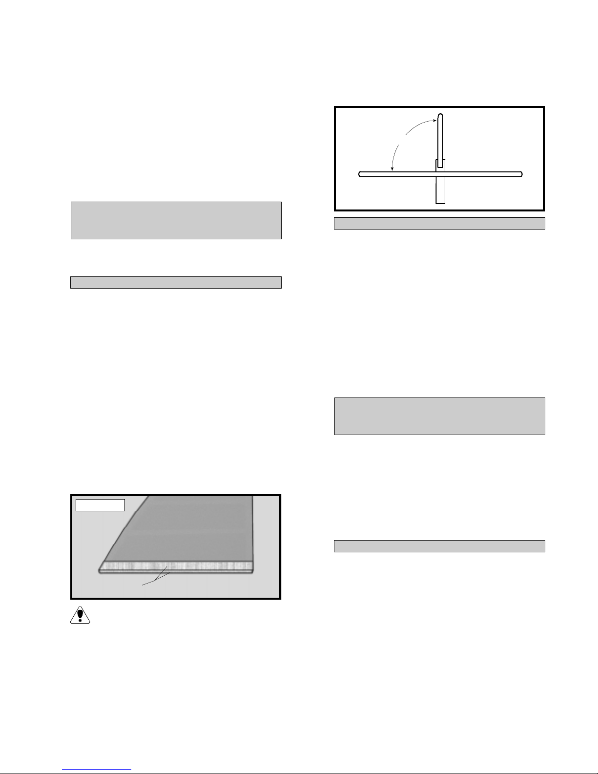
o 4) Set the vertical stabilizer back in place.
Using a triangle, check to ensure that the vertical
stabilizer is aligned 90º to the horizontal stabilizer .
See figure # 3 below .
Figure # 3
90º
VERTICAL STABILIZER
MOUNTING
PARTS REQUIRED
o {1} V ertical Stabilizer w/Rudder and Hinges
ALIGN THE VERTICAL ST ABILIZER
o 1) Remove the rudder from the stabilizer .
Slide the stabilizer into the slot in the top of the
horizontal stabilizer . The rear edge of the vertical
stabilizer should be even with the rear edge of the
horizontal stabilizer and fuselage. It should also
be pushed down completely into the slot.
o 2) Using a pen, draw a line on each side of
the vertical stabilizer where it meets the top of the
slot on the horizontal stabilizer.
o 3) Remove the stabilizer. Using a modeling
knife, remove the covering from just below the lines
you drew . Also remove the covering from the bottom edge of the stabilizer. See photo # 14 below .
Photo # 14
MOUNTING THE VERTICAL ST ABILIZER
o 5) When you are satisfied that everything is
aligned correctly , mix up a generous amount of
Kwik Bond 30 Minute Epoxy . Apply a thin layer
to the mounting slot in the top horizontal stabilizer
and to the sides and bottom of the vertical stabilizer mounting area. Set the stabilizer in place
and realign. Double check all of your measurements once more before the epoxy cures. Hold
the stabilizer in place with T-pins or masking tape
and remove any excess epoxy using paper towels and rubbing alcohol. Allow the epoxy to fully
cure before proceeding.
CONTROL SURFACE
INSTALLATION
PARTS REQUIRED
o {2} Ailerons w/Hinges
o { 1 } Elevator w/Hinges
o { 1 } Rudder w/Hinges
o { 1 } Tail Wheel W ire w/Mounting Bracket
o { 1} 25mm Diameter Tail Wheel
o {2 } Wheel Collars w/3mm x 6mm Machine Screws
o {3 } 3mm x 12mm W ood Screws
REMOVE
COVERING
When cutting through the covering to re-
move it, cut with only enough pressure to
only cut through the covering itself. Cutting into
the balsa structure may weaken it. There may
also be covering material overlapped on the inside edges of the vertical stabilizer mounting slot
in the horizontal stabilizer . Using a modeling knife,
carefully remove this covering also. This will help
insure a good glue joint.
HINGE THE AILERONS
o 1) The C/A hinges have already been glued
into the two ailerons. W orking with one aileron
at a time, slide the aileron and it's hinges into their
precut hinge slots in the trailing edge of the wing,
making sure the torque rod is firmly seated in the
precut hole in the leading edge of the aileron. Slide
the aileron in until it is tight against the trailing
edge of the wing. The maximum hinge gap should
be no more than 1/32” and the tip of the aileron
should be flush with the tip of the wing.
9
 Loading...