

Page 1
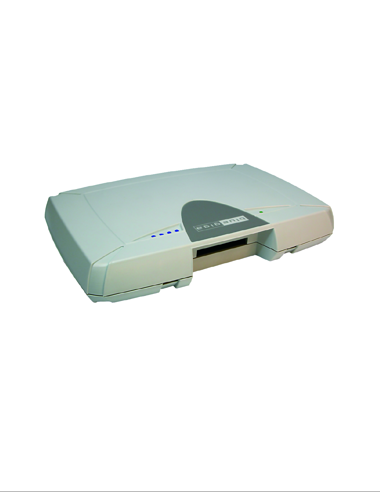
Access Server
User’s and Developer’s Guide
Bluegiga Technologies
Page 2

Access Server: User’s and Developer’s Guide
by Bluegiga Technologies
Published 2007-07-20 (3.2)
Copyright © 2001, 2002, 2003, 2004, 2005, 2006, 2007 Bluegiga Technologies
Bluegiga Technologies reserves the right to alter the hardware, software, and/or specifications detailed herein at any time without
notice, and does not make any commitment to update the information contained herein. Bluegiga Technologies assumes no
responsibility for any errors which may appear in this manual. Bluegiga Technologies’ products are not authorized for use as critical
components in life support devices or systems.
The WRAP is a registered trademark of Bluegiga Technologies. iWRAP, WRAP THOR and WRAP Access Server are trademarks of
Bluegiga Technologies.
The Bluetooth trademark is owned by the Bluetooth SIG Inc., USA, and is licensed to Bluegiga Technologies.
ARM and ARM9 are trademarks of ARM Ltd.
Linux is a trademark of Linus Torvalds.
All other trademarks listed herein belong to their respective owners.
Page 3

Table of Contents
1. Introduction to Access Server............................................................................................................1
1.1. Licenses and Warranty ............................................................................................................2
1.2. Bluegiga Technologies Contact Information ........................................................................2
2. Getting Started with Access Server..................................................................................................3
2.1. Powering Up .............................................................................................................................3
2.2. WWW Interface ........................................................................................................................4
2.3. Shell Prompt Access.................................................................................................................6
2.3.1. Management Console .................................................................................................7
2.3.2. Accessing Remotely.....................................................................................................8
2.3.3. Transferring Files to/from Access Server ................................................................8
2.4. Introduction to Configuration ................................................................................................9
2.5. Using the Setup WWW Interface ...........................................................................................9
2.6. Using the setup Command Line Application ....................................................................17
2.7. Resetting a Configuration .....................................................................................................18
2.8. Exporting and Importing Configurations...........................................................................18
3. Using the System ...............................................................................................................................19
3.1. Network Interfaces.................................................................................................................19
3.2. Bluetooth .................................................................................................................................19
3.2.1. iWRAP Password Protection ...................................................................................19
3.2.2. LAN Access Profile.................................................................................................... 20
3.2.3. Serial Port Profile .......................................................................................................20
3.2.4. Object Push and File Transfer Profile......................................................................21
3.2.5. PAN Profiles ...............................................................................................................24
3.2.6. Changing the Bluetooth Range................................................................................24
3.2.7. btcli ..............................................................................................................................25
3.2.8. serialbluetooth............................................................................................................25
3.3. Compact Flash Cards.............................................................................................................25
3.3.1. Compact Flash GPRS Cards .....................................................................................25
3.3.2. Compact Flash GPS Card .........................................................................................26
3.3.3. Compact Flash Wi-Fi Cards......................................................................................26
3.4. USB Memory Dongles and Compact Flash Memory Cards ............................................26
3.5. Servers......................................................................................................................................27
3.5.1. Finder ..........................................................................................................................28
3.5.2. ObexSender ................................................................................................................29
3.5.3. SMS Gateway Server................................................................................................. 29
3.5.4. User Level Watchdog ................................................................................................29
3.5.5. Remote Management ................................................................................................30
3.2.4.1. Incoming ObjP and FTP ...............................................................................21
3.2.4.2. Outgoing ObjP and FTP ...............................................................................22
3.5.5.1. Overview ........................................................................................................30
3.5.5.2. Management Packet Format........................................................................30
3.5.5.3. Management Packet Information File Format ..........................................31
3.5.5.4. Management Operation Example: Hello World.......................................31
3.5.5.5. Management Operation Example: Software Update...............................32
3.5.5.6. Management Operation Example: IPQUERY ...........................................32
iii
Page 4

3.5.5.7. Management Operation Example: Beep ....................................................33
3.5.5.8. Management with USB Memory Dongle or Compact Flash Memory
Card ....................................................................................................................33
3.5.5.9. Listing and Uninstalling Software Component........................................33
3.5.6. FTP ...............................................................................................................................33
3.5.7. Web Server ..................................................................................................................33
3.5.8. SNMP ..........................................................................................................................33
3.5.9. OpenVPN....................................................................................................................34
3.5.10. SSH.............................................................................................................................34
3.5.11. Telnet .........................................................................................................................34
3.5.12. NTP ............................................................................................................................34
3.6. Utilities.....................................................................................................................................34
3.7. Real Time Clock ......................................................................................................................39
3.8. Time Zone................................................................................................................................39
3.9. System Re-Install and Upgrade............................................................................................39
4. SPP-over-IP .........................................................................................................................................41
4.1. How SPP-over-IP Works .......................................................................................................41
4.1.1. Standard Operation...................................................................................................41
4.1.2. Repeater Operation ...................................................................................................42
4.1.3. SPP-over-IP over GPRS.............................................................................................42
4.1.4. Opening Connections from Access Server.............................................................43
4.1.5. SPP-over-IP and COM Ports ....................................................................................44
4.2. Configuring SPP-over-IP.......................................................................................................44
4.2.1. Forwarding Incoming Connections ........................................................................45
4.2.2. Maintaining and Forwarding Outgoing Connections..........................................45
4.2.3. Repeater Configuration ............................................................................................45
4.2.4. Wi-Fi Configuration ..................................................................................................46
4.2.5. GPRS Configuration ..................................................................................................46
5. Obexsender .........................................................................................................................................47
5.1. Key Features............................................................................................................................47
5.2. Use Cases.................................................................................................................................47
5.2.1. Content Push ..............................................................................................................48
5.2.2. Content Pull................................................................................................................48
5.3. Configuration..........................................................................................................................49
5.3.1. Uploading Files ..........................................................................................................49
5.3.2. Configuring Content Rules ......................................................................................50
5.3.3. How to Store Files Sent to Access Server ...............................................................50
5.4. Monitoring ObexSender........................................................................................................50
5.5. Bluetooth Device Database ...................................................................................................50
6. Software Development Kit ..............................................................................................................51
6.1. Introduction to SDK ...............................................................................................................51
6.2. Installing SDK.........................................................................................................................51
6.2.1. Access Server Software Development Kit System Requirements ......................51
6.2.2. Questions Asked by the Install Script.....................................................................52
6.3. Creating Applications............................................................................................................52
6.3.1. Application Examples...............................................................................................52
6.3.1.1. Installing Examples.......................................................................................52
iv
Page 5

6.3.1.2. Running Examples........................................................................................53
6.3.2. Creating a New Project .............................................................................................54
6.3.3. Building from the Command Line..........................................................................54
6.3.4. Transferring an Application to Access Server .......................................................55
6.3.4.1. Transferring an Application Using SCP or SFTP......................................55
6.3.4.2. Using SSHFS ..................................................................................................55
6.3.4.3. Transferring an Application Using Terminal Software ...........................55
6.3.4.4. Using NFS Mount .........................................................................................56
6.3.4.5. Using CIFS Mount ........................................................................................56
6.3.5. Running an Application Transferred to Access Server ........................................56
6.3.6. Using GNU Project Debugger (GDB) .....................................................................57
6.3.7. Native SDK .................................................................................................................57
7. iWRAP - The Bluetooth API ............................................................................................................59
7.1. Terms........................................................................................................................................59
7.2. Starting iWRAP ......................................................................................................................59
7.3. Writing iWRAP Applications ...............................................................................................59
7.3.1. Forklistener .................................................................................................................60
7.3.2. iWRAP Client .............................................................................................................60
7.4. btcli - iWRAP Command Line Interface Utility.................................................................60
7.5. iWRAP Commands................................................................................................................61
INFO ......................................................................................................................................61
QUIT ......................................................................................................................................62
SET .........................................................................................................................................63
SAVE......................................................................................................................................73
LOAD ....................................................................................................................................74
PING......................................................................................................................................75
PONG ....................................................................................................................................76
ECHO ....................................................................................................................................77
LOCK.....................................................................................................................................78
UNLOCK ..............................................................................................................................79
SHUTDOWN........................................................................................................................80
SLEEP ....................................................................................................................................81
LOG .......................................................................................................................................82
7.6. Finding Bluetooth Devices....................................................................................................84
INQUIRY...............................................................................................................................84
NAME ...................................................................................................................................85
7.7. Bluetooth Connections ..........................................................................................................86
CALL .....................................................................................................................................86
CONNECT............................................................................................................................88
NO CARRIER .......................................................................................................................90
RING......................................................................................................................................91
RINGING..............................................................................................................................92
CLOSE ...................................................................................................................................93
LIST........................................................................................................................................94
RSSI........................................................................................................................................96
TXPOWER ............................................................................................................................97
BER.........................................................................................................................................98
v
Page 6

CLOCK..................................................................................................................................99
STATUS ...............................................................................................................................100
7.8. Service Discovery .................................................................................................................101
SDPSEARCH......................................................................................................................101
SDPATTR ............................................................................................................................103
SDPQUERY.........................................................................................................................105
SDP bdaddr ........................................................................................................................106
SDP ADD ............................................................................................................................107
SDP DEL..............................................................................................................................108
SDP LIST .............................................................................................................................109
7.9. Example Sessions .................................................................................................................110
7.10. Error Codes .........................................................................................................................110
8. I/O API ...............................................................................................................................................114
8.1. Led and Buzzer API .............................................................................................................114
8.2. GPIO API...............................................................................................................................114
9. Finder Protocol .................................................................................................................................115
9.1. Finder Search Message ........................................................................................................115
9.2. Finder Reply Message .........................................................................................................115
10. Advanced Use Cases for Access Server .....................................................................................116
10.1. Making Access Server Secure ...........................................................................................116
10.2. Saving Bluetooth Pairing Information Permanently.....................................................116
10.3. Digital Pen ...........................................................................................................................116
10.4. OpenVPN ............................................................................................................................117
10.4.1. Prerequisites ...........................................................................................................117
10.4.2. Installing OpenVPN ..............................................................................................117
10.4.3. Creating Certificates and Keys ............................................................................118
10.4.4. Creating Configuration Files................................................................................120
10.4.4.1. Server Configuration File.........................................................................120
10.4.4.2. Client Configuration File .........................................................................122
10.4.5. Starting up VPN.....................................................................................................124
10.4.5.1. Starting up the Server...............................................................................124
10.4.5.2. Starting up the Client ...............................................................................125
11. Certification Information and WEEE Compliance ..................................................................126
A. Directory Structure .........................................................................................................................129
B. Setup Options ..................................................................................................................................131
B.1. Security settings ...................................................................................................................131
B.2. Generic settings....................................................................................................................133
B.3. Network settings..................................................................................................................135
B.3.1. Default interface settings .......................................................................................136
B.3.2. Ethernet cable settings............................................................................................137
B.3.3. Wi-Fi settings ...........................................................................................................137
B.3.4. GPRS settings...........................................................................................................138
B.4. Applications..........................................................................................................................139
B.4.1. FTP server settings..................................................................................................140
B.4.2. ObexSender settings ...............................................................................................141
B.4.2.1. Timeouts and delays ..................................................................................143
vi
Page 7

B.4.2.2. Logging ........................................................................................................144
B.4.2.3. Delete log (confirm)....................................................................................145
B.4.3. Connector settings...................................................................................................146
B.4.4. wpkgd settings ........................................................................................................147
B.4.5. SMS gateway settings .............................................................................................148
B.5. iWRAP settings ....................................................................................................................149
B.5.1. Bluetooth profiles ....................................................................................................152
B.5.1.1. LAN access profile settings .......................................................................152
B.5.1.2. PAN user profile settings...........................................................................153
B.5.1.3. PAN generic networking profile settings................................................154
B.5.1.4. PAN network access point profile settings .............................................155
B.5.1.5. Connection forwarding..............................................................................155
B.5.1.6. Serial port profile settings .........................................................................155
B.5.1.7. Object push profile settings.......................................................................157
B.5.1.8. File transfer profile settings.......................................................................157
B.6. Advanced settings ...............................................................................................................158
B.6.1. Bluetooth commands ..............................................................................................159
B.6.2. System information.................................................................................................159
B.6.3. Reboot system (confirm) ........................................................................................160
B.7. Summary of Setup Options ................................................................................................160
C. Open Source Software Licenses...................................................................................................166
D. Supported Hardware .....................................................................................................................171
vii
Page 8

List of Tables
2-1. The Management Console Port Settings ........................................................................................7
3-1. Access Server Network Interfaces.................................................................................................19
3-2. obexserver ’s metas ..........................................................................................................................21
3-3. Parameters for obexsender-put .....................................................................................................22
3-4. Errorlevels from obexsender-put ..................................................................................................23
3-5. Parameters for obexsender-inquiry ..............................................................................................24
3-6. Errorlevels from obexsender-inquiry ...........................................................................................24
3-7. Access Server Servers......................................................................................................................27
3-8. Access Server Utilities.....................................................................................................................34
6-1. Examples, Their Usage and Purpose ............................................................................................53
7-1. Supported Parameters for iWRAP SET Command....................................................................63
7-1. SAVE parameters.............................................................................................................................73
7-1. Log bitmask descriptions ...............................................................................................................82
7-2. Log target options............................................................................................................................82
7-5. Supported Keywords for Replacing SDP UUIDs or Attributes..............................................101
7-1. SDP Response Formatting Characters........................................................................................103
7-7. iWRAP Errors.................................................................................................................................110
7-8. Errors Masks...................................................................................................................................111
7-9. HCI Error Codes ............................................................................................................................111
7-10. L2CAP Error Codes .....................................................................................................................112
7-11. SDP Error Codes ..........................................................................................................................113
7-12. RFCOMM Error Codes ...............................................................................................................113
9-1. Finder Tuple Format......................................................................................................................115
9-2. Finder Tuple IDs ............................................................................................................................115
11-1. Excerpt of Table 1B of 47 CFR 1.1310........................................................................................127
C-1. Open Source Licenses in Access Server Software Components ............................................166
C-2. Access Server Open Source Software Components and Their Licences...............................166
D-1. Supported Hardware by Access Server ....................................................................................171
viii
Page 9

Chapter 1. Introduction to Access Server
Bluegiga’s WRAP™ product family offers for device manufacturers, integrators, companies and
developers a simple and fast way to set-up wireless communication systems between standard
or proprietary devices, networks, machines and instruments.
Access Server is a cutting edge wireless Bluetooth router. It supports multiple communication
standards including Ethernet, WiFi, and GSM/GPRS enabling full media-independent TCP/IP
connectivity. Access Server is easy to deploy and manage in existing wired and wireless networks without compromising speed or security. For rapid deployment, Access Server configurations can easily be copied from one device to another by using USB memory dongles. The
device can be fully managed and upgraded remotely over SSH secured links. Large numbers of
Access Servers can easily be controlled using Bluegiga Solution Manager (BSM), a web-based
remote management and monitoring platform.
Access Server usage scenarios and applications:
• Point-of-sales systems
• Logistics and transportation systems
• Telemetry and machine-to-machine systems
• Medical and healthcare systems
• Fitness and sport telemetry systems
• Cable replacement
• Content and application distribution to mobile phones and PDAs
Access Server key features:
• Enables Bluetooth networking between multiple devices and networks
• Serves up to 21 simultaneous Bluetooth connections
• Offers an open platform for adding local applications
• Acts as a transparent router or bridge
• Supports all key communication medias:
• Bluetooth
• Ethernet
• WiFi, GSM and GPRS with a Compact Flash card
• USB and RS232
• Incorporates a packet filtering firewall
• Is fast and easy to install
• Supports all relevant Bluetooth profiles and APIs
• 100 meter range / Software configurable to support 10 meter range
• DHCP support for plug-and-play installation
• Uncompromised security: SSH, firewall, and 128 bit Bluetooth encryption
1
Page 10

• Simple and secure mounting accessory available
• Bluetooth, CE, and FCC certified
• Compliant with Bluetooth 1.1, 1.2 and 2.0 Specification
1.1. Licenses and Warranty
Bluegiga Technologies is hereby willing to license the enclosed WRAP product and
its documentation under the condition that the terms and conditions described in
the License Agreement are understood and accepted. The License Agreement is
supplied within every WRAP product both in hard copy. It is also available on-line
at http://bluegiga.com/as/current/doc/eula.pdf. The use of the WRAP product
will indicate your assent to the terms. If you do not agree to these terms, Bluegiga
Technologies will not license the software and documentation to you, in which
event you should return this complete package with all original materials, equipment, and media.
Some software components are licensed under the terms and conditions of an open source license. Details can be found in
machine-readable copy of the source of the aforementioned open source software components
during a period of three (3) years from the release date of the software. Delivery costs of the
source code will be charged from the party requesting the source code.
Chapter 1. Introduction to Access Server
Warning
Appendix C. Upon request, Bluegiga will distribute a complete
The Bluegiga WRAP Product Limited Warranty Statement is available on-line at
http://bluegiga.com/as/current/doc/warranty.pdf.
1.2. Bluegiga Technologies Contact Information
Please see http://www.bluegiga.com/ for news and latest product offers. For more information,
contact <[email protected]>.
Please check http://bluegiga.com/as/ for software and documentation updates.
Please contact <[email protected]> if you need more technical support. To speed up the
processing of your support request, please include as detailed information on your product and
your problem situation as possible.
Please begin your email with the following details:
• Access Server product type
• Access Server product serial number
• Access Server software version
• End customer name
• Date of purchase
2
Page 11
Chapter 2. Getting Started with Access Server
Access Server can be controlled in three ways:
• by using the WWW interface
• by entering commands and using applications at the Access Server shell prompt
• by sending and/or retrieving files to/from Access Server.
Note: The default username is root and the default password is buffy.
2.1. Powering Up
To get started with Access Server, connect it to your local area network (LAN) by using an
Ethernet cable, and connect the power adapter. Access Server will power up and retrieve the
network settings from your network’s DHCP server.
Access Server will also use Zeroconf (also known as Zero Configuration Networking or Automatic Private IP Addressing) to get an unique IP address in the 169.254.x.x network. Most
operating systems also support this. In other words, you can connect your controlling laptop
with a cross-over Ethernet cable to Access Server, then power up Access Server, and the devices
will automatically have unique IP addresses in the 169.254.x.x network.
Note: If you need to configure the network settings manually and cannot connect first by using Zeroconf, you can do it by using the management console. For more information, see Section 2.3.1.
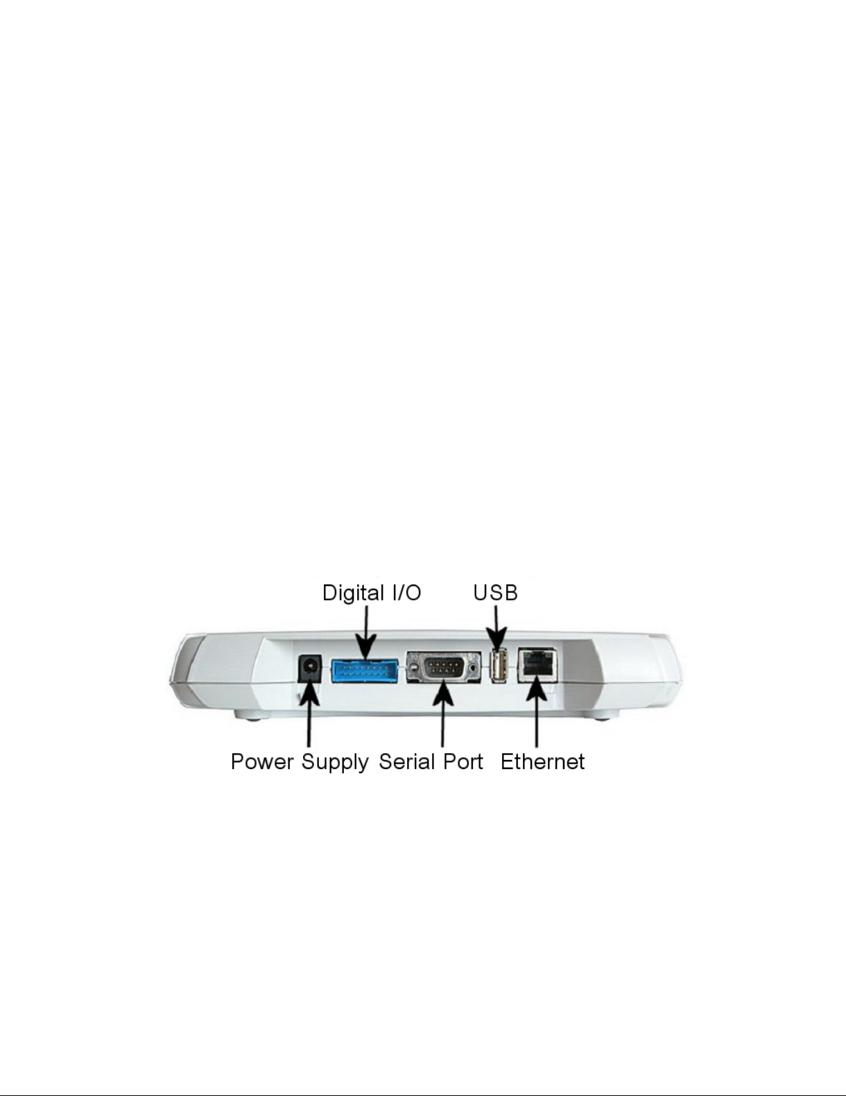
The physical interface locations of Access Server are described in Figure 2-1 and Figure 2-2.
Figure 2-1. Access Server Connectors
Note: There is no power switch in Access Server. The adapter is the disconnection device; the socketoutlet shall be installed near the equipment and shall be easily accessible. Unplug and plug the power
adapter to switch the power on and off. The power led in
connected.
Figure 2-2 is on when the power adapter is
3
Page 12
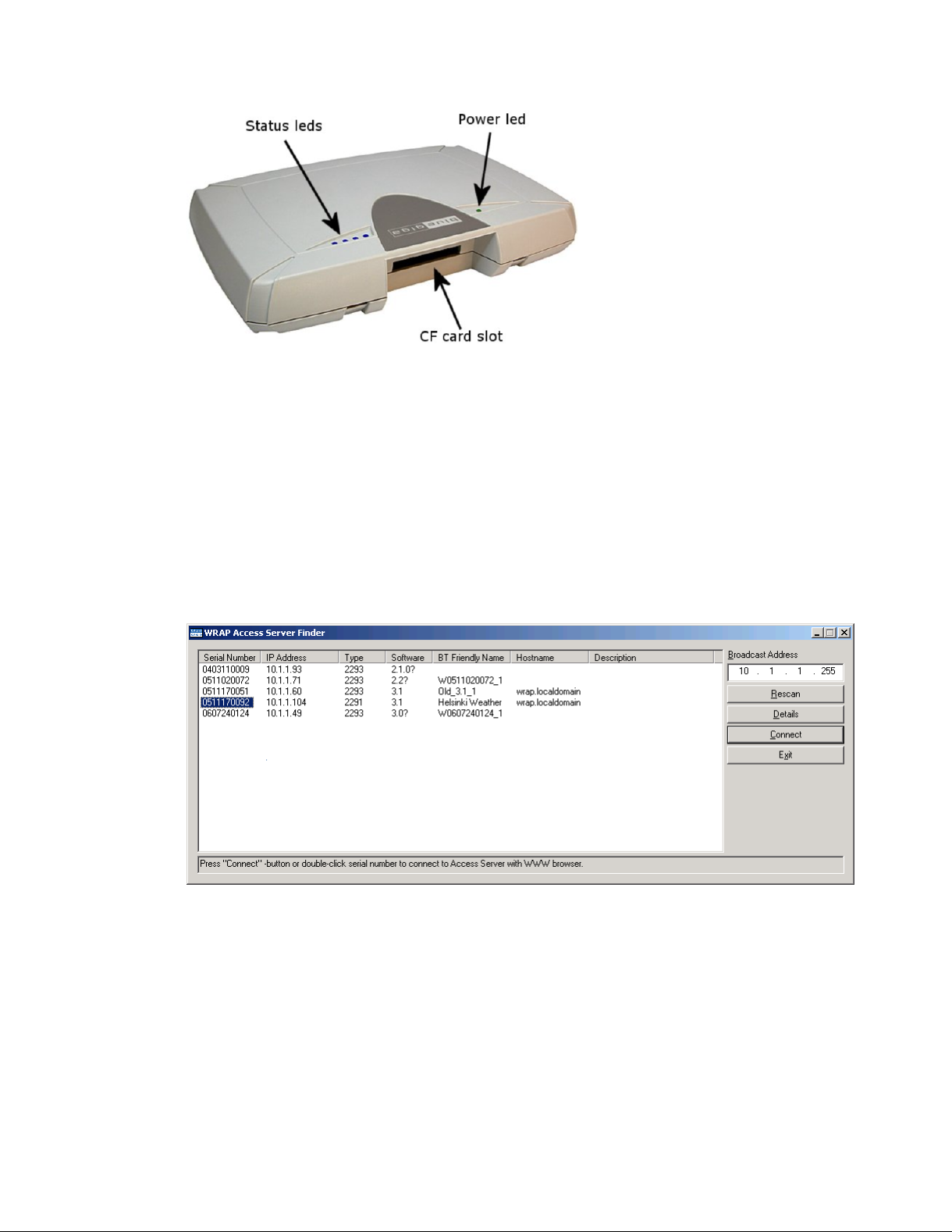
Figure 2-2. Access Server LEDs
All the blue status LEDs are turned off when the boot procedure is finished and Access Server
is ready to be connected.
2.2. WWW Interface
Most Access Server functionality can be controlled through the WWW interface by using any
standard WWW browser.
Chapter 2. Getting Started with Access Server
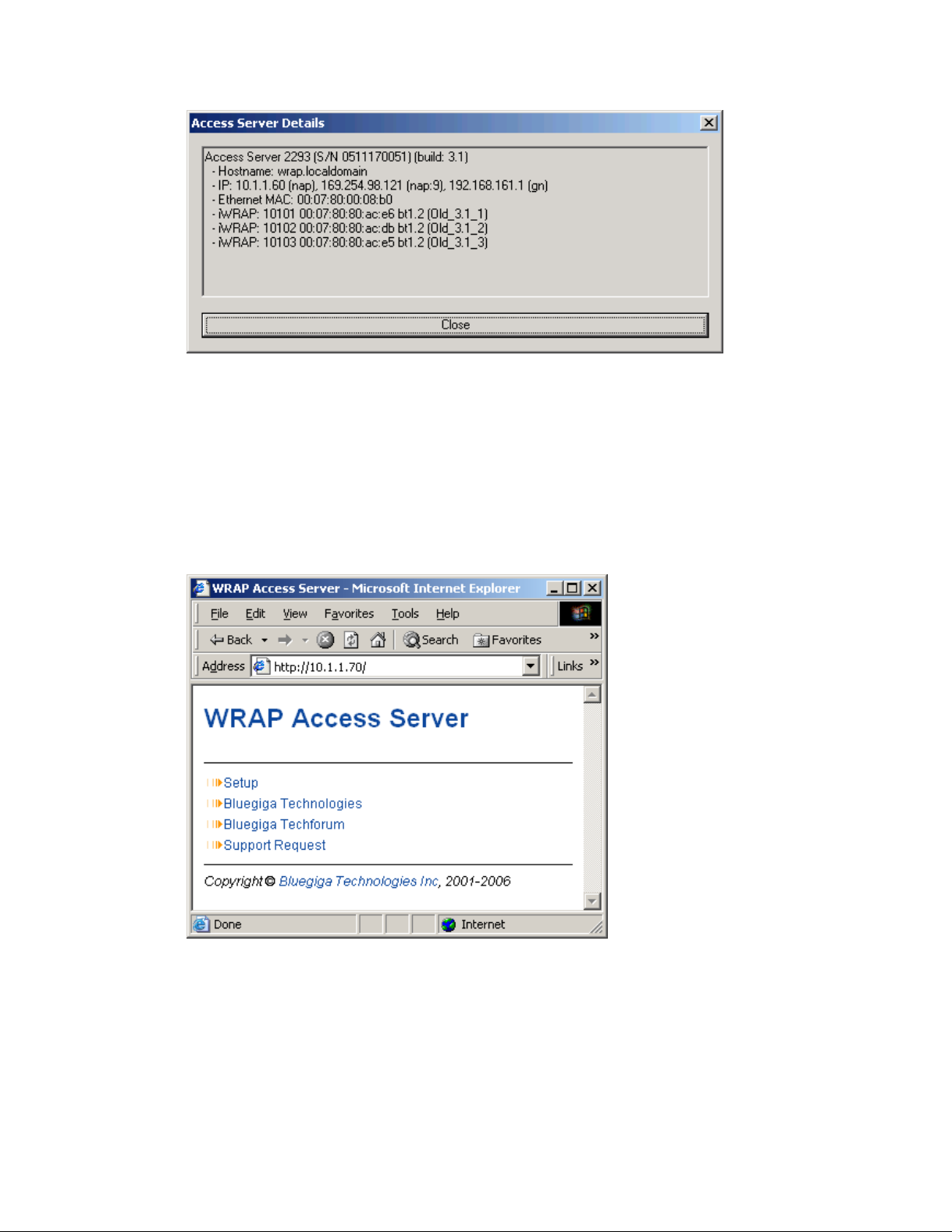
The wrapfinder application (see Figure 2-3), available for the Windows operating system from
Bluegiga Techforum (http://www.bluegiga.com/techforum/) provides an easy-to-use interface
for finding Access Servers (with SW version 2.1.0 or later) in the local area network.
Figure 2-3. Access Server Finder Application
When wrapfinder is launched, it automatically identifies the broadcast address of the network
it runs in and sends a special query packet (UDP broadcast) to Access Servers. Most important
information in their answers is then shown in table format.
You can change the broadcast address used for finding Access Servers. A new scan can be done
by clicking Rescan.
Select an Access Server by clicking its serial number, and click Details to see more information
(such as all Bluetooth addresses and friendly names) on Access Server. See Figure 2-4 for details.
4
Page 13
Chapter 2. Getting Started with Access Server
Figure 2-4. Details Dialog of Access Server Finder
Click Connect or double-click a serial number to connect to the selected Access Server by using
a WWW browser.
Click Exit to close the program.
Note: To find Access Server ’s IP address without wrapfinder, see Section 2.3.2.
To access the WWW interface, enter the IP address of Access Server to the browser’s address
field and press Enter (see Figure 2-5).
Figure 2-5. Access Server WWW Interface
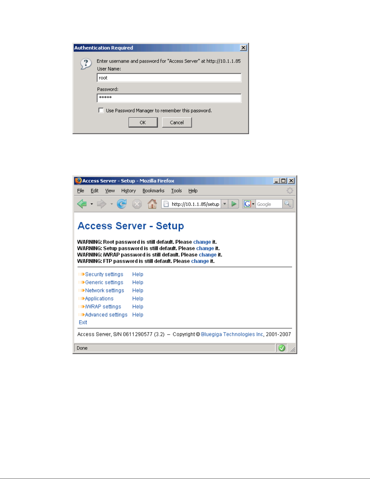
From the top-level page, click Setup to log in to the configuration interface. The default username is root and the default password is buffy (see Figure 2-6).
5
Page 14
Chapter 2. Getting Started with Access Server
Figure 2-6. WWW Login Prompt for Access Server Setup
After logging in, you can configure several Access Server settings (see
discussed in detail in Section 2.4.
Figure 2-7). These are
Figure 2-7. The WWW Configuration Interface of Access Server
2.3. Shell Prompt Access
Shell prompt access may be needed for advanced controlling operations that cannot be performed by using the WWW interface.
You can get to the shell prompt by using either SSH or the management console. The management console is only needed to change the network configuration settings if you cannot config-
6
Page 15

Chapter 2. Getting Started with Access Server
ure the network by using DHCP or Zeroconf. The management console is connected to Access
Server with a serial cable. All further controlling activities can be performed remotely using SSH
sessions over Ethernet or Bluetooth LAN/PAN connection.
If you can establish an SSH connection from a device that has Bluetooth LAN Access or PAN profile support, you do not need the management console. Just connect to Access Server by using
LAN Access or PAN profile. Access Server can be seen in Bluetooth inquiries as "Wserialno_n",
where "serialno" is the serial number of the device and "n" is the number of the Bluetooth baseband in question (model 2293 has three Bluetooth basebands, any of which can be connected).
After you have connected to the server (no PIN code, username or password needed), establish
an SSH connection to the device at the other end of the connection, typically 192.168.160.1. You
can also use the wrapfinder application to find the IP address (see Section 2.2 for details).
Note: Bluetooth LAN Access and PAN profiles are disabled by default. Use the WWW interface to
enable them, if needed. The PAN profile can also be enabled by sending the enable-pan.wpk file
(available on-line at http://bluegiga.com/as/current/enable-pan.wpk) to Access Server by using
Bluetooth Object Push profile or by inserting a USB memory dongle with the file in its root directory to Access Server’s USB port.
Note: The default username is root and the default password is buffy.
2.3.1. Management Console
If you do not have a Bluetooth LAN/PAN client and if Access Server is not connected to your
LAN, or if you do not know the IP address given to Access Server, you can get the first shell
prompt access by using the management console.
To setup the management console, proceed as follows:
1. Have a PC with a free COM port.
2. Power off Access Server.
3. Configure your terminal application, such as HyperTerminal in Windows, to use the settings
below for your computer’s free COM port
Setting Value
Speed 115200bps
Data Bits 8
Parity None
Stop Bits 1
Flow Control None
Table 2-1. The Management Console Port Settings
4. Connect the serial cable shipped with Access Server to your PC’s free COM port.
5. Connect the serial cable to the management (user) port in Access Server (see Figure 2-1).
6. Power on Access Server.
7. Enter letter b in the terminal application during the first five seconds, while the blue LEDs
in Access Server turn on one by one.
8. The management console is now activated and you can see the boot log in your terminal
window.
7
Page 16

Chapter 2. Getting Started with Access Server
Note: The boot process may stop at the following U-Boot prompt:
Hit any key to stop autoboot: 0
U-Boot>
If this happens, enter command boot to continue to boot Linux.
9. Wait for the device to boot up and end with the following prompt:
Please press Enter to activate this console.
10. Press Enter to activate the console. You will be logged in as root in directory /root:
[root@wrap root]
11. You can now control Access Server from the management console.
2.3.2. Accessing Remotely
When Access Server is connected to a LAN, it tries to get the IP address by using DHCP and
Zeroconf by default. You can then use the wrapfinder application to find the IP address (see
Section 2.2).
If you cannot get the IP address by using the wrapfinder, another way to see the IP address of
Access Server is to connect with a management console (see previous section), power on the
unit and, after the system is up and running, give the ifconfig nap command. The inet addr
field for the nap interface contains the IP address of Access Server. For example, in the following
capture from the management console, the IP address is 192.168.42.3.
[root@wrap /]$ ifconfig nap
nap Link encap:Ethernet HWaddr 00:07:80:00:BF:01
inet addr:192.168.42.3 Bcast:192.168.42.255 Mask:255.255.255.0
inet6 addr: fe80::207:80ff:fe00:bf01/64 Scope:Link
UP BROADCAST MULTICAST MTU:1500 Metric:1
RX packets:12635 errors:0 dropped:0 overruns:0 frame:0
TX packets:8 errors:0 dropped:0 overruns:0 carrier:0
collisions:0 txqueuelen:100
RX bytes:1686246 (1.6 MiB) TX bytes:1640 (1.6 KiB)
Interrupt:24 Base address:0xc000
You can use this address to connect to Access Server remotely over SSH, SCP or SFTP.
Note: The default username is root and the default password is buffy.
2.3.3. Transferring Files to/from Access Server
You can transfer files to and from Access Server by using, for example:
• SCP (secure copy over SSH)
• SFTP (secure FTP connection over SSH)
• FTP (plain FTP connection)
Note: FTP is disabled by default for security reasons. Use SFTP instead.
8
Page 17

Chapter 2. Getting Started with Access Server
Tip: If enabled, use the integrated FTP client on the Internet Explorer (type ftp://root:buffy@wrapip-address/ in the address bar)
• Bluetooth OBEX (Object Push and File Transfer Profiles) to/from directory /tmp/obex in Ac-
cess Server
• NFS (mount an NFS share from a remote computer as a part of Access Server ’s file system)
• SSHFS (mount an Access Server directory over SSH as a part of any other Linux host file
system)
To download and install SSHFS, visit http://fuse.sourceforge.net/sshfs.html.
• CIFS (mount a Common Internet File System share from a remote computer as a part of Access
Server’s file system). A CIFS client, available in a separate installation packet, is required.
• USB memory dongle (see Section 3.4 for more information).
• Xmodem/Ymodem/Zmodem (use rz/rx/rb/sz/sx/sb commands from the management con-
sole)
For examples of transferring files, see
Section 6.3.4.
2.4. Introduction to Configuration
When Access Server is installed and powered up for the first time, the default configuration
settings are being used. With these settings, Access Server automatically configures its network
settings assuming that it is connected to a LAN network with a DHCP server running. Additionally, Access Server also uses Zero Configuration Networking (also known as Automatic Private
IP Addressing) to connect to the 169.254.x.x network, which can be used if the network has no
DHCP server.
After booting up, the only Bluetooth profiles enabled are the Object Push and File Transfer Profiles, used to send files to/from Access Server.
More Bluetooth profiles can be enabled, and most of Access Server settings can be configured
by using the setup application. It has a WWW interface at http://wrap-ip/setup but it can also
be run at the command line.
All configurable settings in the setup application are listed in Appendix B with short help texts.
Note: The default username is root and the default password is buffy.
2.5. Using the Setup WWW Interface
The easiest way to change Access Server settings is to use the WWW interface. Accessing the
WWW interface is instructed in Section 2.2.
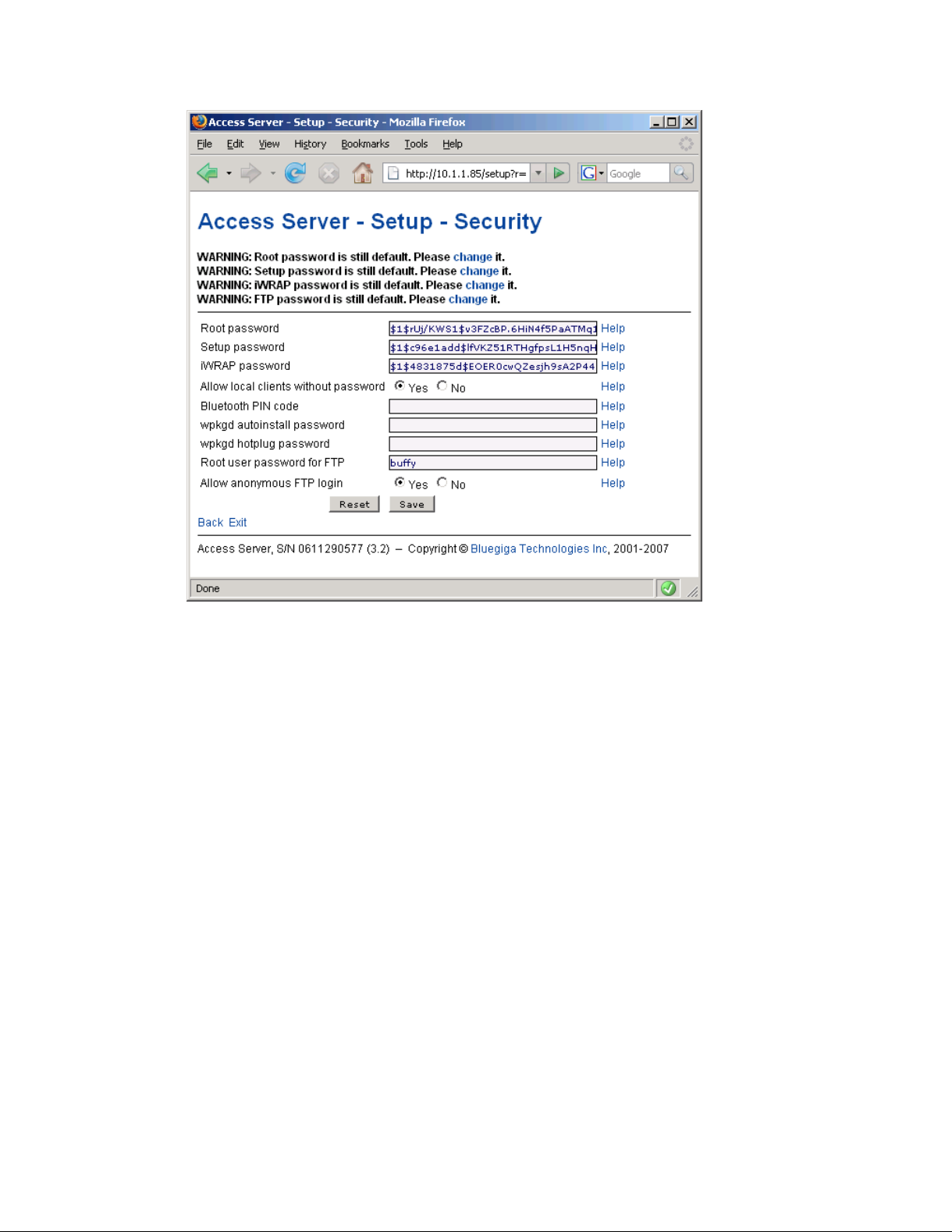
A typical WWW configuration page is shown in Figure 2-8 (This page can be found at Setup
−→ Security settings)
9
Page 18
Chapter 2. Getting Started with Access Server
Figure 2-8. Example WWW Setup Page
The different parts of the WWW Setup page are discussed in the following list:
• Status area
The status area serves two purposes:
• It indicates that the changes are permanently saved when the user clicks the Save button
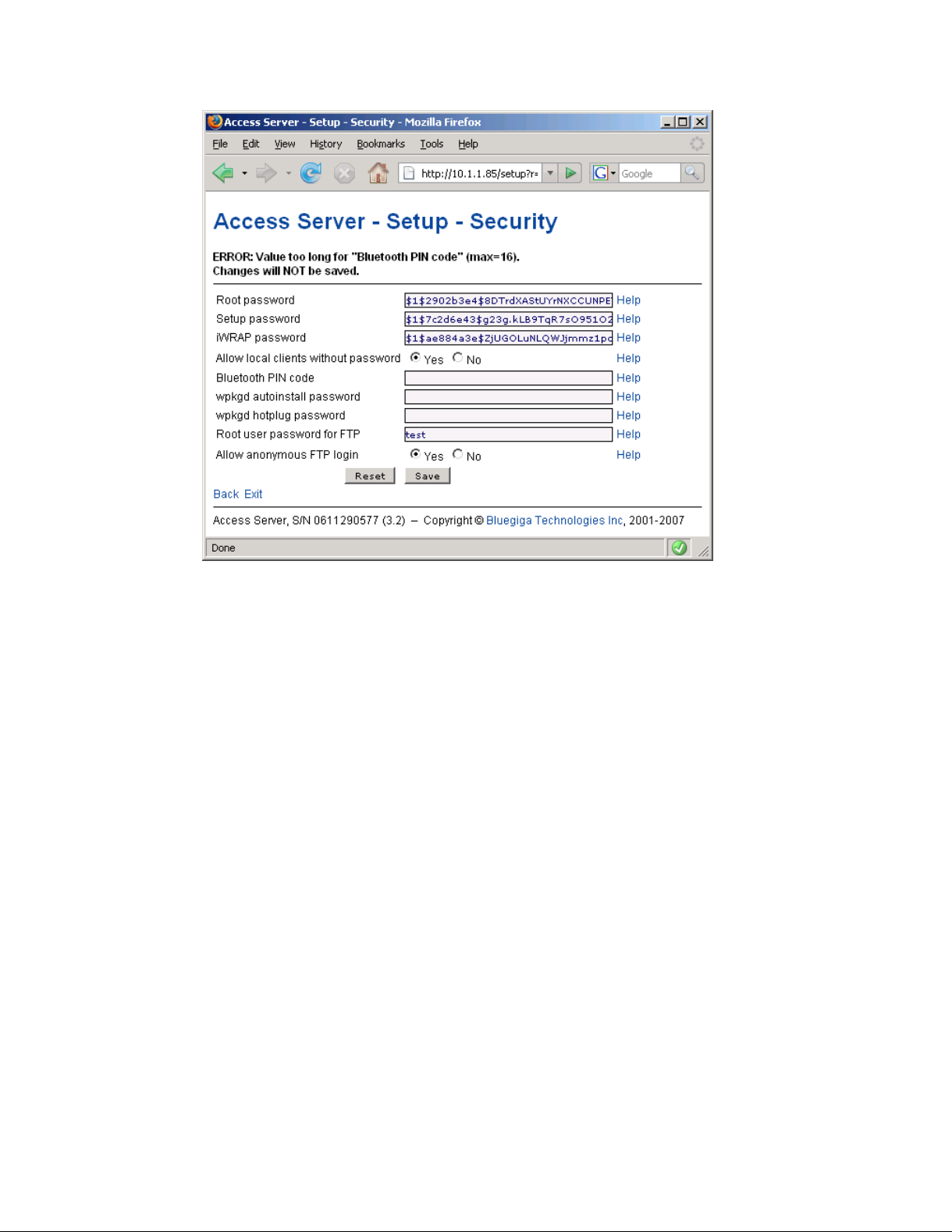
(or when the user clicks a toggling Yes/No link).
• If invalid values were entered in one or more fields, an error message is shown in this area
(see
Figure 2-9).
10
Page 19
Chapter 2. Getting Started with Access Server
Figure 2-9. Trying to Save an Invalid Input
Note: It is typically necessary to reboot Access Server for the changes to take effect. This can be
done through the WWW interface (Advanced settings menu).
• Number or text entry fields
Most of the configurable settings are text (or number) entry fields. For some fields, such as
the IP address or netmask, there are restrictions on the input format. Setup validates the input
at save time and accepts valid data only. The fields with errors are shown to the user so that
mistakes can be fixed (see Figure 2-9).
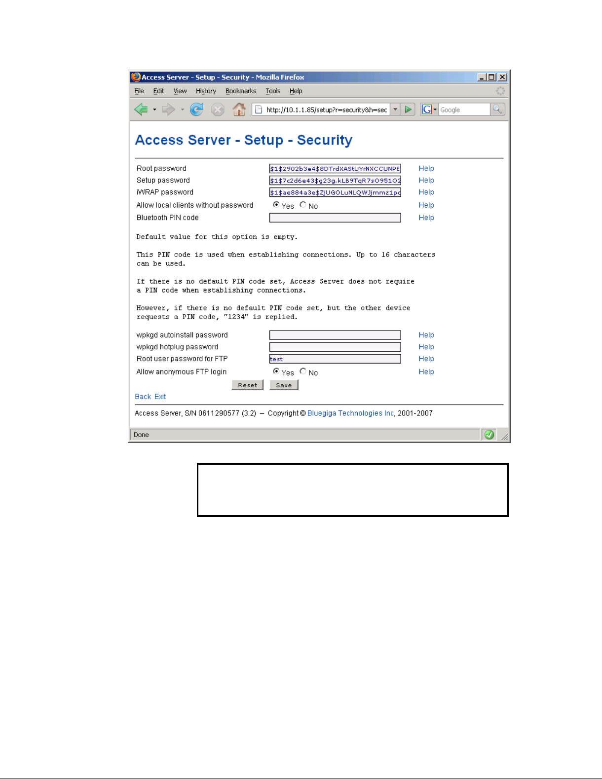
• Help -link
Click the Help link to retrieve the setup page again with requested help information displayed.
For an example, see Figure 2-10.
11
Page 20
Chapter 2. Getting Started with Access Server
Figure 2-10. Help Links in WWW Setup
Warning
If you have made changes to the settings on the page before clicking Help and
not saved them yet, they are lost.
• Yes and No radio buttons
These buttons are typically used to configure a setting that can be either enabled or disabled,
and this setting has no effect on the visibility of other settings.
• Reset button
Reset button resets the fields to the values currently in use at Access Server. In other words,
the Reset button discards unsaved changes.
Note: The Reset button does not make a "factory reset".
• Save button
Save button sends the WWW page to the setup application for validation. If the values in the
fields are valid, they are permanently saved and the page is refreshed with the Changes have
been saved. message at the top. The accepted values are shown in the page fields.
12
Page 21
Chapter 2. Getting Started with Access Server
If there were errors in the fields, these are shown as in Figure 2-9.
Note: It is typically necessary to reboot Access Server for the changes to take effect. This can be
done through the WWW interface (Advanced settings menu).
• Back link
Press the Back link to return to the previous level of the Setup menu hierarchy.
Note: Pressing the Back link does not save changes in the fields on the current page.
• Exit link
Exit link quits the setup application and returns to the Access Server’s main WWW page.
Note: Pressing the Exit link does not save changes in the fields on the current page.
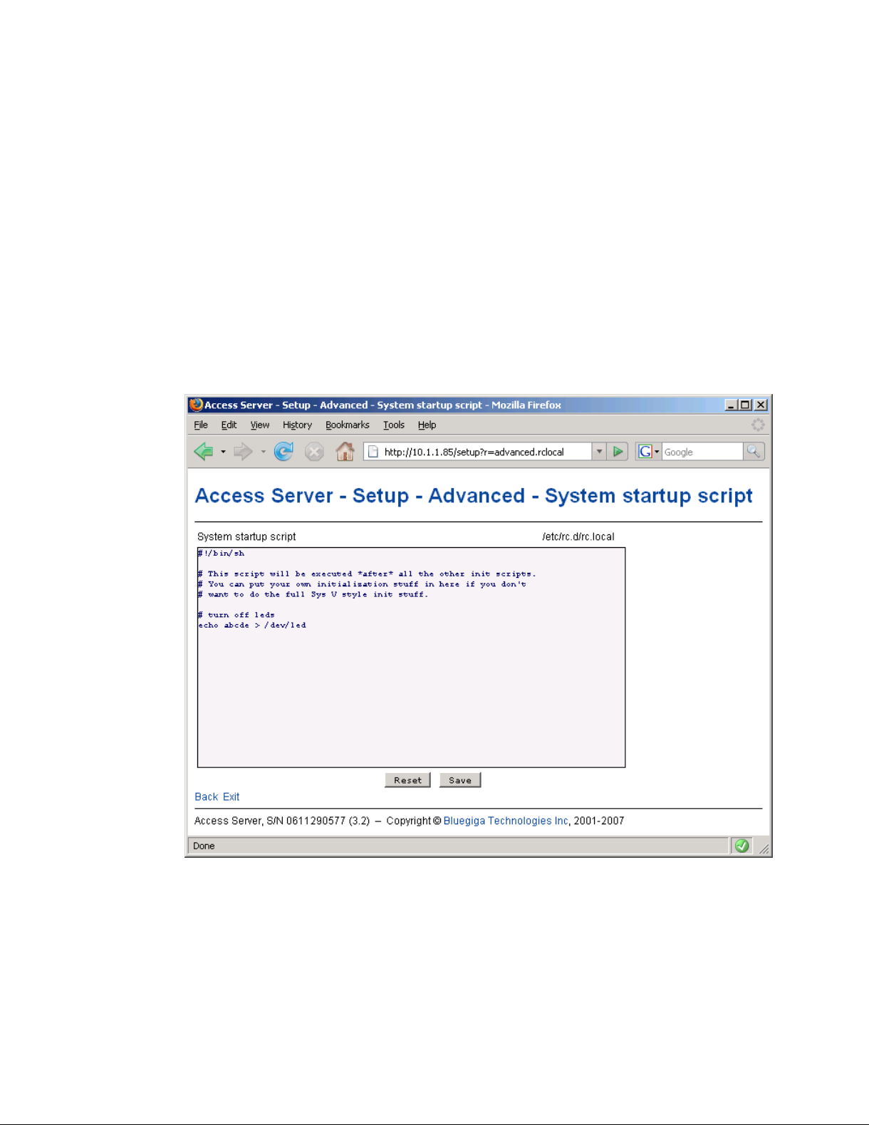
• Link to a configuration file
Some of the configurable settings are actually editable configuration files, such as
/etc/rc.d/rc.local for Setup −→ Advanced setting −→ System startup script. Clicking
the link will retrieve the file for editing in the browser window, or create a new file, if it does
not exist. See Figure 2-11.
Figure 2-11. Editing Files in WWW Setup
Note: You can edit any file through the WWW Setup. to edit files, navigate to Setup −→ Advanced
setting −→ Edit other configuration files.
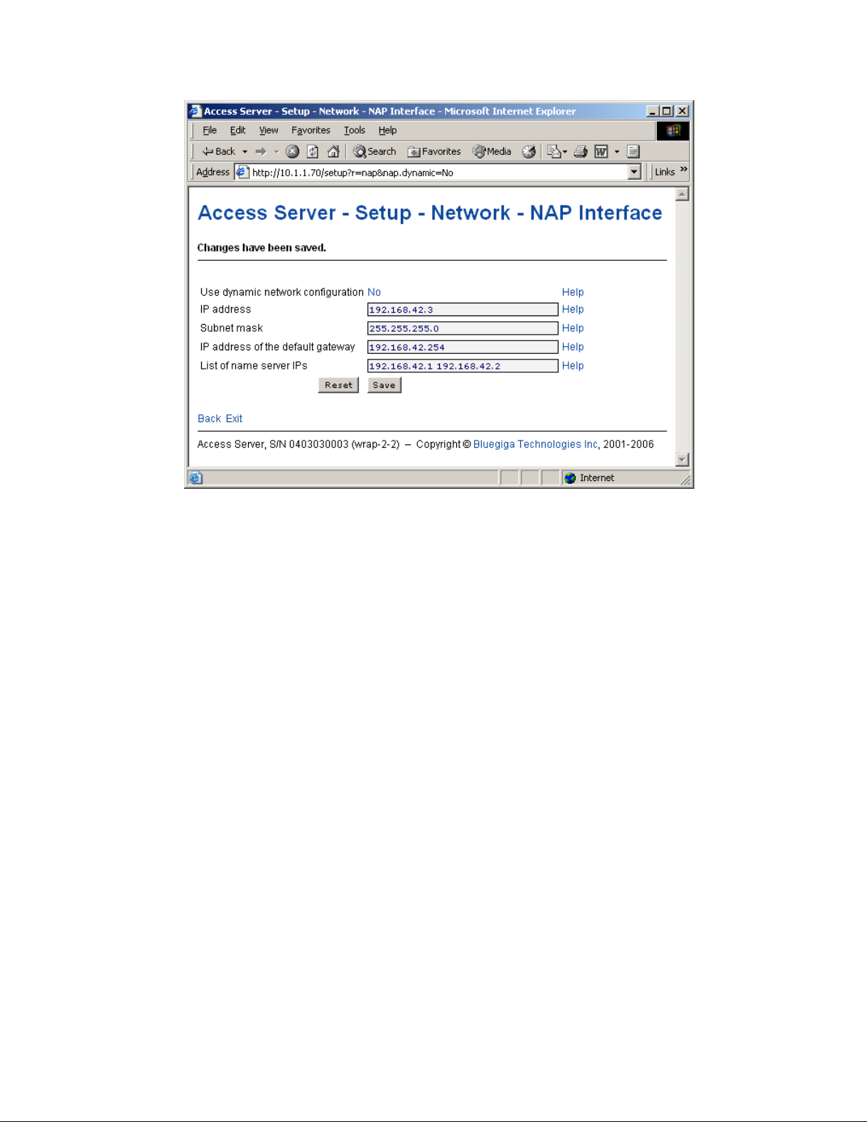
• Toggling Yes/No and on/off links
Clicking the Yes/No link (see Figure 2-12) immediately changes the setting and saves the
change. Typically these links are used display or hide further settings.
13
Page 22
Chapter 2. Getting Started with Access Server
Figure 2-12. Yes / No links in WWW Setup
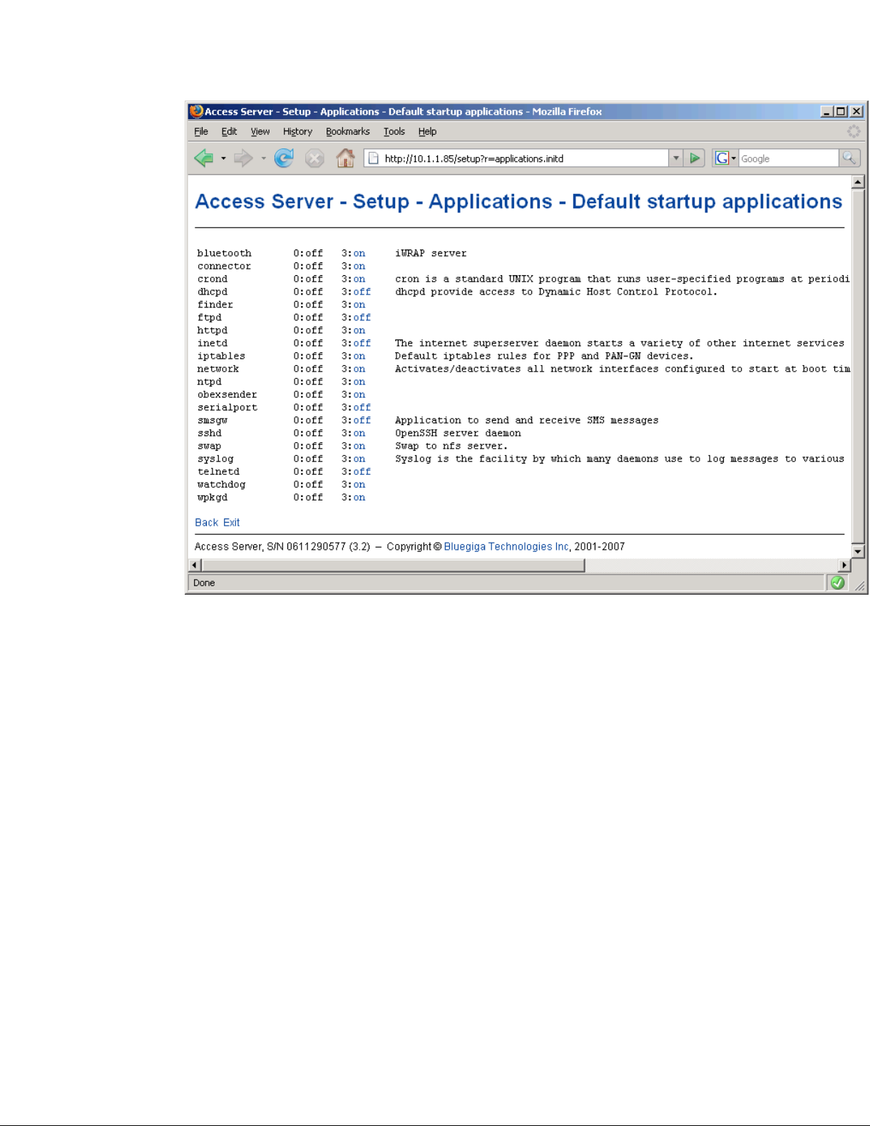
The on/off links in Setup −→ Applications −→ Default startup applications behave in a same
way, making and saving the change immediately (see Figure 2-13).
14
Page 23
Chapter 2. Getting Started with Access Server
Figure 2-13. Selecting Default startup applications in WWW Setup
Note: To configure the default startup applications from the command line, use the chkconfig
command.
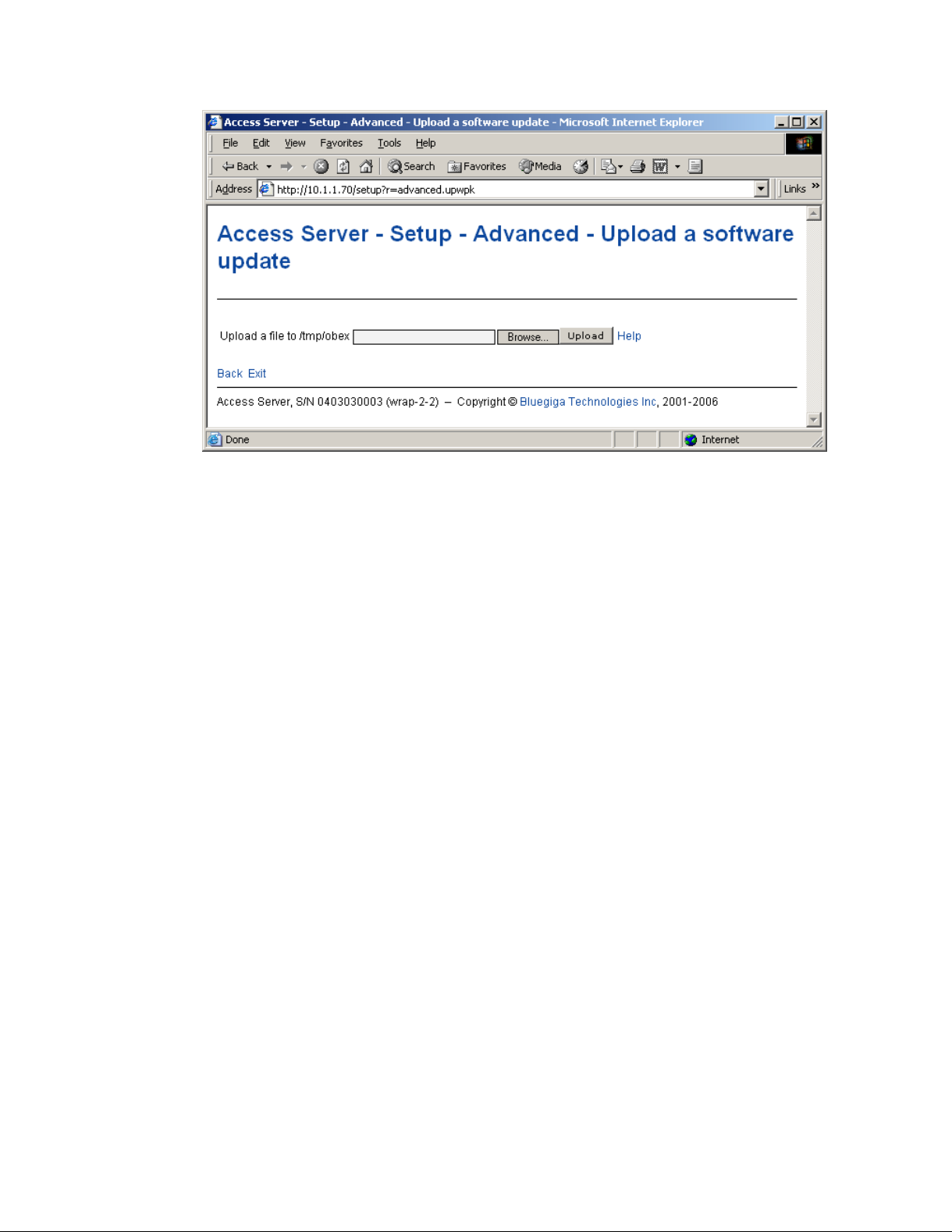
• Upload links
The WWW Setup has settings that allow user to upload files to Access Server, for example
Setup −→ Advanced −→ Upload a software update (see Figure 2-14).
15
Page 24
Chapter 2. Getting Started with Access Server
Figure 2-14. Uploading files via WWW Setup
Use the Browse... button to select the file to be uploaded, and send it to Access Server by
clicking Upload.
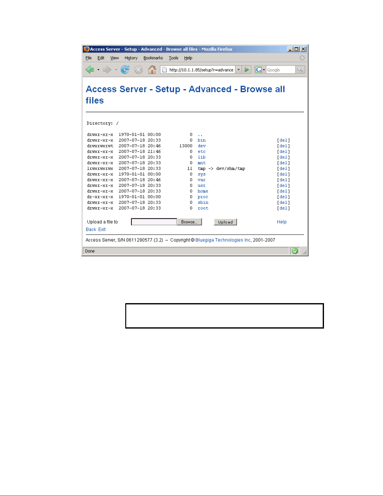
• Browsing files
Some WWW Setup pages allow users to browse the Access Server file system or part of it,
such as Setup −→ Advanced settings −→ Browse all files (see Figure 2-15).
16
Page 25
Chapter 2. Getting Started with Access Server
Figure 2-15. Browsing files via WWW Setup
Click the directory names to navigate in the file system.
Click a file name to view its contents.
Click del to delete a file or an empty directory.
Warning
Deletion is not confirmed.
The WWW Setup also has menu items that run commands in Access Server, and show the output
in the browser window. Some commands, such as rebooting Access Server, are confirmed before
execution.
2.6. Using the setup Command Line Application
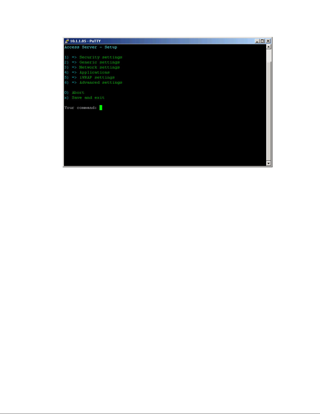
The basic configuration settings can also be changed by using the setup application at the command line interface.
The setup application displays the settings in a hierarchical menu (see Figure 2-16). Navigating
the menu is accomplished by entering the number or letter corresponding to the setting to be
viewed and/or changed and pressing Enter. Pressing only Enter either accepts the previous
value of the setting or returns to the previous level in the menu hierarchy.
17
Page 26
Chapter 2. Getting Started with Access Server
Figure 2-16. Using the setup Command Line Application
Note: Ensure that your terminal application does not send line ends with line feeds. If your terminal
sends both CR and LF when you press Enter, you cannot navigate in the setup application.
2.7. Resetting a Configuration
You can reset the default configuration with the setup -r command. The command requires
rebooting of Access Server. When the system starts up, the default configuration settings are restored. If you have only changed the configuration by using the setup application, the following
commands at the Access Server ’s command prompt will suffice:
[root@wrap /]$ setup -r
[root@wrap /]$ reboot
Note: This does not reset the edited files to factory defaults; it only affects only the settings changed
through the WWW Setup or the setup command line application.
2.8. Exporting and Importing Configurations
You can export configuration settings (expect for passwords and the list of default startup applications) with the following command:
[root@wrap /root]$ setup -o > settings.txt
The saved settings can later be restored with the following commands:
[root@wrap /root]$ setup -m settings.txt
[root@wrap /root]$ reboot
18
Page 27

Chapter 3. Using the System
This chapter describes the basic features of a Bluegiga Access Server. This includes information
on using Access Server as a Bluetooth LAN/PAN Access Point or a Bluetooth Serial Port Cable
Replacer, using the Web Server, ObexSender, and WRAP Package Management System. The
various ways of uploading content for browsing and/or downloading are also included, as well
as getting familiar with the utility applications.
Using the features described in this chapter does not require Access Server Software Development Kit to be installed.
Note: The default username is root and the default password is buffy.
Note: Most of the configuration files are in Linux text file format, where the lines end with a sin-
gle Line Feed (LF, "\n") character. Some applications will not work if the configuration file format is
changed to MS-DOS format (this happens, for example, if you transfer the files to Windows for editing with Notepad), where the lines end with both Carriage Return and Line Feed (CR+LF, "\r\n")
characters.
3.1. Network Interfaces
The Access Server network interfaces are described in Table 3-1.
Interface Description
nap Dynamic virtual Ethernet ("cable") device. This is the device having an IP
address. All the programs should use this device instead of eth0.
eth0 Real Ethernet device, which is dynamically linked to the nap device. Do not
use this device, use nap instead.
wlan0 Wi-Fi device. In the client mode (default), this device has its own IP address.
In the access point mode, it is dynamically linked to the nap device (the
default interface).
wifi0 Virtual control device for wlan0. Do not use this device.
gn Virtual device for PAN-GN connections.
bnep# These devices are used for incoming and outgoing PAN connections. These
devices are created, deleted and linked (to nap or gn) dynamically.
ppp# These devices are used for incoming and outgoing LAP connections. These
devices are created and deleted dynamically. By default, data coming from
ppp# is masqueraded to the nap device.
Table 3-1. Access Server Network Interfaces
3.2. Bluetooth
The iWRAP servers (one server in Access Server 2291, three in Access Server 2293) are automatically started at power-up. By default, the Object Push and File Transfer Profiles are activated.
The iWRAP servers can be accessed and controlled (by applications or even interactively with a
telnet client) through the iWRAP interface, described in Chapter 7. Currently, there can be up to
14 simultaneous Bluetooth connections between a single master iWRAP server and up to seven
simultaneous slaves.
19
Page 28
Chapter 3. Using the System
3.2.1. iWRAP Password Protection
The access to iWRAP can be password protected. The default password is buffy, but it can be
set off or changed with the setup application (see Section 2.4). The password is case sensitive.
The password must be typed in as the first command after the server has replied with "READY."
3.2.2. LAN Access Profile
This profile is not automatically started at boot. The default settings can be changed with the
setup application (see section Section 2.4), or runtime with the iWRAP interface (see Chapter 7).
Access Server can also act as a LAN Access Client, but in this case it must be controlled manually
using iWRAP commands, as described in Chapter 7.
Note: Since Bluetooth specification 1.2, LAN Access Profile has been deprecated.
3.2.3. Serial Port Profile
This profile is not automatically started at boot. The default settings can be changed with the
setup application (see section Section 2.4).
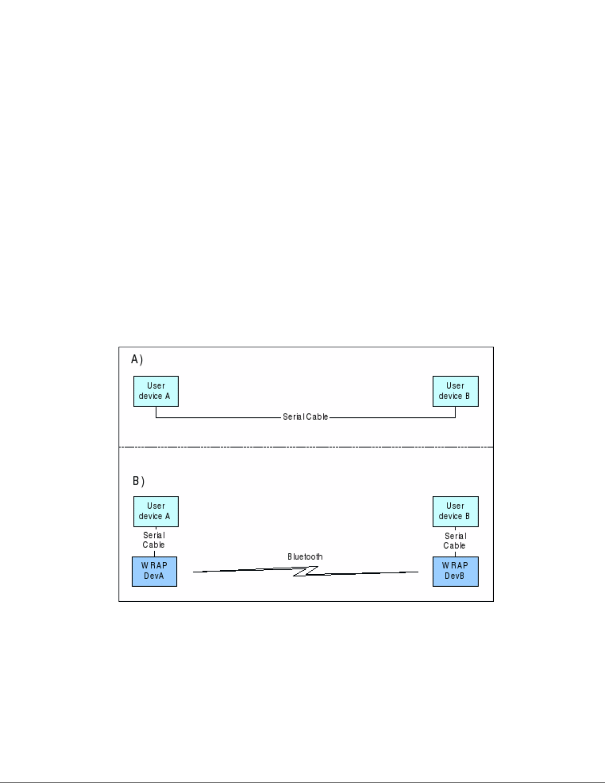
The Serial Port Profile is used to replace an RS-232 serial cable between two devices with a
Bluetooth connection. The physical setup is shown in Figure 3-1.
Figure 3-1. Serial Cable Replacement Physical Setup
State A) in the figure is the starting situation with a serial cable connecting the devices. This
cable is to be replaced with a Bluetooth connection.
In state B) the long serial connection is replaced with a Bluetooth Serial Port Profile connection
between the two Access Server devices. These Access Server devices are then locally connected
20
Page 29

Chapter 3. Using the System
to the user devices with (short) serial cables. The cable between user device A and Access Server
device A must be a cross-over cable. The cable between user device B and Access Server device
B must be similar (direct or cross-over) to the one used in state A).
If RTS/CTS handshaking is used to ensure correct data transfer, the serial cables must have these
pins connected. Notice that this handshaking is "local": it takes place between the user device
and Access Server. No handshaking between user device A and user device B on the other end
of the Bluetooth connection is provided.
If RTS/CTS handshaking is not used, CTS must be connected to DTR.
DCD, DTR, and DSR signals are not supported. This also means that user devices A and B will
not be able to tell whether or not the Bluetooth connection is up.
When the physical setup is ready, you can create the Bluetooth connection. By default, the Serial
Port Profile is started up at boot with the default settings. That is, listening in DevB mode, at
115200 bps, 8 data bits, no parity, 1 stop bit, and RTS/CTS enabled. To change these settings, use
the setup application or the WWW Setup interface, as described in Section 2.4.
Note: To enable Serial Port Profile, navigate to Setup −→ Applications −→ Default startup applica-
tions in the WWW Setup interface, and switch serialport application to off.
Enabling can also be done from command prompt with command chkconfig serialport on.
3.2.4. Object Push and File Transfer Profile
Access Server has two OBEX profiles, Object Push Profile (ObjP) and File Transfer Profile (FTP).
You can use these profiles to transfer files between different Access Servers and other devices
supporting ObjP or FTP.
3.2.4.1. Incoming ObjP and FTP
Incoming ObjP and FTP connections are handled by forwarding the call to obexserver program,
which handles both profiles. By default the working directory is /tmp/obex. FTP users have full
read and write access to that directory. When Access Server starts up, the default contact card is
copied from /etc/default.vcf to that directory.
In ObjP mode, obexserver will prefix received files with sender’s Bluetooth address and iWRAP
port number. In case of a duplicate filename, a counter is also appended to filename.
The --fork parameter in obexserver understands following meta characters:
Meta Description
$$ Character ’$’
$r Configured root directory
$p Configured prefix
$b Remote’s Bluetooth address
$t Temporary file name, with directory
$T Real file name, without prefix and directory
$f Real file name, with prefix and directory
$F Real file name, with prefix, but without directory
21
Page 30

Chapter 3. Using the System
Meta Description
$d
Current UNIX timestamp
Table 3-2. obexserver’s metas
If the --fork’ed program returns non-zero errorlevel, the received file will be deleted.
3.2.4.2. Outgoing ObjP and FTP
Three simple utilities, obexput, obexget and obexsender-put are provided. They can be used to
send and retrieve files to and from another Bluetooth device using ObjP or FTP.
Usage:
obexput [parameters] bdaddr channel file(s)
obexget [parameters] bdaddr channel file(s)
obexsender-put parameters
Enter any of these commands without parameters to get a short help for using the command.
Note: You can use friendly name instead of Bluetooth address as the "bdaddr" parameter and keyword "OBJP" or "FTP" as the "channel" parameter for automatic device and service discovery.
For obexput and obexget, a non-zero return value indicates an error. The reason for this error is
printed to standard output.
Tip: You can use obexput easily from iWRAP (see Chapter 7) with following syntax:
CALL bdaddr OBJP FORK \"/usr/bin/obexput - 1 filename\"
Value - as bdaddr and 1 as channel tells obexput that it is launched by the iWRAP server, and that
data connection is bound to standard input and output.
Originally obexsender-put was a helper application for ObexSender. It can also be used by other
programs. It calls the given Bluetooth device, calculates a device hash value and then sends one
or more files to it using ObjP. obexsender-put takes following parameters:
Parameter Description
--configfile name Use "name" as config file.
--bdaddr bd Call to "bd" and send files specified in config
file.
--iwraphostname host
Use iWRAP in host. Defaults to "localhost".
--iwrapport port Use iWRAP in port. Defaults to "10101".
--iwrappassword pass Use iWRAP password. Defaults to empty.
--verbose level Specify debug verbosity level. Defaults to "0".
Logging is written to standard output.
--hash bd Calculate and show hash value by calling to
"bd", don’t send anything.
22
Page 31

Chapter 3. Using the System
Parameter Description
--uuid uuids
Use specified UUIDs. Defaults to
"OBEXOBJECTPUSH,OBEXFILETRANSFER".
Table 3-3. Parameters for obexsender-put
Config file specifies filenames and hash values for them. First there has to be one or more "regex"
lines, followed by one or more "file" or "exec" lines, followed by an empty line. There can be
multiple instances of these tuples. Syntax is:
regex <match1>
regex <match2>
file <fakename1> </path/to/file1>
file <fakename2> </path/to/file2>
exec </path/to/command1>
exec </path/to/command2>
regex <match3>
file <fakename3> </path/to/file3>
...
Parameter "match" is a regex of hash. If it matches calculated hash, the file(s) in this tuple will
be sent. See lottery example in SDK for more information about exec.
Example of config file:
regex Nokia.9500
file hello.jpg /mnt/usb/communicator.jpg
regex .
file hello.jpg /mnt/usb/unknown.jpg
The return value is:
Value Description
0 OK, files sent without errors.
1 Error in parameters.
2 Fatal error. Reboot!
3 No files sent. Operation should be retried.
4 No files sent. Remote refused to received, do not retry.
5 OK, no files matched the hash, nothing sent.
6 Error, file not found from disk.
7 Error, remote device does not support specified UUID(s).
Table 3-4. Errorlevels from obexsender-put
There is also another ObexSender helper application called obexsender-inquiry. It can be used
to inquiry for nearby Bluetooth devices. It’s usage and return values are similar to obexsender-
23
Page 32

Chapter 3. Using the System
put command. All results are written to standard output.
Usage:
obexsender-inquiry parameters
Parameter Description
--pair-only List all paired devices and exit.
--inquiry Inquiry and exit.
--ready-check Check if iWRAP is ready or not.
--iwraphostname host Use iWRAP in host. Defaults to "localhost".
--iwrapport port Use iWRAP in port. Defaults to "10101".
--iwrappassword pass Use iWRAP password. Defaults to empty.
--verbose level Specify debug verbosity level. Defaults to "0".
Logging is written to standard output.
Table 3-5. Parameters for obexsender-inquiry
Value Description
0 OK.
1 Error in parameters.
2 Fatal error. Reboot!
Table 3-6. Errorlevels from obexsender-inquiry
3.2.5. PAN Profiles
Access Server has support for all PAN profile modes: Personal Area Network User (PANU), Network Access Point (NAP) and Generic Networking (GN). Accepting incoming PAN connections
to any of these modes is disabled by default for security reasons.
Access Server can be configured to accept incoming PAN connections and the default settings
can be changed by using the setup application (see section Section 2.4).
The Network Access Point mode is the most useful PAN profile mode. You can enable it by
sending the enable-pan.wpk file (available on-line at http://bluegiga.com/as/current/enablepan.wpk) to Access Server by using the Bluetooth Object Push profile. Alternatively, you can
copy the file to the root of a USB memory dongle and insert the dongle to Access Server ’s USB
port.
The device creating the PAN connection decides upon the modes to be used. Access Server
automatically handles incoming connections. Access Server can also act as a PAN client, but in
this case it must be controlled manually by using the iWRAP interface, described in Chapter 7.
3.2.6. Changing the Bluetooth Range
The transmit power of Access Server is configurable. By default, class 1 (100 meter range) settings are used. The settings can be changed down to "class 2" (10 meter range) settings with the
btclass 2 command, or even lower with the btclass 3 command. Class 1 settings can be restored
with the btclass 1 command. You can find these command also in Setup −→ Advanced settings
−→ Bluetooth commands menu in the WWW Setup interface.
24
Page 33

Chapter 3. Using the System
After btclass # is given, it is recommended to reboot Access Server once to restart ObexSender
and other applications connected to the iWRAP server(s).
Note: It is recommended to stop all applications using Bluetooth before issuing btclass command.
3.2.7. btcli
You can send iWRAP commands from the command line by using the btcli application. See
Section 7.4 for more information.
3.2.8. serialbluetooth
It is also possible to control the first iWRAP server (at port 10101) through RS-232 with the
serialbluetooth application.
Usage:
serialbluetooth [options]
To see the command options, enter the serialbluetooth --help command.
Basically, serialbluetooth takes commands from a serial port and forwards them to the iWRAP
server. All the commands available through iWRAP are also available through serial port.
There are two exceptions:
1. After making an outgoing RFCOMM data call, all input from the serial port is forwarded
to the data socket, not to the control socket. To close the data socket, you have to write
+++ with a 200ms pause before each character. It is not possible to have two concurrent
RFCOMM calls.
2. All incoming RFCOMM calls are answered automatically. Again, to close the data socket,
write +++ as with the outgoing call.
3.3. Compact Flash Cards
Access Server functionality can be extended by using GSM/GPRS, Wi-Fi and GPS Compact
Flash cards. The supported Compact Flash cards are listed in Appendix D.
3.3.1. Compact Flash GPRS Cards
The operating system automatically identifies the Compact Flash GPRS card when it is inserted.
Access Server can use the GPRS card to connect to the GPRS network, or to act as an SMS
gateway to send and receive SMS messages.
You can enable the GPRS mode and configure its settings, such as the SIM card’s PIN code, by
using the setup application or its WWW interface. For more information, see Section 2.4 and
documentation for Setup −→ Network settings −→ Enable GPRS interface in Appendix B.
GPRS, when enabled, is by default only turned on when needed. If Access Server can access the
Internet (or any desired address) by using the default interface nap, it does not activate and use
the GPRS (ppp0) interface.
The simplest way to test the GPRS interface is to configure the default interface nap to use
dynamic network configuration (the default) and enable GPRS through the setup application,
25
Page 34

Chapter 3. Using the System
then to disconnect the Ethernet cable, reboot the device with the management console enabled.
After the boot, ping an IP address in the Internet, such as 194.100.31.45 (bluegiga.com).
The first five or so packets are lost, but after that the GPRS connection should be up. To enable
the interface automatically, just enter ping -c 20 ip-in-internet to /etc/rc.d/rc.local.
Note: If you also want to use the Ethernet connection, you must remove it from the default interface (nap) bridge and configure its network settings individually using the setup application while
keeping the default interface network settings in their default (dynamic) state.
Using WRAP SMS Gateway Server is documented in Section 3.5.3.
If needed for some special use, the Compact Flash GPRS card can also be accessed directly from
/dev/ttyS0, a device file which exists if the GPRS card is successfully initialized.
3.3.2. Compact Flash GPS Card
The operating system automatically identifies the Compact Flash GPS card when it is inserted.
At that time, the device file /dev/ttyS0 is created and the GPS card can be accessed by using
that device with the serial port settings the GPS card uses.
The supported Compact Flash cards are listed in
Appendix D.
3.3.3. Compact Flash Wi-Fi Cards
Access Server supports Prism II/III based CF Wi-Fi cards. The supported Compact Flash cards
are listed in
By default, Access Server notices when a supported Wi-Fi card is inserted and tries to use it in
the client mode, without encryption. So, if there is an open Wi-Fi Access Point in range, Access
Server will automatically connect to it.
To configure Wi-Fi to the Access Point mode, or to change other Wi-Fi settings, use the setup
application or its WWW interface at Setup −→ Network settings −→ Wi-Fi.
Note: Older Compact Flash cards with firmware version 1.4.2 do not work in the Access Point mode.
Instead, you will see an error message in the system log (/var/log/messages, viewable at Setup −→
Advanced −→ System Information −→ Show system log file).
A standard set of command line wireless utilities is provided to fine-tune your Wi-Fi configuration:
• iwconfig
• iwlist
• iwpriv
For more information on these utilities, see: http://www.hpl.hp.com/personal/Jean_Tourrilhes/Linux/Tools.html
Appendix D.
3.4. USB Memory Dongles and Compact Flash Memory Cards
Access Server’s persistent memory storage can be extended by using an USB memory dongle or
a Compact Flash memory card. These are also used by the Access Server Remote Management
System (see
mounted, and scanned for management packets, which are processed and unmounted.
Section 3.5.5) - each time a dongle or memory card is inserted, it is automatically
26
Page 35

Chapter 3. Using the System
To use the USB dongle or Compact Flash memory card for your own applications, the memory
must be mounted manually by using command:
[root@wrap /]$ mount -t vfat device /mnt/usb
The device parameter is a path to the USB dongle or Compact Flash memory card filesystem
device. For the first dongle inserted after a reboot, it is /dev/sda1 if the dongle is partitioned
(which often is the case), or /dev/sda if the dongle has no partition table. The first Compact
Flash memory card is typically at /dev/hda1, correspondingly. If you have used several dongles
after reboot, new device file names are created: /dev/sdb1 for the second one, /dev/sdc1 for
the third one, and so on. In the case of memory cards, naming is similar, that is, the second one
gets device file name /dev/hdb1.
Note: Always remember to unmount the memory dongle or memory card with command:
[root@wrap /]$ umount /mnt/usb
The filesystem in USB dongle can get corrupted if you have a power failure while you are writing
data to it. Utility called fsck.vfat is included to fix the problem. There’s no harm running it on a
clean filesystem. If you are using init scripts (/etc/rc.d/rc.local) to automatically mount the
USB dongle on boot time, it is recommended to run fsck.vfat before mounting.
[root@wrap /]$ fsck.vfat -a device
[root@wrap /]$ mount -t vfat device /mnt/usb
3.5. Servers
Access Server server applications are started automatically at system power-up or when an
iWRAP server or the Internet services daemon needs them. The servers and their purposes are
described in
Server Description
bluetooth Access Server iWRAP Server, which is described in detail in Chapter 7.
connector Access Server Connector, service which automatically opens and
finder WRAP Finder Service.
obexsender WRAP ObexSender server.
smsgw WRAP SMS gateway server, which is described in detail in Section
watchdog WRAP user level watchdog.
wpkgd WRAP remote management system daemon.
crond A daemon to execute scheduled commands. This server is configurable
Table 3-7.
maintains connections to specified Bluetooth devices. Configurable
using the setup application and its WWW interface.
3.5.3
. Notice that this server is disabled by default. Use the setup
application or the chkconfig smsgw on command to enable it.
through the /var/spool/cron/crontabs/root file or the crontab
command in the same way as any Linux crond.
27
Page 36

Chapter 3. Using the System
Server Description
ftpd
Internet File Transfer Protocol Server. You can configure this server
with the setup application. Notice that this server is disabled by
default. Use the WWW interface of the setup application or the
chkconfig ftpd on command to enable it.
udhcpd This server is a DHCP daemon for providing automatic network
configuration for clients in the network. Notice that, by default, this
server is only enabled for the gn interface, used by Bluetooth PAN
Generic Networking profile.
udhcpcd DHCP client daemon for automatic network configuration.
inetd Internet services daemon. Notice that this server is disabled by default.
Use the setup application or the chkconfig inetd on command to
enable it.
httpd Web server, which is described in detail in Section 3.5.7.
pppd Point to Point Protocol daemon. iWRAP server uses this server. This
server can be used manually over the user serial port (/dev/ttyAT1).
snmpd SNMP daemon. This server is available as a separate installation
packet.
sshd SSH daemon.
syslogd System logging daemon. This server can be configured by using the
setup application.
telnetd Telnet protocol server. Notice that this server is disabled by default.
Use the setup application or the chkconfig telnetd on command to
enable it.
zcip Zero configuration networking service.
ntpd Network Time Protocol (NTP) daemon.
Table 3-7. Access Server Servers
3.5.1. Finder
The Finder service is a small service, which listens for UDP broadcast queries from Access Server
Finder applications and responses to those queries with identification information (IP address,
model, serial number, etc.) about Access Server.
The finder command can be used to query Finder service information from Access Servers in the
network. With no parameters, finder sends the query using the broadcast address of the default
interface (nap). Broadcasting to networks of other interfaces can be done with --interface
parameter, such as the zero configuration interface nap:9in the following example:
[root@wrap root]$ finder --interface nap:9
Access Server 2291 (S/N: 0402110112) (build: 3.1)
- Hostname: wrap.localdomain
- IP: 169.254.30.233 (nap:9), 192.168.161.1 (gn)
- Ethernet MAC: 00:07:80:00:03:ed
- iWRAP: 10101 00:07:80:80:0b:c3 bt1.2 (W0402110112_1)
Access Server 2291 (S/N: 0606221029) (build: 3.1)
28
Page 37

Chapter 3. Using the System
- Hostname: wrap.localdomain
- IP: 169.254.36.138 (nap:9), 192.168.161.1 (gn)
- Ethernet MAC: 00:07:80:00:0d:44
- iWRAP: 10101 00:07:80:80:0b:c4 bt1.2 (W0606221029_1)
[root@wrap root]$
With parameter --send finder will send info once to a specified host, for example to inform that
device has booted.
For information about the finder protocol, see Chapter 9.
3.5.2. ObexSender
The ObexSender application is automatically started in Access Server. Its purpose is to receive
business cards (vCards), images, or other files, and analyze their content and send files back
selecting them based on configured keywords found.
ObexSender can also make an
inquiry for bluetooth devices, and automatically send one or more
files to all new devices found.
ObexSender can be configured with the setup application or by editing the
/etc/obexsender.conf file (see Section 2.4).
For detailed instructions on using ObexSender, see Chapter 5.
3.5.3. SMS Gateway Server
WRAP SMS Gateway Server supports Nokia 20, Nokia 30, or Wavecom WMOD2 compatible
GSM terminals and the supported GSM/GPRS Compact Flash cards for sending and receiving
SMS messages. By default, the Compact Flash card is used. The PIN code query of the SIM card
at power-up must be disabled.
WRAP SMS Gateway Server is disabled by default. To enable it, use the setup application’s
WWW interface, as described in section Section 2.4. Enabling is done at Setup −→ Applications
−→ Default startup applications −→ smsgw.
WRAP SMS Gateway Server can be configured to use a modem connected to the user serial
port with the setup application or its WWW interface by changing the setting at Setup −→
Applications −→ SMS gateway settings −→ Modem device to /dev/ttyAT1 from the default
/dev/ttyS0.
Note: If you are using the user serial port, ensure you have Bluetooth Serial Port Profile disabled, as
they share the same physical user serial port.
Note: To use Nokia terminals, the device must be connected to the user serial port when the server
starts up. Also, the terminal must be configured to operate in RS-232/AT command. Nokia terminals
are configured with the N20 or N30 Configurator application.
For further information on using smsgw, see the makesms example in
Section 6.3.1.
29
Page 38

Chapter 3. Using the System
3.5.4. User Level Watchdog
WRAP User Level Watchdog daemon listens on UDP port 4266 for "id timeout" messages. "id"
is an ASCII string, without spaces. If "timeout" equals to 0 (zero), the "id" is removed from the
list of processes to wait. If "timeout" is greater than 0 (zero), the "id" is added or updated.
When there is no message for "id" received within the "timeout" seconds, the user level watchdog dies and the kernel watchdog reboots Access Server.
The watchdog command can be used to send messages to the watchdog daemon. This is done
through command watchdog id timeout. For example, watchdog test 5.
3.5.5. Remote Management
Access Server contains simple tools that provide means for full and secure remote management
of the device.
The basic remote management can be performed using the WWW Setup interface, SSH command line access, and SCP and SFTP file transfer protocols.
In addition to those, Access Server contains WRAP Remote Management System for transferring
management packets over different media to Access Server and automatically sending response
packets back.
The management packets (
autoinstall directory in Access Server (/tmp/obex by default, but configurable with the setup
application or WWW interface at Setup −→ Applications −→ wpkgd settings). The easiest way
to transfer a management packet to this directory is to upload it from WWW Setup at Setup −→
Advanced settings −→ Upload a software update.
.wpk) are automatically processed when they are transferred to the
*
3.5.5.1. Overview
A management action is performed using the following procedure:
1. A customer system prepares the management packet (*.wpk).
2. The management packet is delivered to Access Server, to the packaging daemon’s directory.
You can currently use Bluetooth, SCP, SFTP and plain FTP to do this. The packet can also
be transmitted using a USB memory dongle, Compact Flash memory card or through the
WWW Setup interface.
3. The Access Server packaging daemon processes the management packet, possibly generating a reply packet.
4. (Optional) The reply packet is delivered to the customer system.
3.5.5.2. Management Packet Format
• The package name must be of format name.wpk, where "name" can be user defined.
• Package must be a tar archive that is compressed with gzip (such as files named *.tar.gz or
*.tgz).
30
Page 39

Chapter 3. Using the System
• The package must contain a package information file called wpkg.pif in the package root (the
file contents are described later), otherwise the built-in defaults for wpkg.pif are used.
• All other files, if any exist, should be data files, scripts or executables required for the man-
agement operation.
3.5.5.3. Management Packet Information File Format
The management packet information file (wpkg.pif) consists of tags and their data, described
here:
%wpkg-version: 2
Contains information for version checking. 2 is currently the only supported version. It is also
the default value.
%wpkg-prepare: [command line[s]]
One or more commands (all commands are lines until the next tag is interpreted as a command
line) to execute. Commands may contain parameters, redirections and job control as well.
The built-in default value for this is /usr/bin/dpkg -i *.deb || echo ERROR: Installation failed..
This enables the special case of creating .wpk packets from .deb packets simply with tar czf
foo.wpk foo.deb. (wpkg.pif is not needed in this special case).
%wpkg-reply: method
This value indicates where the generated reply packet is sent. By default, it is sent to where it
came from. Possible values are:
• default
• file:///path/filename
• scp://remote:file
• objp://bdaddr/
• none
%wpkg-format: type
This value indicates what kind of a reply packet will be generated. Possible values are:
• ascii (this is the default value, everything echoed by the prepare-section will be sent).
• tgz (all files in the current directory will be sent).
• vcf (same as ascii, but assume it is a vCard).
• vmg (same as ascii, but assume it is a vMessage).
• vnt (same as ascii, but assume it is a vNote).
• vcs (same as ascii, but assume it is a vCalendar).
• html (same as ascii, but assume it is HTML).
%wpkg-auth: auth
Optional authentication string required by wpkgd.
31
Page 40

Chapter 3. Using the System
3.5.5.4. Management Operation Example: Hello World
See below for the simplest example of wpkg.pif:
%wpkg-version: 2
%wpkg-prepare:
echo Hello world
This will generate a reply packet containing text "Hello world". You can generate the wpk file
simply by giving the command tar czf hello.wpk wpkg.pif.
3.5.5.5. Management Operation Example: Software Update
See below for a more complex example of wpkg.pif:
%wpkg-version: 2
%wpkg-prepare:
FOO=‘pwd‘
cd /
tar xzf ${FOO}/files.tar.gz
echo Done.
This example will extract files from the included files.tar.gz file. You can generate the wpk
file with command tar czf update.wpk wpkg.pif files.tar.gz.
3.5.5.6. Management Operation Example: IPQUERY
In this example, we build a simple packet that can be used with a Bluetooth enabled phone to
retrieve the IP address of an Access Server. File wpkg.pif reads:
%wpkg-version: 2
%wpkg-format: vcf
%wpkg-prepare:
ipaddr() {
echo ‘ifconfig nap | grep "inet addr" | awk -F [:] \
\\{print\\$2\\} | awk \\{print\\$1\\}‘
}
serialno() {
echo ‘wrapid | grep Hardware | awk \\{print\\$5\\}‘
}
echo -e "BEGIN:VCARD\r"
echo -e "VERSION:2.1\r"
echo -e "N:‘serialno‘\r"
echo -e "TEL:‘ipaddr‘\r"
echo -e "URL:‘hostname‘\r"
echo -e "END:VCARD\r"
This example will send the reply back as a vCard (contact card). Please note that you have to
include all required vCard formatting by yourself. You can generate the wpk file simply giving
the command tar czf ipquery.wpk wpkg.pif.
32
Page 41

Chapter 3. Using the System
To use this example, send the file ipquery.wpk to the inbox of your Bluetooth phone. Check
that you have Bluetooth enabled in the phone. Then, from the phone’s inbox, send the file
ipquery.wpk over Bluetooth to Access Server.
3.5.5.7. Management Operation Example: Beep
See below for beep example of wpkg.pif:
%wpkg-version: 2
%wpkg-reply: none
%wpkg-prepare:
echo A > /dev/led
sleep 1
echo a > /dev/led
3.5.5.8. Management with USB Memory Dongle or Compact Flash Memory Card
When an USB memory dongle or Compact Flash memory card is inserted, Access Server automatically tries to mount it using VFAT filesystem. If the mount is successful, Access Server scans
the root directory for
mon processes it. Optional reply packets are saved back to the root directory (unless otherwise
stated in the %wpkg-reply tag).
.wpk files. If one is found, the WRAP Remote Management System dae-
*
3.5.5.9. Listing and Uninstalling Software Component
To list installed software components use command wpkgd -l. To uninstall an installed component use wpkgd -e [component]. See wpkgd command without parameters for more information.
3.5.6. FTP
If you enable the FTP server, users can use it to log in anonymously to the /tmp/obex directory
with download access or as root with password buffy to the root directory with full access.
The password and other settings can be changed on Access Server with the setup application or
by editing the /etc/ftpd.conf file (see Section 2.4).
Note: Do not enable FTP because it is insecure. Use SSH (SCP or SFTP) instead. A commonly used
client with a graphical user interface is, for example, WinSCP (http://winscp.net/).
3.5.7. Web Server
The integrated web server in Access Server supports HTTP/1.0 methods GET and POST, and
has light user authentication capabilities. The content can be either static or dynamic - the WWW
server is CGI/1.1 compatible.
The web server is always running and the content (http://wrap-ip-address/) is located in the
/var/www/html/ directory in Access Server’s file system.
The web server is configured to protect the WWW Setup interface with a username and password. The default username and password can be changed as instructed in Section 2.4. For further information about using the web server for your own applications, see the web examples
in Section 6.3.1.
33
Page 42

Chapter 3. Using the System
3.5.8. SNMP
A separate software update package is available from Bluegiga Techforum
(http://www.bluegiga.com/techforum/). This update adds the Net-SNMP suite of
applications to Access Server. The current Net-SNMP implementation for Access Server is
limited and will be extended in the future. However, it can be used to poll the basic status of
Access Server.
Configuration details can be found and altered in configuration file /etc/snmp/snmpd.conf,
which is accessible as described in Section 2.4.
For more information about the Net-SNMP suite, see http://net-snmp.sourceforge.net/
3.5.9. OpenVPN
A separate software update package is available from Bluegiga Techforum
(http://www.bluegiga.com/techforum/). This update adds the OpenVPN™, a full-featured
SSL VPN solution, to Access Server.
For detailed instructions on using OpenVPN with Access Server, see Section 10.4.
For more information about the OpenVPN™, see http://openvpn.net/.
3.5.10. SSH
By default, users can use SSH to log in (or SCP and SFTP to transfer files) as user root with
password buffy. The password can be changed on Access Server by using command passwd
or with the setup application.
3.5.11. Telnet
If you enable telnet, users can log in over telnet as user root with password buffy. The password can be changed on Access Server using the command passwd or with the setup application.
3.5.12. NTP
The ntpd service uses the standard Network Time Protocol (NTP) to keep Access Server system
time automatically in sync using a random selection of eight public stratum 2 (NTP secondary)
time servers. The service is also configured to answer NTP requests from other devices.
The NTP server configuration can be altered by editing its configuration file /etc/ntpd.conf.
3.6. Utilities
Access Server is basically a small Linux system. Whether logged in from the management console or with SSH, your shell session starts as the root user in the root directory. After that, you
have the option to use most of the standard Linux utilities, briefly listed and described in Table
3-8
. Most of the commands have a small built-in usage help that can be seen by executing the
command with the -h or --help parameter.
Note: Do not enable telnet because it is insecure. Use SSH instead.
34
Page 43

Chapter 3. Using the System
Application Description
adduser
This command add user to the system.
arping This command pings hosts by ARP requests/replies.
awk Pattern scanning and processing language.
btclass WRAP baseband module control script (sets basebands power
class).
basename Strip directory and suffix from file names.
bash Bourne-Again SHell.
btcli WRAP iWRAP Server Command Line Interface utility.
btproxy WRAP iWRAP Proxy for Access Servers (test revision).
bunzip2 Decompress bzip2-compressed files.
bzcat Decompress bzip2-compressed files to stdout.
cardctl Monitor and control the state of PCMCIA sockets.
cat Concatenate files and print on the standard output.
chat Automated conversational script with a modem.
chgrp Change group ownership.
chkconfig Updates and queries runlevel information for system services.
chmod Change file access permissions.
chown Change file owner and group.
chroot Run command or interactive shell with special root directory.
clear Clear the terminal screen.
cmp Compare two files.
cp Copy files and directories.
cpio Copy files to and from archives.
crontab Maintain crontab files for individual users.
cut Remove sections from each line of files.
date Print or set the system date and time. Notice that the date command
does not store the date into the battery powered real time clock. Use
the hwclock application instead.
dd Convert and copy a file.
deluser Delete a user from the system.
df Report file system disk space usage.
dfu WRAP baseband module firmware upgrade tool.
dialup WRAP iWRAP helper application.
dirname Strip non-directory suffix from file name.
dmesg Prints or controls the kernel ring buffer.
dpkg A medium-level package manager for (.deb) packages.
dpkg-deb Debian package archive (.deb) manipulation tool.
du Estimate file space usage.
35
Page 44

Chapter 3. Using the System
Application Description
dump_cis Retrieves and parses the Card Information Structures for inserted
PCMCIA devices, or optionally, parses CIS information from a file.
dun WRAP iWRAP helper application.
egrep Print lines matching a pattern.
encode_keychange Produce the KeyChange string for SNMPv3.
env Run a command in a modified environment.
expr Evaluate expressions.
false Do nothing, unsuccessfully.
fgrep Print lines matching pattern.
find Search for files in a directory hierarchy.
free Display the amount of free and used memory in the system.
ftp Internet file transfer program.
gdbserver Remote server for GDB debugger. Available in a separate software
package.
getty Opens a tty, prompts for a login name, then invokes /bin/login.
grep Print lines matching a pattern.
gunzip Expand gzip compressed files.
gzip Compress files into gzip format.
head Output the first part of files.
hexdump A filter which displays the specified files, or the standard input, if
no files are specified, in a user specified format.
hostid Print out a unique 32-bit identifier for the machine (not yet
implemented).
hostname Show or set the system’s host name.
hwclock Query and set the hardware clock.
id Print information for username or current user.
ide_info IDE device information.
ifconfig Configure a network interface.
ifport
Select the transceiver type for a network interface.
ifuser Checks to see if any of the listed hosts or network addresses are
routed through the specified interface.
insmod Loads the specified kernel modules into the kernel.
ip TCP/IP interface configuration and routing utility.
iptables, ip6tables IP packet filter administration.
kill Terminate a program.
killall Kill processes by name.
ln Make links between files.
logger Make entries into the system log.
login Sign on.
36
Page 45

Chapter 3. Using the System
Application Description
ls
List directory contents.
lsmod List loaded modules.
md5sum Compute and check MD5 message digest.
mkdir Make directories.
mknod Make block or character special files.
mktemp Make a temporary file name (unique).
modprobe High level handling of loadable modules.
more File perusal filter for crt viewing.
mount Mount a file system.
mv Move (rename) files.
net-snmp-config Net-SNMP tool.
nslookup
Queries the nameserver for IP address of given host.
ntpd Network Time Protocol NTP daemon.
obexbrowser The WRAP obexbrowser. A command line OBEX client interface.
obexget The WRAP OBEX tool for retrieving a file from a remote device
with ObjP/FTP support.
obexput The WRAP OBEX tool for sending a file to a remote device with
ObjP/FTP support.
pack_cis Convert a text description of a PCMCIA Card Information Structure
(CIS) to its packed binary representation.
passwd Update a user’s authentication token(s).
picocom Minimal dumb-terminal emulation program. Available in a separate
software package.
pidof Find a process ID of a running program.
ping, ping6 Send ICMP ECHO_REQUEST packets to network hosts.
ps Report process status.
pwd Print the name of the current/working directory.
rb, rx, rz, sb, sx, sz Xmodem, Ymodem, Zmodem file receive and send.
rdate
Get and possibly set the system date and time from a remote HOST.
reboot Reboot the system.
renice Alter the priority of running processes.
reset Resets the screen.
rm Remove files or directories.
rmdir Remove empty directories.
rmmod Unload loadable modules.
route Show / manipulate the IP routing table.
scp Secure copy (remote file copy program).
scsi_info SCSI device description tool.
sed A Stream EDitor.
37
Page 46

Chapter 3. Using the System
Application Description
setup
The WRAP Setup Application. See Section 2.4.
sftp Secure file transfer program.
sleep Delay for a specified amount of time.
snmp* Set of standard SNMP command line applications.
sort Sort lines of text files.
ssh, slogin OpenSSH SSH client (remote login program).
ssh-keygen SSH authentication key generation, management and conversion.
strace Utility to trace system calls and signals. Available in a separate
software package.
strings Display printable strings in binary file.
stty Change and print terminal line settings.
su Run a shell with substitute user and group IDs.
sulogin Single-user login.
supportinfo Output collectively all the system status and configuration
information.
sync Flush filesystem buffers.
tail Output the last part of files.
tar Tar archiving utility.
tcpdump Utility for dumping traffic on a network. Available in a separate
software package.
telnet User interface to the TELNET protocol.
test Check file types and compare values.
time Run command and display its resource usage information when
finished.
top Provides a view to processor activity in real time.
touch Change file timestamps.
tr Translate or delete characters.
traceroute Trace the route that IP packets take on their way to the host.
true
Do nothing, successfully.
tty Print the file name of the terminal connected to standard input.
uartmode WRAP Uartmode: Change the mode of the user serial port (DTE or
DCE).
umount Unmount file systems.
uname Print system information.
uniq Remove duplicate lines from sorted lines.
unzip List, test, and extract compressed files in a ZIP archive.
uptime Tell how long the system has been running.
usleep Sleep some number of microseconds.
uudecode Decode a file create by uuencode.
38
Page 47

Application Description
uuencode
wc Print the number of bytes, words, and lines in files.
vi A text editor.
wget A utility to retrieve files from the World Wide Web.
wrapfinder Finds other Access Servers in the network.
wrapid Access Server identification program. Shows build and hardware
which Shows the full path of (shell) commands.
whoami Prints the user name associated with the current effective user id.
zcat Expand gzip compressed files to the standard output.
zcip Zero Configuration Networking application.
xargs Build and execute command lines from the standard input.
Table 3-8. Access Server Utilities
3.7. Real Time Clock
The system clock is read from the battery operated real time clock during boot. The time between the system time and the real time clock is automatically synchronized when the system
is rebooted using the reboot command. Synchronizing can also be done using the hwclock -
-systohc --utc command. Give command hwclock --help for more information about the hwclock utility.
Chapter 3. Using the System
Encode a binary file.
configuration information.
3.8. Time Zone
The default time zone in Access Server is UTC. You can change it by installing
correct tzdata
(http://www.bluegiga.com/techforum/) or Access Server Software Development Kit
CD-ROM.
wpk management packet, available from Bluegiga Techforum
*
3.9. System Re-Install and Upgrade
Access Server can be re-installed with the latest software version. The latest software updates
and instructions are available at http://www.bluegiga.com/techforum/.
Most of the software updates are delivered as a wpk file.
The easiest way to install the latest software version is:
1. Start Access Server.
2. Copy the wpk file or files to an empty USB memory dongle.
3. Insert the dongle in Access Server
4. One or several LEDs will turn on, and after 10-60 seconds they will all turn off.
5. Remove the dongle and reboot Access Server.
39
Page 48

Chapter 3. Using the System
6. You have now successfully upgraded Access Server.
See Section 3.5.5 for detailed descriptions of other options and how to create your own wpk files.
40
Page 49

Chapter 4. SPP-over-IP
SPP-over-IP is a special functionality of iWRAP Bluetooth servers running in Access Servers.
It offers a transparent way to transmit data from Bluetooth Serial Port Profile (SPP) enabled
devices to server computers or PCs. Several transport medium are supported, such as Ethernet,
Wi-Fi or and GPRS.
4.1. How SPP-over-IP Works
The SPP-over-IP application enables transparent data transfer between any Bluetooth Serial Port
Profile (SPP) complaint device and a server, laptop or desktop connected to the same network.
This enables plug n’ play connectivity from a Bluetooth network to any standard TCP/IP based
network. See Figure 4-1 for an overview of the application and a brief introduction to its functionality.
Features of SPP-over-IP are:
• Access Server 2291 supports 7 incoming SPP connections.
• Access Server 2293 supports 21 incoming SPP connections.
• SPP-over-IP can be used over Ethernet, Wi-Fi or GRPS networks.
• SPP-over-IP also works over Bluetooth Personal Area Networking (PAN) connections, so not
all Access Servers need to be physically (cable) connected to the TCP/IP network, but some
Access Servers can linked using the Bluetooth PAN connection. This is referred to as repeater
operation.
• If SPP-over-IP application cannot open the TCP connection to defined IP address and port,
the SPP connection will not be accepted.
• If the TCP server on PC is closed, all SPP connections will be closed as well.
• When Access Server is in its default configuration, it tries to enable sniff power saving mode
on all idle Bluetooth connections to minimize power consumption.
• SPP-over-IP can also be used to opposite direction, i.e. Access Server opens the Bluetooth
connections to dedicated Bluetooth devices. See
• SPP-over-IP can also be combined with the Tactical Software’s Serial/IP® software. Serial/IP
Section 4.1.4 for more details.
software converts automatically TCP connections to virtual COM ports on the host PC, so
legacy applications utilizing COM-ports instead of TCP/IP can also be used.
4.1.1. Standard Operation
With the standard configuration, SPP-over-IP works as described below:
• Listens for incoming Serial Port Profile (SPP) connections
• Takes control of all incoming connections
• Opens a TCP connection to the defined IP address and TCP port
• Forwards all incoming data from the SPP device to the established TCP connection and vice
versa
41
Page 50
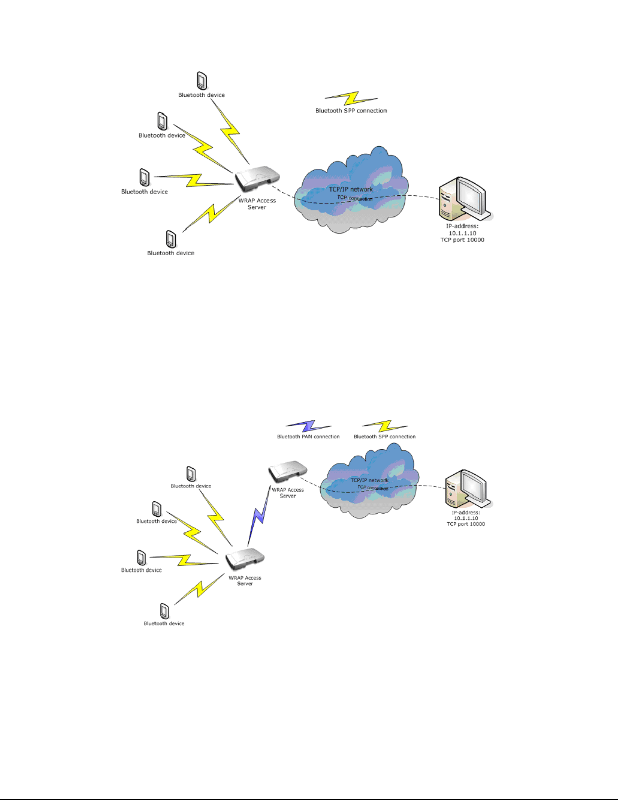
Chapter 4. SPP-over-IP
Figure 4-1. SPP-over-IP Network Architecture
All the server computer needs to do is to listen for incoming TCP connections from Access
Server to a specified TCP port and receive/send the application data.
4.1.2. Repeater Operation
The SPP-over-IP application can also be used in a so-called repeater mode. This feature is useful
when all Access Servers can not be directly connected to the TCP/IP network, but they can be
connected to other Access Servers by using Bluetooth PAN-connection. PAN enables transmitting TCP/IP packets wirelessly over Bluetooth. The figure below illustrates this configuration:
Figure 4-2. Repeater Mode in SPP-over-IP
4.1.3. SPP-over-IP over GPRS
SPP-over-IP software can also be used over GPRS instead of wired Ethernet connection. This
42
Page 51
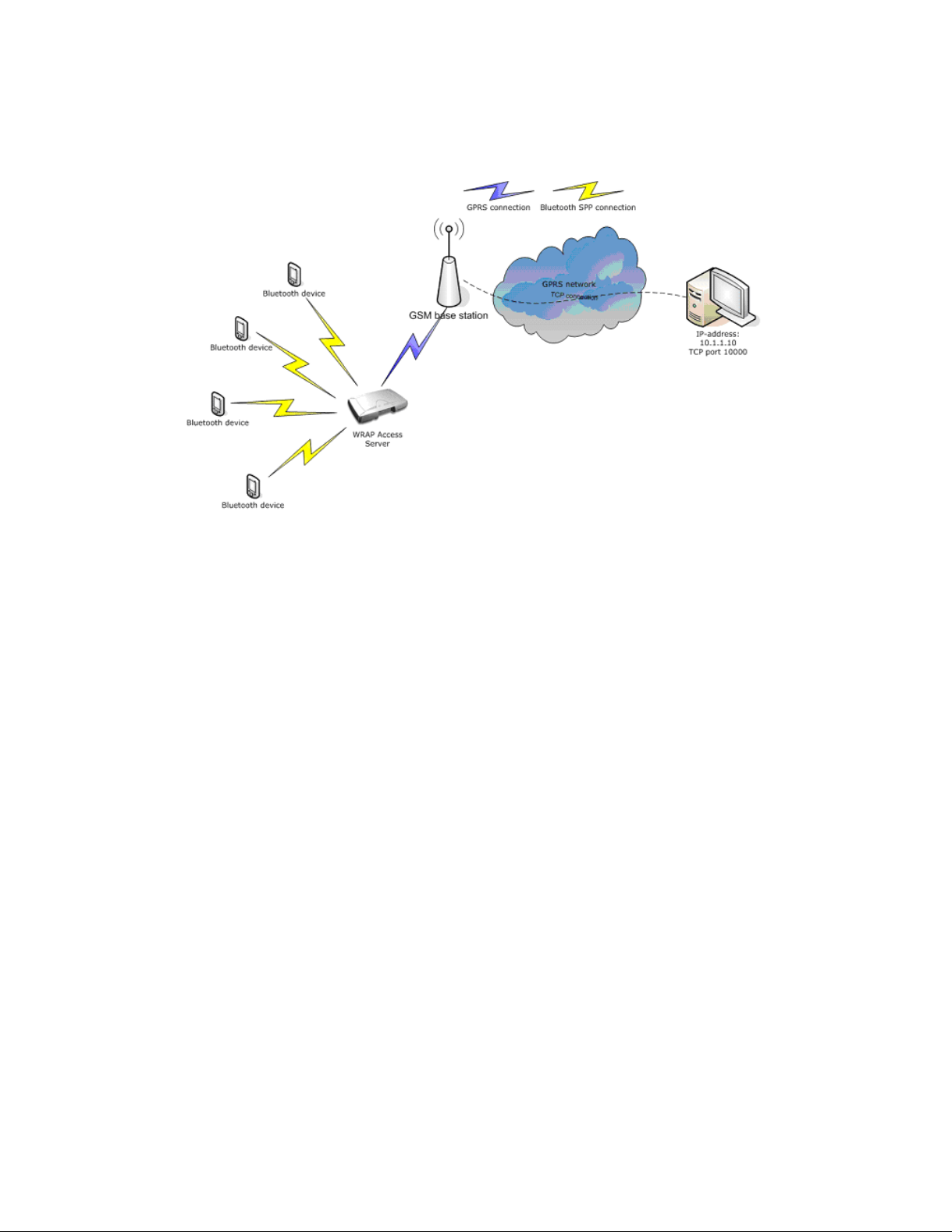
Chapter 4. SPP-over-IP
requires that Access Server is equipped with a working GSM/GPRS compact flash card. See
Appendix D for supported cards.
Figure 4-3. SPP-over-IP over GPRS
Notice when using GPRS:
• Data upload rate is around 8-12kbps (depending on GPRS card)
• Data download rate is around 32-48kbps (depending on GPRS card)
• Data transmission delays can be very high, sometimes even seconds
• GPRS connection may be unreliable and break easily. This should be taken account when
designing the system. If GPRS connection breaks, all the TCP and Bluetooth connections will
also be closed.
4.1.4. Opening Connections from Access Server
In the basic SPP-over-IP use case, Access Server is in passive mode and only accepts incoming
connections. Using connector service, Access Server can open and maintain outgoing Bluetooth
connections to defined Bluetooth devices
43
Page 52
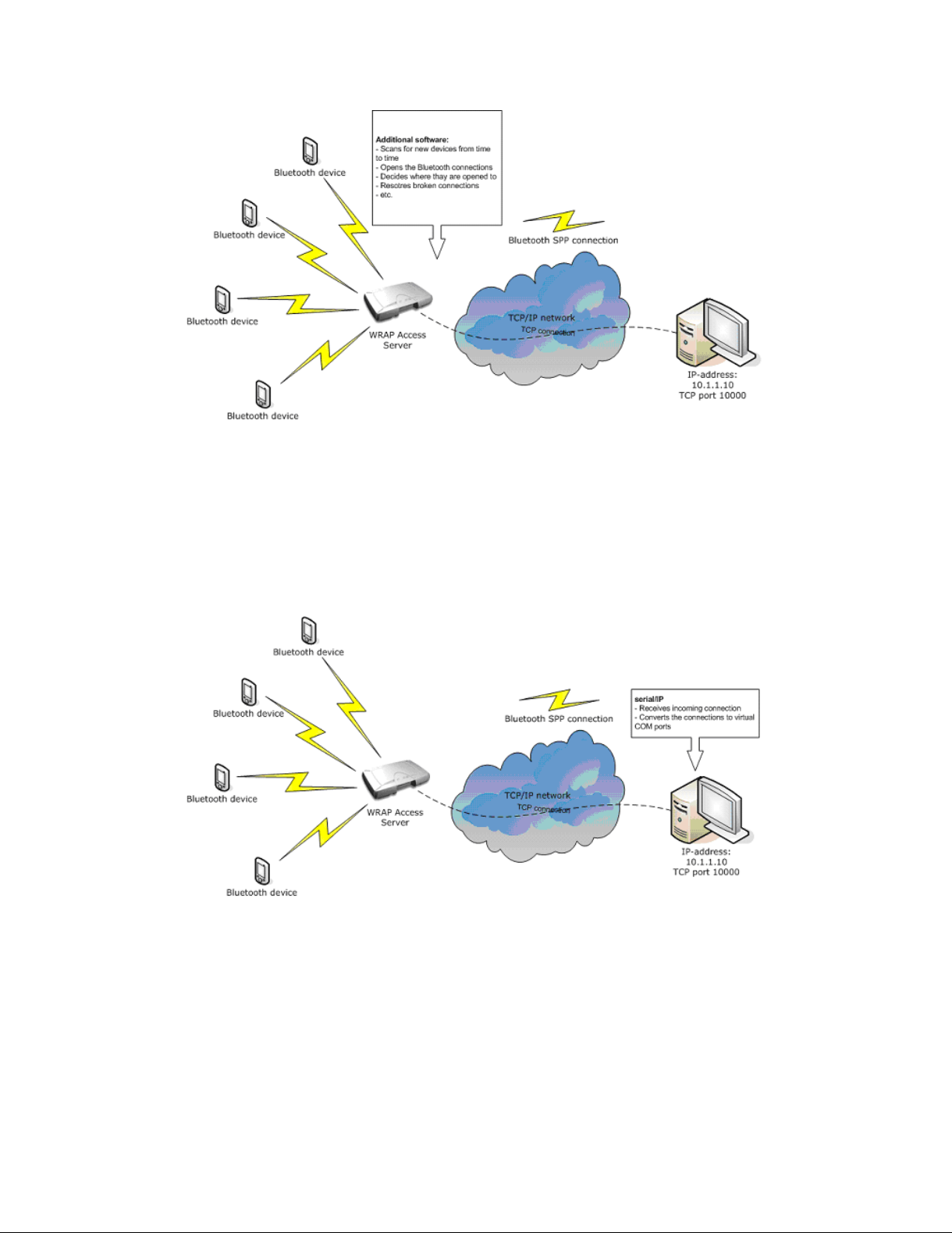
Chapter 4. SPP-over-IP
Figure 4-4. Access Server Opening the Connections
4.1.5. SPP-over-IP and COM Ports
SPP-over-IP can also be used together with Tactical Software’s Serial/IP® software. Serial/IP
software simply converts the TCP connections into virtual COM ports on the host computer.
This is very useful in applications, which do not have support for TCP/IP but support COM
ports instead.
Figure 4-5. SPP-over-IP with Serial/IP
An evaluation version of Serial/IP can be downloaded from:
http://www.tacticalsoftware.com/products/serialip.htm
4.2. Configuring SPP-over-IP
This chapter briefly instructs you to configure SPP-over-IP to work in different network setups
or use cases.
44
Page 53

Chapter 4. SPP-over-IP
SPP-over-IP is easiest to configure through WWW setup, which allows you to access all the
necessary configurations. For instructions about finding Access Server’s IP address and using
the WWW setup interface, see Section 2.2.
4.2.1. Forwarding Incoming Connections
The basic SPP-over-IP operation, listening incoming Bluetooth connections and forwarding
them to a TCP/IP socket on a remote host (or a local application), is configured at Setup −→
iWRAP settings −→ Bluetooth profiles −→ Connection forwarding. For details of the settings,
see Section B.5.1.5
4.2.2. Maintaining and Forwarding Outgoing Connections
The SPP-over-IP connector, which opens and maintains outgoing Bluetooth connections and
forwards them to a TCP/IP socket on a remote host (or a local application), is configured at
Setup −→ Applications −→ Connector. For details of the settings, see Section B.4.3
4.2.3. Repeater Configuration
If you want to configure Access Server also to act as a repeater (see
Figure 4-2) you must make
some additional configurations. Add the line below to your Bluetooth startup script, editable at
Setup −→ iWRAP settings −→ Edit startup script. Line starting with # is comment which can be
left out:
# Automatically connect to Access Server with PAN-NAP enabled using baseband 1
10101 SET CONTROL AUTOEXEC CALL 00:07:80:bf:01 PAN-NAP
You must replace the Bluetooth address used in the example (00:07:80:80:bf:01) with the Bluetooth address of the Access Server, on which you want to receive the PAN connection.
Note: The server receiving the PAN connection must have the PAN-NAP profile enabled. This is by
default not the case, so in setup or its WWW interface, ensure that the setting at −→ Bluetooth settings
−→ Bluetooth profiles −→ Enable PAN network access point profile says yes. No other configuration
is needed. See
Section 3.2.5 for more information on PAN profiles.
The Bluetooth PIN codes must be the same in both Access Servers.
In the example configuration (Figure 4-6) connection forwarding has already been configured
using the WWW Setup (two lines above the SET CONTROL AUTOEXEC line).
45
Page 54
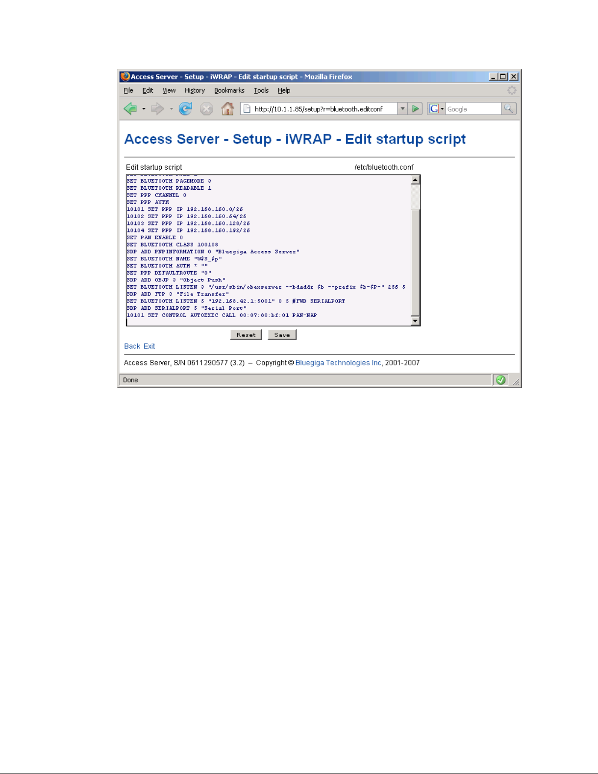
Chapter 4. SPP-over-IP
Figure 4-6. Repeater Configuration
4.2.4. Wi-Fi Configuration
If Access Servers must be connected to Wi-FI (WLAN) instead of physical Ethernet connection,
you also need to make additional configurations through the WWW setup.
See Section 3.3.3 for more information.
4.2.5. GPRS Configuration
If Access Servers must be connected to GPRS network instead of physical Ethernet or Wi-Fi
connection, you also need to make additional configurations through the WWW setup.
See Section 3.3.1 for more information.
46
Page 55
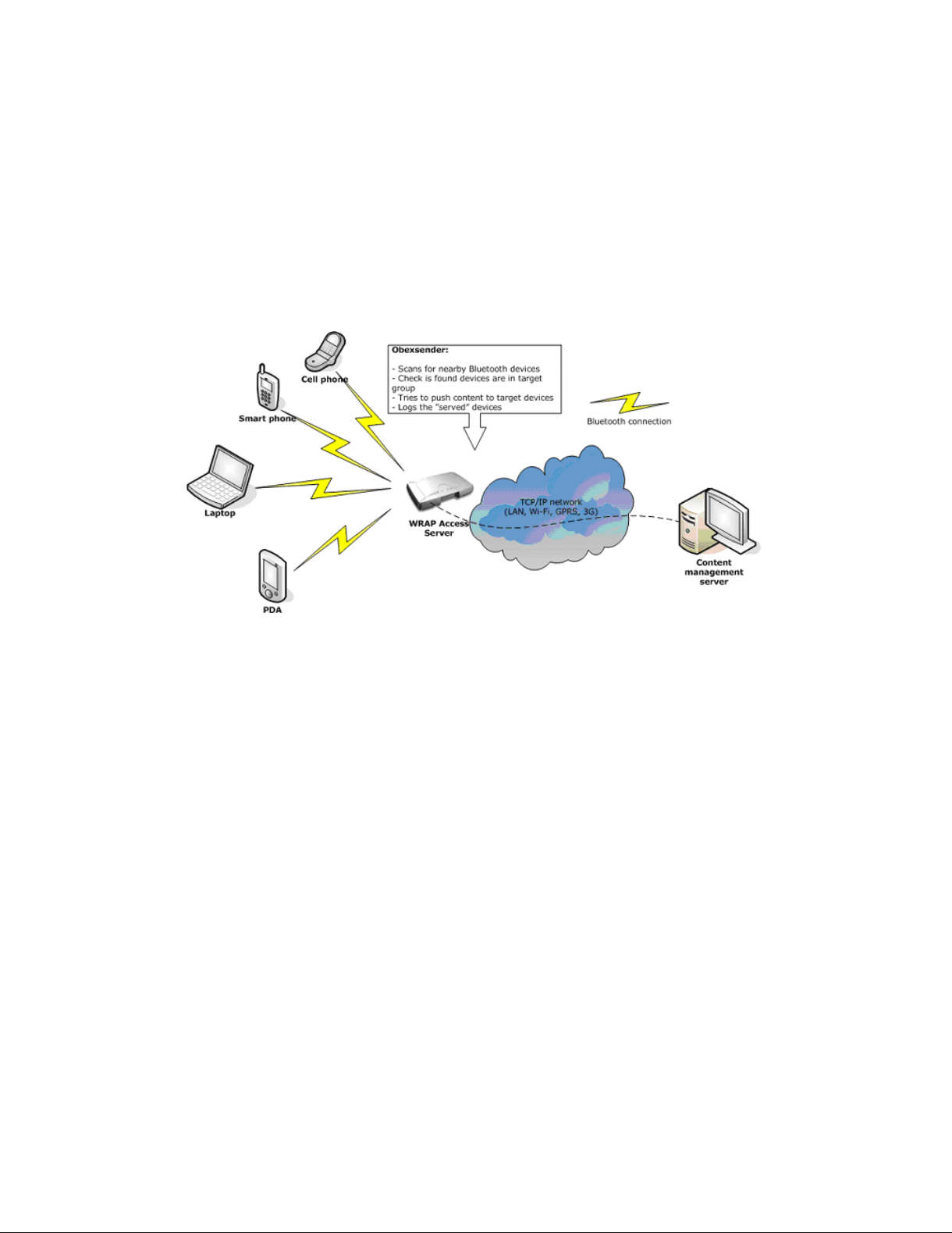
Chapter 5. Obexsender
Obexsender is one of the built-in applications in Access Server. It is dedicated to Bluetooth proximity marketing, content distribution, location based services, and much more. Access Server
plus Obexsender provide the user with a ready platform to start content distribution including
all the necessary Bluetooth functions from discovering the devices to transmitting the content.
The user needs to only focus on what, when, and to whom to send the content - rest is taken
care of by Access Server and Obexsender.
The figure below illustrates a simplified Obexsender network:
Figure 5-1. Simplified Obexsender network
5.1. Key Features
• Automatic device discovery and content push over a Bluetooth connection
• 18 simultaneous Bluetooth connections with one Access Server
• Upload speed even up to 75KB/sec with Bluetooth 2.0+EDR
• Content can be stored locally - with external memory even up to 2GB space
• Wide networking support: Bluetooth, Ethernet, Wi-Fi, GPRS and EDGE
• Secure remote connections over a Virtual Private Networking
• Remote file system support
• Lots of filtering options, such as device type, or distance from Access Server
• Extensive logging
• Interaction between several Access Servers
• Content time stamping
47
Page 56
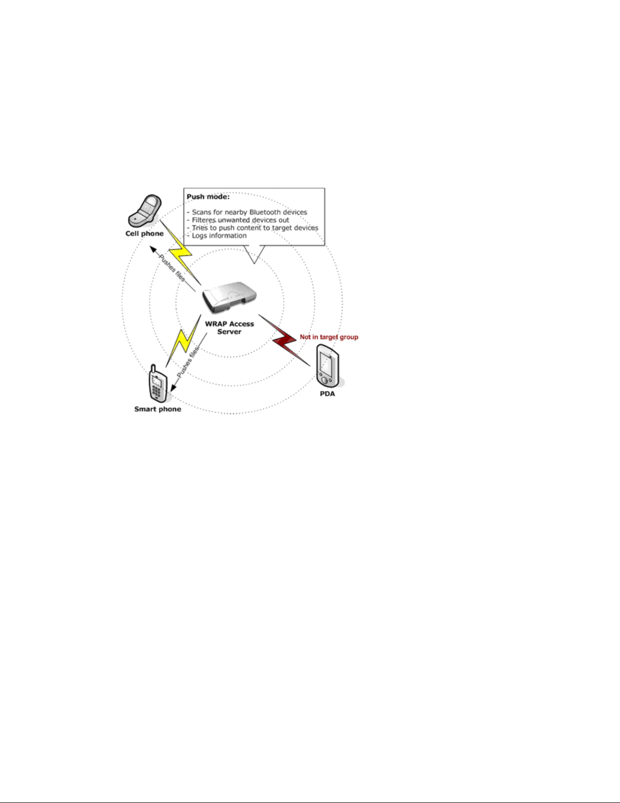
5.2. Use Cases
This chapter describes some possible ObexSender use cases.
5.2.1. Content Push
This is the standard functionality in ObexSender. In content push mode, ObexSender is scanning
for devices and pushing it to clients who belong to the target group (not opted out by filtering).
Chapter 5. Obexsender
Figure 5-2. ObexSender Use Case: Content Push
5.2.2. Content Pull
ObexSender can also be configured into a content pull mode. In this mode, the transaction is
initiated by the user. The user can send any file to the server or alternatively a file containing
some specific string such as "MP3" or "NOKIA N73". The server parses the received file and as
a response pushes a corresponding file to the user if such exists.
48
Page 57
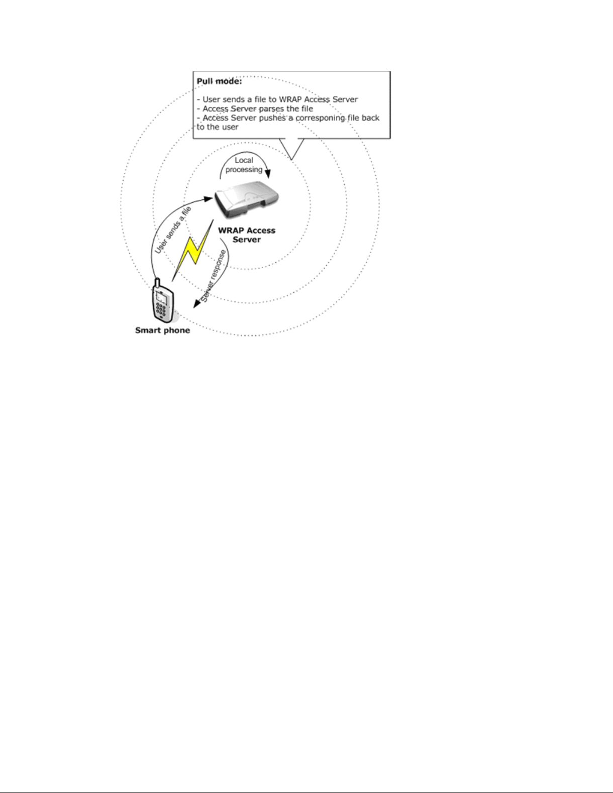
Chapter 5. Obexsender
Figure 5-3. ObexSender Use Case: Content Pull
5.3. Configuration
This chapter contains basic ObexSender configuration instructions. The easiest and fastest way
to configure ObexSender is through the WWW setup. For instructions about finding Access
Server’s IP address and using the WWW setup interface, see Section 2.2.
For details and default values of ObexSender configuration, please study the help texts in WWW
Setup interface (also in Section B.4.2) and the ObexSender configuration file, which can be
viewed and edited at Setup −→ Applications −→ ObexSender settings −→ Edit configuration
file.
Note: ObexSender will exit at startup by default, as it is not configured to do anything (there are no
active send or reply rules in the default configuration).
5.3.1. Uploading Files
ObexSender needs content (files) to be send for users. These can easily be uploaded by navigating to Setup −→ Applications −→ ObexSender settings −→ Upload a new file. All you need to
do is browse for the file you want to upload and click Upload. You will see a confirmation note,
for example "File /usr/local/obexsender/files/pic.jpg uploaded" .
At the moment, you can only upload to /usr/local/obexsender/files directory from
ObexSender main menu. If you would like to upload to another directory, you can do it from
Setup −→ Advanced settings −→ Browse all files menu.
You can also use secure FTP to transfer files (normal FTP is disabled by default in Access Server
for security reasons). For example WinSCP, available from http://www.winscp.org, is a good
application for secure FTP file transmissions.
49
Page 58

5.3.2. Configuring Content Rules
Specifying the content (files) to be sent by ObexSender is done by adding send and reply directives to ObexSender configuration file /etc/obexsender.conf. The file is editable at Setup
−→ Applications −→ ObexSender settings −→ Edit configuration file and also contains usage
examples of both directives.
5.3.3. How to Store Files Sent to Access Server
By default, all files sent over Object Push to Access Server are stored to the /tmp/obex directory
and deleted after they have been processed. It is however possible to save a copy of the file to
another directory before it is deleted. This is configured by adding the --fork with cp command
to the Optional parameters for server setting in Setup −→ iWRAP Settings −→ Bluetooth profiles
−→ Object push profile settings menu, following the example of parameters below:
--bdaddr $b --prefix $b-$P- --fork ’/bin/cp $$t /tmp/$$p$$d-$$T’
Now, after reboot, all incoming files are copied to /tmp directory. The format of the files is
bdaddr-btserverport-timestamp-filename.ext.
5.4. Monitoring ObexSender
Chapter 5. Obexsender
ObexSender logs its operation using syslog or to a specified log file (configurable via WWW
setup).
When you choose View log in the ObexSender menu, you can only see the summary of
ObexSender action, i.e how many successes, failures and retries have occurred. When you
select the date or Total in the summary view, you will see more details. You will see to which
Bluetooth address the content was sent and if the transmission was a failure or success, or if
transmission will be retried later.
5.5. Bluetooth Device Database
ObexSender uses special Bluetooth device database for recognizing Bluetooth devices. If you
find devices that are not identified properly, please send output of command Setup −→ Appli-
cations −→ ObexSender settings −→ Inquiry and calculate hash to <[email protected]>
together with detailed information, or at least the exact model of device identified with its Bluetooth address and friendly name, of devices found with that command, but improperly identified by ObexSender. Bluegiga Technologies will then provide you with the latest Bluetooth
device database.
50
Page 59

Chapter 6. Software Development Kit
6.1. Introduction to SDK
This chapter describes how to create and use applications by using Access Server’s Software
Development Kit.
The software running in Access Server can be divided to following categories:
1. Linux kernel and boot loader.
2. Bluegiga Access Server kernel device drivers (led, io, bbreset).
3. Bluegiga iWRAP Bluetooth stack, profiles (SPP, PAN, ObjP, FTP) and applications (for example ObexSender, connector and btcli).
4. Bluegiga servers (for example finder, smsgw and wpkgd) and applications (for example
setup and chkconfig).
5. GPLed applications (for example BusyBox, OpenSSH and bash).
6. Applications written with Software Development Kit.
6.2. Installing SDK
Note: The Software Development Kit can only be installed on a Personal Computer (PC) running the
Linux operating system.
6.2.1. Access Server Software Development Kit System Requirements
The following hardware and software are required to run the Access Server Development Kit:
A PC with:
• CD-ROM drive
• i386 Linux operating system (SDK has been tested with Foobar Linux 5, RedHat Enterprise
Linux 5, Fedora Core 6 and above; SuSE and Ubuntu (Feisty) are reported to work too). SDK
has not been tested on x86_64 platform.
gcc, autoconf, make, bison, byacc, flex, gawk and ncurses must be installed
Devel libraries (especially glibc-devel, zlib-devel, openssl-devel, e2fsprogs-devel,
readline-devel and ncurses-devel) must be installed
• 300MB of available hard disk space
An Ethernet connection to a Local Area Network (also connected to Access Server) is highly
recommended.
Mount the Access Server SDK CD-ROM or ISO image, change the current working directory
to where it is mounted, and run the install script. If the user running install does not have
privileges to create the directory for the toolchain, normally /usr/local/arm, the install script
prompts for root’s password.
Example (user input is printed like this):
51
Page 60

Chapter 6. Software Development Kit
$ mount /dev/cdrom /mnt/cdrom
$ (or mount -o loop /path/to/sdk2.iso /mnt/cdrom)
$ cd /mnt/cdrom
$ sh install
During the installation, the system will prompt you with some questions (described below)
regarding the components to install and the paths to install them to. If you are not familiar with
Linux, just press enter to these questions to accept the default values. The default values are
suitable for most users and systems.
6.2.2. Questions Asked by the Install Script
Access Server toolchain directory (default: /usr/local/arm)
This is the path where you want the Access Server Software Development tools
(arm-linux-gcc, etc.) to be installed.
Note: If you change this value, the Access Server tools and libc must be recompiled. The recompila-
tion process is complicated and lengthy, and it can also fail, depending on your system. Recompilation
is automatically done by the install script, if necessary.
Development directory (default: [home_of_current_user]/asdk)
This is the path where you want the Access Server Software Development Kit to be installed.
Development directory owner (default: [current_user])
(Asked only if run as root.) This is the development directory owner’s username.
Note: If this is not the username of the developer for whom the Software Development Kit is being
installed, the user will not have rights to use the development files and therefore can not develop any
Access Server software.
Install toolchain sources (default: no - unless the tools directory was changed)
This value indicates whether the toolchain sources will be installed. The sources are only required if the Access Server tools directory was changed from the default target location in step
1.
Compile image after installation (default: yes)
If set to yes, the install script will compile the Access Server filesystem image to test that the
installation was successful and that the Development Kit is working correctly.
6.3. Creating Applications
The fastest way to start developing Access Server applications is to study, change, and recompile
the example files in the asdk/examples directory.
6.3.1. Application Examples
To demonstrate the software development features of Access Server, the Access Server Software
Development Kit comes with several example applications.
52
Page 61

Chapter 6. Software Development Kit
6.3.1.1. Installing Examples
The compiled example files are located in WPK packets on the Access Server SDK tree in subdirectories of directory asdk/examples.
The examples can be manually uploaded and installed on Access Server by sending them to
the /tmp/obex directory. The wpkgd server automatically installs them. Uploading can be done
over Bluetooth, SCP, SFTP or WWW Setup −→ Advanced −→ Upload a software update (see
Figure 2-14).
6.3.1.2. Running Examples
The examples, with their usage and purpose, are described in Table 6-1.
Example Usage Purpose
helloworld /usr/bin/helloworld The "Hello, world!" application.
serial /usr/bin/serial /dev/ttyAT1 "Hello, world!" to the serial port.
Notice that /dev/ttyAT1 must be
free (no WRAP SMS Gateway or
Bluetooth Serial Port Profile is using
it).
forkserver SET BLUETOOTH LISTEN 11
/usr/bin/forkserver
btlogger SET BLUETOOTH LISTEN 11
/usr/bin/btlogger /tmp/logfile
btserver /usr/bin/btserver - for server mode
(if no forkserver is running),
/usr/bin/btserver <bdaddr of
btserver in server mode or
forkserver> 11 for client mode
ledtest /usr/bin/ledtest I/O: LED example.
m2n echo testmessage | /usr/bin/m2n This is a Machine-2-Network (M2N)
This is the simplest Bluetooth
RFCOMM server example. Use, for
example, btserver as a client to test
this example. This example waits for
a full line from the client, echoes is
back and then exits.
This is a simple Bluetooth
RFCOMM server example, which
logs lines received from the
connected client, and answers with
"ACK". Use, for example, btserver
as a client to test this example.
This is an advanced iWRAP client
example, which can run both as an
RFCOMM server, when it works as
forkserver, or as a client, when it
sends "YooHoo" to remote server,
waits, displays the response, and
quits).
example. For actual remote
connection, syslog must be
configured to log to a remote syslog
server.
53
Page 62

Chapter 6. Software Development Kit
Example Usage Purpose
www
Browse to http://wrap-ipaddress/example.html
Demonstration of the web server
capabilities.
makesms Browse to
http://wrap-ip-address/send.html.
Notice that this example assumes
that WRAP SMS Gateway is up and
running (see Section 3.5.3).
setup-helloworld Install the generated WPK and
navigate in WWW Setup
lottery Install the generated WPK and
uncomment exec example in
/etc/obexsender.conf
Table 6-1. Examples, Their Usage and Purpose
This example demonstrates WRAP
SMS Gateway by sending SMS
messages with it.
This example demonstrates how to
add a new helloworld submenu to
the WWW Setup, with two menu
items that change the variables in
/etc/sysconfig/helloworld file.
This example demonstrates the how
ObexSender responses can be
generated from an application.
6.3.2. Creating a New Project
To start a new project, you must create a new subdirectory in your Development Kit’s directory
(asdk/) and add your application source files and Makefile to that directory.
A project skeleton can be automatically created by using the Access Server Project AppWizard.
Just give the make appwiz APP=dir/to/newapp command in the Development Kit’s top level
directory (asdk/). A "hello world" example ANSI C project is then created.
To use C++ compiler, replace $(do_link) with $(do_link_cc) in Makefile.
The details of the compile process and variables you may need to modify before compiling your
application, such as CFLAGS, LDFLAGS and CXXFLAGS, can be seen in file asdk/Rules.mak.
Now you have a new project waiting for coding. To compile the project, run make in the
asdk/dir/to/newapp directory.
The build system also creates the installation packet (hello-timestamp.wpk), which can be
transferred to the /tmp/obex directory of Access Server from where it is installed automatically.
6.3.3. Building from the Command Line
The Access Server Development Kit uses the ARM port of the GNU bintools and compilers to
build applications. If you are not familiar with Linux development, use the method explained
in the previous section instead of writing your own makefiles.
If you still want to use your own development environment, there are two minor issues to remember:
1. Tools are prefixed with arm-linux-, so for calling the gcc C-compiler, you must call arm-
linux-gcc, and so on.
54
Page 63

Chapter 6. Software Development Kit
2. Tools are located in /usr/local/arm/3.4.5/bin/ directory, which is not in PATH by default.
6.3.4. Transferring an Application to Access Server
To run an application on Access Server, it must first be transferred to it. There are several ways
of doing this (see Section 2.3.3). The most convenient ways in conjunction with software development are discussed in the following subsections.
6.3.4.1. Transferring an Application Using SCP or SFTP
An SCP transfer is done with a single command. In the following example, myapp is transferred
to the /tmp directory in Access Server:
$ scp myapp root@<wrap-ip-address>:/tmp
root@<wrap-ip-address>’s password: buffy (not echoed back)
/path/to/myapp/myapp 100% 20KB 20.0KB/s 00:00
$
An SFTP transfer is almost similar, but the command procedure resembles an FTP session (FTP
can also be used if the FTP server is enabled):
$ sftp root@<wrap-ip-address>
Connecting to <wrap-ip-address>...
root@<wrap-ip-address>’s password: buffy (not echoed back)
sftp> cd /tmp
sftp> put myapp
Uploading myapp to /dev/shm/tmp/myapp
/path/to/myapp/myapp 100% 20KB 20.0KB/s 00:00
sftp> quit
$
6.3.4.2. Using SSHFS
With SSHFS, the Access Server filesystem can be securely mounted to be a part of the development host’s filesystem.
To download and install SSHFS, visit http://fuse.sourceforge.net/sshfs.html. After installation
you can mount the whole filesystem and copy the myapp application to the /tmp directory in
Access Server by using the following commands:
$ mkdir mnt
$ sshfs root@<wrap-ip-address>: mnt
root@<wrap-ip-address>’s password: buffy (not echoed back)
$ cp myapp mnt/tmp
$ fusermount -u mnt
$
6.3.4.3. Transferring an Application Using Terminal Software
If your Access Server is not connected to a LAN, you can use terminal software of your choice
to transfer data to Access Server.
55
Page 64

Chapter 6. Software Development Kit
Access Server contains an X/Y/Zmodem protocol application, which allows you to transfer
data over the console using almost any terminal software available:
1. Connect your computer to the Access Server management UART using a cross-over serial
cable, and start your terminal software (use settings: 115 200bps, 8 data bits, no parity, 1 stop
bit).
2. Change your working directory to where you want to upload your application, and run the
Xmodem application with your application name as a parameter.
3. Start Xmodem send from your terminal software.
Example 6-1. Transfering Files with Xmodem
[root@wrap /] cd /tmp
[root@wrap /tmp] rx testapp
rx: ready to receive testapp.
now start xmodem (checksum, not CRC) send from your terminal
[root@wrap /tmp]
If you want to save the application to /usr/local/bin (on the flash file system), you will have
to replace cd /tmp with cd /usr/local/bin (and possibly create the directory, if it does not exist).
To examine Access Server directory structure, please see
Appendix A.
6.3.4.4. Using NFS Mount
To use NFS mount, have a NFS share prepared in your development PC and mount the directory
by using command mount -o nolock <dev-pc-ipaddress>:/nfsshare /mnt/nfs. After this, you
can access the share in directory /mnt/nfs.
When the share is not needed, unmount it with command umount /mnt/nfs
6.3.4.5. Using CIFS Mount
To use CIFS mount, have a CIFS share (for example a shared folder in Windows) available in
you PC and cifs-client.wpk installed to Access Server. Mount the directory by using command mount.cifs //ipaddr-of-pc/sharename /mnt/nfs -o username. You will then be prompted
for password for the username you specified. After entering correct password, you can access
the share in directory /mnt/nfs.
When the share is not needed, unmount it with command umount /mnt/nfs
6.3.5. Running an Application Transferred to Access Server
To run the application you just transferred to Access Server, you need access to the Access Server
console, either using terminal software connected to the Access Server management UART or
using the SSH connection (log in as user root and the root password, which is buffy by default).
Having established a connection to Access Server, change the directory to where your application is located and change file permissions so that it can be executed, then run it.
56
Page 65

Chapter 6. Software Development Kit
Example 6-2. Running an Application
[root@wrap /] cd /tmp
[root@wrap /tmp] chmod 755 testapp
[root@wrap /tmp] ./testapp
6.3.6. Using GNU Project Debugger (GDB)
You can use GDB, the GNU Project debugger, to debug applications in Access Server. This requires that you install gdbserver-
CD or from asdk/arch/arm/gpl/gdbserver/ directory on your development PC.
To debug an application it has to be compiled with debugging options enabled and stripping
disabled. This can be done by overriding the default CFLAGS variable. You can do this by modifying the Makefile for your project:
# Makefile
SDKBASE=/home/user/asdk
include $(SDKBASE)/Rules.mak
CFLAGS=-Wall -Os -ggdb -I$(SDKBASE)/include -L$(SDKBASE)/lib
.wpk package to Access Server. You can find it from SDK
*
ifdef SDKINSTALL
...
After you have compiled your application with these options and transferred it to Access Server,
you can start debugging the application as follows:
1. Start gdbserver on Access Server. For example:
gdbserver :6789 /tmp/hello
2. Start arm-linux-gdb on development PC. For example:
/usr/local/arm/3.4.5/bin/arm-linux-gdb \
-ex ’set solib-absolute-prefix /usr/local/arm/3.4.5/arm-linux’ \
-ex ’target extended-remote Access_Server_IP:6789’ \
hello
3. Run the application by using continue command.
You can also use Data Display Debugger (DDD), a graphical front-end to GDB. Start it as:
ddd --debugger "/usr/local/arm/3.4.5/bin/arm-linux-gdb \
-ex ’set solib-absolute-prefix /usr/local/arm/3.4.5/arm-linux’ \
-ex ’target extended-remote Access_Server_IP:6789’" \
hello
6.3.7. Native SDK
It is also possible compile applications for Access Server using native toolchain. To use it, copy
files sdk.iso and sdkmount.wpk from directory lib in the Access Server SDK CD-ROM (or ISO
57
Page 66

Chapter 6. Software Development Kit
image) to the root directory of an USB memory dongle, and insert it to Access Server’s USB port.
(You can also use Compact Flash memory card for this purpose in similar manner). The native
SDK is automatically mounted and you can start using the compiler (gcc) in Access Server. All
tools now available can be found in directory /usr/sdk/bin.
58
Page 67

Chapter 7. iWRAP - The Bluetooth API
The Bluetooth service in Access Server is controlled via a TCP socket interface, called iWRAP.
The first iWRAP server is listening on port 10101. In case of Access Server 2293, the second
iWRAP server is listening on port 10102, and the third one is listening on port 10103. All commands to the iWRAP server and replies from the server are plain ASCII strings ending in CR+LF
("\r\n"). Commands and replies are not case sensitive.
When connecting to iWRAP, you must first wait for the READY. prompt. Do not send any commands prior to this.
By default the connection to iWRAP is protected by a password. The default password is buffy.
The password can be disabled or changed. For more information, see SET command. If the
password is enabled, it must be sent first, immediately following the READY. prompt. Otherwise
all commands will fail with an error code.
Some replies are broadcasted to all clients by the iWRAP server. If you see something that you
have not requested or the reply is not intended to you, simply ignore the reply.
In the following examples, bold lines are commands sent by the client to the iWRAP server
and normal lines are replies received from the iWRAP server by the client.
7.1. Terms
Bluetooth address (bdaddr) consists of six hex digits separated by a colon. For example,
"00:07:80:80:bf:01". With commands requiring a Bluetooth address, you can also use the
Bluetooth friendly name instead.
Bluetooth RFCOMM channels are numbered from 1 to 30. In Access Server, Serial Port Profile is
assigned to channel number two, Object Push Profile and File Transfer Profile to channel number
three, and LAN Access Profile is on channel number four. The other channels are free for user
applications.
Link Identifier (link_id) is a number from 0 to 99. It is used to identify established Bluetooth
connections.
7.2. Starting iWRAP
Normally, the iWRAP servers are started automatically upon power-up. You can restart them
manually (for example, to apply changes made to the iWRAP settings with the setup application
without rebooting the system). To restart the servers manually, execute the startup script with
option restart:
[root@wrap /] service bluetooth restart
When the iWRAP servers start up, they use settings configured with the
can put additional iWRAP commands to /etc/bluetooth.conf file. Commands in that file are
processed as the last task every time the iWRAP server is started.
setup application. You
59
Page 68

7.3. Writing iWRAP Applications
There are two approaches when writing a iWRAP server program (a program accepting incoming calls) for Access Server, both having different pros and cons:
1. Forklistener
2. iWRAP Client
Note: When writing a client program (that is, a program making an outgoing call), you have to use
iWRAP.
7.3.1. Forklistener
This is a standard program reading data from standard input and writing output to standard
output. See the SDK directory examples/forkserver/ for an example of this kind of program.
Pros:
• Easy to write.
• Very robust for simple services.
• You do not have to understand Bluetooth or iWRAP.
Chapter 7. iWRAP - The Bluetooth API
Cons:
• Your program is started and stopped for every incoming connection.
• If there are multiple connections, it is not possible to communicate to an external program
through one socket.
• You cannot use stdout for debugging; you must use syslog or a log file.
• iWRAP’s advanced features are not available: powermodes, MSC, SDP, inquiry, ...
To setup a forklistener, see the SET command.
7.3.2. iWRAP Client
iWRAP client is a program communicating with the iWRAP server through control and data
sockets. See the SDK directory examples/btserver/ for an example of this kind of program.
Pros:
• The cons with forklistener do not apply.
Cons:
• More complex than forklistener.
• You must have basic knowledge about Bluetooth and iWRAP.
• If you have multiple iWRAP clients (which is usually the case), some kind of IPC is usually
needed. For example, if client #1 uses CALL command, client #2 may not do the same before
client #1 receives RINGING reply. The easiest way to do this is to use LOCK command.
60
Page 69

7.4. btcli - iWRAP Command Line Interface Utility
You can send iWRAP commands from the command line by using the btcli application.
Usage:
btcli [options] command
To see the command options, enter the btcli --help command.
The specified command is sent to iWRAP server (the first server at port 10101 by default) and
all replies are echoed to the standard output. The application waits and prints the replies for a
certain amount of time (6 seconds by default) and exits.
7.5. iWRAP Commands
INFO
INFO — Get basic info
Synopsis
INFO
Description
INFO is used to retrieve version information on the iWRAP server, in the same format as presented by the READY. prompt when the iWRAP connection is opened.
Reply
READY. (wrap-2-1-0 $Revision: 1.28 $ bt1.2)
61
Page 70

QUIT
QUIT — Close iWRAP connection
Synopsis
QUIT
Description
To close the connection to the iWRAP server, use the QUIT command.
Reply
There is no reply.
Example
READY.
QUIT
62
Page 71

SET
SET — Change parameters
Synopsis
SET [variable [value] ]
Description
The SET command allows you to alter various Bluetooth and iWRAP parameters. The supported variables are listed in Table 7-1. Issuing a SET command without parameters lists the
current settings.
Variable Description
BLUETOOTH BDADDR bdaddr Our bdaddr. This is a read-only value.
BLUETOOTH NAME friendly_name You can set your Bluetooth friendly name with this
command. Others can request this name with the
NAME command. You can use the following meta
characters:
$S: Hardware serial number, all ten digits
$s: Hardware serial number, last three digits
$P: iWRAP port
$p: last digit of iWRAP port
$H: FQDN
$h: hostname
$b: our Bluetooth address, last two digits
$B: our Bluetooth address
$$: $
The default value is $S_$p.
BLUETOOTH READABLE mode If enabled, some SDP result codes will have literal
values instead of numeric values.
0: No (always use numeric values)
1: Yes (literal values)
63
Page 72

Variable Description
BLUETOOTH CLASS value You can set the class-of-device value with this
command.
BLUETOOTH ROLE role {policy
{timeout}}
You can set the master/slave role switch preference
with this command. Optionally, you can also set the
link policy and link supervision timeout. The possible
values for "role" are:
0: allow when calling, do not request when answering
1: allow when calling, request when answering
2: do not allow when calling, request when answering
The default link policy is 000f and the default link supervision timeout is 7d00. See Bluetooth Specification for
more information on these parameters.
BLUETOOTH ENCRYPT value This command defines whether to use Bluetooth
encryption. To actually enable Bluetooth encryption,
the connection must be authenticated.
0: No
SET
1: Yes
BLUETOOTH LAP value You can set the IAC LAP value with this command.
The default value is 9e8b33
64
Page 73

Variable Description
BLUETOOTH PAGEMODE mode
{page_timeout
{page_repetition_mode
Pagemode defines whether other devices can find and
call you. There are four different modes:
0: No inquiry, no paging
{scan_activity_interval
scan_activity_window
1: Inquiry, no paging
{inquiry_activity_interval
inquiry_activity_window}}}}
2: No inquiry, paging
3: Inquiry and paging
The page timeout is given in hex and the default value
is 2000. The default page repetition mode is 2 (R2). The
default scan activity is interval 0800 and window 0012
(R1). The default inquiry activity is interval 0800 and
window 0012 (R1).
See the Bluetooth Specification for more information on
these parameters.
SET
BLUETOOTH AUTOHIDE physical
logical
This command automatically hides the baseband (sets
pagemode to 0) if there are more physical ACL links
or logical connections than defined. Value 0 means
"don’t care".
Default values: 7 0
BLUETOOTH AUTH * {authflags} This command removes the default PIN code. If you
are making an outgoing connection and the remote
end asks for the PIN, "1234" will be sent.
BLUETOOTH AUTH * pin
This command sets the default PIN code.
{authflags}
BLUETOOTH AUTH bdaddr
This command removes the PIN code for bdaddr.
{authflags}
65
Page 74

Variable Description
BLUETOOTH AUTH bdaddr pin
{authflags}
This command sets the PIN code for bdaddr.
Authflags are:
--NEWPAIR Only if we do not have linkkey yet
--REQUEST Request this PIN from remote, do not re-
ply with this one
--REPLY Reply to remote requests with this PIN
--CALL Only if making an outgoing call
--ANSWER Only when answering to an incoming call
--RFCOMM Call type is RFCOMM (includes
FORK/PPP/...)
--BNEP Call type is BNEP
--L2CAP Call type is L2CAP
SET
Default authflags are all enabled, except for --
NEWPAIR.
There are three special PINs:
- Reject without asking PIN.
-- Reject on the connection open, do not check for call
types.
+ Accept without asking PIN.
BLUETOOTH PAIR bdaddr linkkey With this command, you can manually set the linkkey
for bdaddr.
Note: SET BLUETOOTH AUTH must also be set for a
value to enable encrypted connections with previously
stored link keys.
BLUETOOTH PAIR bdaddr With this command, you can manually delete the
linkkey for bdaddr.
BLUETOOTH PAIREXPIRE seconds With this command, you can set the expiration time, in
seconds, for pairing information.
66
Page 75

Variable Description
BLUETOOTH LISTEN channel cmd
{mem {delay}}
This command adds a fork-listener for the channel.
When there is an incoming RFCOMM connection to
the channel, the iWRAP server handles the connection
by itself by forking "cmd". At least "mem" kilobytes of
free memory must be available, or the connection will
be rejected. After forking, the iWRAP server waits for
"delay" timerticks (50ms) before transmitting any
data.
The client application must modify both the stdout and
stdin pipes and set NOECHO, 8BIT and all other nec-
essary modes at the very beginning. The purpose of
the "delay" parameter is to give the application enough
time to do this.
You can use following meta characters in "cmd":
$b: Bluetooth address.
$c: RFCOMM channel
SET
$d: 1 if CALL, 0 if RING
$P: iWRAP port
$C: link_id
$$: $
BLUETOOTH LISTEN channel
host:port
This command adds a forward-listener for the channel.
When there is an incoming RFCOMM connection to
the channel, the iWRAP server will forward it to
host:port by using a raw TCP socket.
BLUETOOTH LISTEN psm L2CAP This command adds an L2CAP listener for the psm.
BLUETOOTH LISTEN psm
L2CAP:host:port
This command adds a forward-listener for the psm.
When there is an incoming L2CAP connection to the
psm, the iWRAP server will forward it to host:port by
using a raw TCP socket.
BLUETOOTH LISTEN channel This command removes a fork/forward/L2CAP
listener from the channel/psm.
67
Page 76

Variable Description
BLUETOOTH LINK mode params
With this command, you can modify the slave’s
powermode according to the "mode". "params" are
optional and mode-dependent. The possible values
for "mode" are:
0: Active.
Params: None.
1: Park: Round-robin.
Params: max_beacon min_beacon sleep_after_unpark
sleep_after_round
Defaults: 254 160 5 30
Sleeps are specified by timerticks (50ms).
2: Park: Idle.
Params: max_beacon min_beacon max_active
SET
Defaults: 512 384 6
max_active is the maximum number of active slaves.
3: Sniff: All.
Params: max_interval min_interval attempt timeout
Defaults: 640 426 1 8
4: Sniff: Idle.
Params: idle_timeout max_interval min_interval at-
tempt timeout
Defaults: 400 640 426 1 8
idle_timeout is in timerticks (50ms).
See Bluetooth Specification for more information on
params.
68
Page 77

SET
Variable Description
BLUETOOTH QOS service_type
token_rate peak_bandwidth latency
delay_variation
This command sets default QoS values for a new
connection. The parameters are in hex. See Bluetooth
Specification for more information on params.
Defaults: 01 00000000 00000000 000061a8 ffffffff
L2CAP TIMEOUT flushto linkto With this command, you can define the FlushTimeout
and LinkTimeout for L2CAP connections. See
Bluetooth Specification for more information on params.
Defaults: 65535 40000
PPP AUTH Do not require any PPP authentication on incoming
connections.
PPP AUTH username password Require specified username:password on incoming
PPP connections.
PPP CHANNEL channel Our PPP (LAN Access Profile) channel. The iWRAP
server handles this channel internally. If you change
this, remember to modify the SDP record as well. Use
zero value to disable the LAN Access Profile.
PPP DEFAULTROUTE value This setting controls whether the iWRAP server
should modify the defaultroute setting. There are four
different modes:
0: Do no alter defaultroute
1: Set defaultroute according to the outgoing PPP
2: Set defaultroute according to the incoming PPP
3: Set defaultroute according to all PPP calls
PPP WINHANDSHAKE seconds Timeout to wait for the Windows RAS handshake.
PPP IP ipaddr/mask This command sets the network IP range for PPP
clients.
69
Page 78

SET
Variable Description
PAN ENABLE bitmap This command controls incoming PAN connections.
Bitmap:
1: Allow incoming PAN-PANU connections.
2: Allow incoming PAN-GN connections.
4: Allow incoming PAN-NAP connections.
8: Enable zeroconf for incoming PAN-PANU connec-
tions.
16: Enable zeroconf for outgoing PAN-PANU connec-
tions.
Defaults: 0
CONTROL AUTOEXEC cmd Run the CALL command, and rerun it when the call is
disconnected. Example: SET CONTROL AUTOEXEC
CALL bdaddr PAN-NAP PAN-NAP
CONTROL PASSWORD Do not require a password from iWRAP clients.
CONTROL PASSWORD pass
{--LOCAL}
Enable password. iWRAP clients must send this
password before giving any other command. The
password is case sensitive.
With an optional --LOCAL parameter, clients connect-
ing from localhost are accepted without a password.
CONTROL PING seconds
If this setting is enabled (seconds > 0), the iWRAP
server sends a PING reply to all iWRAP clients. You
have to reply to it with PONG or the connection will
be closed.
CONTROL WRITETIMEOUT
timeticks
With this command, you can set in timeticks (1/20s)
how long iWRAP tries to write to the datasocket if it’s
blocked before giving up and closing the connections.
CONTROL AUTOSAVE what
filename
If this setting is enabled, the system automatically
saves settings to a file when they change. See the SAVE
command for possible "what" values.
link_id MSC value Set MSC for link_id to value. See ETSI TS 101 369
(GSM 07.10) for more information.
link_id ACTIVE With this command, you can set the powermode for a
link_id to active.
70
Page 79

Variable Description
link_id PARK params With this command, you can set the powermode for
link_id park. Required "params" are:
avg_beacon or
max_beacon min_beacon
See Bluetooth Specification for more information on
params.
link_id HOLD params With this command, you can set the link’s
powermode to hold. Required "params" are:
avg
max min
See Bluetooth Specification for more information on
params.
SET
link_id SNIFF params With this command, you can set the powermode for a
link_id to sniff. Required "params" are:
avg_interval or
max_interval min_interval or
max_interval min_interval attempt or
max_interval min_interval attempt timeout
The default attempt is 1, the default timeout is 8.
See Bluetooth Specification for more information on
params.
link_id QOS service_type token_rate
peak_bandwidth latency
delay_variation
With this command, you can set the link’s QoS values.
The parameters are in hex.
See Bluetooth Specification for more information on
params.
link_id MASTER With this command, you can switch the role to master.
link_id SLAVE With this command, you can switch the role to slave.
Table 7-1. Supported Parameters for iWRAP SET Command
71
Page 80

Reply
When there are parameters, there is no reply.
Example
READY.
SET BLUETOOTH NAME Buffy
SET BLUETOOTH PAGEMODE 3
SET BLUETOOTH READABLE 1
SET BLUETOOTH CLASS 020300
SET BLUETOOTH ROLE 0
SET BLUETOOTH ENCRYPT 0
SET BLUETOOTH PAGEMODE 3
SET BLUETOOTH AUTH*1234
SET BLUETOOTH AUTH 00:07:80:80:bf:01 4242
SET BLUETOOTH AUTH
SET BLUETOOTH PAIREXPIRE 600
SET BLUETOOTH LISTEN 1 /bin/login 200
SET BLUETOOTH LISTEN 2 "my/own/command with parameters" 100 5
SET BLUETOOTH LISTEN 3
SET PPP DEFAULTROUTE 0
SET PPP AUTH buffy willow
SET PPP AUTH
SET PPP CHANNEL 4
SET PPP WINHANDSHAKE 10
SET PPP IP 192.168.166.0/24
*
SET
SET 0 MSC 8d
SET CONTROL PING 60
PING
PONG
SET CONTROL PASSWORD
SET CONTROL PASSWORD buffy
<client reconnects>
READY.
SET
ERROR PASSWORD NEEDED.
<client reconnects>
READY.
buffy
SET
SET BLUETOOTH BDADDR 00:07:80:80:bf:01
SET BLUETOOTH NAME Buffy
SET PPP AUTH
SET CONTROL PASSWORD buffy
SET
72
Page 81

SAVE
SAVE — Save iWRAP settings
Synopsis
SAVE {what} {filename}
Description
The SAVE command writes the current settings to a file.
What Settings
AUTH SET BLUETOOTH AUTH ...
PAIR SET BLUETOOTH PAIR ...
BTSET SET BLUETOOTH ..., but not AUTH or PAIR
OTHERSET All but SET BLUETOOTH
ALL Everything
Table 7-1. SAVE parameters
Reply
There is no reply.
Example
READY.
SAVE PAIR /etc/bluetooth.pair
SAVE AUTH,PAIR /etc/bluetooth.security
73
Page 82

LOAD
LOAD — Run iWRAP command script
Synopsis
LOAD {filename}
Description
The LOAD command runs commands from a file. This command is usually used with SAVE or
SET CONTROL AUTOSAVE commands.
Reply
There is no reply.
Example
READY.
LOAD /etc/bluetooth.security
SET CONTROL AUTOSAVE AUTH,PAIR /etc/bluetooth.security
74
Page 83

PING
PING — Ask if the connection is alive
Synopsis
PING
Description
The PING command can be used to check that the connection to the iWRAP server is alive.
The iWRAP can also send the PING to the client application. In that case, you must reply with
the PONG command.
Reply
PONG
Example
READY.
PING
PONG
PING
PONG
75
Page 84

PONG
PONG — Connection is alive
Synopsis
PONG
Description
The PONG command has to be sent back if you see a PING reply from the server. If you do not
answer, the connection will be closed after a few seconds.
Reply
There is no reply.
Example
READY.
PING
PONG
76
Page 85

ECHO
ECHO — Send a message to other iWRAP clients
Synopsis
ECHO {data}
Description
This command broadcasts its parameters to all iWRAP connections, including the one that sent
the command.
Reply
ECHO data
Example
READY.
ECHO Hello world!
ECHO Hello world!
77
Page 86

LOCK
LOCK — Lock other iWRAP clients
Synopsis
LOCK
Description
This command locks all other iWRAP connections, allowing commands only from this one. This
includes all the PINGs and PONGs too. Be polite and do not lock it for a long time.
Reply
There is no reply.
Example
READY.
LOCK
UNLOCK
78
Page 87

UNLOCK
UNLOCK — Unlock other iWRAP clients
Synopsis
UNLOCK
Description
This command opens the lock created by using the LOCK command.
Reply
There is no reply.
Example
READY.
LOCK
UNLOCK
79
Page 88

SHUTDOWN
SHUTDOWN — Close iWRAP server
Synopsis
SHUTDOWN
Description
To close the iWRAP server, you can use the SHUTDOWN command. This also immediately
closes all active connections.
Reply
There is no reply.
Example
READY.
SHUTDOWN
80
Page 89

SLEEP
SLEEP — Wait a second
Synopsis
SLEEP {seconds}
Description
The SLEEP command waits for a specified number of seconds before processing further commands.
SLEEP is only usable in rc scripts (/etc/bluetooth.conf).
Reply
There is no reply.
Example
READY.
SLEEP 4
81
Page 90

LOG
LOG — Control iWRAP logging
Synopsis
LOG {mask} [target]
Description
To control iWRAP logging, you can use LOG command. The required parameter mask is a decimal number specifying which message categories are logged. The value is a sum of bitmasks,
described in
Bitmask Description
0x00 Log nothing.
0x01 Enable logging of iWRAP connection related
0x02 Enable logging of all iWRAP commands and
0x04 Enable logging of iWRAP debugging
Table 7-1.
events (READY, CALL, CONNECT, RING,
NO CARRIER) and fatal errors. This is the
default.
events.
messages.
Table 7-1. Log bitmask descriptions
The optional target parameter controls where the log messages are written. Possible targets are
described in
Text Description
syslog Log using syslog. This is the default.
stdout Log to standard output, which is the console
iWRAP Log to iWRAP connection.
/path/to/file Log to the file specified.
Table 7-2. Log target options
Table 7-2.
where the Bluetooth service was last started.
After boot, this is the management console.
Reply
There is no reply.
Example
READY.
LOG 0
LOG 1 syslog
LOG 1 stdout
82
Page 91

LOG 2 iWRAP
LOG 7 /tmp/everything.log
LOG
83
Page 92

7.6. Finding Bluetooth Devices
INQUIRY
INQUIRY — Search for other devices
Synopsis
INQUIRY [timeout] [LAP {lap}]
Description
INQUIRY command is used to search for other Bluetooth devices. The optional timeout number
parameter defines the length of inquiry, in units of 1.25 seconds. The default timeout is 4 units,
which is a good average value for all cases. The minimum timeout is 2 and the maximum is 10.
The optional LAP option specifies the used IAC LAP; the default value is 9e8b33 (GIAC).
During the inquiry, all devices are listed as soon as they are found by using INQUIRY_PARTIAL
reply. If iWRAP server has cached the friendly name of the device found, it is also displayed.
When the inquiry ends, a summary is displayed indicating how many devices were found. The
summary also repeats the device information.
Reply
INQUIRY_PARTIAL bdaddr_of_dev_1 class_of_dev_1 "friendly name" rssi
INQUIRY_PARTIAL bdaddr_of_dev_2 class_of_dev_2 "friendly name" rssi
...
INQUIRY_PARTIAL bdaddr_of_dev_n class_of_dev_n "friendly name" rssi
INQUIRY number_of_devices_found
INQUIRY bdaddr_of_dev_1 class_of_dev_1 "friendly name"
INQUIRY bdaddr_of_dev_2 class_of_dev_2 "friendly name"
...
INQUIRY bdaddr_of_dev_n class_of_dev_n "friendly name"
Example
READY.
INQUIRY
INQUIRY 0
INQUIRY
INQUIRY_PARTIAL 00:07:80:80:bf:01 120300 "willow" -42
INQUIRY_PARTIAL 00:07:80:80:bf:02 520204 "" -66
INQUIRY 2
INQUIRY 00:07:80:80:bf:01 120300 "willow"
INQUIRY 00:07:80:80:bf:02 520204 ""
84
Page 93

NAME
NAME — Find a friendly name
Synopsis
NAME {bdaddr}
Description
You can ask for the friendly name of another Bluetooth device with the NAME command.
Reply
NAME bdaddr "friendly name"
NAME ERROR bdaddr reason_code more_info
Example
READY.
NAME 00:07:80:80:bf:02
NAME 00:07:80:80:bf:02 "buffy"
NAME 00:07:80:80:bf:01
NAME ERROR 00:07:80:80:bf:01 108 HCI_ERR_PAGE_TIMEOUT
85
Page 94

7.7. Bluetooth Connections
CALL
CALL — Connect to other device
Synopsis
CALL {bdaddr} SDP
CALL {bdaddr} {psm} L2CAP
CALL {bdaddr} {channel} RFCOMM
CALL {bdaddr} {uuid} RFCOMM
CALL {bdaddr} {channel} PPP [username password]
CALL {bdaddr} {uuid} PPP [username password]
CALL {bdaddr} {channel} WINPPP [username password]
CALL {bdaddr} {uuid} WINPPP [username password]
CALL {bdaddr} {channel} FORK {"/full/path/to/command and parameters"}
CALL {bdaddr} {uuid} FORK {"/full/path/to/command and parameters"}
CALL {bdaddr} {channel} FORK {host:port}
CALL {bdaddr} {uuid} FORK {host:port}
CALL {bdaddr} {PAN-destUUID} [PAN-srcUUID]
Description
The CALL command is used to make a connection to other Bluetooth devices. It returns the link
identifier (with an immediate reply), which will be used in subsequent commands and replies.
Note: Always check for a correct link_id before processing replies further.
You can use the special FORK call type to create an RFCOMM connection and automatically
launch an application, which gets the RFCOMM connection bound to its standard input and
output. The client application should modify both the stdout and stdin pipes and set NOECHO,
8BIT and all other necessary modes at the very beginning.
Note: There can only be one pending CALL at a time. You have to wait for the RINGING event before
issuing another CALL. The RINGING event comes almost immediately after the CALL. You get the
ERROR 008 error if you try to establish another call too quickly. In that case, wait for some tens of
milliseconds and retry. Receiving the CONNECT or NO CARRIER reply may take some time, for example,
when the user is keying in the PIN code.
Note: PPP is "raw" PPP without any special handshaking. WINPPP is a Windows RAS handshake
followed by raw PPP. If you are unsure, use WINPPP.
Reply
CALL link_id
RINGING link_id
86
Page 95

Example
CALL
READY.
CALL 00:07:80:80:bf:01 SDP
CALL 0
RINGING 0
CONNECT 0 SDP
CALL 00:07:80:80:bf:01 4 PPP
CALL 1
RINGING 1
CONNECT 1 PPP
CALL NameOfOtherDevice LAN PPP
CALL 1
RINGING 1
CONNECT 1 PPP
CALL 00:07:80:80:bf:02 4 WINPPP buffy willow
CALL 2
RINGING 2
CONNECT 2 PPP
CALL 00:07:80:80:bf:01 1 RFCOMM
CALL 3
RINGING 3
CONNECT 3 RFCOMM 1042
CALL 00:07:80:80:bf:01 2 FORK /bin/login
CALL 4
RINGING 4
CONNECT 4 FORK
CALL 00:07:80:80:bf:01 PAN-NAP
CALL 5
RINGING 5
CONNECT 5 PAN-NAP
CALL 00:07:80:80:bf:02 PAN-NAP PAN-NAP
CALL 6
RINGING 6
CONNECT 6 PAN-NAP
CALL 00:07:80:80:bf:02 2 FORK 127.0.0.1:23
CALL 7
RINGING 7
CONNECT 7 FORK
87
Page 96

CONNECT
CONNECT — Connected to other device
Synopsis
This is not a command.
Description
CONNECT is not a command, but rather a reply broadcast to you when CALL successfully estab-
lishes the connection. Remember to check that the link_id matches your CALL.
On RFCOMM/L2CAP connections, there is an additional parameter called port. Port refers to
the TCP socket port number, which is used to send and receive data to and from the remote
device. Connect to the port just like you connected to the iWRAP server. The connection is
"raw", which means that no processing of incoming or outgoing data is made.
Reply
CONNECT link_id SDP
CONNECT link_id RFCOMM port
CONNECT link_id L2CAP port
CONNECT link_id PPP
CONNECT link_id FORK
CONNECT link_id PAN-PANU
CONNECT link_id PAN-GN
CONNECT link_id PAN-NAP
Note: In the case of L2CAP connections, the data is handled as packets. Therefore, both the incoming
and outgoing data must follow the "HDR+L2CAPDATA" format, where HDR is two bytes; first the
low byte, and then the high byte of the L2CAPDATA packet length. L2CAPDATA contains the actual
L2CAP packet.
Example
READY.
CALL 00:07:80:80:bf:01 SDP
CALL 0
RINGING 0
CONNECT 0 SDP
CALL 00:07:80:80:bf:01 LAN PPP
CALL 1
RINGING 1
CONNECT 1 PPP
CALL 00:07:80:80:bf:01 1 RFCOMM
CALL 2
RINGING 2
CONNECT 2 RFCOMM 1042
<Client can open socket connection to port 1042>
88
Page 97

CALL 00:07:80:80:bf:01 2 FORK /bin/login
CALL 3
RINGING 3
CONNECT 3 FORK
CALL 00:07:80:80:bf:01 PAN-NAP
CALL 5
RINGING 5
CONNECT 5 PAN-NAP
CALL 00:07:80:80:bf:02 PAN-NAP PAN-NAP
CALL 6
RINGING 6
CONNECT 6 PAN-NAP
CONNECT
89
Page 98

NO CARRIER
NO CARRIER — Disconnected from other device
Synopsis
This is not a command.
Description
The NO CARRIER reply indicates that you or the remote device closed the active connection, or
that your CALL failed for some reason.
See Section 7.10 for the list of error codes. Field "more_info" is optional. If present, it gives you a
human readable error code or some statistics about the closed connection.
Reply
NO CARRIER link_id ERROR reason
NO CARRIER link_id
Example
READY.
CALL 00:07:80:80:bf:01 4 PPP
CALL 0
RINGING 0
NO CARRIER 0 ERROR 104 HCI_ERR_PAGE_TIMEOUT
CALL 00:07:80:80:bf:01 1 RFCOMM
CALL 1
RINGING 0
CONNECT 1 RFCOMM 1042
NO CARRIER 1 ERROR 000 IN=42,OUT=66,ELAPSED=69
90
Page 99

RING
RING — Another device is calling you
Synopsis
This is not a command.
Description
The RING reply indicates an incoming call from a remote device. As with CONNECT, on RFCOMM/L2CAP calls there is an additional "port" parameter. Open a socket to the port, if you
want to serve this call. PPP and PAN calls are handled internally, which means that you do not
have to do anything on them. The iWRAP server closes the connection if nobody grabs the call
within 30 seconds.
Special call type REJECTED is used for information only. It is used if somebody tried to call you
but was rejected, usually because of failing authentication.
Reply
RING link_id bdaddr channel PPP
RING link_id bdaddr channel RFCOMM port
RING link_id bdaddr psm L2CAP port
RING link_id bdaddr PAN-PANU
RING link_id bdaddr PAN-GN
RING link_id bdaddr PAN-NAP
RING link_id bdaddr REJECTED
Example
READY.
RING 0 00:07:80:80:bf:01 4 PPP
RING 1 00:07:80:80:bf:01 1 RFCOMM 1042
<Client can open socket connection to port 1042>
RING 2 00:07:80:80:bf:01 PAN-GN
91
Page 100

RINGING
RINGING — Call in progress
Synopsis
This is not a command.
Description
The RINGING reply indicates that a previously initiated outgoing CALL is in the state where a
new outgoing CALL can be made.
Reply
RINGING link_id
Example
READY.
CALL 1 00:07:80:80:bf:01 1 RFCOMM
<Making new CALL is not allowed but generates BUSY error>
CALL 1
<Making new CALL is not allowed but generates BUSY error>
RINGING 1
<Making new CALL is allowed>
CALL 2 00:07:80:80:bf:02 2 RFCOMM
<Making new CALL is not allowed but generates BUSY error>
CALL 2
<Making new CALL is not allowed but generates BUSY error>
RINGING 2
<Making new CALL is allowed>
CONNECT 1 RFCOMM 1042
<Client can open socket connection to port 1042>
CONNECT 2 RFCOMM 1043
<Client can open socket connection to port 1043>
92
 Loading...