


Blue by ADT security system setup guide
Blue Smart Home Hub
Part number: MAN4000
Revision: 1.1
1 |
8/7/2020 |
Table of contents |
|
||
1.0 |
Important information .................................................................................................................. |
3 |
|
2.0 |
Recommendations for protecting your home ................................................................................ |
4 |
|
2.1. |
|
Smoke detection....................................................................................................................... |
4 |
2.2. |
|
Security detection..................................................................................................................... |
5 |
3.0 |
Component list............................................................................................................................. |
6 |
|
3.1. |
|
Maximum components per system ........................................................................................... |
6 |
4.0 |
Setting up your system ................................................................................................................. |
6 |
|
4.1. |
|
Set up the Blue Smart Home Hub ............................................................................................. |
6 |
4.1.1. |
Z-Wave™ statement .............................................................................................................. |
12 |
|
4.1.2. |
Smart home hub LED light guide ........................................................................................... |
17 |
|
4.1.3. |
False alarm prevention ........................................................................................................... |
18 |
|
4.2. |
|
Wireless Blue by ADT Keypad SKP3R0 ................................................................................ |
20 |
4.3. |
|
Blue by ADT Door & Window Sensor ................................................................................... |
24 |
4.4. |
|
Wireless Blue by ADT Keychain Remote SKF3R0-29 ........................................................... |
26 |
4.5. |
|
Blue by ADT Motion Sensor SSM1R0-29.............................................................................. |
30 |
4.6. |
|
Adding the SSS1R0-29 Blue by ADT Smoke Detector ........................................................... |
32 |
4.7. |
|
Adding the SSW1R0-29 Blue by ADT Flood & Temperature Sensor...................................... |
35 |
5.0 |
Settings...................................................................................................................................... |
37 |
|
5.1. |
|
False alarm prevention and SIA CP-01 settings ...................................................................... |
39 |
Exiting Your Home ........................................................................................................................ |
39 |
||
Entering your home ........................................................................................................................ |
39 |
||
Remote arming using the Blue Keychain Remote ........................................................................... |
40 |
||
Alarm timing and cancelling alarm ................................................................................................. |
40 |
||
Panic and Duress ............................................................................................................................ |
40 |
||
Sensor false alarm prevention ......................................................................................................... |
41 |
||
Other .............................................................................................................................................. |
41 |
||
6.0 |
Controlling your system ............................................................................................................. |
42 |
|
7.0 |
Technical specifications, system testing, and maintenance.......................................................... |
43 |
|
8.0 |
Glossary .................................................................................................................................... |
45 |
|
9.0 |
Basic fire escape planning .......................................................................................................... |
48 |
|
10.0 |
Limitations ................................................................................................................................ |
50 |
|
11.0 |
FCC information ........................................................................................................................ |
52 |
|
2 |
8/7/2020 |
1.0Important information
 5017801 ETL Listed Household Residential Fire and Burglar Alarm Control System. Conforms to UL STD 985 and 1023.
Test weekly to ensure proper operation of this system.
WARNING: Do not connect any components to a receptacle controlled by a switch.
This system should be checked by a qualified technician at least every 3 years.
This equipment should be installed in accordance with chapter 29 of the National Fire Alarm Code ANSI/NFPA 72 (National Fire Protection Association, Batterymarch Park, Quincy, MA 02669). Printed information describing proper installation, operation, testing, maintenance, evacuation planning, and repair service is to be provided with this equipment.
Refer to Installation Manual (MAN4000) at: www.BluebyADT.com/support for important instructions and information.
3 |
8/7/2020 |
2.0Recommendations for protecting your home
2.1.Smoke detection
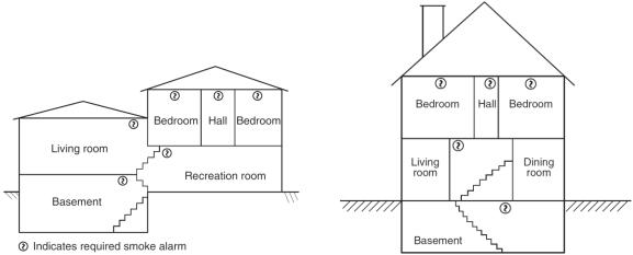
The National Fire Protection Association (NFPA) is the world's leading advocate of fire prevention and issues standards adopted by most municipal governments. NFPA standard 72 recommends the following:
Where to locate the required smoke alarms. The major threat from fire in a dwelling unit occurs at night when everyone is asleep. Persons in sleeping areas can be threatened by fires in the remainder of the unit; therefore, smoke alarms are best located in each bedroom and between the bedroom areas and the rest of the unit. In dwelling units with more than one-bedroom area or with bedrooms on more than one floor, more than one smoke alarm is required. In addition to smoke alarms outside of the sleeping areas and in each bedroom, NFPA 72 requires the installation of a smoke alarm on each additional level of the dwelling unit, including the basement. The living area smoke alarm should be installed in the living room or near the stairway to the upper level, or in both locations. The basement smoke alarm should be installed in close proximity to the stairway leading to the floor above. When installed on an open-joisted ceiling, the smoke alarm should be placed on the bottom of the joists. The smoke alarm should be positioned relative to the stairway so as to intercept smoke coming from a fire in the basement before the smoke enters the stairway.
Are more smoke alarms desirable? The required number of smoke alarms might not provide reliable early warning protection for those areas separated by a door from the areas protected by the required smoke alarms. For this reason, the use of additional smoke alarms for those areas for increased protection is recommended. The additional areas include the basement, bedrooms, dining room, furnace room, utility room, and hallways not protected by the required smoke alarms. The installation of smoke alarms in kitchens, attics (finished or unfinished), or garages is not normally recommended, because these locations occasionally experience conditions that can result in improper operation.
Additional locations. While not required by NFPA, it is recommended that smoke detectors be installed at each end of a hallway that is more than 40 feet long, and in the room where your Blue by ADT equipment is set up. A fire in the room with your Blue by ADT system could prevent the system from reporting the fire or an intrusion.
Please see the diagrams below for example home layouts and recommended smoke detector locations.
4 |
8/7/2020 |
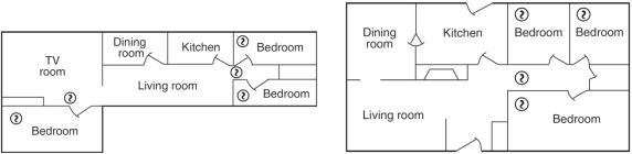
Source: NFPA 72
2.2.Security detection
For best protection against intruders, security sensors should be located at all points where an intruder can potentially enter your home. This includes all first-floor doors and windows, as well as second-floor windows that might be easily reached from a lower roof, trellis, tree, or similar. Motion sensors should be used when it is not practical to use door & window sensors. Motion sensors should also be located in hallways or other areas that an intruder would pass through to reach you or your valuables. In many municipalities, the police dispatchers require 2 sensors to trigger (or a visually verified intrusion) before they will dispatch police. A sensor on an opened door combined with motion detection satisfies this requirement.
In addition to cost and damage from theft, water can cause extensive damage to a home. Water detection sensors (Blue Flood & Temperature Sensors) should be located near any point where water can leak and cause damage. This includes near a washing machine, hot water heater, under sinks, and near toilets.
Blue by ADT systems support two forms of communication, internet and cellular. It is recommended that you enable both forms of communications for redundancy. No network provider or Blue by ADT can always guarantee 100% availability of any network connection, therefore backup provides additional means for communications in the event of a fire.
5 |
8/7/2020 |
3.0Component list
Your Blue by ADT security system was designed for use with the Blue by ADT and approved third party devices below. Your Blue by ADT security system is not approved for use with any other devices. Use of any unapproved or unauthorized devices with your system may cause damage or compromise the performance of your system and affect the limited warranty. The following UL listed devices are supported in a Blue by ADT security system:
-S40LR0-01 Blue Smart Home Hub
-SSH1R0-29 Blue Door & Window Sensors
-SSM1R0-29 Blue Motion Sensor
-SSS1R0-29 Blue Smoke Detector
Other accessories available include:
-SSW1R0-29 Blue Flood & Temperature Sensor
-SKP3R0 Blue Keypad
-SKF3R0-29 Blue Keychain Remote
3.1.Maximum components per system
Smart home hub |
1 |
|
|
Keypad |
250 |
|
|
Door & window sensors |
250 |
|
|
Motion sensors |
250 |
|
|
Smoke detectors |
250 |
|
|
Flood & temperature sensors |
250 |
|
|
Keychain remotes |
250 |
|
|
* The system will support a total combination of 250 sensors of any kind listed in the table.
†Up to 8 simultaneous 2-way conversations
4.0Setting up your system
All Blue by ADT products work together as a system to protect your home. They must be set up in a specific order to work properly. The Blue Smart Home Hub is set up first, followed by the auxiliary sensors and devices.
4.1.Set up the Blue Smart Home Hub
Only 1 Blue Smart Home Hub may be used on a system.
Determine the location
The Blue Smart Home Hub should be placed on a tabletop near an electrical outlet.
6 |
8/7/2020 |
The smart home hub should be located where it cannot be reached by children. Please consider the following when deciding where to locate the smart home hub:
-The smart home hub will require AC power, so an outlet should be available within 6 feet. The outlet must not be controlled by a switch, and must provide continuous power.
-The smart home hub receives all sensor events wirelessly, so a more central location is preferred in your home (depending on size). If you locate the smart home hub in a far corner of the house, it may not be able to receive signals from the opposite side of your home. You can locate the smart home hub in a first or second floor room. In general, basement locations are not as good for wireless coverage.
-Open air range of the wireless sensors to the smart home hub is in excess of 200m. Due to variations in building construction and other conditions, the actual range may be significantly less. Manufacturer’s published range should be used for comparative purposes only.
-The smart home hub must communicate to Blue by ADT using Wi-Fi or LTE cellular service (or a combination). The smart home hub must have a good Wi-Fi signal to your router. Please see the notes below on Wi-Fi signal coverage in a home.
-If you intend to use the LTE cellular capability of the smart home hub, the device will need to receive a cellular signal. In most parts of the country, AT&T is the preferred carrier for the LTE cellular signal. The smart home hub includes an internal cellular antenna.
-The smart home hub includes a loud piezo siren. You will want to make sure the device is located in a place where you can hear the siren.
-The top of the smart home hub contains a built-in keypad for arming and turning off your security system. Do not place anything on top of your smart home hub, which could accidentally press buttons.
-The smart home hub should not be mounted in location subject to temperatures over 120 F (49°C) or below 32 F (0C) for any extended period of time. This will degrade the battery life.
Note: Please keep in mind that when finding a place to position your smart home hub, it will need to be free from metal objects and appliances that generate heat. Avoid setting the device directly on or near any major appliances, kitchen appliances, heaters, entertainment consoles, cable boxes, internet routers, televisions, and stereos.
Placing the Blue Smart Home Hub
The Blue Smart Home Hub may be placed vertically on a shelf or a table top. The smart home hub includes a non-skid bottom that helps prevent the device from moving.
7 |
8/7/2020 |

Power up the Blue Smart Home Hub
Once you have placed the Blue Smart Home Hub, you can connect AC power. Use only the power supply model F18L10 supplied with your smart home hub. Do not use any other adapters. Insert the power adapter plug fully into the jack on the bottom of the smart home hub. Plug the power adapter into the wall outlet. The power adapter LED should illuminate green if power is available. The smart home hub was shipped to you in a deep sleep state. The battery is connected, but all of the circuits are turned off. When you apply AC power for the first time, the smart home hub will boot (in a similar fashion to your computer). This boot process takes about 30 seconds. Please see the LED descriptions if you want to monitor the completion of boot mode.
Connect power adapter
•Do not use an electrical outlet that is controlled by a switch or part of a ground fault circuit interrupter (GFCI) that could switch power off.
•Insert the power adapter plug fully into the jack on the bottom of the smart home hub. Plug the power adapter into the wall outlet.
•Place the power adapter cord so that it does not create a tripping hazard, or become pinched and create an electrical hazard.
•In the event that AC power is lost, the power adapter LED indicator will go dark, the LED on top of the unit will flash yellow, and the unit will chirp once.
•In the event that the power adapter plug is disconnected from the bottom of the smart home hub, the LED on top of the unit will flash yellow, and the unit will chirp once.
Setup and activation
1.While your smart home hub is starting up, if you have not done so already, download the iOS or Android app by visiting www.BluebyADT.com/apps. Open the app to create an account or log in to an existing account.
2.Follow the in-app setup instructions to connect your Blue Smart Home Hub to your home’s Wi-Fi
network.
Note: Make sure Bluetooth is ON on your mobile device. Your device will need to pair over Bluetooth to your smart home hub for setup.
8 |
8/7/2020 |
3.After activating your smart home hub, proceed with the in-app guide for setting up any sensors, devices, and cameras.
Note: It is important to set up professional monitoring since it helps to protect your home in the event of burglary and fire. Enrolling in professional monitoring ensures that the monitoring center will contact you and dispatch emergency authorities if needed.
WARNING: Only use dedicated always-on broadband internet communications. Do not use dial-up type internet connections that are not always available. Your Blue by ADT security system sends regular “heartbeat” messages to the Blue by ADT servers every 5 to 60 seconds. In addition, during an alarm condition, relying on dial-up connections is not always reliable or assured.
Battery backup for internet router
While your Blue by ADT security system includes battery backup, communications to the monitoring center may still be disrupted in the event of power outage if your router and internet communications do not also have battery backup. You must provide at least 8 hours of battery backup for any equipment (such as a router, switch, or broadband internet modem) used for communications by your Blue by ADT security system to the internet.
Red button on bottom of unit. A momentary press of this button will cause the smart home hub to reboot. This is not a common need and it is recommended that you do not press this button unless a Blue by ADT customer service representative has instructed you to press the button.
Arming your security system:
Blue by ADT provides a variety of options for arming and disarming your system. The Blue by ADT Smart Home Hub includes a keypad that is built into the top of your device for convenient control. Depending on your needs, you may choose one of three different arming modes:
-STAY: Press the Stay button and then enter your User Code to arm in stay mode. o This is used when you are home, entry and exit delays are ON, and motion
sensors are OFF.
-AWAY: Press the Away button and then enter your User Code to arm in away mode. o This is used when no one is home, entry and exit delays are ON, and motion
sensors are ON.
-NIGHT: Press the Night button and then enter your User Code to arm in night mode. o This is used when you’re in for the night, entry and exit delays are OFF, and
motion sensors are OFF.
-OFF: Press OFF and then enter your User Code to disarm your security system.
Note: By design, the exit and entry delays give you enough time to leave or enter your home without setting off a false alarm.
TIP: Make sure all windows and doors are closed before arming the system. If a sensor is open when you are trying to arm the system, you will be prompted to bypass the sensor. You can either close the door or window and try to arm again or bypass the sensor so it won’t be monitored until the next time the system is armed.
Your smart home hub includes a panic button to be used in case of an emergency inside your home. This panic button will immediately notify the monitoring center to automatically dispatch emergency services to help you.
9 |
8/7/2020 |
To trigger the panic button:
• Smart home hub: Press and hold the star (*) and pound (#) buttons at the same time for two seconds. This action will trigger a panic alarm.
Press Off to cancel the Panic alarm siren locally on your smart home hub.
Note: If monitored, once a panic alarm is triggered, you cannot cancel emergency services from being dispatched.
•Duress code: There is also an option to set up a unique duress code (different from your User Codes). Use this code when you feel threatened by someone forcing you to disarm from inside your home. When you enter the code, the alarm will not sound. A special duress message is sent to the monitoring center, and emergency services will respond appropriately.
•To create a duress code, select Menu > Users > + to Add, and select Duress User. Create a Duress User with a unique 4-digit duress code and then press Add User.
Note: The panic button and duress code should only be used in an emergency. There is no option to cancel dispatch if you are not in an emergency. Your local municipality and police department will treat this as a false alarm.
Users
Blue by ADT allows for multiple User Codes, which will enable you to keep track of who arms and disarms your system.
•Master User Code: You will only have one 4-digit Master User Code, which gives you complete access to your entire system. Protect this code, and do not share it with others.
•Users: Invite your trusted friends and family and keep track of who arms and disarms your system. Users will be invited via email and set their login password, security question, and can manage their notifications under My profile. As the Master User, you may invite any of the following user types to your system:
•Admin Users get full access to all platforms and functionalities except billing.
•Standard Users have access to monitoring, controlling, and limited settings management.
•Basic Users can only arm/disarm.
•Duress User is a code to disarm the system and notify the monitoring center. You may only have one duress code, which is shared by all, to trigger a duress alert to the monitoring center.
Learn more about Users by visiting BluebyADT.com/support
What to do in the event of an alarm:
Useful knowledge:
What is a User Code? It’s your 4-digit PIN used to disarm your system.
What is a Monitoring Passcode? This passcode is a phrase given verbally to the monitoring center to verify that you are the account holder. In the event of an
10 |
8/7/2020 |
alarm, you must provide it to prevent dispatch or also to discuss any information with the monitoring center.
When your alarm is sounding, there are a few options for you to choose, depending on the scenario:
•If it is a false alarm triggered by you, a loved one, or by accident, you have 30 seconds to
Disarm the alarm by entering your User Code. Doing this will cancel the alarm and return the system to normal with no further action.
•If it is a false alarm and you do not enter a User Code within 30 seconds, the monitoring center will call the primary contact. If that person gives the correct monitoring passcode to the dispatcher, the false alarm is canceled.
•If the alarm sounds in a true emergency, then the alarm will continue to sound, and the monitoring center will be notified after 30 seconds. The primary contact will receive a call, provide the monitoring passcode, and can request dispatch of emergency services to your home.
•If the primary contact is unavailable or cannot provide the dispatch with the monitoring passcode, the dispatcher will continue calling the secondary contact and any courtesy contact until someone has the correct monitoring passcode.
•If the incorrect monitoring passcode is provided or no contact can be reached, the monitoring center will contact the authorities.
Make sure you have a family emergency escape plan that specifies where to meet and what to do in case of an emergency.
Blue Smart Home Hub settings
•To manage settings of your smart home hub, launch your Blue by ADT app or log in to the web portal. From the app/web portal, you can manage the LED light settings as well as audio settings for turning on or off various chimes and tones. If you do not want to have the panic button enabled, you can also disable the panic button feature if desired. Then the panic button is enabled by default.
•Learn more by visiting www.BluebyADT.com/support
Cameras, sensors, and devices
•Follow the in-app guide for setting up the sensors and devices that come with your initial system purchase. If you purchase additional sensors, devices, or cameras after initial setup, you can easily pair those to your system by launching the app go to into Menu > Devices and select + Add.
•You can expand your security system at any time. Order online under Shop on your web portal or contact Blue by ADT to purchase additional devices at 877-
987-4435
11 |
8/7/2020 |

4.1.1. Z-Wave™ statement
The Blue Smart Home Hub is a Z-Wave Plus™ Product supporting the S2 Security Protocol with numerous capabilities described below.
This product can be operated in any Z-Wave network with other Z-Wave certified devices from other manufacturers. All mains operated nodes within the network will act as repeaters regardless of vendor to increase reliability of the network.
SmartStart enabled products can be added into a Z-Wave network by scanning the Z-Wave QR Code present on the product with a controller providing SmartStart inclusion. No further action is required and the SmartStart product will be added automatically within 10 minutes of being switched on in the network vicinity. To access the SmartStart Provisioning list, go to Settings > Devices > Go to your smart home hub > Select advanced settings and then clicking SmartStart Provisioning. From there you can add a device by selecting “+” and then either selecting Manually or Scan QR Code and follow the prompts. Once a SmartStart device has been successfully added its DSK (Device Specific Key) and status will show up on the SmartStart Provisioning screen. To remove a SmartStart provisioned device from the screen, swipe it left and you will be asked to Confirm or Cancel the request for removalclick Smart.
The DSK (Device Specific Key) can be accessed by going to Settings > Devices > Going to your smart home hub > Selecting advanced settings and then clicking Z-Wave Learn Mode. The full DSK will be displayed.
Your system supports the use of Z-Wave lights, locks, thermostats, and garage door controllers. To learn more about how to add the devices to your system, control them, and what is supported, please visit www.BluebyADT.com/support and explore our Support Center articles. A summary is listed below.
Adding a device:
To add a Z-Wave device, go to Settings > Devices > Click on the add button and then select the type of device. The smart home hub will then go into inclusion mode and you will be prompted
12 |
8/7/2020 |
to follow your manufacturer’s instructions to put the device into inclusion mode. Once the device is added you will hear a confirmation beep from your smart home hub and you will be brought to a screen to name the device and to choose an icon.
Some Z-Wave devices may support secure adding also known as ‘S2.’ S2 devices encrypt their communication with the smart home hub for added security. These devices can be added using the process described above, but once the device has been discovered, you will be prompted to enter a PIN code provided on the device label to complete the process. After the device has been successfully added, it will operate like any other Z-Wave device. If secure add fails, the device may still add, but in an unsecured mode, and you may be prompted to delete and reinstall the device to ensure it is properly secured.
Note: Not all Z-Wave device types may be supported by the system. If you choose to add a device that is unsupported, it will come into the system as unknown and be located in the lights and appliances cards.
Controlling a device:
Once a Z-Wave device has been added to the Blue Smart Home Hub, it can be controlled using the home automation cards on the main screen of the iOS, Android, or web applications. All devices can be issued basic on/off commands, but devices which support other features will have additional control options on their card.
Lights |
Turn the light on and off and change the brightness for dimmable switches. |
|
Locks |
Lock and unlock the lock. |
|
Garage doors |
Open and close your garage door. |
|
Thermostats |
View your current temperature and mode, adjust your temperature settings, |
|
change the heating and cooling mode, and change the fan mode. |
||
|
||
Unknown |
Any device that is added to the system but is not recognized as a fully |
|
devices |
supported device will only have basic on/off control. |
Sensors:
The system does not currently support Z-Wave sensors. It is recommended that you use DECT/ULE sensors that can be purchased in the Blue by ADT store instead.
Association Group information:
This product supports Association Group 1 (Lifeline) with the maximum of 5 nodes. This product will send CC DEVICE_RESET_LOCALLY to the lifeline before performing default factory reset.
Removing a device:
To remove a device, go to Settings > Devices and choose your device. You can then delete it by clicking remove and following your manufacturer’s directions to put the device into exclusion mode. If a device is not on the network, you may fail the remove and then be prompted to remove the failed device. This will remove the device from the network without it being present.
13 |
8/7/2020 |
If you would like to add your device to another system, then you will need to reset the device per the manufacturer’s instructions. You can use the general exclusion for resetting devices as well under Settings > Devices > Go to your smart home hub > Select advanced settings, and then click General Exclusion.
Removing a failed node:
If you are attempting to remove a device that is no longer active in the Z-Wave network, you can instruct the smart home hub to remove the device. Navigate to the advanced Z-Wave settings page for the failed device and press “Remove Failed Device”. The smart home hub will proceed to remove the device from the Z-Wave network. Note: If your device comes back online after it has been removed via Removed Failed Device, you will need to reset your device in order to readd it. Use “General Device Exclusion” to do this.
Replacing a device:
To replace a device, go to Settings > Devices > Choose Your Device and then select Replace Device. You will first be prompted to click on the device you are replacing. If it is not on the network you will be prompted to remove the failed device. After the first device is removed, you will be prompted to add your new device by following the manufacturer’s instructions to add a device. Once the replace is confirmed, then your device will then work as your other device did with rules. If you attempt to replace a device with a different type of device, for example replacing a light with a lock, then your rules will no longer work for that device.
Adding your smart home hub to another network:
If you would like to add the smart home hub into another Z-Wave network, you must first delete all Z-Wave devices from the smart home hub before proceeding. Once all devices have been deleted, follow the instructions on the other controller to put it into add mode. Once the other Z- Wave controller is in add mode, you can place the smart home hub into learn mode by navigating to Settings > Devices > Choosing your smart home hub > Opening Advanced Options.
From this menu, select Z-Wave Learn Mode to put the smart home hub into learn mode. Follow the instructions on the other controller to complete the add process. Once the add is complete, the smart home hub will request a copy of the other Z-Wave network configuration, and the network devices will appear on the Blue by ADT iOS, Android, and web applications.
When the smart home hub is included in another Z-Wave network, it will ignore Basic Z-Wave commands that are sent to it.
Copying your Z-Wave network information to another controller:
If you would like to copy your network information to another controller, you must add the controller to the Z-Wave network using the normal device add process. Once the controller has been successfully added to the Z-Wave network, all network configuration will be automatically transferred to the new controller.
Resetting your Z-Wave network:
If this controller is the primary controller for your network, resetting it will result in the nodes in your network being orphaned and it will be necessary after the reset to exclude and re-include all of the nodes in the network. If this controller is being used as a secondary controller in the
14 |
8/7/2020 |
network, use this procedure to reset this controller only in the event that the network primary controller is missing or otherwise inoperable. In order to factory reset your Z-Wave network, go to Settings > Devices > Choose your smart home hub > Open Advanced Settings and then select Z-Wave Reset Controller. After a few seconds, the smart home hub will beep to indicate that your Z-Wave network has been reset. Any devices which were part of your Z-Wave network will need to be reset before they can be re-added. Use the Z-Wave General Exclusion menu under Settings > Devices > Choose your smart home hub > Open Advanced Settings to do this.
Interoperability with Z-Wave devices
This product can be operated in any Z-Wave network with other Z-Wave certified devices from other manufacturers. All non-battery-operated nodes within the network will act as repeaters regardless of vendor to increase the reliability of the network.
Functional overview
This device behaves as static controller based on the Z-Wave Controller Library. It controls devices using the following Z-Wave Command Classes:
Ver |
Non-secured CC |
Ver |
Secure CC |
sion |
sion |
||
2 |
COMMAND_CLASS_ZWAV |
3 |
COMMAND_CLASS_NETWORK_MANAGEMEN |
|
EPLUS_INFO |
|
T_ INCLUSION |
2 |
COMMAND_CLASS_TRANS |
2 |
COMMAND_CLASS_NETWORK_MANAGEMEN |
|
PORT_SERVICE |
|
T_BASIC |
1 |
COMMAND_CLASS_CRC_1 |
2 |
COMMAND_CLASS_NETWORK_MANAGEMEN |
|
6_ENCAP |
|
T_PROXY |
1 |
COMMAND_CLASS_APPLI |
1 |
COMMAND_CLASS_ASSOCIATION_GRP_INFO |
|
CATION_STATUS |
|
|
1 |
COMMAND_CLASS_APPLI |
1 |
COMMAND_CLASS_DEVICE_RESET_LOCALL |
|
CATION_CAPABILITY |
|
Y |
1 |
COMMAND_CLASS_SECUR |
1 |
COMMAND_CLASS_NETWORK_MANAGEMEN |
|
ITY_2 |
|
T_ INSTALLATION_MAINTENANCE |
1 |
COMMAND_CLASS_SECUR |
2 |
COMMAND_CLASS_MANUFACTURER_SPECIF |
|
ITY |
|
IC |
1 |
COMMAND_CLASS_INCLU |
1 |
COMMAND_CLASS_POWERLEVEL |
|
SION_CONTROLLER |
|
|
1 |
COMMAND_CLASS_SUPER |
1 |
COMMAND_CLASS_NODE_PROVISIONING |
|
VISION |
|
|
|
|
5 |
COMMAND_CLASS_FIRMWARE_UPDATE_MD |
|
|
2 |
COMMAND_CLASS_ASSOCIATION |
|
|
2 |
COMMAND_CLASS_VERSION |
This product controls devices with Basic Command Class using values 0 for OFF and 255 for ON. The device does not implement supports for receiving Basic Command Class.
15 |
8/7/2020 |
DESCRIPTION OF CONTROLLED COMMANDS AND FUNCTIONS
|
Controlled Command Classes |
|
|
Functions |
How |
|
|
|
|
|
|
|
|
|
|
|
|
|
Include devices that support this CC. During configuring and interviewing, this device will |
|
|
COMMAND_CLASS_MULTI_CHANNEL_ASSOCIATION |
|
|
To establish Lifeline configuration during Inclusion |
attempt to configure/query association information using this CC. |
|
|
|
|
|
|
|
|
|
|
|
|
|
Add a sleeping device. When the sleeping device checks in, this product will send Wake up |
|
|
COMMAND_CLASS_WAKE_UP |
|
|
To set wake up interval and send wake up no more |
no more to the device. |
|
|
|
|
|
|
|
|
|
|
|
|
|
Add a power strip that supports multi-channel. Using the User App, turn on or off the |
|
|
COMMAND_CLASS_MULTI_CHANNEL |
|
|
To control multi-channel endpoints |
endpoints. |
|
|
|
|
|
|
|
|
|
|
|
|
To control Entry Control devices such as Garage |
|
|
|
COMMAND_CLASSS_BARRIER_OPERATOR |
|
|
door controller |
Include a garage controller. On the User App, open/close garage controller. |
|
|
|
|
|
|
|
|
|
|
|
|
To control Unknown devices or Device that only |
|
|
|
COMMAND_CLASS_BASIC |
|
|
support BASIC CC |
Include an unknown device. On the User App, turn on or off unknown devices. |
|
|
|
|
|
|
|
|
|
COMMAND_CLASS_SWITCH_BINARY |
|
|
To control Binary Switch Devices |
Include a binary switch device. On the User App, turn on or off binary switch device. |
|
|
|
|
|
|
|
|
|
COMMAND_CLASS_DOOR_LOCK |
|
|
To Control Lock device |
Include a lock. On the User App, lock or unlock the device. |
|
|
|
|
|
|
|
|
|
|
|
|
|
Add a device that support metering information. See that metering is reported correctly on |
|
|
COMMAND_CLASS_METER |
|
|
To report metering information |
the User App. |
|
|
|
|
|
|
|
|
|
|
|
|
|
Add a thermostat that report temperature as multi-level sensor report. See that the |
|
|
COMMAND_CLASS_SENSOR_MULTILEVEL |
|
|
To control multi-level sensor devices |
temperature is reported correctly on the User App. |
|
|
|
|
|
|
|
|
|
COMMAND_CLASS_SWITCH_MULTILEVEL |
|
|
To control multi-level switch devices |
Add a dimmer that support this CC. Control the dimming levels. |
|
|
|
|
|
|
|
|
|
COMMAND_CLASS_NOTIFICATION_V3 |
|
|
To process status from Lock |
Add a lock. Manually change the lock. See that the lock’ |
|
|
|
|
|
|
|
|
|
COMMAND_CLASS_THERMOSTAT_FAN_MODE |
|
|
To control thermostat |
Add a thermostat. On the User App, change the thermostat fan mode. |
|
|
|
|
|
|
|
|
|
|
|
|
|
Add a thermostat. On the User App, change the fan mode. See that the fan state is display |
|
|
COMMAND_CLASS_THERMOSTAT_FAN_STATE |
|
|
To display thermostat status |
appropriately. |
|
|
|
|
|
|
|
|
|
COMMAND_CLASS_THERMOSTAT_MODE |
|
|
To control thermostat |
Add a thermostat. On the User App, change the thermostat operating mode. |
|
|
|
|
|
|
|
|
|
|
|
|
|
Add a thermostat. On the User App, change the thermostat operating mode. See that the |
|
|
COMMAND_CLASS_THERMOSTAT_OPERATING_STATE |
|
|
To display thermostats status. |
operating state is displaying appropriately. |
|
|
|
|
|
|
|
|
|
COMMAND_CLASS_THERMOSTAT_SETPOINT |
|
|
To control thermostat |
Add a thermostat. On the User App, change the setpoints. |
|
|
|
|
|
|
|
|
|
|
|
|
|
Include devices that support this CC. During configuring and interviewing, this device will |
|
|
COMMAND_CLASS_ASSOCIATION |
|
|
To establish Lifeline configuration during inclusion |
attempt to configure/query association information using this CC. |
|
|
|
|
|
|
||
|
|
|
|
|
|
|
|
|
|
|
|
Include a device that support metering information. See that this product attempt to request |
|
|
COMMAND_CLASS_VERSION |
|
|
To query the supported version of a Command Class |
the METERING CC’s supported. |
version |
|
|
|
|
|
|
|
|
|
|
|
|
Include the device. Observe that this product requests the included device’s m |
|
|
COMMAND_CLASS_MANUFACTURER_SPECIFIC |
|
|
To interview the device’s manufacturin |
information. |
|
|
|
|
|
|
|
|
|
COMMAND_CLASS_NETWORK_MANAGEMENT_BASIC |
|
|
Use to reset controller |
On the User app, reset the controller. |
|
|
|
|
|
|
|
|
|
|
|
|
|
Add a device. This product will request the node’s cach |
|
|
COMMAND_CLASS_NETWORK_MANAGEMENT_PROXY |
|
|
Use to request node’s cache i |
the supported device type using its basic, generic and specific type in the cache report. |
|
|
|
|
|
|
|
|
|
COMMAND_CLASS_NETWORK_MANAGEMENT_INCLUSION |
|
|
To assign return route |
Add a device and observe that this product will configur |
|
|
|
|
|
|
|
|
|
|
|
|
To ask a receiving node to perform specific steps in |
When this product is an inclusion controller, if user requests to start the inclusion process, |
|
|
COMMAND_CLASS_INCLUSION_CONTROLLER |
|
|
the inclusion/bootstrapping |
this product will request the SIS to perform the inclusion bootstrapping process. |
|
|
|
|
process |
|
|
|
|
|
|
|
|
|
|
|
|
|
|
|
|
|
|
COMMAND_CLASS_SECURITY_2 |
|
|
To encapsulate secure commands |
Add an S2 capable device. |
|
|
|
|
|
|
|
|
|
COMMAND_CLASS_SECURITY |
|
|
To encapsulate secure commands |
Add an S0 capable device. |
|
|
|
|
|
|
|
|
|
|
|
|
|
Add a Z-Wave Plus device. Observe using a Z-Wave packet sniffer, this device will request |
|
|
COMMAND_CLASS_ZWAVEPLUS_INFO |
|
|
To request Node’sZ-Wave Plus info |
the included Zdevice’s-Wave Plus information. |
|
|
|
|
|
|
|
|
|
|
|
|
|
Add a device that support this CC. Observe using a sniffer that this product uses |
|
|
COMMAND_CLASS_TRANSPORT_SERVICE |
|
|
To encapsulate commands |
encapsulation when communicating with the device. |
|
|
|
|
|
|
|
|
|
|
|
|
|
Add a device that support this CC. Observe using a sniffer that this product uses |
|
|
COMMAND_CLASS_CRC_16_ENCAP |
|
|
To encapsulate commands |
encapsulation when communicating with the device. |
|
|
|
|
|
|
|
|
16 |
8/7/2020 |
 Loading...