

Page 1
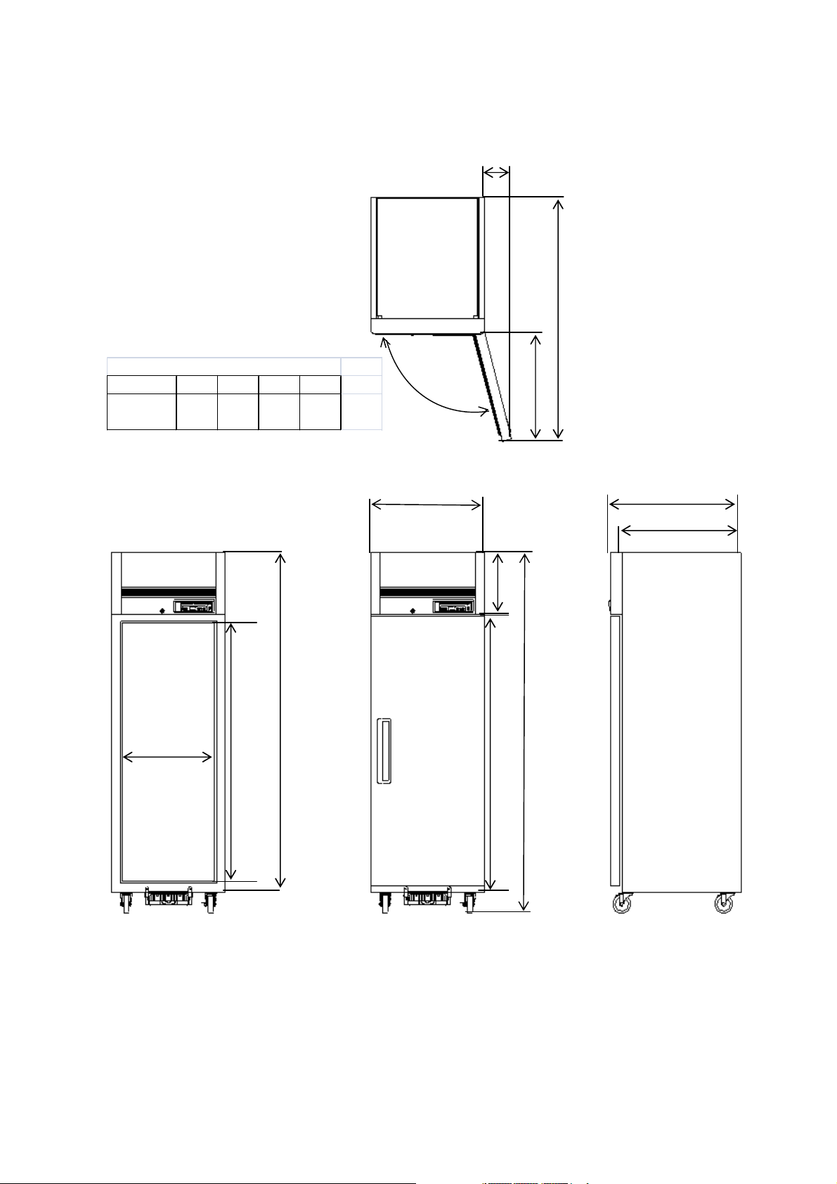
B. Dimensions
1. BSR23T(LRT-23S), BSF23T(LFT-23S)
MODEL
LRT-23S
LFT-23S
1403
(55.2i n)
mm (in)
ABCD
163
617
(6.4in)
(24.7in)
105˚
B
A
D
C
551 (21.7in)
(INSIDE)
1483
(58.4in)
1954
(76.9in)
681 (26.8in)
1549
(61in)
786 (30.9in)
717 (28.2in)
358
(14in)
2077.6
(81.8in)
Page 1
Page 2
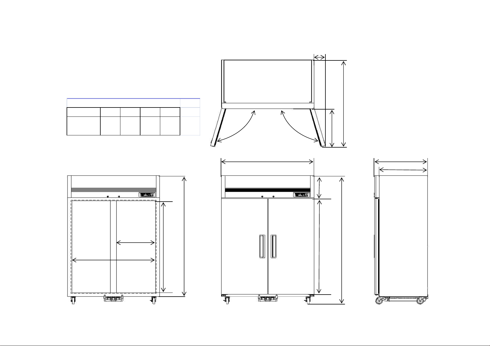
B. Dimensions
1. BSR49T(LRT-49D), BSF49T(LFT-49D)
B
MODEL
LRT-49D
LFT-49D
mm (in)
ABCD
1403
(55.2i n)
163
(6.4in )
573 (22.5in)
(INSIDE)
1240 (48.8in)
(INSIDE)
617
(24.7i n)
105˚
1483
(58.4in)`
1954
(76.9in)
A
D
1370 (53.9in)
D
C
786 (30.9in)
717 (28.2in)
358
(14in)
2077.6
(81.8in)
1549
(61in)
Page 2
Page 3
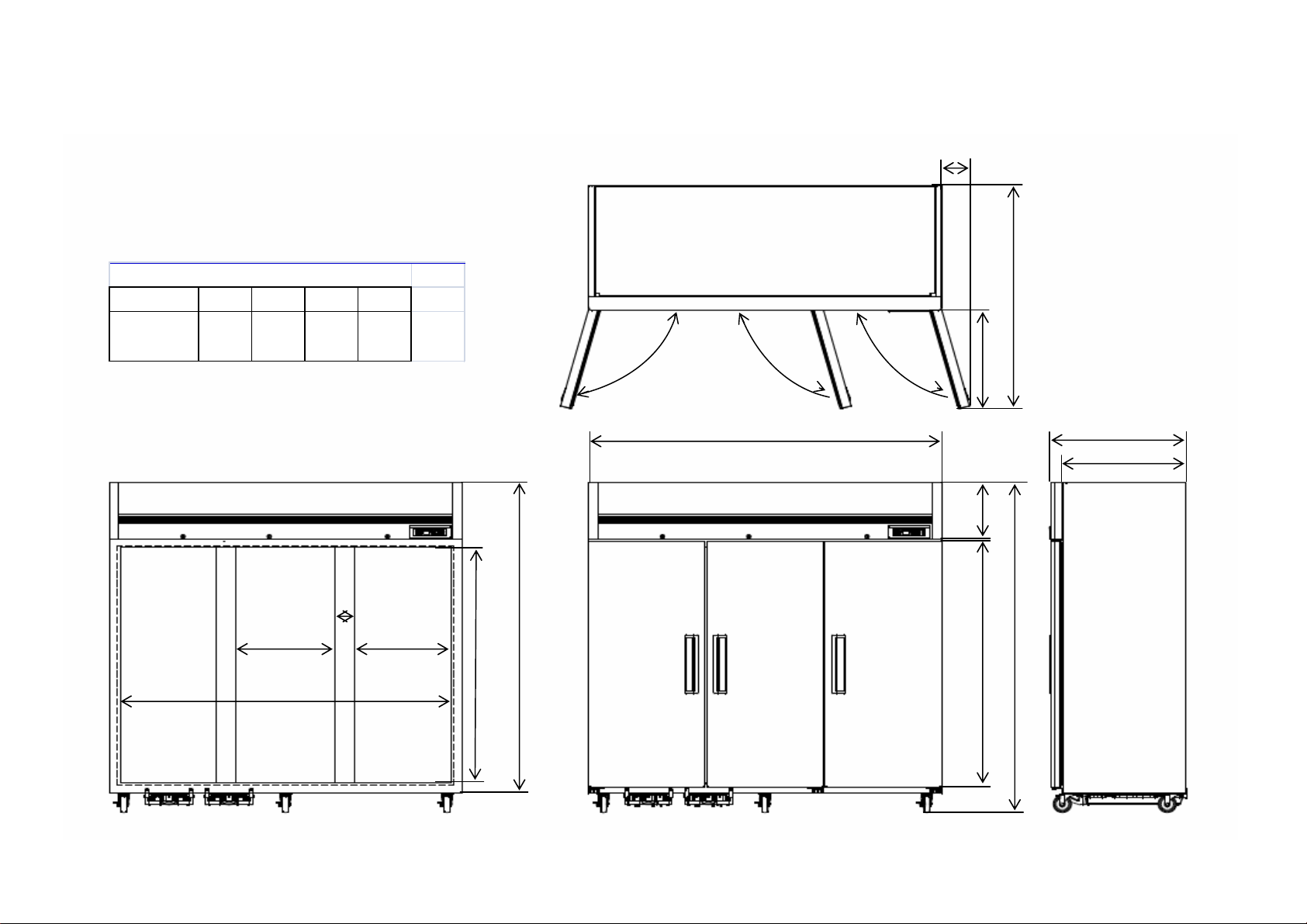
B. Dimensions
1. BSR72T(LRT-72T), BSF72T(LFT-72T)
mm (in)
MODEL
LRT-72T
LFT-72T
ABCD
1403
(55.2i n)
163
(6.4in)
617
(24.7in)
105˚
B
A
D
D D
C
114 (4.5in)
566 (22.3in)
(INSIDE)
1926 (75.8in)
(INSIDE)
566 (22.3in)
(INSIDE)
1483
(58.4in)`
195
4
(76.
9in)
Page 3
2060 (81.1in)
358
(14i
n)
154
9
(61i
n)
786 (30.9in)
717 (28.2in)
207
7.6
(81.
8in)
Page 4
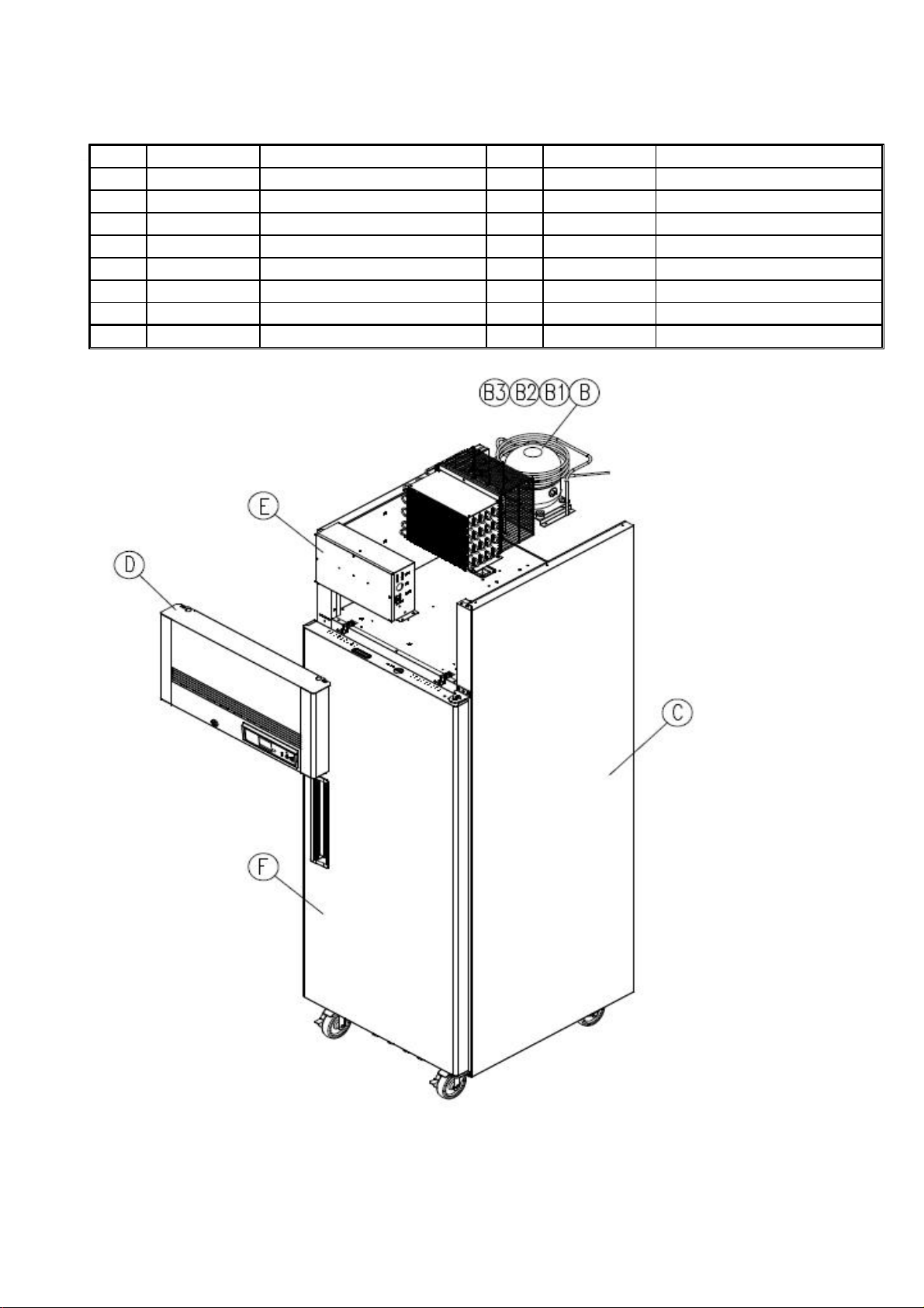
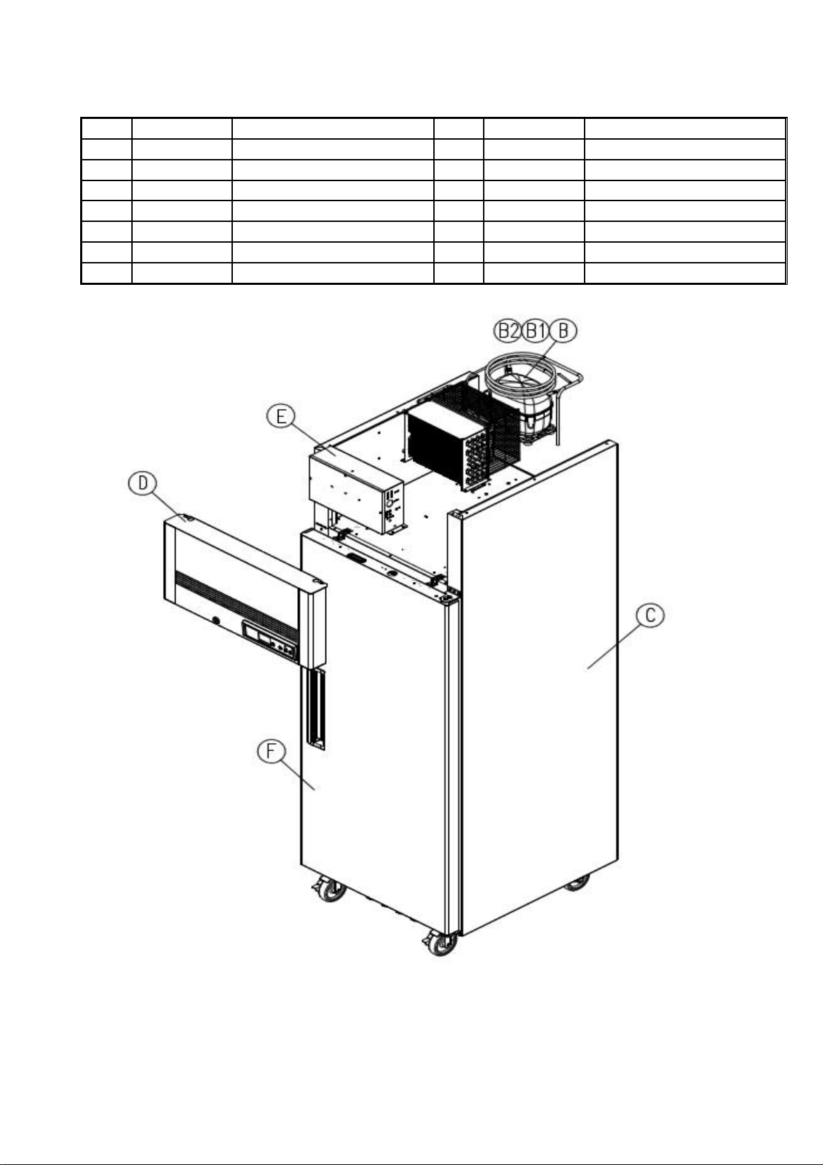
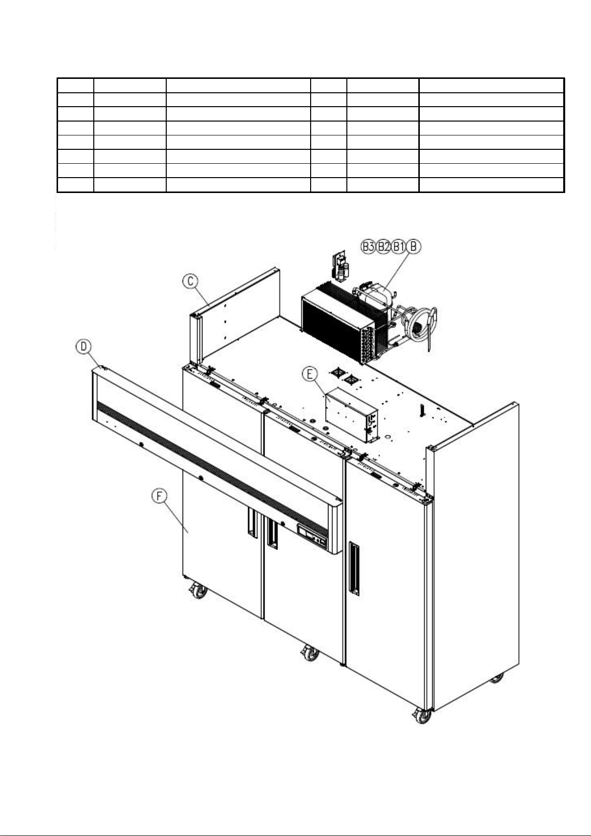
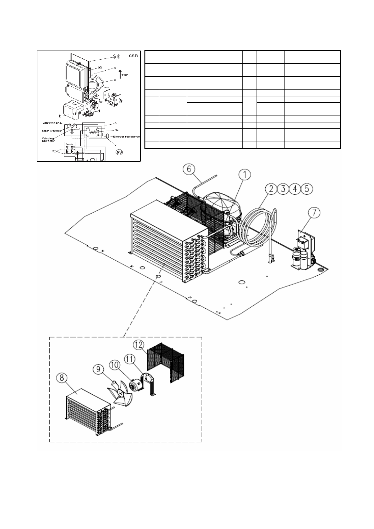
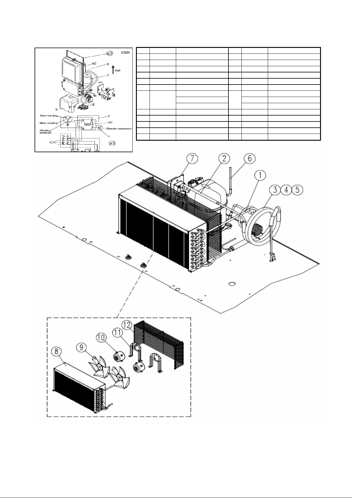
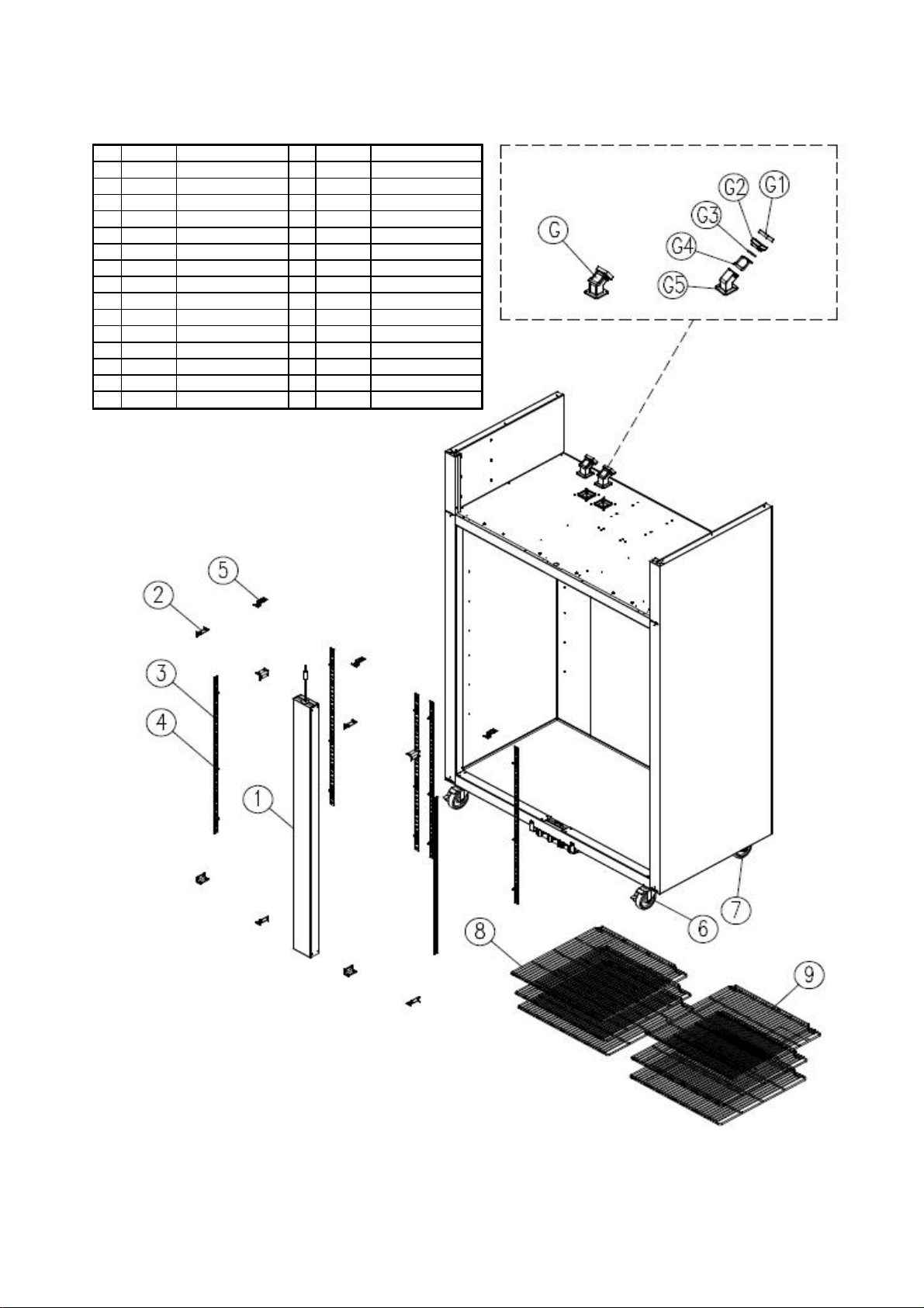
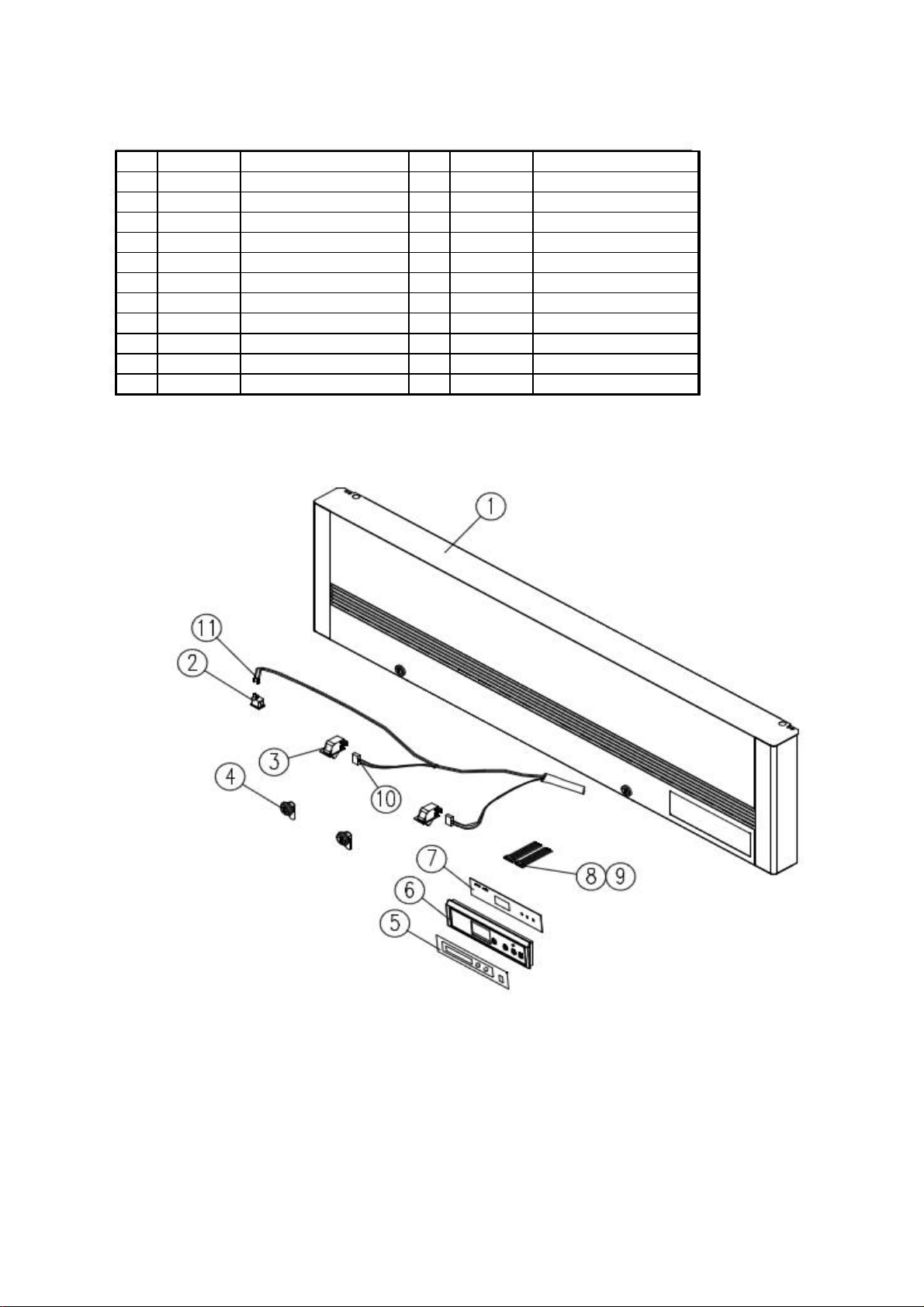
A. Main Assembly
4B24
Ass'
M
0
103-950
Mai
8249-630
ill A
8582-510
3243-040
GIT1.6x135x236
3884-030
G
NRN
k
439-110
C
SK1A1C-L2W,115V/60H
3004-270
C
1. BSR23T
NO. Qty
M odel Code Description M aterial Spec
B1
B1
B3 1
C1
D1
E1
F1
R7
R
R
R
R
R
R7
ompressor ompressor Bolt-
rommet Comp
Reinf Comp
Body Assembly-Top Gr
n PCB Box - -
y Door RH T
ssembly--
--R817A-05
M6x30Y ∮10
R-Rubber, Blac
z
Page 4
Page 5
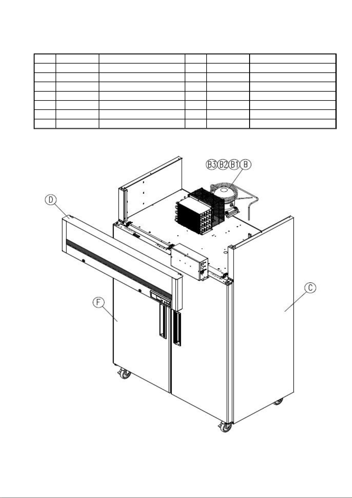
A. Main Assembly
y
4B24
E
3004-270
0
Ass'y
M
Mai
dy A
bly
p Grill A
bly
3884-030
G
p
NRN
k
Comp
p
439-640
Comp
SC1 2CLX2,115V/60H
8582-510
8249-630
103-960
2. BSF23T
NO. Qt
Model Code
B1
B1
C1
D1
F1
R7
R
R
R
R
R7
R817A-05
rommet Com
Bo
To
Descri
ressor ressor Bolt-
ssem
n PCB Box
Door RH T
tion Material Spec
M6x30Y ∮10
R-Rubber, Blac
--
ssem
1
--
--
--
z
Page 5
Page 6
A. Main Assembly
4B24
E
103-970
Mai
8249-640
ill A
bly
8582-450
3243-040
p
GIT1.6x135x236
G
p
NRN
k
439-110
Comp
SK1A 1C-L2W,115V/60H
p
3004-270
Comp
3884-030
3. BSR49T
NO. Qty
M odel Code Descri
B1
B1
R7
R
R
B3 1
C1
D1
R
R
R
Reinf Com
Body Assembly-Top Gr
R7
ressor ressor Bolt
rommet Com
n PCB Box - -
tion Material Spec
-
M6x30Y ∮10
R-Rubber, Blac
ssem
--
1
z
Page 6
Page 7
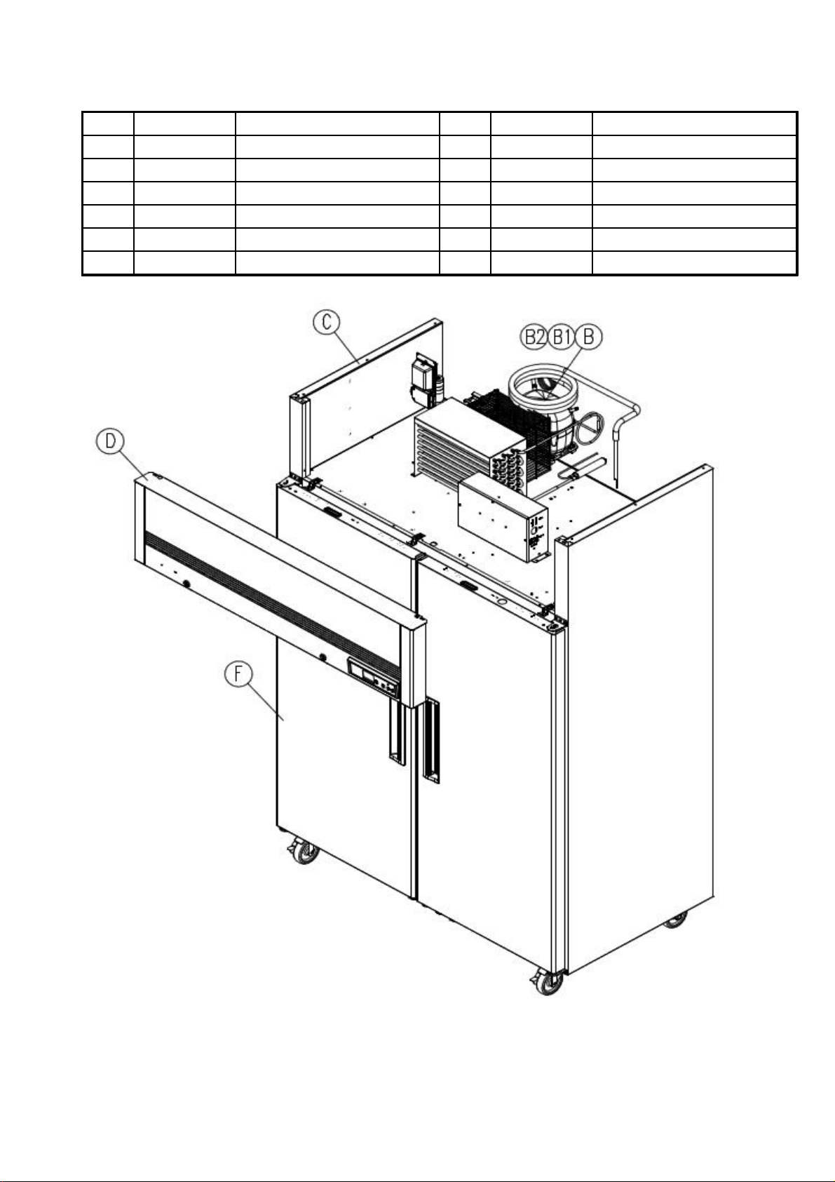
A. Main Assembly
4B24
E
N
k
8249-640
ill A
3884-030
G
N
3004-270
C
V
4. BSF49T
NO. Qty
M odel Code Description M aterial Spec
B1
B1
C1
D1
R7439-600 Compressor - SC18CLX2, 115
R
R
R8582-450
R
R7103-980 M ain PCB Box - -
ompressor Bolt-
rommet Comp
R
M6x30Y ∮10
R-Rubber, Blac
Body A ssembly - Top Gr
ssembly-
1
60Hz
Page 7
Page 8
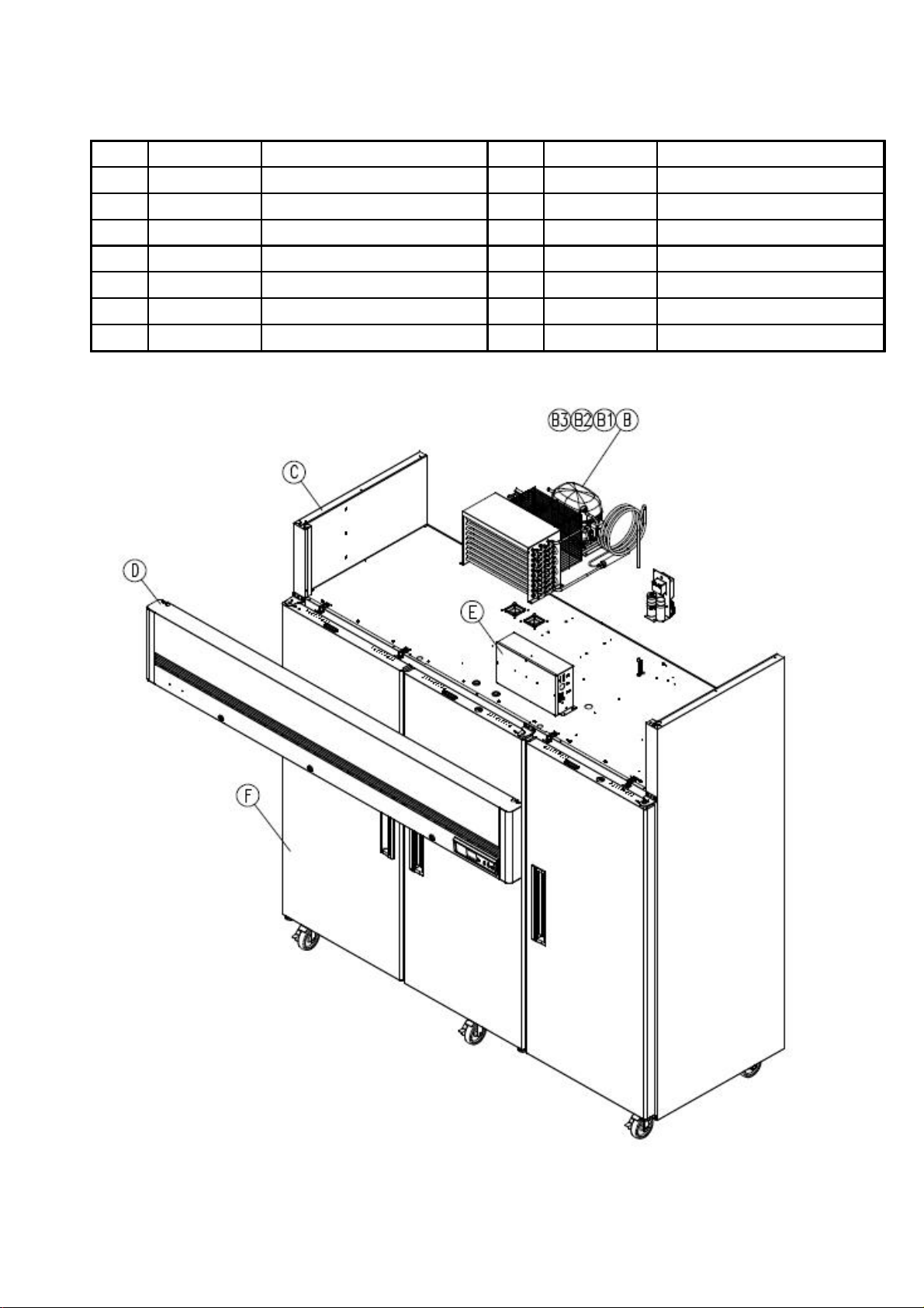
A. Main Assembly
4B24
818A-030
ill A
829A-020
Ass'y C
3243-040
p
GIT1.6x135x236
844A-080
3004-270
Comp
3884-030
G
p
NRN
k
439-600
Comp
SC18CLX2, 115V60H
5. BSR72T
NO. Qty
M odel Code Description Material Spec
B1
B1
R7
R
R
B3 1
C1
D1
E1
R
R
R
R
Reinf Com
Body Assembly-Top Gr
ressor ressor Bolt-
rommet Com
M6x30Y ∮10
R-Rubber, Blac
ssembly--
ontrol Box T72R--
z
Page 8
Page 9
A. Main Assembly
4B24
E
818A-030
ill A
bly
829A-010
Ass'y C
dy A
14A-020
C
GS26CLX
3884-030
G
3004-270
C
NRN
k
3243-040
GIT1.6x135x236
844A-070
6. BSF72T
NO. Qty
M odel Code Description M aterial Spec
B1
B1
B3 1
C1
D1
R7
R
R
R
R
R
R
ompressor ompressor Bolt-
rommet Comp
Reinf Comp
Bo
Top Gr
ssembly--
ssem
ontrol Box T72R--
1
--
M6x30Y ∮10
R-Rubber, Blac
Page 9
Page 10
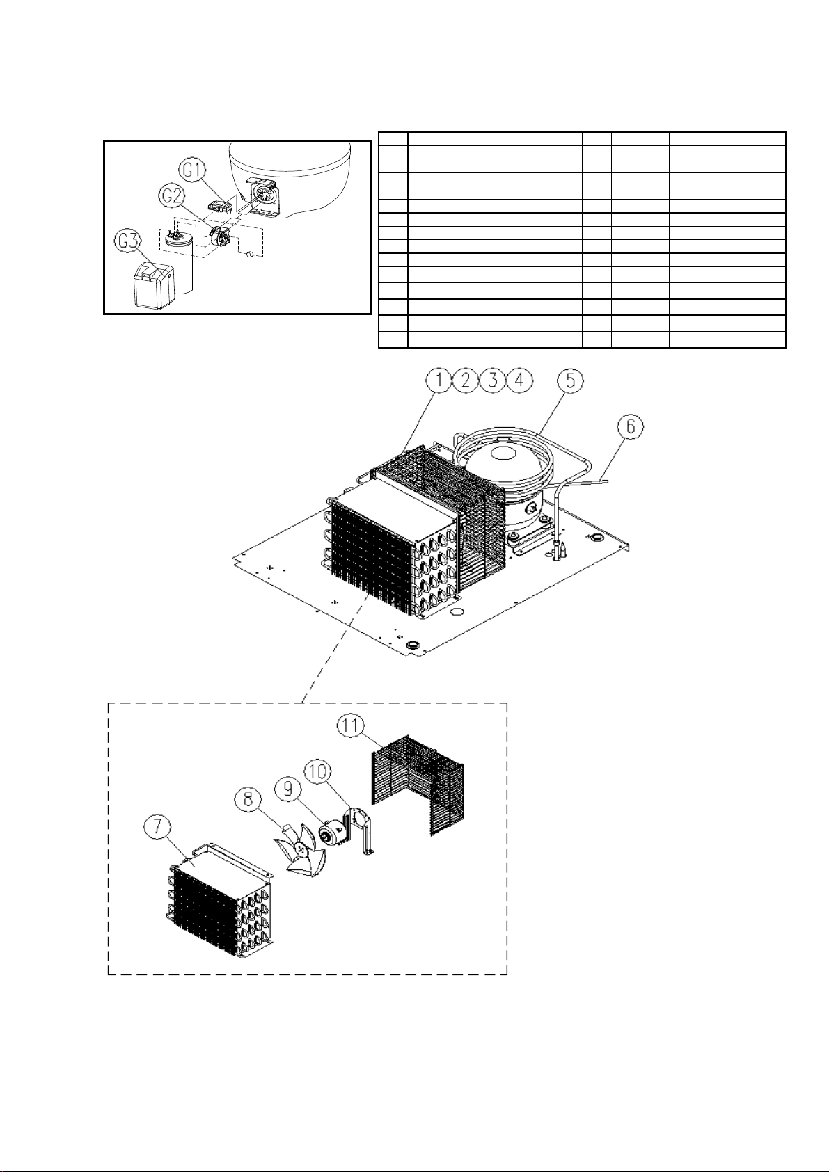
B. Assembly Unit
4
423-311
Cond
115V60H
8204DYCA
8633-010
Cond
AS
2183-610
2104-610
3723-070
Cond
AL
9" CCWR8603-830
Ass'y S
R210 4-981
Pi
134
2113-980
2113-970
1. BSR23T, BSR49T
Model Code Description Material Spec
NO. Qty
R
11
R
21
R
31
51
R
61
R
71
R
81
R7
91
R3313-260 Condenser Fan Motor B/K - -
10 1
R3813-150 Conden ser Fan wi re M SWR10 ∮2.5 275x237
11 1
R7519-100 Overl oad Protector - 4TM 412PFBYY-53
G1 1
R7543-180 PTC Rel ay - J531Q 35E330M 385-3
G2 1
R3813-900 Cover Rel ay
G3 1
Pipe Discharge - Pipe Connect Dryer - Dryer -
pe Dryer - -
uction Pipe - -
Tube Vaccu m - -
enrser
enser Fan Blade
enser Fan Motor -
1
-
--
R-
-
a, 36g
z DAI-
Page 10
Page 11
B. Assembly Unit
2. BSF23T
Model Code Description M aterial Spec
NO. Qty
R2113-970
11
R2113-980 Pi pe Con nect Dryer - -
21
R2183-610 Dryer - R-134a, 36g
31
R2104-981 Pi pe Dr yer - -
41
R8603-830
51
R2104-610 Tu be V accum - -
61
R8633-010 Condenrser AS - -
71
R3723-070 Condenser Fan Blade AL 9" CCW
81
R7423-311 Condenser Fan M otor
91
R3313-260 Condenser Fan M otor B/K -
10 1
R3813-791 Condenser Fan wire
11 1
Pipe Discharge - -
Ass'y Suction Pipe -
-
MSWR10 ∮2.5 275x237
-
115V 60Hz DA I-8204DYCA
-
Page 11
Page 12
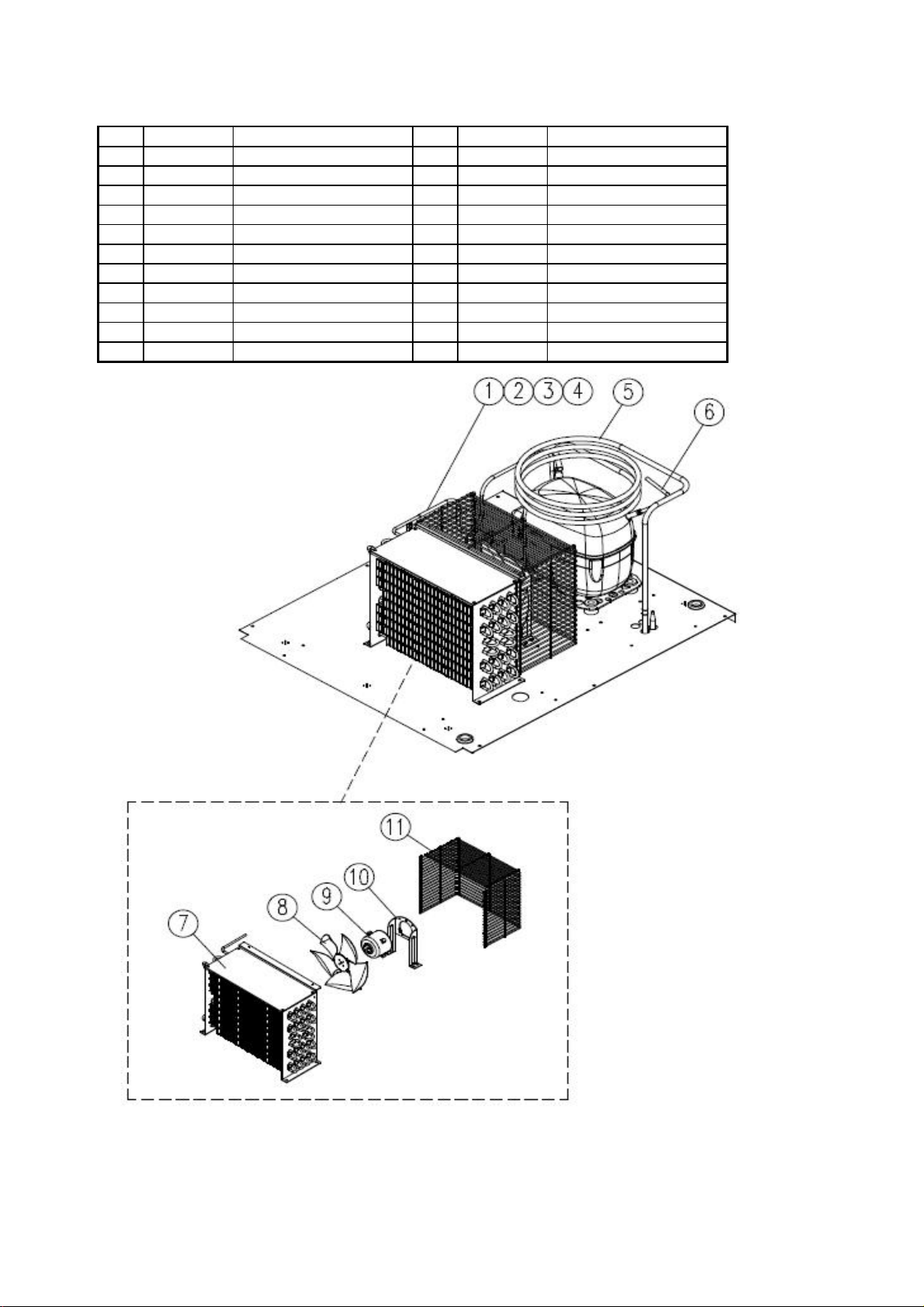
B. Assembly Unit
3. BSF49T
M odel Code
NO. Qty
R2113-570 Di scharge Con nector CU -
11
R8603-813 Ass'y Sucti on Pip e T49F - -
21
R2213-210 Pip e Con nect Dryer T49 - R-134a, 36g
31
R2183-610 Dryer - -
41
R2104-982 Pip e Dryer -
51
R2103-230 Pip e Com p Ch arging -
61
7 R7539-200
R2272-023 Condenr ser A S
81
R3723-070
91
R7423-311 Condenser Fan M otor - 115V60Hz D AI-8204DYCA
10 1
R3313-260 Condenser Fan M otor B/K - -
11 1
R3813-781 Condenser Fan wire M SWR10 ∮2.5
12 1
St ar ti ng D evi ce
Starti ng Capicitor - 410uF
Running Capicitor - 23.5uF
Condenser Fan Blade AL
Material SpecDescription
-
-
-
Code No : 117-7045
1
-9" CCW
Page 12
Page 13
B. Assembly Unit
4. BSR72T
M odel Code Description M aterial
NO. Qty
R2113-960 Pip e D ischar ge T49F - -
11
R845A-010 Ass'y Suction Pi pe T72R - -
21
R2213-200 Pipe Connect Dryer T49
31
R2183-200 Dr yer - -
41
R2104-421 Pip e D ryer - -
51
R2114-321
61
R7539-200
7
R2272-023 Con denrser AS
81
R3723-070 Con denser Fan Blade
91
R7423-311 Con denser Fan M ot or -
10 1
R3313-260 Con denser Fan M ot or B/K - -
11 1
R3813-150 Con denser Fan wir e MSWR10 ∮2.5 275x237
12 1
Compressor Charging Pipe - St ar ti ng D evi ce
Starti ng Capicitor
Running Capicitor - 23.5uF
1
--
- Co de N o : 117-7053
410uF
-
-9" CCW
AL
115V60Hz DAI -8204DYCA
Spe c
Page 13
Page 14
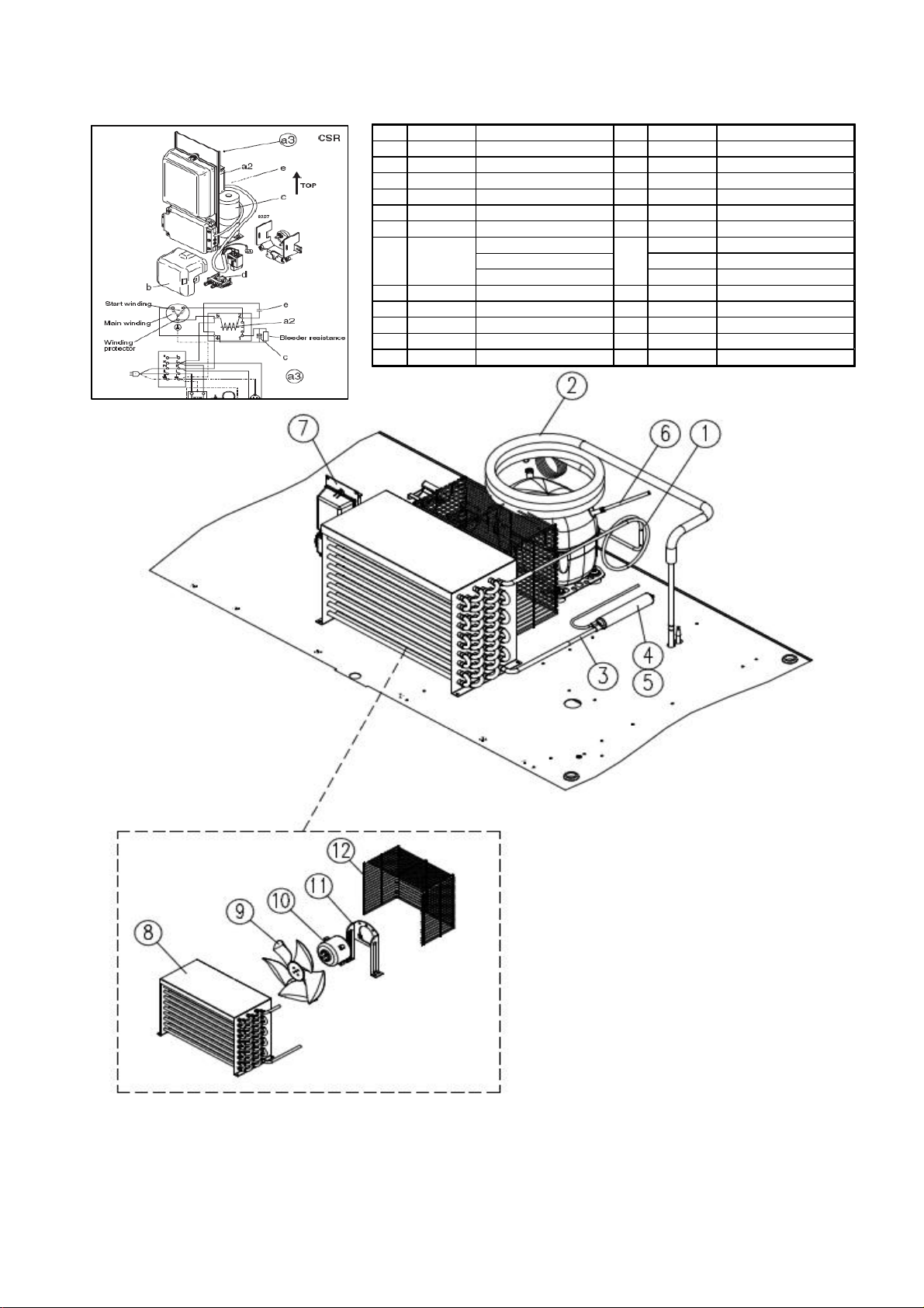
B. Assembly Unit
5. BSF72T
M odel Code
NO. Qty
R2113-311 Con den ser Connector -
11
R2114-330 Compressor Pull Out, B -
21
R845A-020 Ass'y Suction Pi pe T72F -
31
R2104-421 Con denser D ryer Pip e - -
41
R2183-200 Dr yer Ass'y - -
51
R2114-321 Compressor Charging Pipe -
61
R7539-200
7
R2272-030 Con denrser AS -
81
R3723-070 Con denser Fan Blade AL 9" CCW
92
R7423-311
10 2
R3313-260 Con denser Fan M ot or B/K - -
11 2
R3813-770 Con denser Fan wir e-B
12 1
Description M aterial
St ar ti ng D evi ce
Starti ng Capicitor Running Capicitor -
Condenser Fan M otor -
1
MSWR10
-
-
-
-
-
Code No : 117-7073
100uF
20uF
-
115V60Hz DAI -8204DYCA
-
Spe c
Page 14
Page 15
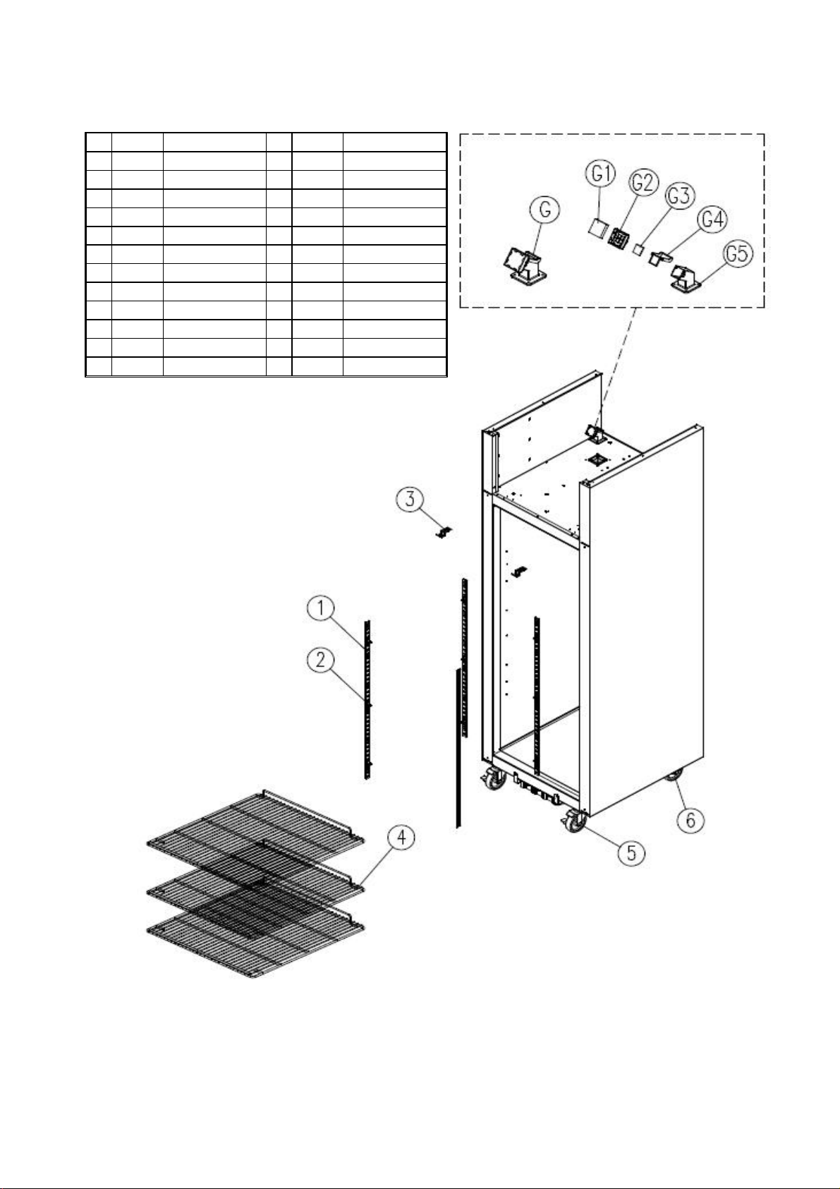
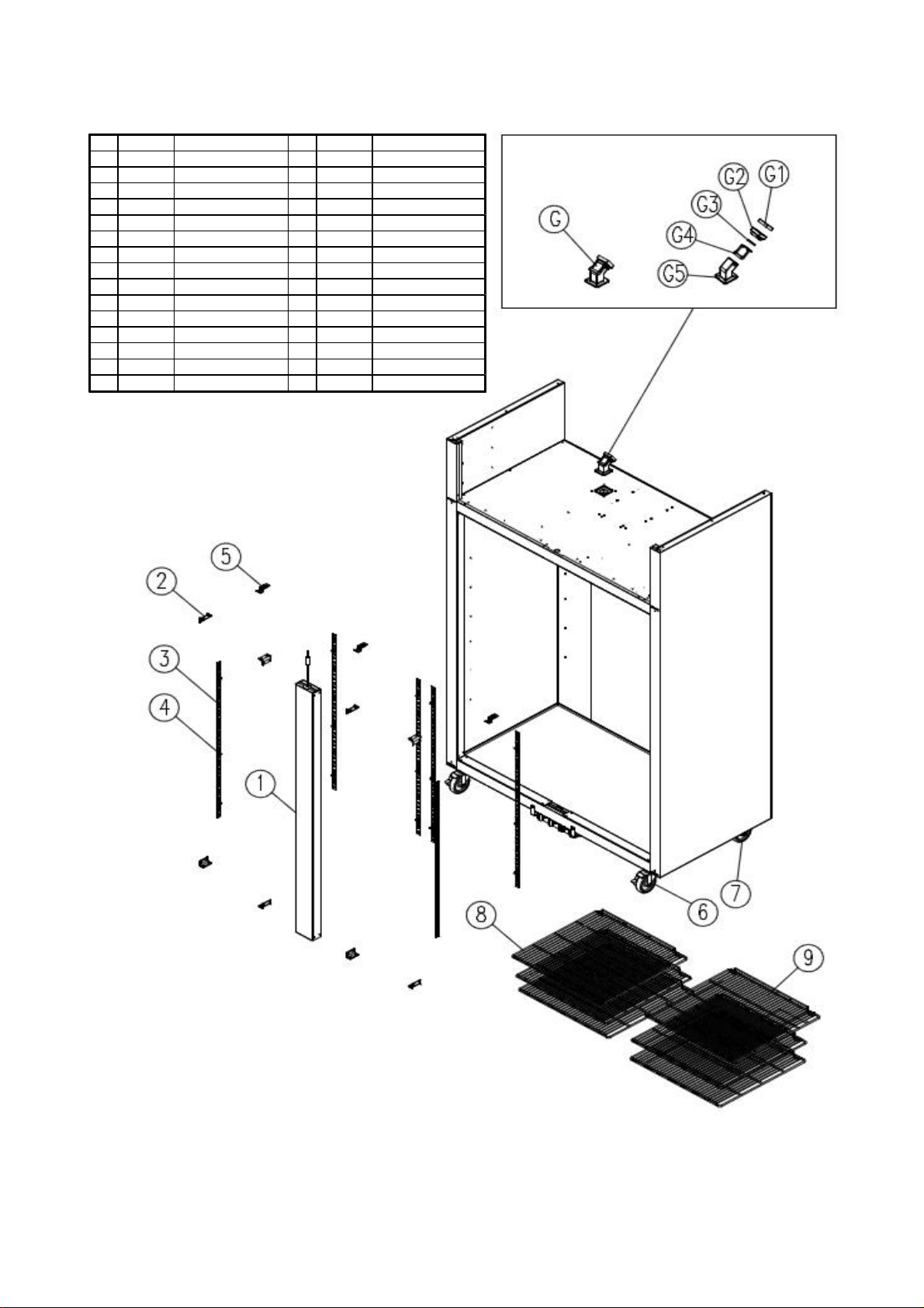
C. Body Assembly
1. BSR23T, BSF23T
Model Code Description Material Spec
NO. Qty
R3373-630 Shelf Standard L - T=1.2, L=930
14
R3313-151 Shelf Clip POM W hite
212
R3114-601
32
R3232-450 Assy Packi ng Shel f 558x587
41SET
R3323-200 Caster - 4" M oving / Stoppi ng
52
R3323-190
62
R8173-130 Check Valve As - -
G1
R3253-050 Filter Check V al ve Filt er Fome #10, T10, Black
G1 1
R3253-040 Cap Ch eck V al ve ABS
G2 1
R3253-060 Packing Fl ap PE T= 4, Wh ite
G3 1
R3253-030 Flap Check V al ve
G4 1
R3253-020 Body Ch eck V alve ABS 60x60x75.05
G5 1
U-Cover Bracket A POM White
Caster 4" M oving
MSWR10
-
45.5x45.5x23.5
ABS 40.5x45x36
Page 15
Page 16
C. Body Assembly
.Qty
424
4
ABSR3253-030
40
36
020
ABS
60x60
lap Check Val
ABS
45.5x45.5x23.5
060
p
Whi
R3253-040
Cap Check Val
R8173-130
R3253-050
Fi l
Fi l
#10, T10, Black
Check Val
3233-162
Shelf-L
MSWR10
R3233-172
Shelf-RH
MSWR10+PE
4" Moving / Stopping
3323-190
C
4" Moving
3323-200
C
WhiteR3314-601
U-C
GI
T=1.2, 61x20
Shelf S
L
930
R3313-151
Shelf Cli p
POM
R325A-030
C
ABS
28.5x28.5x53
R3373-630
cR816A-040
C
p
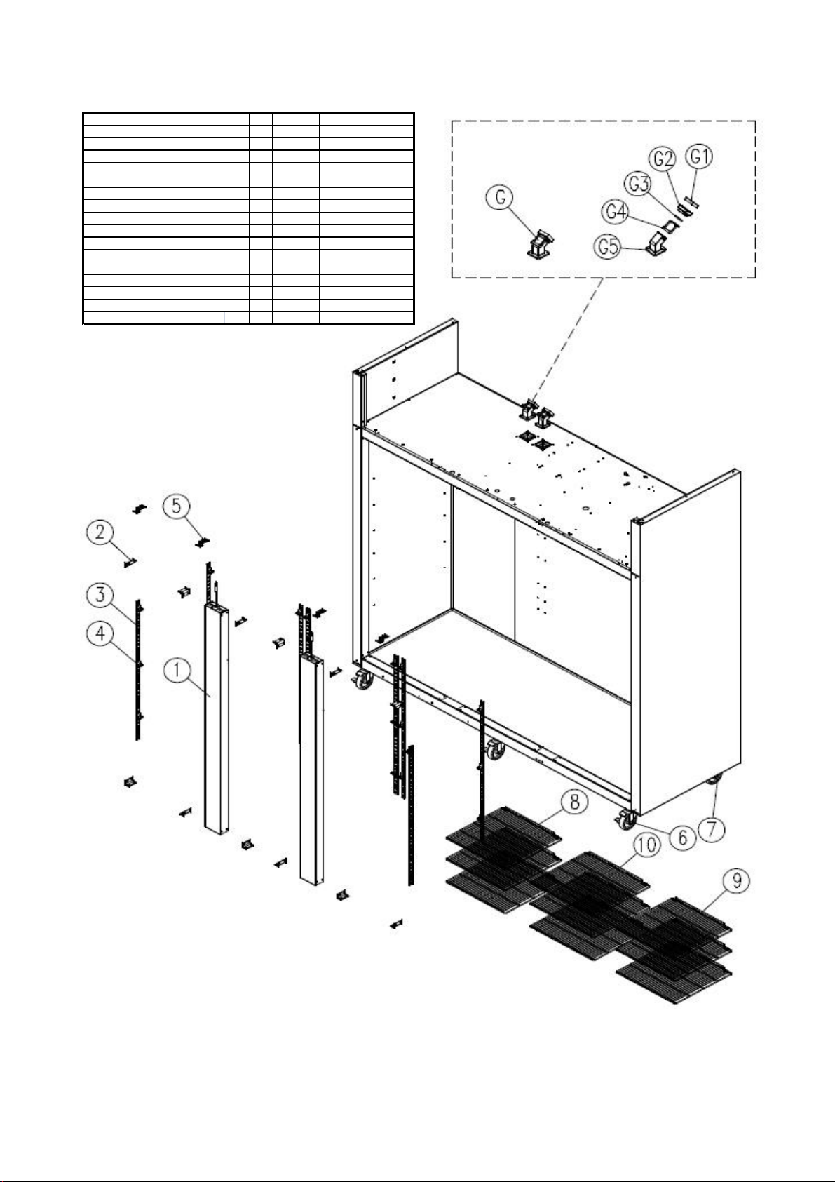
2. BSR49T
Model Code Descri
NO
11
28
36
ross Bar AS T72R-over Corner
tion
tandard
Material Spe
-T=1.2, L=
53
R
62
R
72
R
83
93
G1
G1 1
G2 1
R3253-
G3 1
G
R3253-
G5 1
over Bracket
1
-
-
-
ter Fome
PET=4,
+PE
-
te
.5x45x
x75.05
aster
aster -
F-
ve As
ter Check Valve
ve
Packing Fla
F
Body Check Valve
ve
Page 16
Page 17
C. Body Assembly
y
40
36
ABSR3253-030
020
Cap Check Val
ABS
60x60
lap Check Val
ABS
4
10
k
060
p
Whi
3253-040
-
-R3253-050
-
-
4" Moving
3233-162
Shelf-LF
-
MSWR10
3323-190
C
GIT=1.2, 61x20
3323-200
C
-
4" Moving / Stopping
3314-601
U-C
1.2, L=930
3313-151
Shelf Clip
OM
Whi
3373-630
Shelf S
L
-R325A-030
C
ABS
28
3
816A-030
C
2F
-
-
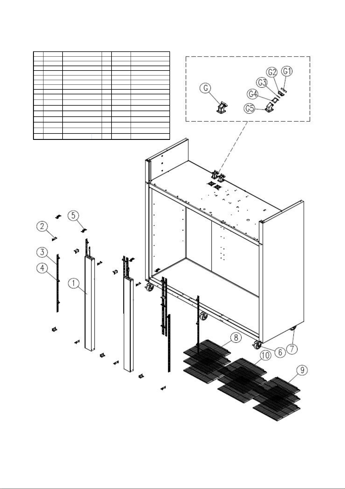
3. BSF49T
NO. Qt
M odel Code Description
R
11
28
R
36
R
424
R
53
R
62
R
72
R
83
R3233-172 Shelf-RH
93
R8173-130
G2
G1 2
R
G2 2
R3253-
G3 2
G4 2
R3253-
G5 2
ro ss Bar AS T7
over Corner
tandard
over Bracket
aster
aster
Check Valve As
Filter Check Valve Filter Fome
ve
Packing Fla
F
Body Check Valve
ve
Material Spec
.5x28.5x5
T=
P
PE T=4,
te
+PE
M SWR10+PE
#
, T10, Blac
5.5x45.5x23.5
te
.5x45x
x75.05
Page 17
Page 18
C. Body Assembly
3253-060
Whi
371A-010
Shelf
2
MSWR10
1.2 61x20
3233-172
Shelf-RH
MSWR10
"
"
3313-151
Shelf Cli
OM
Whi
3114-601
U-C
A
GI
'
R
4. BSR72T
NO. Qty
M odel Code Description M aterial
R816A-040 A ss
12
R325A-030 Cover Corn er ABS 28.5*28.5*53
212
R3373-630 Shelf Standard L -
38
R
436
R
54
R3323-200 Caster - 4
63
R3323-190
73
R3233-162 Shelf-LF - M SW R10+ PE
83
R
93
R
10 3
R8173-130 Check V alve As - -
G2
R3253-050 Fi lt er Ch eck V alve Filter Fome #10, T10, Black
G1 2
R3253-040 Cap Check Val ve ABS 45.5x45.5x23.5
G2 2
R
G3 2
R3253-030 Flap Check V al ve ABS 40.5x45x36
G4 2
R3253-020 ABS 60x60x75.05
G5 Body Check V alve 2
y Cr oss Bar T72
pP
over Bracket
Caster
-T 7
Packing Flap PET=4,
--
T= 1.2, L= 930
te
T=
M oving / Stopping
-4
M oving
-
-
+PE
+PE
te
Sp ec
Page 18
Page 19
C. Body Assembly
y
4
4
MSWR10+PE
R3233-162
Shelf-LF
R3323-200
C
pping
R3323-190
C
R3313-151
Shelf Clip
POM
WhiteR3114-601
U-C
A
GI
T=1.2 61x20
030
C
ABS
28
3
R3373-630
Shelf S
L
930
R816A-030
Ass'y C
T72F
5. BSF72T
NO. Qt
Model Code Description M aterial Spec
12
R325A-
212
38
5
63
73
83
R3233-172 Shelf-RH - M SWR10+ PE
93
R371A-010 Shelf-T72
10 3
R8173-130 Check V alve As - -
G2
R3253-050 Filter Check V alve Filter Fome #10, T10, Black
G1 2
R3253-040 Cap Check Val ve A BS 45.5x45.5x23.5
G2 2
R3253-060 Packing Flap PE T= 4, W hi te
G3 2
R3253-030 Flap Check Val ve ABS 40.5x45x36
G4 2
R3253-020
G5 Body Check Valve 2
ross Bar
over Corner
tandard
over Bracket
aster -4" Moving / Sto
aster -4" Moving
-.5 *28.5 *5
-T=1.2, L=
36
-
- M SWR10+ PE
ABS 60x60x75.05
Page 19
Page 20
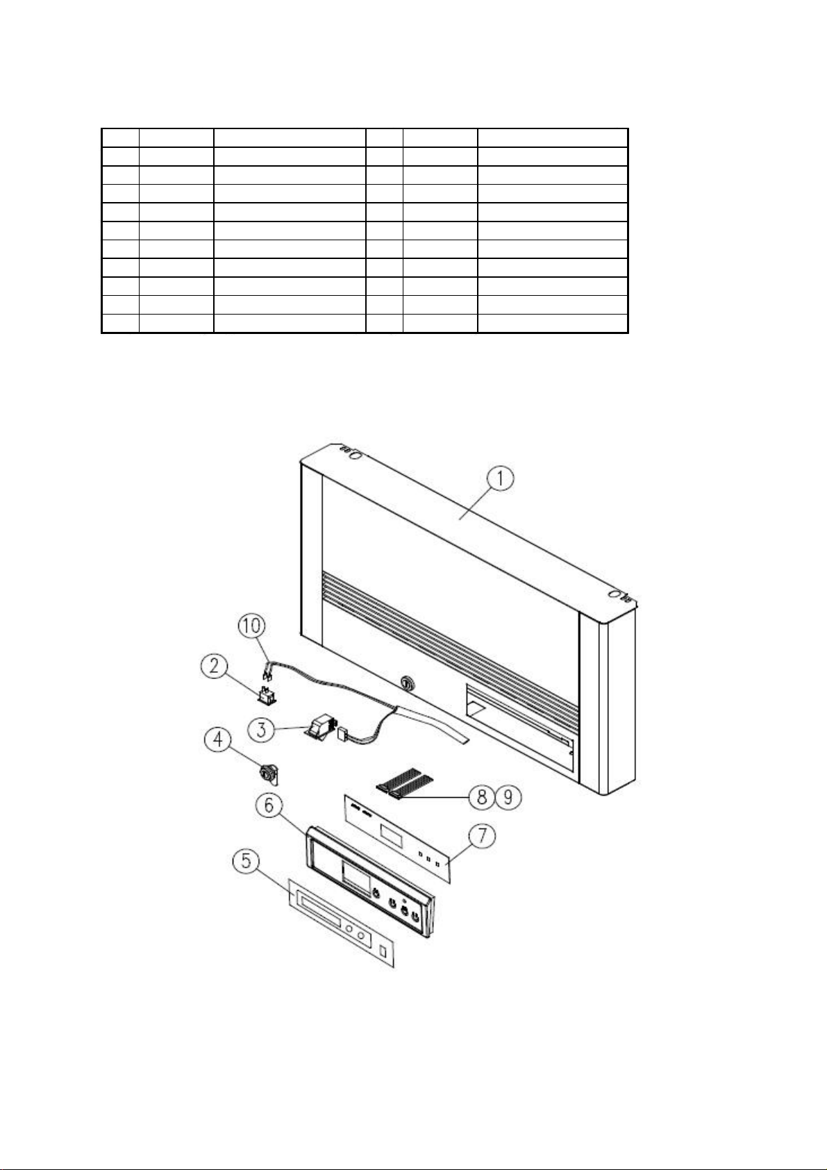
D. Top Grill Assembly
1. BSR23T, BSF23T
Model Code Description
NO. Qty
R8249-630 Top Gril l As T23
11
21
R7203-020 Door Switch - WHT, SP201R-9D
31
R3734-030 Door Lock ing Ass'y
41
51
R4142-122
61
R7129-550 Front PCB-88 DP1
71
81
R7613-320 Harness F-PCB 10P B
91
R7403-080 Ass'y Harness
10 1
Inlay ControlR4103-680
Harness F-PCB 8P BR7613-300
Material Spec
--
- SL112A, 115V 15AR7204-070 Power Switch
--
- T = 0.2, 54 x2 18
ABS Dark Gray, T2x242x72Control Board
- 88 Display
- AGW 24, 8P, 연접 L450
- AGW 24, 10P, 연접 L450
-
Page 20
Page 21
D. Top Grill Assembly
2. BSR49T, BSF49T
M odel Code
NO. Qty
R8249-640
11
R7204-070
21
R7203-020 Door Switch - WH T, SP201R-9D
32
R3734-030 Door Locki ng Ass'y
42
51
R4142-122 Control Board
61
71
R7613-300 Harness F-PCB 8P B
81
R7613-320
91
R7403-080 Harness Swit ch A
10 2
R7373-990 Ass'y Harness Power S/W D
11 1
Top Grill As T49
Power Switch
Harness F-PCB 10P B
Description
Material Spec
-
-
- SL112A, 115V 15A
--
-R4103-680 Inlay Control
T= 0.2, 54x218
ABS
Dark Gray, T2x242x72
88 Display
-R7129-550 Front PCB-88 D P1
AGW 24, 8P, 연접 L450
-
-
AGW 24, 10P, 연접 L450
-
UL AWG18
115V
Page 21
Page 22

D. Top Grill Assembly
3. BSR72T, BSF72T
NO. Qty
R818A-030
11
R7204-070 Power Switch
21
R7203-020
33
R3734-030 Door Locki ng Ass'y
43
R4103-680
51
R4142-122 Cont rol Board ABS D ark Gray, T2x242x72
61
R7129-550 Fron t PCB-88 DP1
71
R7613-300 Harness F-PCB 8P B -
81
R7613-320 Harness F-PCB 10P B
91
R7403-080 Harn ess Switch A - U L AWG18
10 3
R7373-990
11 1
Ass'y Gril l Top T72
Ass'y Harness Po wer S/W D
Description
MaterialM odel Code
-
- SL112A, 115V 15A
- WHT, SP201R-9DDoor Switch
-
-T=0.2, 54x218Inlay Control
-88 Display
- AGW24, 10P, 연접 L450
-
-
AGW 24, 8P, 연접 L450
115V
Spec
Page 22
Page 23

E. Main PCB Box
1. BSR23T, BSR49T
M odel Code Description Spec
NO. Qty
11
R7119-880
21
R7129-700 PCB M ain - FR1, 165x115
31
41
R7613-740 Harness M ain AC-A 23R
51
R7613-890
61
71
R7549-170
81
91
Box M ain PCB
M -PCB Box Cover
Harn ess M ain DC TM -R Ass'y U L
Capacitor StartingR7549-160
Running Capacitor 230vac 50/60Hz-
Material
GIR7119-870
GI
-
-
-
-
Nylon-66R3834-130 Cabl e Cl amp
T= 0.5, 558.34x330.71
T= 0.5, 357.07x218.97
120V60Hz, DT-1213R7504-060 Power Trans
Ass'y UL
200vac 50/60Hz
DA-18N
Page 23
Page 24

E. Main PCB Box
2. BSF23T, BSF49T
M odel Code Description
NO. Qty
R7119-870 Box M ain PCB
11
R7119-880 M -PCB Box Cover
21
R7129-710
31
R7504-060 Power Trans
41
R7253-080 Power Relay
51
R7613-750 Harness M ain AC-A 23F
61
71
PCB M ain
Harness Main DC TM -FR7613-900
Material Spec
T= 0.5, 558.34x330.71GI
GI T= 0.5, 357.07x218.97
- FR1, 165x115
-
120V60Hz, DT-1213
- UZ-2A-BT110, 25A /277V AC
- Ass'y U L
- Ass'y U L
Page 24
Page 25

F. Door Assembly
1. BSR23T, BSF23T
Model Code Description M aterial Spec
NO. Qty
R817A-050 Ass'y Door RH TM -
F1
R4122-281 Han dl e Cover
F1 1
R338A-010 Gasket Door TM
F2 1
R1254-051 Door Rubber Leg
F3 2
R858A-410 Shaft Top Hinge AS SUM 24L
F4 1
R374A -020
F5 1
R828A -020
F6 1
F7 1
R412A-020 Pin Tension SUM 24L -
F8 1
Spring Door RH
Hinge Bottom RH As
-
A BS+ C R도 금 340 .6x 6.8
난연 PVC
Sil i co n ∮16x12
SW -C STS3 04
STS3 04R828A-061 Hinge Top RH As
1508x585
-
T= 4.0
T= 4.0
Page 25
Page 26

F. Door Assembly
2. BSR49T, BSF49T
R412A-020 Pin Tension SUM 24L
F7 2
R828A-050 Assy Hinge Top LF
F8 1
R374A-010 Spring Door LF
F9 1
R375A-010 Stopper Hinge RH
F10 1
R828A-020 Assy Hinge Bottom RH - -
F11 1
R375A-020 Stopper Hinge LF
F12 1
R828A-030 Assy Hinge Bottom LF - -
F13 1
--
SW -C ∮2.3 백색 도금
POM (FW700S)
POM (FW700S)
45.5*31*8
45.5*31*8
Page 26
Page 27

F. Door Assembly
3. BSR72T, BSF72T
Model Code
NO. Qty
R817A-040 Ass'y Door LF TM - -
F
R817A-050 Ass'y Door RH TM - R4122-281 Hand le Cover ABS+CR도금 340.6x6.8
F1 3
R338A-010 Gasket Do or TM 난 연 PV C 1508x585
F2 3
R1254-051
F3 6
R828A-060
F4 2
R858A-410
F5 3
R374A-020
F6 2
R412A-020 Pin Tensi on SU M 24L
F7 3
R828A-050 Assy Hing e Top LF - -
F8 1
R374A-010 Sprin g D oor LF SW-C ∮2.3 백색 도금
F9 1
R375A-010 Stopper Hi ng e RH
F10 2
R828A-020 Assy Hing e Bot tom RH - -
F11 2
R375A-020 Stopper Hi ng e LF
F12 1
R828A-030 Assy Hing e Bot tom LF - -
F13 1
Door Rubber Leg Silicon ∮16x12
Assy Hinge Top RH - Sh aft Top H in ge AS - Spring Door RH SW-C ∮2.3 천연색 도금
1
2
Material SpecDescription
POM(FW700S)
POM(FW700S)
45.5*31*8
45.5*31*8
Page 27
Page 28

G. Evaporator Assembly
1. BSR23T
M odel Code Descript ion
NO. Qty
R2263-072 Evapor ator Assy
11
21
R1143-202 Evap D rai n In sul -S
31
R3853-580 Evap A ir Gui de Left
41
R3853-570
51
R3813-810 Evap Co ver Bracket LF
61
R3813-802
71
R3813-600
81
R3744-090 Evap D rai n Elb ow-U pp
91
R3744-100 Evap D rai n Elb ow-Low
10 1
R2124-021 Evapor ator Dr ain Hose-A
11 1
R7393-020 Lamp Soket
12 1
R7394-010 -
13 1
R3813-990 Lamp Cover - M ips W hi te
14 1
R3203-482 M otor Fix Bracket
15 1
R7423-300 Evapor ator Fan M otor
16 1
R3729-010
17 1
R3812-141 Evapor ator Fan M otor Guard
18 1
19 1
R3314-191 Sensor Bracket
20 1
R7213-112 Temp Di splay Sensor - Wh it e, L=200
21 1
Evap Air Guide Right
Evap Cover Bracket RH
Eva Cover T23
Lam p Bu lb
Evap Fan Blade
Material
-
ALR3743-220 Evap D rai n Pan Smal l
Fo am -P S-T= 17, 256x530
STS443CT-2B T= 0.5, 255.3x155.6
STS443CT-2B T= 0.5, 255.3x155.6
STS430-2B T=1.0, 565x34.8
STS430-2B T=1.0, 565x34.8
AL3003 T= 0.5, 654.6x573
PP White
PP White
Si li con ∮16x12, L= 213
- L-125B 660W 250V
STS430-2B
CCW
CCW 8"
HIPS V H-1800EX
-R7403-110 Harness Lamp L
PP White
Spe c
-
25T10/120V 25W
T= 1.0, 90x146
AC115V 60Hz DAI-8204DYCA-1
UL AWG 18
Page 28
Page 29

G. Evaporator Assembly
d
2. BSF23T
M odel Code Description M aterial Spec
NO. Qty
R2263-051 Evapor ator Assy
11
R7313-331 Def rost Heat er - 115V /445W
21
R3743-220 Evap D rain Pan Smal l AL -
31
R1143-202 Evap D rain Insul -S Foam-PS T= 17, 256x530
41
51
R3853-570 Evap A ir Gui de Ri ght STS443CT-2B T= 0.5, 255.3x155.6
61
R3813-810 Evap Cov er Bracke t LF STS430-2B T= 1.0, 565x34.8
71
R3813-802 Evap Cov er Bracke t RH STS430-2B T=1.0, 565x34.8
81
R3813-604 Eva Cover T23 AL3003
91
R3744-090 Evap D rain Elbow-U pp PP Whit e
10 1
R3744-100 Evap D rain Elbow-Lo w
11 1
R2124-021 Evapor ator Dr ain Hose-A Sil icon ∮16x12, L=213
12 1
R8393-030 Heat er Cord Drai n H ose - 115V 10W
13 1
R7393-020 Lamp Soket -
14 1
R7394-010 Lamp Bulb -
15 1
R3813-990 Lamp Cover - M ips W hite
16 1
R3203-482 M otor Fix Bracket STS430-2B T=1.0, 90x146
17 1
R7423-300 Evaporator Fan M otor
18 1
R3729-010 Evap Fan Blade CCW 8"
19 1
R3812-141 Evapor ator Fan M otor Guar
20 1
R7403-110
21 1
R3314-191
22 1
R7213-082
23 1
R7303-174 Heat er Drai n P an - 115V ,90W
24 1
Evap A ir Guide LeftR3853-580
Harness Lamp L UL AWG 18
Sensor Bracket
Temp Ther misor, FRE
-
-
STS443CT-2B T= 0.5, 255.3x155.6
T= 0.5, 654.6x573
PP
White
L-125B 660W 250V
25T10/120V 25W
CCW
AC115V 60Hz DAI-8204D YCA-1
HIPS V H-1800EX
White
PP
Yellow
-
Page 29
Page 30

G. Evaporator Assembly
3. BSR49T
M odel Code Description Materi al Spec
NO. Qty
R3853-800 Evap Cover Support LF STS443CT-2B T= 0.5, 519.4x176.7
11
R3813-554 Eva Cover T49R
21
R3853-790 Evap Cover Support RH STS443CT-2B T= 0.5, 519.4x176.7
31
R3812-141
41
R2263-082 Evaporato r A ssy - -
51
R3743-041 Evaporato r D rain Fan-M id AL -
61
R3853-050 Evap Ai r Gu ide Left
71
R1143-222 Evaporato r D rain In sul -M Foam-PS
81
R3853-040 Evap Ai r Gu ide Righ t
91
R3203-482 M otor Fix Bracket STS430-2B T= 1.0, 90x146
10 1
R7423-300 Evaporato r Fan M otor CCW
11 1
R3729-010 Evap Fan Blade CCW 8"
12 1
R3744-090 Evap Drai n Elbow-Upp PP Wh ite
13 1
R3744-100 Evap Drai n Elbow-Low PP Wh it e
14 1
R2124-021 Evaporato r D rain Hose-A Sil icon ∮16x12, L= 213
15 1
R7393-020 Lamp Soket - L-125B 660W 250V
16 1
R7394-010 Lamp Bul b - 25T10/120V 25W
17 1
R3813-990 Lamp Cover - M ips Wh ite
18 1
R7403-110 H arness Lamp L - UL AW G 18
19 1
R3314-191 Sensor Bracket PP Wh ite
20 1
R7213-082 Tem p Displ ay Sensor - Wh ite, L=200
21 1
Evaporator Fan Motor Guard
STS443CT-2B T= 0.5, 727x522
HIPS VH -1800EX
AL T= 0.5, 255.3x155.6
T= 17, 256x622
AL T= 0.5, 255.3x155.6
AC115V 60Hz DAI-8204DYCA-1
Page 30
Page 31

G. Evaporator Assembly
4. BSF49T
M odel Code Descri ption M aterial Spec
NO. Qty
R3853-800 Evap Cover Support LF STS443CT-2B T= 0.5 , 519.4x176.7
11
R3813-564 Eva Cover T49F STS443CT-2B T=0.5, 727x522
21
R3853-790 Evap Cover Support RH STS443CT-2B T= 0.5 , 519.4x176.7
31
R3812-141
42
R2263-062 Evapora tor Assy - -
51
R7313-440 Def rost Heat er 60 -
61
R3743-041 Evapora tor Dra in Fan-Large AL -
71
R7313-431 Heat er D rai n Pan _ 115V 90W
81
R3853-050 Evap A ir Gui de Left AL T=0.5, 255.3x155.6
91
R1143-212 Evapora tor Dra in Insu l-L Foam-PS T=17, 256x800
10 1
R3853-060 Evap A ir Gui de M id A L T= 0.5 , 245x127
11 1
R3853-040 Evap A ir Gui de Rig ht A L T= 0.5, 255.3x155.6
12 1
R3203-482 M otor Fix Br acket STS430-2B T=1.0, 90x146
13 2
R7423-300 Evaporator Fan Mot or CCW
14 2
R3729-010 Evap Fan Bl ade CCW 8"
15 2
R3744-090 Evap D rain Elbo w-U pp PP Whi te
16 1
R3744-100 Evap D rain Elbo w-Low PP W hit e
17 1
R2124-021 Evapora tor Dra in Hose-A Silicon ∮16x1 2, L=213
18 1
R7313-490 Heat er Co rd D rai n H ose - 115V1 0W
19 1
R7393-020 Lamp Soket - L-125B 660W 250V
20 1
R7394-010 Lamp Bulb - 25T10/120V 25W
21 1
R3813-990 Lamp Cover - M ips Wh ite
22 1
R7403-110 Har ness Lamp L - U L AW G 18
23 1
R3314-191 Sensor Bracket PP Wh ite
24 1
R7213-082 Temp Disp lay Sensor - Wh ite , L=200
25 1
Evapor ator Fan Motor Guard
HIPS V H-1800EX
AC115V 60Hz DAI-8204D YCA-1
Page 31
Page 32

G. Evaporator Assembly
5. BSR72T
M odel Code Descri ption M aterial Spec
NO. Qty
R3853-800 Evap Cover Support LF STS443CT-2B T=0.5, 519.4x176.7
11
R325A-010 Co ver Eva T72R STS443CT-2B T= 0.5, 845x653.5
21
R3853-790 Evap Cover Support RH STS443CT-2B T= 0.5, 519.4x176.7
31
R3812-141
42
R840A-010 A ss'y Evaporat or T72R AL -
51
R3743-031 Evap orat or Drai n Fan-Larg e
61
R3853-050 Evap Ai r Gu id e Left A L T= 0.5, 255.3x155.6
71
R1143-212 Evap orat or Drai n Insu l-L Fo am-PS T=17, 256x800
81
R3853-060 Evap Ai r Gu id e M id A L T= 0.5, 245x127
91
R3853-040 Evap Ai r Gu id e Rig ht AL T= 0.5, 255.3x155.6
10 1
R3203-482 M otor Fix Bracket STS430-2B T= 1.0, 90x146
11 1
R7423-300 Evap orat or Fan M otor CCW
12 1
R3729-010 Evap Fan Blad e CCW 8"
13 1
R3744-090 Evap Drain Elbow -Up p PP White
14 1
R3744-100 Evap Drain Elbo w-Low
15 1
R2124-021 Evap orat or Drai n Hose-A
16 1
17 2
R7393-021 Lam p Sok et - L-125B 660W 20V
18 2
R3813-991 Lam p Cover
19 2
R7403-111 H arn ess Lamp L - U L AWG 18
20 2
R3314-191 Sen sor Bracket PP W hite
21 1
R7213-082 Temp D ispl ay Sensor - Wh it e, L=200
22 1
Evaporator Fan Motor Guard
Lam p Bu l bR7394-010 - 25T10/120V 25W
HIPS V H-1800EX
AL(Coating) -
AC115V 60Hz DAI-8204DYCA-1
PP W hi te
Si l icon ∮16x12, L= 213
- M ips White
Page 32
Page 33

G. Evaporator Assembly
5. BSF72T
Model Code D escripti on M at erial Spec
NO. Qty
R3853-800 Evap Cover Su pport LF STS443CT-2B T= 0.5, 519.4x176.7
11
R325A-0 20 Cover Eva T72F STS443CT-2B T= 0.5, 1082x654
21
R3853-790 Evap Cover Su pport RH STS443CT-2B T= 0.5, 519.4x176.7
31
R3812-141
42
R2263-100 Ass'y Evaporat or T72F CU + AL -
51
R7313-440 Defrost Heater 60 - 115V 900W 14.7Ω
61
R3743-240 Evaporato r Dr ain Fan-Lar ge AL(Coat ing) -
71
R7313-431 Heater Drai n Pan _ 115V 90W
81
R3853-050 Evap Ai r Gui de Left AL T= 0.5, 255.3x155.6
91
R1143-212 Evaporato r Dr ain Insu l-L Foam-PS T= 17, 256x8 00
10 1
R3853-060 Evap Ai r Gui de M id A L T= 0.5, 245x127
11 1
R3853-040 Evap Ai r Gui de Right AL T= 0.5, 255.3x155.6
12 1
R3203-482 Mo tor Fix Bracket STS430-2B T= 1.0, 90x146
13 2
R7423-300 Evaporato r Fan M otor CCW
14 2
R3729-010 Evap Fan Blade CCW 8"
15 2
R3744-090 Evap Drai n Elb ow-U pp PP W hit e
16 1
R3744-100 Evap Drai n Elb ow-Low PP Wh ite
17 1
R2124-021 Evaporato r Dr ain Hose-A Sili con ∮16x12, L= 213
18 1
R7313-490 Heater Cord Drai n H ose - 115V 10W
19 1
R7394-010 Lamp Bul b - 25T10/120V 25W
20 2
R7393-021 Lamp Soket - L-125B 660W 20V
21 2
R3813-991 Lamp Cover - Mi ps Whi te
22 2
R7403-111 Harness Lam p L - UL AW G 18
23 2
R3314-191 Sensor Bracket PP Wh ite
24 1
R7213-082 Temp D ispl ay Sensor - Yel low
25 1
Evaporator Fan Motor Guard
HIPS V H-1800EX
AC115V 60Hz DAI-8204DYCA-1
Page 33
Page 34

H. Vapori Assembly
1. BSR23T, BSF23T, BSF49T
M odel Code Description M aterial Spec
NO. Qty
R3132-600 Case Vapori T49 ABS 602.5x275x106.5
11
R3422-050 Cover DC M otor T49 ABS 280.5x131x11.5
21
R3422-030 Case DC M otor T49 ABS 283x143.5x69.5
31
R7423-442 M otor DC V apori - DC12V, 250mA, 3000RPM
41
R1154-090 Wicking Drain Water 부직포 2.5Tx480x63.5
58
R3853-780 Gui de Wi cking (49D) PP T=1.5, 269x40
62
R3313-730 Bracket Case V apori Front STS304 T= 1.2, 85.5x20.5
72
Page 34
Page 35

H. Vapori Assembly
2. BSR49T
M odel Code Description M aterial Spec
NO. Qty
R3132-600 Case Vapori T49 ABS 602.5x275x106.5
11
R3422-050 Cover DC M otor T49
21
R3422-030
31
R7423-442
41
R3743-400 Holder V apori Heater
55
R7703-290
61
R3313-730 Brack et Case V apori Front STS304 T= 1.2, 85.5x20.5
72
Case DC M otor T49 ABS 283x143.5x69.5
Motor DC Vapori -
Heater Vaporizer 115V 50W Sheath Heater
ABS 280.5x131x11.5
DC12V , 250mA, 3000RPM
Sil icon 33x20x13.5
Page 35
Page 36

H. Vapori Assembly
3. BSR72T
M odel Code Description M aterial Spec
NO. Qty
R3132-600 Case Vapori T49 ABS 602.5x275x106.5
12
R3422-050 Cover DC M otor T49 ABS 280.5x131x11.5
22
R3422-030 Case DC M otor T49 ABS 283x143.5x69.5
32
R7423-442 M otor DC V apori - DC12V, 250mA , 3000RPM
42
R3743-400 Hol der V apori Heater Sili con 33x20x13.5
510
R7703-290 Heater Vaporizer 115V 50W Sheath Heat er
62
R3313-730 Brack et Case V apo ri Fron t STS304 T= 1.2, 85.5x20.5
74
R223A-020
82
R223A-010 FITTING DIVIDER VAPO RI - BSPP AM CB 1207M
92
R225A-010 FITTING TUBE - PE TUBE ¢12 L= 100mm
10 1
FITTING DIVIDER VAPORI NUT
- PP NU T 20M
Page 36
Page 37

H. Vapori Assembly
3. BSF72T
M odel Code Description Material Spec
NO. Qty
R3132-600 Case V apori T49 ABS 602.5x275x106.5
12
R3422-050 Cover DC M otor T49 ABS 280.5x131x11.5
22
R3422-030 Case DC M o tor T49 ABS 283x143.5x69.5
32
R7423-442 M ot or DC V apori - DC12V, 250mA , 3000RPM
42
R1154-090
516
R3853-780 Guide Wicki ng (49D) PP T= 1.5, 269x40
64
R3313-730 Bracket Case V apori Front STS304 T= 1.2, 85.5x20.5
74
R223A-020
82
R223A-010 FITTING DIV IDER V APORI - BSPP AM CB 1207M
92
R225A-010 FITTING TUBE - PE TU BE ¢12 L=100mm
10 1
Wicking Drain Water
FITTING DIVIDER VAPORI NUT
부직포
- PP NUT 20M
2.5Tx480x63.5
Page 37
Page 38

Ⅲ. WIRING DIAGRAM
A. BSR23T(LRT-23S)
B. BSF23T(LFT-23S)
Page 38
Page 39

Ⅲ. WIRING DIAGRAM
C. BSR49T(LRT-49D)
D. BSF49T(LFT-49D)
Page 39
Page 40

Ⅲ. WIRING DIAGRAM
E. BSR72T(LRT-72T)
F. BSF72T(LFT-72T)
Page 40
Page 41

Ⅳ. General Information
A. Control Buttons and Functions
1. Display Board
a) Setting
- Down : level-down of temperature.
- Up: level-up of temperature
Preset Setting Level Level Note
Refrigerator
℃
Freezer -18 -23~-15 9 Step
Refrigerator
℉
Freezer 0 -9~5 15 Step
b) Display
① 888 SEGMENT Display
- The temperature setting button pressed, the 888 Segment blinks
at 0.5-second intervals showing the set temperature.
- Temperature setting is available with the △▽ buttons.
- The setting is auto-saved in 5 seconds and the current inside temperature is displayed.
② Temperature Display
- Regular mode: The inside temperature is displayed.
- Pre-cool mode: The off-point temperature set is displayed.
ex) -0.4℉(-18℃) set, the temperature of “-4℉(-20℃),” identical to the compressor-off
temperature, is shown for -4℉(-20℃) or below.
2 -2~4 6 Step
35 28~39
12 Step
℃
℉
- In defrosting: “dF” display: Defrosting heater on -> 5-min respite -> fan (respite)
Display until 1 minute after the inside fan is on (regular mode)
*In refrigerator, the actual inside temperature is shown.
③ Door LED Display
- LED blinking while the door is opened.
Page 41
Page 42

c) Location
The display board is located on the right hand side of "Top Grill Assembly"
From the display board, various electronic controls and function can be adjusted.
See " C - 3."
Top Grill
assembly
Door
d) Lay out
Ribbon Cable Connector
Door Open LED
RT Sensor
888 SEGMENT
* RT Sensor : Ambient temperature Sensor
DOWN Button
UP Button
Page 42
Page 43

2. Control Board
1. Fragile, handle very carefully.
2. The control board contains integrated circuits, which are susceptible to failure
due to static discharge. It is especially important to touch the metal part of the
unit before handling or replacing the board.
3. Do not fix the electronic devices or parts on the board in the field. Always
replace the whole board assembly if it goes bad.
4. To prevent damage to the borad, do not touch the electronic devices on the
board or the back of the board.
5. Do not short out power supply to test for voltage.
a) Location
The control box is located behind the "Top Grill Assembly".
If you remove 7 fixing screws, the control box can be found.
CAUTION
Top Grill
assembly
Screw
Control
box
Page 43
Page 44

b) Control Board Layout
r
r
r
r
y
y
r
y
r
r
CON7
Cabinet
Heater
CON14 Transformer DC
CON5 Defrost SENSOR
RY3
C-Heate
Rela
E-Fan
Rela
RY4
CON9 Room Sensor
RY2
D-Heate
Rela
CON2
Power Cord
CON10 Display cable 10P
RY1
Compresso
Relay
Door Signal
CON6
Compresso
Test Switch
CON11 Display cable 8P
CON12
CON13
Vaporizer Fan
CON4
Evaporato
Fan
CON1
Transforme
AC
CON4
Defrost Heate
* Regerator models (BSR23T, BSF23T) do not have CON4 and RY2.
Page 44
Page 45

B. Sequence of Operation and Timing Charts
A
k
1. Refrigerator ( BSR23T, BSR49T)
a) Sequence of Operation
POWER ON
BOARD CHECK
(Type & Beep will blink
-->℉/℃ will blink
--> Model Name will blink
--> All LED will blink)
1. Frame Heater on*
Cycle On(Cut-on
temperature reached)
1. Compressor on
2. Condenser fan on
5 minutes delay
1. Compressor start-up
2. Condenser fan start-up
3. Evaporator fan start-up
Defrost Start
Preprogrammed time interval*
1. Comperssor off
2. Condenser fan off
* default : 5hr
Cycle Off(Cut-out
temperature reached)
1. Compressor off
2. Condenser fan off
Defrost End
fter 30 minutes, Chec
set return temperature*
1. Comperssor on
2. Condenser fan on
Normal cycling continues
Note : The start circuit of the compressor is timed such that at power-up and during
any compressor off time, there will be at least 5minutes delay before the com pressor will start. The only exception is when the overload activates and deact ivates. The compressor has a 5 minute minimum run time during every run cycle.
Page 45
Page 46

b) Timing Chart (BSF23T, BSF49T)
P
ON
5min
Max.
45min
* Defa ult s etting 8hour s , a djustab le
▲ S etva lue minus 8℃
● Defros t senser Temp' - 10℃
Max.
5min
Max . 5 0min
*8 hours
Defrost S tart
Ti me
5 min.
ON
No meani ng
Pr e-se t val ue
Pre-set val ue
Defrost Sensor
Pr e-se t val ue
Roo m Sensor
Com pressor
ON
OFF
Co nd enser Fan
ON
OFF
Evap orator Fan
ON
OFF
Defrost Heater
ON
OFF
Defrost indicator
ON
OFF
*Cabinet Heater
ON
OFF
OFF
Vaporizer Fan
ower
Page 46
Page 47

2. Freezer (BSF23T, BSF49T)
a) Sequence of Operation
POWER ON
BOARD CHECK
(Type & Beep will blink
--> ℉/℃ will blink
--> Model Name will blink
--> All LED will blink)
1. Frame Heater on*
Cycle On(Cut-on
temperature reached)
1. Compressor on
2. Condenser fan on
Defrost End
Defrost sensor reaches 51℉
(11℃)
Defrost Heater off
5 minute delay
1. Compressor start-up
2. Condenser fan start-up
3. Evaporator fan start-up
Pre-Cool
Cabinet Temp' falls to
set temp' 17℉(-8℃) within
45minutes.
Five minutes after defrost
heater off
1. Compressor on
2. Condenser fan on
Cycle Off(Cut-out
temperature reached)
1. Compressor off
2. Condenser fan off
Defrost Start
Preprogrammed time interval*
1. Comperssor off
2. Condenser fan off
3. Evaporator fan off
4. Defrost Heater on
5."dF" displayed
*Default : 8hours
Defrost sensor reaches below 14℉(
-10℃)
1. Evaporator fan on
2. Cabinet Temp displayed
Normal cycling continues
Note : The start circuit of the compressor is timed such that at power-up and during
any compressor off time, there will be at least 5minute delay before the com pressor will start. The only exception is when the overload activates and deact ivates. The compressor has a 5 minute minimum run time during every run cycle.
Page 47
Page 48

b) Timing Chart
P
ON
* Defa ult s ettin g 8hours, a djustab le
▲ Set va lue minus 8℃
● Defros t senser T emp' -10℃
Max.
5min
5min
Max. 50min
Max.
45min
*8 hours
Defrost S tart
Time
5 min.
ON
No meani ng
Pre-set val ue
Pr e-set value
Defrost Sensor
Pre-set value
Room Sensor
Co m p ressor
ON
OFF
Co nd ense r Fan
ON
OFF
Evaporator Fan
ON
OFF
Defrost Heater
ON
OFF
Defrost indicator
ON
OFF
*Cabinet Heater
ON
OFF
OFF
Vaporizer Fan
ower
Page 48
Page 49

C. Board Details & Setting
1. Board Details
MODE Description
No.
Initial power
1 1. Stand by
supply
- In operation, all output is off for 2 seconds.
- In 2 seconds, the buzzer sounds with 2 blinks at a 0.5-second interval.
- Then, additional 2 blinks of “℉/℃” follow at a 0.5-second interval.
- Model name blinks 5times.
- Every LED blinks 3 times at 0.5-second intervals.
- The cabinet temperature is displayed.
2. Initial Defrost Check
< Type F > : BSF23T, BSF49T
- The temperature of defrost sensor controls operation
1) The compressor is on at 38℉(3.5℃) or above.
2) The defrost mode is on when every sensor is at 38℉(3.5℃)
or below
※ The pre-cool mode is on 5 minutes after the defrosting mode is on.
Board Details
<Type R > : BSR23T, BSR49T
- The temperature of room sensor controls operation.
1) The compressor is on at 41℉(5.0℃) or above
2) The defrost mode is on below 41℉(5.0℃).
Regular
2 - 5-min compressor delay
Operation
3 Freezer - Defrost is available at 5, 6, 7, 8, 9 or 10-hour intervals.
(The compressor stops operation for 5 minutes after it is off.)
- The compressor is turned on or off
depending on the room sensor temperature.
The default setting is 8 hours.
Page 49
Page 50

Board Details
MODE Description
No.
4 Refrigerator - defrosting every 5 hours
5 Defrost system - This process is to lower the inside temperature
- Freezer before the defrost heater is on.
1. PRE-COOL - When defrost begins, the pre-cool mode is on
before the defrosting heater is on.
- The defrost heater is on if the cabinet temperature
goes down to or below 17℉(-8℃) within 45 minutes.
- The maximum duration of the pre-cool mode is 45 minutes.
2. HEATER ON - When the D-sensor on evaporator reaches 51℉(11℃),
the defrost heater is off.
- The defrost heater can remain on for up to 50 minutes.
- In case of a D-sensor error,
the heater is in operation for 20 minutes.
Then, it is off if the room sensor temperature is 28℉(-2℃) or above.
- In case of a defrosting or room sensor error,
the heater is operates for up to 20 minutes.
- When the D-sensor does not resume
the defrosting temperature even 50 minutes
after the defrosting heater is on, the error code is automatically saved.
※ The pre-cool mode is off in case of a defrosting limit error.
3. Respite - When the defrost heater turns off,
a 5-minute respite is given to stabilize the freezing cycle.
-Defrost heater, fan and compressor is all off.
4. FAN stop - When the respite is over, the fan stops operation for up to 5 minutes
to prevent the heated evaporator air from entering inside.
- Only the compressor is in operation in this mode,
cooling the evaporator and cabinet air.
- If the D-sensor temperature goes down to or
below 14℉(-10℃) within 5 minutes,
the fan-stop mode is over and regular operation is available.
6 Defrost system - Defrost is available with the operation of the cooling fan.
- Refrigerator - In case of a refrigerator room sensor error,
a 30-minute defrosting begins.
- In 30 minutes, the system checks the refrigerator room sensor temp'.
- Auto-return is on at a certain temperature.
※ If the set temperature is 30℉(-1℃) or below, the return temperature is
37℉(+3℃). If the former is 32℉(0℃), the latter is 41℉(5℃).
Page 50
Page 51

Board Details
MODE Description
No.
7 Cabinet heater - If the compressor-on temperature is lower than the ambient
control temperature, the heater is off.
- If the ambient temperature is 78℉(26℃) or above, the heater is on.
- If the ambient temp' is between 78℉(26℃) and the compressor-on
temp', the heater is turned on and off every 10 minutes.
- If the RT temperature is lower than the compressor-on temperature,
the code heater is off.
8 Refrigerator - When the compressor is off, the evaporator fan is off.
Prevention of - To prevent the refrigerator evaporator from over-frosting,
over-frosting the fan starts operation irrespective of the compressor-on
system or –off temperature if the inside temperature is 32℉(0℃) or below.
9 Door - Door opening: the door-open lamp blinks
- 5 minutes after door opening, the buzzer sounds
and the lamp blinks until it is closed.
10 Evaporator - The fan starts operation when the compressor is on.
fan control - The fan stops operation when the door is opened.
- The fan is off when the compressor is off.
(The fan starts operation irrespective of the compressor-on
or –off temperature if the inside temperature is 32℉(0℃) or below.)
- The fan start operation 3 seconds after the door is closed.
2. Compressor Operation and Re-run Prohibition
a) Compressor Operation
1) The compressor is not to be operated for 5 minutes after it is off.
2) Operation is to depend on the refrigerator and freezer sensor temperatures.
3) Operation is to depend on the preset difference. ( Ex) preset difference >±35℉(2℃): )
- The compressor is on at 35℉(2℃) or more above the set temperature and
off 35℉(2℃) or more below the set temperature.
b) AC Load Sequential Control
1) Simultaneous operation is not available.
An operation starts 1.5 seconds later than another.
COMP 1.5sec
FAN 1.5sec 1.5sec
HTR
Page 51
Page 52

3. SETTING
The Up and Down keys pressed at the same time, the setting mode is on.
S E L SEL is displayed on the 888 Segment
NO
1
2
3
4
5
6
7
8
MODE SW 4(△) DISPLAY Note
Forced Defrost once ds
Mode setting twice OF
TEST 3 times St
Errer check 4 times no
Function change 5 times 23F
℉ / ℃ change 6 times F
Cabinet Heater
setting change
LED check and
EEPROM clear
7 times Ht
8 times All LEDs blinking
a) Forced Defrost mode
1) Display : : “ds” is displayed on the 888 Segment.
2) Activation: The Down switch (▽) pressed in 1),
the setting mode is off and forced defrosting mode is on.
② 888 SEGMENT displays "dF".
b) Mode setting
1) Display: The 888 Segment is displayed like the following.
0 F In 1 second 0 0
Display in 2seconds
(LEDs are off except 888
segment.)
2) Control: The Up button (△) pressed,
the setting mode is altered in order of off-point change, DIF change,
temperature revision and defrosting duration adjustment.
00 a second after 0F: level-up and –down by 32℉(0.5℃)
between 23℉(-5.0℃) and 41℉(+5.0℃)
① 0F, display 00 after a second : level-up and –down by 32℉(0.5℃) between.
(Decimal point and the zero in front of it omitted: 32℉(5) displayed for 32℉(0.5℃)
② 0d, display 20 after a second : 32(0.25) -> 32(0.5) -> 33(0.75) -> 33(1.0) -> 34(1.5)
-> 35(2.0) -> 37(3.0) -> 39(4.0) -> 41(5.0) (decimal point omitted)
③ CA, display 00 after a second : level-up and –down by 33℉(1℃) between 23℉(-5.0)
and 41℉(+0.5) (Inside temperature display adjusted: decimal point omitted)
④ dt, display 6 after a second : In freezing, the minimum defrosting duration levels
up and down by an hour between 0.5 and 10 hours. (no defrosting for 0)
In refrigeration: the defrosting duration levels up and down
by an hour between 0.5 and 10 hours.
- Down(▽): level-up and –down available with the switch
- Adjustments are auto-saved.
- Auto cancellation if no buttons are pressed for 5 seconds.
Page 52
Page 53

c) Equipment Test Mode
1) "St" is displayed on the 888segment.
2) The Up switch(△) pressed, the operations allotted to Level 0 to 3 start.
3) Test Mode Stop : Auto cancellation if no buttons are pressed for 10 seconds at Level 0.
Level Load operation
0 All off
Compressor on
1
Fan on
2
3
Defrost
heater on
Cabinet
heater on
d) Error mode check
1) Display
: The 888 Segment display is like the following.
① No error
Operation
duration
Auto return
in 10 seconds
Contunue
Contunue
Contunue
DISPLAY Note
St
CP
DH t
C
Ht
Not available
for Type R
nO
② Error
S 1 _ : Short error of the S1 sensor
- All of the errors saved in the Micom can be checked with the Up switch(△).
- Please refer to the trouble-shooting guide.
e) Type Change Mode
1) The Down switch(▽) pressed, the mode changes to "FrE".
2) Auto-cancellation and type saving is carried out,
if no buttons are pressed for 5 seconds.
※ If change type, must re-input power.
(The preset values are initialized in type change.)
f) ℉ / ℃ Change Mode
1) The Down switch(▽) pressed, ℉ change to ℃.
2) Auto-cancellation and type saving is carried out,
if no buttons are pressed for 5 seconds.
Page 53
Page 54

g) Cabinet Heater Setting Adjustment
① The Down switch(▽) pressed, change to setting value.
- "00"->"02"->"04" -> ~ "30" -> "40" -> "100" -> "00"
② Mode
Value On Time Off Time Value On Time Off Time
00 15 15 min
02 2 min 10 min 20
04
06 6 min 10 min 30 30 min 10 min
08 8 min 10 min
10 10 min 10 min 100 Cord H/T on
Cord H/T off
4 min 10 min 25
③ Auto-cancellation and type saving is carried out,
if no buttons are pressed for 5 seconds.
f) LED Check and EEPROM Clear
1) All LED automatically turns off after blinking 5 times at 0.5 second intervals.
2) The EEPROM is cleared to save new defaults.
The type set and temperature mark(℉ / ℃) are not cleared.
40
10 min
20 min 10 min
25 min 10 min
40 min 10 min
Page 54
Page 55

D. Error Mode Display
1. ERROR Mode
a) S1 - Sensor Error
1) If the S1-Sensor is short or its temperature is 143℉(62℃) or above,
the segment blinks ESH.
2) If the S1-Sensor is opened or its temperature is -58℉(-50℃) or below,
the segment blinks ESL.
3) Please follow the following operation in case of an S1-Sensor error.
Freezer : On for 10 and off for 20 minutes
Refrigerator : On for 10 and off for 6 minutes
4) Regular operation is available when the error is fixed.
※
Types of Sensors
No.
1
2
3
Sensor Description
S1 - Sensor Detected cabinet temperature.
D1 - Sensor Detected Evaporator Coil temperature to defrost system.
Rt - Sensor Detected ambient temperature.
Page 55
Page 56

2. Trouble Shooting : by blinking location
* Please refer to the Error Check Mode.
NO Category Display Error detail Note
1 S1-SENSOR
2 Rt-SENSOR
D1-SENSOR
3
4
(Defrost -
Sensor)
Defrost
Error
S1
S1_
rt
rt_
D1
D1 _
dF1
Sensor is opened or
at -58℉(-50℃) or below
Sensor is short or
at 149℉(65℃) or above
Sensor is opened
Sensor is short
Sensor is opened or
at -58℉(-50℃) or below
Sensor is short or
at 149℉(65℃) or above
In case of no D1 Sensor
return or auto cancellation
within 50 minutes
Error Mode
operation
Regular
operation
Regular
operation
Regular
operation
5
6
7
8
9
Cycel
Error
Freezer
Temperature
Error
Refrigerator
Temperature
Error
EEPROM
Error
Door
Error
CF1
EHF
EH r
EEP
ED r
If the D1 Sensor temperature is
32℉(0℃) or above 30 minutes
after compressor begins to
operate
If operation at over 59℉
(15℃) continues for 2 hours
If operation at over 44℉
(7℃) continues for 8 hours
in a row
If EEPROM reading and
writing is unavailable
If the door s/w is sensed
open for over an hour
Regular
operation
Regular
operation
Regular
operation
Regular
operation
Error Mode
operation
Page 56
Page 57

E. Compressor Protector
When a combined temperature/amperage value is above the limit specified by the
compressor manufacturer, a protector will operate independently, turning off the
compressor. The compressor will restart when this protector has reset.
Note :
1. Compressor protector resets automatically.
2. If condenser fan is operating and the compressor is off, it is most likely that the
protector has operated.
Page 57
Page 58

Ⅴ. Service Diagnosis
A. Diagnosis Chart
Problem Possible Cause
1. Compress will not
start - no current
draw.
1. Power Switch
2. Cord and Plug 1. Defective. 1. Replace.
3. Ground Fault Circuit
interrupter
4. Voltage 1. Too low. 1. Call electrician.
5. Wiring to Control Board 1. Loose connection. 1. Tighten.
6. Transformer
7. Control Board
8. Compressor Overload
9. Compressor
10. Relay(Compressor) 1. Bad contacts. 1. Replace.
2. Compressor will
not run - draws
1. Voltage 1. Too low. 1. Call electrician.
2. Start Relay 1. Bad contacts. 1. Replace.
current and trips
on overload.
3. Compressor
3. Compressor 1. Locked rotor. 1. Replace.
4. Start Capacitor 1. Defective. 1. Check and replace.
1. Voltage
runs
intermittently
and trips on
overload.
4. Cabinet inside
2. Refrigerant Line or
Component
3. Condenser Fan Motor 1. Failed. 1. Replace.
4. Refrigerant 1. Overcharged. 1. Evacuate and recharge
5. Location of Unit
1. Compressor Relay 1. Defective. ( 115V to
temperature too
high;
2. Circuit Board 1. Defective. ( Compressor
compressor will
not start
Remedy
1. "OFF" position. 1. Move to "ON' position.
2. Loose connection.
3. Failure. 3. Call electrician.
1. Tripped. 1. Check and reset.
2. Defective. 2. Replace.
2. Too hige. 2. Call electrician.
2. Faulty.
1. Open coil winding.
1. Defective. 1. Replace control board.
1. Defective. 1. Replace.
1. Open windings.
2. Open coil winding. 2. Check and replace.
2. Open coil winding. 2. Replace.
1. Too low. 1. Call electrician.
2. Too hige. 2. Call electrician.
1. Plugged or restricted. 1. Clean and replace filter
2. Non-condensible
in system
1. Restricted air flow to
condenser.
relay coil.)
relay coil not energized
at 115V.)
2. Tighten.
2. Check continuity
and replace.
1. Check continuity
and replace.
1. Check continuity
and replace.
2. Evacuate and recharge
1. Move unit or increase
ventilation.
1. Check and replace.
1. Replace.
Page 58
Page 59

Problem Possible Cause Remedy
5. Cabinet
temperature too
high.
1. Setpoint 1. Incorrect. 1. Correct setpoint.
Factory defaults :
Freezer -0.4℉(-18℃)
Refrigerator 35℉(2℃)
6. Cabinet
temperature dis
- play indicator
does not illumi
- nate properly.
7. Cabinet inside
temperature too
low.
8. Evaporator does
not defrost
completely
2. Door 1. Not sealing, or open
for long intervals.
3. Defrost 1. Not enough defrosts
occurring per day.
Operation in humid
conditions.
4. Refrigerant 1. Leak.
5. Fan Motor 1. Defective. 1. Check and replace.
6. Condenser 1. Dirty. 1. Clean.
7. S1-Sensor 1. Defective. 1. Check and replace.
8. Control Board 1. Defective. 1. Replace.
1. Board Connection 1. Bad connection
between control board
and display board.
2. Display Board 1. Defective. 1. Replace.
3. Control Board 1. Defective. 1. Replace.
1. Sensor 1. Defective. 1. Check and Replace.
2. Compressor Relay 1. Defective;
contacts welded.
3. Circuit Board 1. Defective. 1. Replace.
1. D-Sensor 1. Defective. 1. Check and replace.
2. Defrost 1. Not enough defrosts
occurring per day.
Operation in humid
conditions.
1. Check for sealing,
check for door open
at time of warm
cabinet temperature.
1. Freezer ; See "C. 1. 5
Defrost System."
2. Refrigerator : "C. 1. 6
Defrost System."
3. Check D-Sensor
position.
1. Repair leak and
recharge
1. Check connection.
1. Replace.
1. Freezer ; See "C. 1. 5
Defrost System."
2. Refrigerator : "C. 1. 6
Defrost System."
3. Check D-Sensor
position.
3. Defrost Heaters 1. Defective. 1. Freezer : Replace
heaters.
4. Safety Defrost Thermostat 1. Defective, turning off
heaaters prematurely,
or fused open.
1. Freezer : Replace
safety deforst
thermostat.
Page 59
Page 60

Problem Possible Cause Remedy
9. Defrost cycle
lasts too long.
1. Defrost Sensor 1. Defective. 1. Replace.
2. Control Board 1. Defective. 1. Replace.
3. Defrost 1. Not enough defrosts
occurring per day.
Operation in humid
conditions.
3. Defrost Heaters 1. Defective. 1. Freezer : Replace
1. Freezer ; See "C. 1. 5
Defrost System."
2. Refrigerator : "C. 1. 6
Defrost System."
3. Check D-Sensor
position.
heaters.
4. Safety Defrost Thermostat 1. Defective, turning off
heaaters prematurely,
or fused open.
11. Abnormal noise 1. Fasteners 1. Loose fasteners
allow vibration
of part.
2. Compressor 1. Problem with mount. 1. Properly mount comp-
2. Floodback to
compressor.
3. Defective. 3. Replace.
3. Fan 1. Fan blade loose. 1. Adjust and tighten.
2. Defective motor. 2. Replace.
4. Relay 1. Chattering. 1. Replace.
1. Freezer : Replace
safety deforst
thermostat.
1. Tighten fasteners.
ressor. Replace any
missing grommets.
2. Check for signs of
floodback to compre ssor. Evacuate and
recharge if necessary.
B. Thermistor Check
Thermistors (semiconductors) are used for the cabinet control sensor and defrost termination
sensor. The resistance varies depending on temperature. No adjustment is required.
If necessary, check for resistance between thermistor leads and visually check the thermistor
mounting.
Page 60
Page 61

Pre-set value
5
Room Sensor
Pre-set value
Compressor
OFF
Condenser Fan
OFF
ON
Evaporator Fan
OFF
ON
*Cabinet Heater
OFF
■
ON
min.
ON
ON
Vaporazer Fan
OFF
Time
Power ON
5hours
Defrost start
■ Set value -1℃↓ : Return Temp' +3℃
Set value 0℃ ↑ : Return Temp' +5℃
* AT <Comp ON Temp : Heater OFF
Comp ON Temp <AT < 26℃ : 10 min. ON / OFF
26 ℃ < AT : Heater ON
AT : Ambient Temperature
Page 61
Page 62

Pre-set value
Defrost Sensor
No meaning
Pre-set value
Room Sensor
Pre-set value
ON
Compressor
OFF
ON
Condenser Fan
OFF
5 min.
5min
Max.
45min
ON
Evaporator Fan
OFF
ON
Defrost Heater
OFF
ON
Defrost indicator
OFF
ON
*Cabinet Heater
OFF
ON
Vaporizer Fan
OFF
Time
Power ON
*8 hours
Defrost Start
Max.5
min
Max. 50min
▲ Set value minus 8℃
● Defrost senser Temp' -10℃
* Default setting 8hours, adjustable
Page 62
Page 63

Ⅵ. Removal and Replacement of Components
A
A. Removal and Replacement of Compressor
IMPORTANT
lways install a new drier every time the sealed refrigeration system is opened.
Do not replace the drier until after all other repair or replacement has been made.
Install the new drier with the arrow on the drier in the direction of the refrigerant
flow.
Note : When replacing a compressor with a defective winding, be sure to install the
new start capacitor and start relay supplied with the replacement compressor.
Due to the ability of the POE oil in the compressor to absorb moisture quickly,
the compressor must not be opened more than 15 minutes for replacement or
service.
1) Unplug the unit from the electrical outlet.
2) Recover the refrigerant and store it in approved container.
3) Remove the terminal cover on the compressor, and disconnect
the compressor wiring.
4) Remove the discharge and suction pipes.
5) Remove the hold-down bolts.
6) Remove the compressor. Unpack the new comoressor package.
7) Attach the rubber grommets of the prior compressor.
8) Place the compressor in position and secure it using the bolts.
9) Remove the drier, then place the new drier in position.
10) Remove plugs from the suction, discharge and process pipes.
11) Braze all fittings while purging with nitrogen gas flowing at a pressure
of 3 to 4 PSIG.
12) Check for leaks using nitrogen gas (140 PSIG) and soap bubbles.
13) Evacuate the system, and charge it with refrigerant. See the nameplate for
the required refrigerant charge.
14) Connect the terminals and replace the terminal cover in its correct position.
15) Plug the unit back in.
Page 63
Page 64

B. Removal and Replacement of Evaporator
A
IMPORTANT
lways install a new drier every time the sealed refrigeration system is opened.
Do not replace the drier until after all other repair or replacement has been made.
Install the new drier with the arrow on the drier in the direction of the refrigerant
flow.
1) Unplug the unit from the electrical outlet.
2) Recover the refrigerant and store it in am approved container.
3) Remove the insulation tubing.
4) Disconnect evaporator inlet & outlet pipes.
5) Remove fixed screws and remove " cover evaporator."
6) Unhook all wiring connections to cover evaporator.
7) Remove the screws that secure evaporator.
8) Place the new evaporator in position and secure it using screws.
9) Remove the drier, then place the new drier in position.
10) Check for leaks using nitrogen gas ( 140 PSIG ) and soap bubbles.
11) Evacuate the system, and charge it with refrigerant. See the nameplate for
the required refrigerant charge.
12) Replace the removed parts in the reverse order of which they wer removed.
13) Plug the unit back in.
Page 64
Page 65

C. Removal and Replacement of Door Closer
1) Remove the top Grill assembly.
2) Remove the bolts at top hinge.
3) Open the door approximately 90°
4) Remove stopper door.
5) Insert the new door closer.
Note : When install door closer, Check door closer right and left
*Check right and left
and lift door up.
Door Closer
6) Replace the stopper door and secure it using the screws.
7) Reverse procedure to reassemble door to cabinet.
Stopper Door
Page 65
Page 66

D. Removal and Replacement of Control Board
1) Unplug the unit from the electrical outlet.
2) Remove the control box cover.
3) Unhook all wiring connections to the control board.
4) Remove the control board by carefully squeezing the tips of the board mounts.
5) Identify the board revision and function(refrigerator/freezer).
6) Replace the board in the control box taking care not to damage it.
7) Hook all wiring connections back to the control board.
8) Replace the control box cover.
9) Plug the unit back in.
Page 66
Page 67

E. Door Re-Hinging ( only 23 models )
A
23 models of the door is reversible as shown below.
: The door hinges
on the right cabinet wall
* manufacture specification.
Page 67
B : The door hinges
on the left cabinet wall
Page 68

1) Remove the top grill assembly.
2) Remove the bolts at top hinge.
3) Open the door approximately 90°
4) Remove stopper door and door closer(R).
5) Remove the bushing door and insert door closer (L) and stopper door.
Bushing Door
and lift door up.
Door Closer(L)
6) Insert bushing door on the opposite side of door.
7) Replace the bottom hinge (L).
8) Replace the door that changed door closer.
9) Replace the top hinge (R).
10) Reassemble the top grill assembly.
Note : Door closer (L) , bottom hinge (L) and top hinge (L) are optional parts.
Page 68
Page 69

Ⅶ. Cleaning Instructions
1. CLEANING THE INTERIOR AND EXTERIOR
- The interior and exterior of the unit can be cleaned using warm water with soap.
- Do not use an abrasive cleaner because it will scratch the surface.
2. CLEANING THE CONDENSER FINS
- To maintain proper refrigeration performance, the Condenser coil must be free of dust,
dirt, and grease.
It will require to clean it periodically. Condenser fins should be cleaned, at least every
three months (90 days) or as needed.
3. CLEAN THE GASKET
- The door gasket should be cleaned frequently to maintain proper sealing.
Use warm water and a mild soap.
4. CHECK AFTER CLEANING
- Check the unit again for safety.
- Check that the unit is operating properly.
Page 69
 Loading...