

Page 1
662J
OWNERS MANUAL
for
SINGLE
SATELLITE
COFFEE BREWERS
MODEL:
9511J
Includes:
Installation
Operation
Use & Care
Servicing Instructions
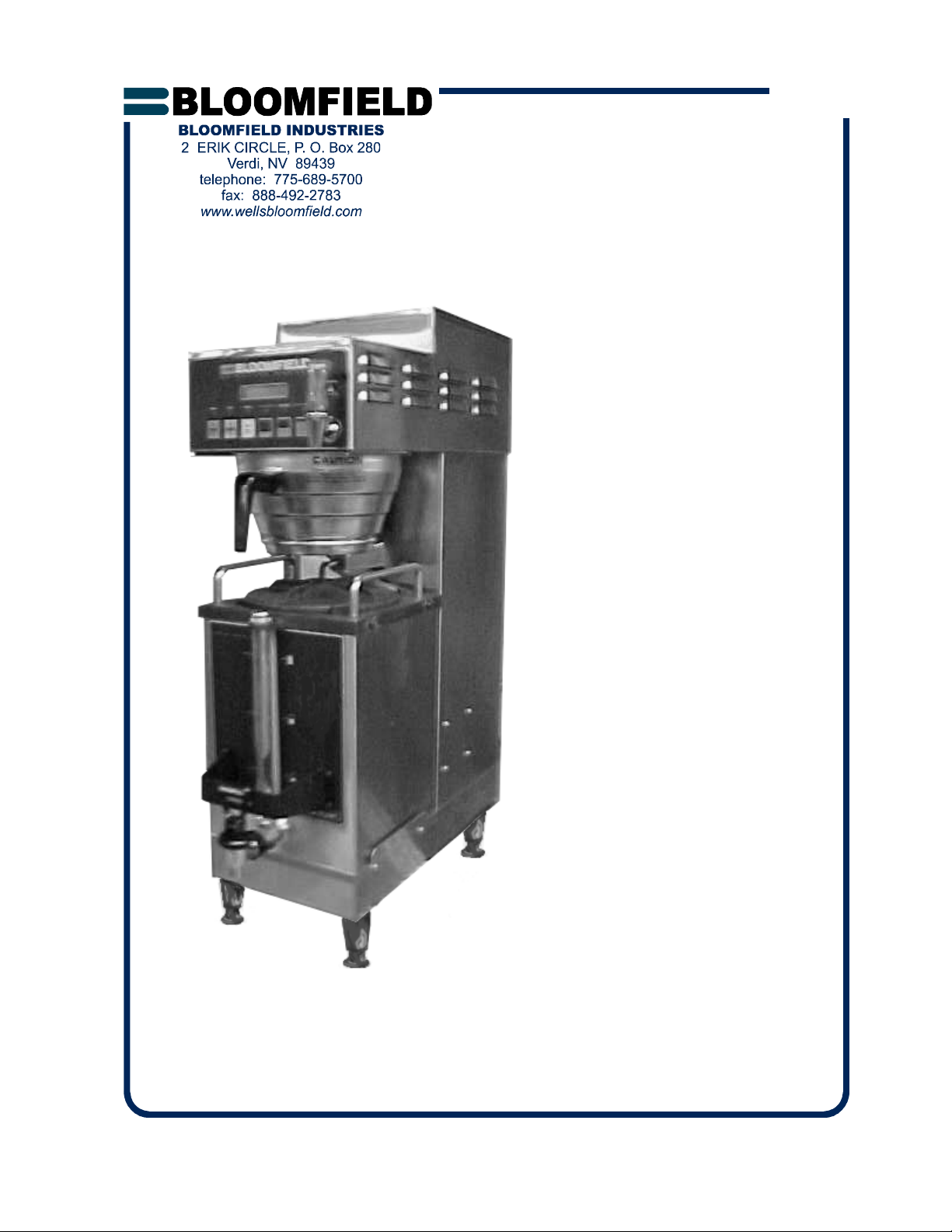
Model 9511J Satellite
Brewer
with
9340 Satellite
PRINTED IN UNITED STATES OF AMERICA
p/n 74735 Rev. C ECN-12817 M662J 050125 cps
Page 2

SHIPPING DAMAGE CLAIMS PROCEDURE
NOTE: For your protection, please note that equipment in
this shipment was carefully inspected and packaged by
skilled personnel before leaving the factory. Upon acceptance of this shipment, the transportation company assumes
full responsibility for its safe delivery.
IF SHIPMENT ARRIVES DAMAGED:
1. VISIBLE LOSS OR DAMAGE: Be certain that any
visible loss or damage is noted on the freight bill
or express receipt, and that the note of loss or damage
is signed by the delivery person.
2. FILE CLAIM FOR DAMAGE IMMEDIATELY:
Regardless of the extent of the damage.
3. CONCEALED LOSS OR DAMAGE: if damage is
unnoticed until the merchandise is unpacked, notify the
transportation company or carrier immediately, and file
“CONCEALED DAMAGE” claim with them. This
must be done within fifteen (15) days from the date the
delivery was made to you. Be sure to retain the
container for inspection.
Bloomfield Industries cannot assume liability for damage or
loss incurred in transit. We will, however, at your request,
supply you with the necessary documents to support your
claim.
xi
Page 3
TABLE OF CONTENTS
SPECIFICATIONS 1
FEATURES & OPERATING CONTROLS 2
PRECAUTIONS & GENERAL INFORMATION 3
INSTALLATION 4
AGENCY APPROVAL INFORMATION 5
OPERATION 6
CLEANING INSTRUCTIONS 11
SERVICING INSTRUCTIONS 12
TROUBLESHOOTING SUGGESTIONS 13
EXPLODED VIEW 14
PARTS LIST 15
WIRING DIAGRAM 16
Thank You for purchasing this
Bloomfield Industries appliance.
Proper installation, professional
operation and consistent
maintenance of this appliance will
ensure that it gives you the very
best performance and a long,
economical service life.
This manual contains the
information needed to properly
install this appliance, and to use,
care for and maintain or repair the
appliance in a manner which will
ensure its optimum perf ormance.
SPECIFICATIONS
ELECTRICAL SPECIFICATIONS
SATELLITE BREWER
MODEL WATTS VOLTS HZ CIRCUIT REQUIRED
9511J 3890 200V 50/60 3 + ground
3 PHASE WIRE TO CIRCUIT BREAKER
1
Page 4
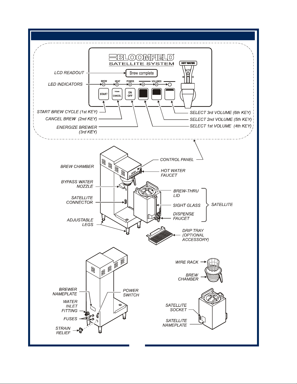
FEAT U R E S AN D OP E RATING CO N T R OLS
2
Page 5
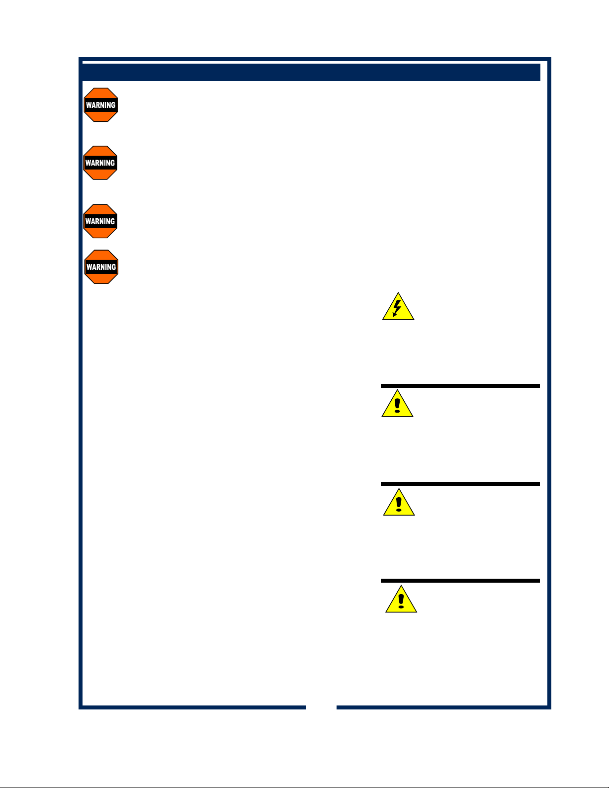
PRECAUTIONS AND GENERAL INFORMATION
WARNING: Electric Shock Hazard
All servicing requiring access to non-insulated components must be performed by qualified
service personnel. Do not open any access panels which require the use of tools. Failure to
heed this warning can result in electrical shock.
WARNING: Injury Hazard
All installation procedures must be performed by qualified personnel with full knowledge of all
applicable electrical and plumbi n g code s. Failure could result in property damage and
personal injury.
WARNING Electric Shock Hazard
Brewer must be properly grounded to prevent possible shock hazard. DO NOT assume a
plumbing line will provide such a ground. Electrical shock will cause death or serious Injury.
WARNING: Burn Hazard
This appliance dispenses very hot liquid. Serious bodily injury from scalding can occur from
contact with dispensed liquids.
This appliance is intended for commercial use only.
This appliance is intended for use to brew beverage products for
human consumption. No other use is recommended or
authorized by the manufacturer or its agents.
This appliance is intended for use in commercial establishments,
where all operators are familiar with the appliance use,
limitations and associated hazards. Operating instructions and
warnings must be read and understood by all operators and
users.
Except as noted, this piece of equipment is made in the USA
and has American sizes on hardware. Please note: Metric
hardware is used to mount the inlet (Fill) solenoid. All metric
conversions are approximate and can vary in size.
The following trouble shooting, component views and parts lists
are included for general reference, and are intended for use by
qualified service personnel.
This manual should be considered a permanent part of this
appliance. The manual must remain with the appliance if it is
sold or moved to another location.
CAUTION: Equipment
Electrical Damage
DO NOT plug in or energize this
appliance until all Installation
Instructions are read and followed.
Damage to the brewer will occur if
these instructions are not followed.
CAUTION: Burn Hazard
To avoid splashing or overflowing
hot liquids, ALWAYS use an
empty satellite before starting the
brew cycle. Failure to comply can
cause serious burns.
CAUTION: Burn Hazard
After a brew cycle, brew basket
contents are HOT. Remove the
brew basket and dispose of used
grounds with care. Failure to
comply can cause serious burns.
CAUTION: Burn Hazard
Exposed surfaces of the appliance
and brew basket may be HOT
to the touch, and can cause serious burns.
3
Page 6
INSTALLATION INSTRUCTIONS
READ THIS CAREFULLY BEFORE STARTING THE INSTALLATION
IMPORTANT:
To enable the installer to make
a quality installation and to
minimize installation time, the
following suggestions and tests
should be done before the
actual unit installation is started:
CAUTION: Equipment
Electrical Damage
DO NOT plug in or energize this
appliance until all Installation
Instructions are read and
followed. Damage to the
Brewer will occur if these
instructions are not followed.
CAUTION: Unstable
Equipment Hazard
It is very important for safety
and for proper operation that the
brewer is level and stable when
standing in its final operating
position. Provided adjustable,
non-skid legs must be installed
at each corner of the unit.
Failure to do so will result in
movement of the brewer which
can cause personal Injury and/
or damage to brewer.
NOTE: Water supply inlet line
must mee t cer tain minim u m
criteria to insure successful
operation of the brewer.
Bloomfield recommends 1/4"
copper tubing for installation of
less than 25 feet and 3/8" for
more than 25 feet from a 1/2"
water supply line.
UNPACKING & INITIAL INSPECTION
1. Unpack the unit. Inspect all components for completeness
and condition. Ensure that all packing materials have been
removed from the unit.
2. (See page 15) Remove the Top Cover and inspect the
internal components. Verify that all wiring and hoses are
connected and are properly seated. Verify that the Tank
Cover Assembly and Tank Cover Gasket are securely
installed. Reinstall top.
3. (See page 11) Verify that the Spray Head and Spray Head
Gasket are properly installed.
LEVELING THE UNIT
1. Verify that an adjustable leg is installed at each corner of the
brewer.
2. Set Brewer in its operating location.
3. Level the Brewer. A spirit level should be placed on the top
of the unit, at the edge, as a guide when making level
adjustments.
4. Level the unit from left to right and front to back by turning the
adjustable feet. Be sure all four feet touch the counter to
prevent tipping.
PLUMBER’S INSTALLATION INSTRUCTIONS
1. Brewer should be connected to a POTABLE WATER, COLD
WATER line. Flush water line before connecting to brewer.
2. DO NOT use a saddle valve with a self-piercing tap for the
water line connection. Such a tap can become restricted by
waterline debris. For systems that must use a saddle tap,
shut off the main water supply and drill a 3/16” (minimum) tap
for the saddle connection, in order to insure an ample water
supply. Remember to flush the line prior to installing the
saddle.
3. The brewer must be installed on a water line with average
pressure between 20 PSI and 90 PSI. If your water pressure
exceeds 90 PSI at anytime, a pressure regulator must be
installed in the water supply line to limit the pressure to not
more than 90 PSI in order to avoid damage to filters, lines
and solenoid.
4. A water shut-off valve should be installed on the incoming
water line in a convenient location (Use a low restriction type
valve, such as a 1/4-turn ball valve, to avoid loss of water
flow thru the valve.
4
Page 7

INSTALLATION INSTRUCTIONS (continued)
Y
5. NSF requires that the brewer be able to be moved for
cleaning underneath. A flex line or loops of copper tubing
will satisfy this requirement.
COPPER LOOPS OR FLEX LINES
(PROVI DED BY PLUM BER)
SHUT-OFF VALVE
(PROVIDED BY
PLUMBER)
SOLENOID
STRAINER
WASHER
WATER
SUPPL
6. In some areas, local codes require a backflow preventer
(check valve) to be installed on the inlet water line. If a back
flow preventer is used, you must install a water hammer
arrester in the incoming line, between the backflow
preventer and the brewer inlet, as far away from the brewer
as space will allow. This will relieve the excessive back
pressures that can cause faucet leaks and solenoid
malfunctions.
ELECTRICIAN’S INSTALLATION INSTRUCTIONS
REFER TO ELECTRICAL SPECIFICATIONS - Page 1
Check the nameplate to determine correct electrical service
required for the Brewer to be installed.
NOTE: Mod el 9511J requires a 200 Volt 3-Phase 20A circuit
(50/60 Hz, L1, L2, L3 plus earth ground). Circuit must
be capable of 3900 Watts.
This brewer meets
Standard 4 only when installed,
operated and maintained in accordance with the enclosed
instructions.
FLOW
AGENCY LISTING INFORMATION
NOTE: This equipment must
be
installed to comply with
applicable
federal, state and
local plumbing codes and
ordinances.
WARNING
ELECTRIC SHOCK
HAZARD:
Brewer must be properly
grounded to prevent possible
shock hazard. DO NOT
assume a plumbing line will
provide such a ground.
Electrical shock will cause death
or serious injury.
IMPORTANT: Do not attempt to
override the automatic tank fill
feature which requires that the
tank must be full of water to
start operations. Any attempt to
override this feature will void
the warranty.
IMPORTANT:
Before connecting to electricity,
make sure the Satellite Brewer
has been properly connected to
the water supply.
IMPORTANT:
Supply power must match
nameplate for voltage and
phase. Connecting to the
wrong voltage will damage the
brewer or result in decreased
performance. Such damage is
not covered by warranty.
STD 4
5
Page 8

OPERATION
OPERATING INSTRUCTIONS
IMPORTANT:
All satellite brewers are
tested and set at the
factory. If programming
adjustments are required,
refer to the Satellite Brewing System Programming
Manual (p/n/74781).
To over-ride the Brew
Wait mode, press and
hold the START key for
3 seconds when the
brewer is in Brew Wait
mode (i.e. when brew light
is flashing). The brew will
proceed immediately
regardless of water
temperature. This feature
should only be used when
testing water volume,
otherwise the brew will
proceed with the water
below the precise brew
temperature.
Note: the following
safety features have been
incorporated to prevent
multiple unattended
brews:
The brew key is
in-operative during a brew
cycle. This minimizes the
possibility of double
brewing.
When the “Brew” light is
on or flashing, repeated
pressing of the START
switch will be ignored,
(there will be a beep each
time it is pressed). A
Brew will only be activated
when the “Brew” light is
off.
1. Energizing the Brewer: When the POWER SWITCH is pressed to
ON, there will be a momentary flash of the power light. Energize
the brewer by pressing the ON/OFF key. The
brewer will start to fill the tank. With the proper
water supply the tank should be filled in about 2½
minutes. Once filled, the heating element will come
on until the proper tank temperature has been
reached Heating will take about 12 m i nu te s.
2. Brewing (Precise Temperature for Brewing™ — PTB™): In the
regular operating mode, the Satellite Brewer™
maintains the tank temperature within +/- .6ºC of
the brew temperature. Normally this will mean that
a brew will be started as soon as the START key is
pressed. However, there may be a slight delay if
the START key is pressed immediately after a brew
has been completed. If the tank temperature is
below the brew temperature, the brew will be
delayed, going into the “Brew Wait” mode, with the
brew light flashing. As soon as the correct
temperature is reached the brew will commence with the brew light on
continuously during the brew. During the brew cycle, if the BREW key
is pressed, it will be ignored. Only when the brew is complete can
another brew be started.
3. Brew Cancel: To cancel a brew in progress, press the CANCEL
KEY: two beeps will sound and the “Brew” light
will go out. Water flowing to the brew chamber
will be stopped immediately, but if there is
already water in the brew chamber, it will take a
few moments before this drips through as
coffee.
4. Normal Operation (Non Brewing): When the unit is not brewing,
the Satellite Brewer maintains the water temperature at the Precise
Temperature for Brewing™ (PTB™). The heating element will
cycle on and off automatically to maintain this temperature.
5. After Hours Mode: If no brew is detected for a pre-selected length
of time, the brewer will enter the After Hours mode. Temperature
will be allowed to drop to save energy. Pressing the START key
returns the brewer to normal operation.
6
Page 9

USER’S GUIDE
OPERATION (continued)
1. Remove the brew chamber from under the spray head.
Place one (1) genuine Bloomfield paper filter into the brew
chamber. Add your choice of pre-measured ground coffee.
Shake the brew chamber gently to level the coffee.
Slide the brew chamber back into place.
PAPER
FILTER
BREW
CHAMBER
2. Place an empty satellite under the brew chamber.
3. To begin the brew cycle, press desired VOLUME key, then press
the START key. Hot water will start spraying over the coffee, and
brewed coffee will start filling the decanter. When the coffee
stops flowing from the brew chamber, the fresh coffee is ready to
serve.
NOTE: Brewing will not begin until the Precise Temperature for
Brewing™ has been reached. (See page 6)
4. At the end of the brew cycle, the view screen will read “Brew complete”.
Brew complete
After all dripping has stopped, remove
the brew chamber from the brewer.
Discard the used paper filter and
product.
5. The brewer is now be ready to begin another brewing cycle.
WARNING:
Burn Hazard.
This appliance
dispenses very hot liquid.
Serious bodily injury from
scalding can occur from
contact with dispensed
liquids.
CAUTION:
Burn Hazard
To avoid splashing or
overflowing hot liquids,
ALWAYS use an empty
decanter before starting
the brew cycle. Failure to
comply can cause serious
burns.
CAUTION:
Burn Hazard
After a brew cycle, brew
chamber contents are
HOT. Remove the brew
chamber and dispose of
used filter and grounds
with care. Failure to
comply can cause serious
burns.
CAUTION:
Burn Hazard
Exposed surfaces of the
appliance, as well as brew
chamber and decanter
may be HOT to the touch,
and can cause serious
burns.
7
Page 10

OPERATION (continued)
PROGRAMMING FEATURES AND OPTIONS
1. View Water Temperature in Tank: To view the water temperature on the screen, the
brewer must be ON, and not brewing or in the filling mode. Press and hold the 4th key, and
depress the 6th key. The actual water temperature will be displayed for 3 seconds.
2. Daily Brew Count: The brewe r maintains a count of the number of completed brews for a 7-day
period. To access the count, turn the brewer OFF. In the OFF mode, press and hold the
CANCEL key for 3 seconds. The current day and brew count will be displayed. Depress the
ON/OFF key repeatedly to view each preceding day. When all 7 days have been displayed a
7-day total will be displayed. If you wish to exit the daily brew count before viewing all of the
days, press CANCEL key.
3. ON/OFF – Non Automatic Timer: To turn the brewer OFF, press the ON/OFF switch: 2 beeps
will be heard and the brewer will be turned OFF, indicated by all lights being off. To turn the
brewer ON, press the ON/OFF switch: 2 beeps will sound, all lights will flash once, then the
“Power” light will remain on, (the “Heat” light may come on if water temperature is too low).
4. ON/OFF – Automatic Timer Feature: The factory prog rammed brewer has the automatic
timer turned off. To set the automatic timer, refer to the Satellite Brewing System Programming
Manual, “Time Functions” Menu. If the Automatic Timer feature is programmed off, the brewer
can be turned on and off by depressing the ON/OFF switch, as noted above.
* When the Automatic Timer feature is programmed ON, the E-Max will turn on and off
automatically, at a programmed time, Monday to Friday; with a separate on and off
programmed time schedule for Saturday and Sunday.
* Temporarily Overriding the Automatic ON/OFF function. While in the automatic timed OFF
mode the brewer can be started by depressing the ON/OFF switch. The brewer will remain
ON until the automatic programmed off time, when it will turn OFF and resume normal
automatic timed functioning. Similarly, if turned OFF during the automatic timed ON mode
the brewer will remain OFF until the next programmed on time, when it will turn on and
resume normal automatic timed functioning.
5. Automatic Start-Up in Previous Mode: If the brewer automatic timer is OFF (the factory
setting) and power is disconnected, the brewer will start up when power is restored, in the mode
it had been in prior to the power disconnection. If the brewer has the timer setting ON and
power is disconnected, the brewer will start up in the mode that it should be in at the time the
power is restored.
6. Viewing Programmed Brew Volume: The brewer can have up to 4 different brew volumes.
When a volume other than the standard, or first brew volume, is selected, the brewer will
complete that volume and then automatically reset to the standard, or first brew volume. With
the brewer ON, press and hold the CANCEL key. The 1st, or standard, volume will be displayed
for 3 seconds (i.e. Volume #1 64 oz)., and then the day and time will be displayed.
7. Changing Brew Volume: As outlined above, display the current brew volume and, before the
display changes to day and time, depress the CANCEL key momentarily, (not for 3 seconds).
The next programmed brew volume (e.g. Volume#2 32 oz.) will be displayed on the LCD for
3 seconds, after which the display will return to the day and time. Repeatedly press CANCEL
while programmed volumes are shown to view all brew volumes. (If there is only one brew
volume programmed, only that volume will be displayed.) The last brew volume displayed, before
the LCD returns to the day and time, is the brew volume that the brewer will brew the next time
the START switch is depressed. When a brew volume other than the 1st brew volume is
selected, the brewer will complete the brew then return to the 1st or standard brew volume
automatically.
8
Page 11

OPERATION (continued)
8. Clock
A. Time – Battery Backup. The brewer has a battery backup system which will maintain the
proper time during power failures, or when the brewer is unplugged (even for very prolonged
periods of time). Normally there will not be a need to set the time except fo r Daylight Saving
Time changes, or moving the brewer to different time zones.
B. Changing Day and Time: To change time, turn the brewer OFF. Press the 2nd key twice
followed by the 1st key twice to access the time change mode, (i.e. press CANCEL, CA NCEL,
START, START). In the time change mode the screen will read “Day:” followed by the current
day setting. Use the 6th key to advance the day, or the 5th key to reverse. When day has
been properly set, press the 3rd key. The screen will now read “Time:” with the set time on
the screen, the hour and am or pm flashing. Use the 5th key to go back or the 6th key to
advance the hour, making sure that the am or pm is correct. When the hour and am/pm is
correctly set, press the 3rd key, and the screen will read “Time:” with the set time on the
screen, minutes flashing. As previously use the 5th or 6th keys to adjust the minutes, and
press the 3rd key when complete. The brewer will return to the off mode. (Changing time can
also be done in the regular programming mode. Consult the Programming Manual)
C. After Hours™: Consult the Programming Manual to set the After Hours™ mode.
The factory programming has the After Hours™ mode turned OFF. The After Hours™ can be
programmed to com e on from 1 to 6 ho ur s after the last brew. When the brewer goes into
the After Hours™ mode, the water in the tank will be allowed to drop from the normal brewing
temperature and will reheat less frequently – this feature saves energy and extend component
life. While in the After Hours mode, the power light will flash continuously. When the START
switch is pressed the brewer automatically reverts back to normal operation, heating the water
to the Precise Temperature for Brewing™ (PTB™), before starting the brew. (The power light
will be on continuously and the Brew light will flash until the correct water temperature is
reached.)
9. Countdown Quality Timer™: The brewer factory programming has the Cou ntdown Quality
Timer™ turned OFF. Consult the Programming Manual to activate the Countdown Quality Timer™
feature:
10. Pulse or Pre-Infusion Volume Options: To set these features, refer to Programming
Manual, Brew Settings Menu. If a particular brew volume has utilized the pulse or pre-infusion
option, that volume will be displayed with an asterisk (*) after the volume. As an example
“Volume#2 64oz*” would indicate that the second programmed brew volume has utilized the
pulse or pre-infusion program options.
11. Keypadlock™:
Programming Manual, Machine Settings Menu. If the Keypadlock™ feature is activated,
there will be no response by the brewer when the keys are depressed (except for the beep after a
key is depressed). To temporarily “unlock” the keypad, press and hold the CANCEL key for 6
seconds. A beep will be heard indicating the keypad is now “unlocked”, — a brew can be initiated,
warmer plates turned on or off, etc. The keypad will remain unlocked until the brew is completed,
then automatically return to keypadlock™ mode. If a brew is not initiated 60 seconds after
“unlocking”, the system will time out and return to the “locked” position.
This feature is OFF in the standard factory settings. To set the feature refer to
9
Page 12

OPERATION (continued)
12. View Filter Statistics: To view filter statistics, turn the brewer off. Press and hold the 1st key
(START), and depress the 3rd key (ON/OFF). Total water volume will be displayed (TotalVol.).
Press the 3rd key to view the Filter Life (FltrLife:). Press the 3rd key to view the percentage of
the filter that has been used.
13. Diagnostic Messages – Programmed Safety Features: When the brewer senses a problem,
it will automatically turn off all valves, flash lights, display the message “Call For Service” and
display one of the messages below. (Additionally : a service phone number may appear if it has
been programmed into the system.)
* To reset the brewer it can be re-energized (or press and hold CANCEL for 3 seconds for all
faults except the Valve Fault, which must be reset by re-energizing). The brewer will try to
re-start, but if the same problem persists, the appropriate error message will appear again.
Consult the Trouble Shooting section to determine how to solve the problem.
A. “Probe/Heater Error”: Overheating Detection (1): If the heating element is on for 5 minutes
and the temperature does not change by +1°C in the five minute period, the unit will go
into the Over Temperature Mode with all lights flashing. When in this mode the brewer turns
off the heating elements, the solenoid valves are turned off; the switches disabled; (and all
lights flashing continuously). The LCD display will read “Probe/Heater Error”, followed by the
message “Call for Service”, and then the service phone number (if it has been entered into
memory). To reset press and hold CANCEL for 3 seconds, or re-energize the brewer.
(Possible causes of problem: high limit needs to be re-set; defective high limit, element, triac,
water level probe or control board.)
B. “Overheat Error”: Overheating Detection; If the brewer senses a temperature over the
Maximum Temperature set in the program (factory set at 208ºF or 98ºC) it will go into the over
temperature mode as above with all lights flashing, except the LCD will read “overheat error”,
and “Call for Service”. To reset press and hold CANCEL for 3 seconds, or re-energize the
brewer. (Possible cause of problem is a defective triac, temperature probe or related wiring
and connections.)
C. “No Water Sensed” — Time-Out —Inlet Valve: When filling for the first time, the inlet valve
will remain open for 4¼ minutes, (the screen will read “filling…”). If water is not detected at
the end of this time the brewer will shut down with the message “no water sensed”. The
valves and all elements are turned off, and the Brew and Pow er light flash alternately with the
Heat light, until the brewer is reset. To reset press and hold CANCEL for 3 seconds, or
re-energize the brewer. (Possible causes of the problem are: no incoming water; slow flow of
incoming water (i.e. less than 45 oz/minute); sensor not reading (check for placement,
connections or lime scale).
D . “No Water Sen s ed ” — Time-Ou t – Brew Valve: During the brew the inlet solenoid valve
cycles on intermittently to maintain the proper level in the tank. If the valve is open for
60 seconds without water being detected at the proper level, the brewer will go into the same
error mode as above (“no water sensed”). To reset press and hold CANCEL for 3 seconds,
or re-energize the brewer. (Possible causes of the problem are: no incoming water; slow flow
of incoming water, sensor not reading, etc.).
E. Keyswitch Locked: If a key switch is depressed for 10 seconds this error message will
occur. Lights will flash alternately and the brewer will turn off all valves and elements. Press
and hold the CANCEL key for 3 seconds to reset the brewer (or re-energize the brewer). If
the problem re-occurs this indicates a defective switch on the key pad.
F. “Valve Fault”- Faulty Valve Detection: When an electric or switching problem is detected
with either the inlet or brew valve the brewer turns off all elements and valves and displays
“valve fault…”. All of the lights will be turned on. Before re-setting the brewer the valves
must be checked to determine the problem. The brewer must be re-energized to re-set,
(pressing CANCEL for 3 seconds will not reset a valve fault).
10
Page 13

CLEANING INSTRUCTIONS
PROCEDURE: Clean Coffee Brewer
PRECAUTIONS: Disconnect brewer from electric power.
Allow brewer to cool.
FREQUENCY: Daily
TOOLS: Mild Detergent, Clean Soft Cloth or Sponge
Bristle Brush
1. Disconnect brewer from electric power.
Allow brewer to cool before cleaning.
2. Remove satellite.
3. Remove and empty brew chamber.
4. Remove the spray disk from the brew head:
Press up on the spray disk ears, then turn the disk to the left
to unlatch. Remove the gasket from inside the brew head.
5. Wipe inside of brew head and area around the brew head
with a soft clean cloth or sponge moistened with clean water.
If insert is removed from spout, be sure it is properly
reinstalled.
6. Wash the spray disk in a sink using warm water and a mild
detergent. A bristle brush may be used to clear clogged
spray holes. Rinse the spray disk with clean water and allow
to air dry.
7. Wash the brew chamber in a sink using warm water and a
mild detergent. A bristl e brush may be used to clean the
inside. Rinse with clean water and allow to air dry.
8. Wipe the exterior of the brewer with a soft clean cloth or
sponge moistened with clean water.
10. Reinstall the gasket INSIDE the brew head, then reinstall the
spray disk.
11. Reinstall the brew chamber.
12. Wipe the interior and exterior of satellites with a soft cloth
dampened with clean water and a mild detergent. Rinse by
wiping with a clean cloth dampened with clean water.
Procedure is complete
CAUTION:
Burn Hazard
Brewing and serving
temperatures of coffee are
extremely hot.
Hot coffee will cause
serious skin burns.
CAUTION:
Electric Shock
Hazard
Do not submerge or immerse
brewer in water. Do not pour or
splash water into or over air
vents or control panel.
CAUTION:
Electric Shock
Hazard
Do not submerge or immerse
satellite in water.
IMPORTANT:
DO NOT use steel wool, sharp
objects, or caustic, abrasive or
chlorinated cleansers to clean
the brewer or satellites.
11
Page 14

SERVICING INSTRUCTIONS — DE-LIMING HEATER TANK
CAUTION - CHEMICAL
BURN HAZARD
De-liming chemicals are caustic.
Wear appropriate protective gloves
and goggles during this procedure.
CAUTION - CHEMICAL
BURN HAZARD
Never siphon de-liming chemicals
or solutions by mouth.
This operation must only be
performed by qualified and
experienced service personnel.
IMPORTANT: DO NOT spill,
splash or pour water or de-liming
solution into or over any internal
component other than the inside of
the water tank.
IMPORTANT: DO NOT allow any
internal components to come into
contact with the de-liming solution.
Take care to keep all internal
components dry.
NOTE: Repeat steps 4 thru 7 as
required to remove all scale and
lime build-up.
NOTE: Normally, silicone hoses
do not need to be de-limed.
Should de-liming hoses become
necessary, Bloomfield Industries
recommends replacing the hoses.
1. Disconnect brewer form the electrical supply. Turn off
the water supply and disconnect water supply from the
brewer inlet fitting.
2. Remove the top panel or top warmer section to gain
access to internal components.
3. Disconnect water level sensor and water temperature
sensor from the controller. On 120V units, slip hi-limit
thermostat from under its holder clip. Disassemble the
three lid clips and lift the lid off of the water tank. Store
lid assembly in a safe location.
4. Mix de-liming solution according to the manufacturer’s
directions. Add the de-liming solution to the water tank.
Set lid assembly back on tank. Allow to sit for 30
minutes, or as directed by the manufacturer.
5. At end of soaking period, remove lid assembly from tank.
Thoroughly rinse interior components of lid assembly
with clear water. Wipe temperature sensor and water
level sensor with a clean, soft cloth. Store lid assembly
in a safe location.
6. Using a stiff bristle brush, scrub the coils of the heating
element and the interior surfaces of the water tank.
7. Siphon the used solution and loose lime/scale into an
appropriate container. Dispose of the used solution as
required by local ordinances.
CAUTION: Never siphon by mouth. Serious injury can
result!
8. Fill the water tank with clean tap water. Rinse
thoroughly, then siphon the rinse water into an
appropriate container for disposal. Again, take care to
keep all internal components dry.
9. Reassemble the tank lid to the water tank. Make sure
the gasket is properly attached to the lid before
assembling the lid clips. Re-connect the water level and
temperature probes, then reinstall the hi-limit thermostat
(if removed). Verify that all internal components are dry,
then reinstall the top panel.
10. Reconnect brewer to water and electrical. Run and
discard at least three full decanters from the faucet.
Install the brew chamber without filter paper or grounds,
then run and discard at least three full decanters as
normal brew.
11. Brewer is ready to use.
12
Page 15

TROUBLESHOOTING SUGGESTIONS
If the brewer goes into the error diagnostic mode as outlined below, it will likely be necessary to
reset the brewer in order to test individual components. Note the reset procedure below:
* For the first four error modes, press and hold CANCEL for 3 seconds, or RE-ENERGIZE the
brewer by disconnecting from electric power for 5 seconds, then reconnecting.
* From “VALVE FAULT”, the brewer must be RE-ENERGIZED! Using the CANCEL button will not
reset the brewer from “Valve Fault”.
The Test Program will also assist in isolating and testing specific components. As an example to test
the three main components in the heater system, go to the test program and proceed to turn the
“heater on”. Use a meter or test light to determine if power is getting to and from: the triac, the high
limit and the element.
ERROR MESSA G E
1. “Probe/Heater”
Error
RESET by
holding
CANCEL switch
for 3 seconds
2. “Overheat” Error
RESET by
holding
CANCEL switch
for 3 seconds
3. “No Water
Sensed” Error
RESET by
holding
CANCEL switch
for 3 seconds
4. “Keyswitch
Locked” Error
RESET as
above
5. “Valve Fault”
Error
RESET by
disconnecting/
reconnecting
electric power
CAUSE
Controller has turned
heating element on for 5
minutes without sensing a
+2ºF change in water
temperature.
Water temperature has
exceeded Maximum Water
Temperature programmed
into “Machine Settings”
menu.
Inlet valv e en er gi z e d b ut
no water is sensed during
regular operation for 60
seconds; or.
no water sensed during
start-up (manual or timed)
for 4½ minutes.
A switch on the keypad
has been held down for
more than 10 seconds.
Detecti on of a pro bl em w it h
the valve switching syst em,
or with the wiring to the
valves.
SUGGESTIO NS FO R RE ME DI AL A CTI ON
1. Temp Probe may not be connected properly, or may be defective. CHECK &
CORRECT. To test probe, go to Test Program and view probe value. A value
of over 1 55 ind ic ates a defe cti v e pro be; a valu e of und er 15 in dicat e s a ba d
connection of the probe to the board. With an ohmmeter measure resistance of
probe. At 212ºF, resistance is approx. 2,000
temperature
2. May be boiling due to high altitude (boiling point below Brew Temp.) or Triac
has failed ON and hi-limit has interrupted power to heating element. REDUCE
BREW TEMP. CHECK TRIAC; REPLACE IF DEFECTIVE.
3. Heating element defective. CHECK ELEMENT; REPLACE IF DEFECTIVE.
4. Hi-limit thermostat may be cutting out at too low a temperature. CHEC K HI LIMIT THERMOSTAT; REPLACE I F DEFECTIVE. (Note; hi-limit will reset
itself if allowed to cool by 30ºF, making troubleshooting a challenge as the brewer
cools then functions normally.)
5. Heati n g el em e nt m a y b e e nc rusted with lime or sc a le b uil d -u p. D ELIME BREWER
AS DETAILED ON PAGE 16.
1. Brew Tem perature may be set too close to Maximum Temperature. Brew
Temperature should be at least 5ºF below Maximum Water Temperature.
LOWER BREW T EMPERATURE or R AISE MAXIMUM T EMPERATURE
(Software versions after May, 1999 enforce the 5ºF differential)
2. Triac has failed ON; element continues to heat even when controller is OFF.
CHECK TRIAC; REPLACE IF DEFECTIVE.
3. Temp Probe defective. See probe test procedure in Item #1 above. CHECK
PROBE; REPLACE IF DEFECTIVE.
1. Sleeve on water level sensor is too long, or sensor is not pushed down fully.
Sensor shou l d ext e nd b e y on d sl ee ve a m i ni m u m of ¼” t o a ma x im u m of l”.
REMOVE TANK LID, CUT SLEEVE TO PROPER LENGTH. ENSURE SENSOR
IS PUSHED DOWN ALL THE WAY.
2. Wiring to water level sensor disconnected or defective; or, sensor pulled out of
tank. CHECK & CORRECT.
3. Water level sensor may be encrusted with lime build-up. CLEAN SENSOR.
4. Water supply may be OFF. CHECK & RESTORE WATER SUPPLY.
1. Switch has been accidentally held for 10 or more seconds. RELEASE SWITCH
2. Defective keypad. PRESS & HOLD “CANCEL” FOR 3 SECONDS. Observe
brewer to determine if problem persists. (Note: available on software versions
MFW 275 Rev. 3.4 and later versions only).
1. Wiring to either inlet or outlet valve not properly connected. CHECK WIRING AND
CONNECTIONS.
2. The co ntr o ll er h as t w o swit c h es f or e ac h v al v e a n d on e or b ot h has be e n det ec t ed
as failing ON. (This prevents the brewer from operating u nless both switches ar e
working properly.) REPLACE CONTROLLER.
,
probe is defective.
Ω
. If less than 1800Ω at roo m
13
Page 16

EXPLODED VIEW
14
Page 17

ITEM SERVICE # DESCRIPTION QTY
1 COVER 1
2 ASSEMBLY UPPER HOUSING 1
3 HOUSING LOWER 1
4 PLATE ASSEMBLY BOTTOM 1
5 PANEL FRONT 1
6 BASE ASSEMBLY 1
7 MOUNTING PLATE, CONTACTOR 1
8 82936 SWITCH ROCKER ON/OFF 125/250V 1
9 84710 TANK ASSEMBLY 3 GAL. 1
10 83313 THERMISTOR 1
11 83312 THERMO HI-LIMIT DBL POLE 1
12 84063 GROMMET .510 O.D. x .250 I.D. 1
13 83499 GASKET TANK COVER 1
14 85976 PROBE ASSEMBLY WATER LEVEL 1
15 83532 SLEEVE WATER LEVEL PROBE 1
16 83504 COVER ASSEMBLY TANK 1
17 85086 FILL TUBE 90º BEND L=14.5 1
18 SCREW PAN PHL 10-32 x 1/2 4
19 86256 TANK CLAMP 4
20 84715 TUBE SILICONE ø .312 x 11"L (FAUCET) 1
21 83537 TUBE SILICONE ø .312 x 9"L (OVERFLOW) 1
22 83384 TUBE SPRAY HEAD 2.3"L SS 1
23 82390 GROMMET .375 I.D. 1
24 83533 HARNESS WIRE WATER LEVEL PROBE 1
25 83553 TUBE SILICONE 72" DRAIN 1
26 85928 TUBE SILICONE ø .50 I.D. x 5" 2
27 BRACKET OUTLET VALVES 2
28 85094 TUBE SILICONE ø .312 x 32"L (FILL TUBE) 1
29 83388 VALVE WATER OUTLET ADJUSTABLE 2
30 SCREW TRS PHL 8-32 x 1/2 SS 14
31 D 20002-3 SCREW PAN PHL 10-32 x 5/16 SS 4
32 8942-92 NUT KEP 8-32 12
33 83152 ELBOW SPRAYER 1
34 84711 BOARD SET CONTROL 9511 120V 1
35 83414 SHIELD HI-LIMIT 1
36 84748 OVERLAY DECAL KEYPAD 1
37 84215 FAUCET HOT WATER 1
38 82215 GASKET SPRAY HEAD 1.5 I.D. 1
39 82727 DISK SPRAY HEAD EMBOSSED 1
40 83571 INSERT SPRAY HEAD 1
41 66385 FITTING CONDUIT STRAIGHT 1
42 84712 ELEMENT HEATING 3600W 200V 3PH 1
43 60310 TERMINAL BLOCK 4 POLE 75A 1
44 83107 FEET RUBBER BLACK (PK OF 4) 1
45 83098 LEG PLASTIC BLACK 4" W/FLANGE 4
PARTS LIST
ITEM SERVICE # DESCRIPTION QTY
46 85987 ASSY WATER INLET SOLENOID 120V 1.0GPM 1
47 83415 NUT HEX 6-32 x 1" ALUM 2
48 SCREW PAN 4mm x 6mm 2
49 85275 CONTACTOR MINI 1
50 85162 TRANSFORMER 200V 1
51 8543-52 SCREW #8 x 3/8" SHEET METAL 22
52 83059 GUIDE BASE 2
53 83100 ASSEMBLY BREW CHAMBER (.187 HOLE) 1
53A 8812-73 CLIP BREW BASKET 1
53B 8707-2 HANDLE BLACK 1
53C 8707-3 SCREW HEX 10-32 x 5/16 1
53D 8706-6 RACK WIRE BREW CHAMBER 1
53E 83101 BREW CHAMBER 1
54
55
56
57
58
59 82738 SPOUT ASSEMBLY 1
60 85929 TUBE SILICONE ø .312 x 13.5"L (BYPASS) 1
61 82681 WASHER .47 I.D. x 1.12 O.D. SS 1
62 8043-11 ELBOW OUTLET 1
63 83795 FUSE HOLDER 3
64 83794 FUSE 5A 3
65 COVER BASE 1
66 83046 CONNECTOR ASSEMBLY 1
67 8543-23 NUT TNE #8 Zi 22
68 55313 NUT 10-32 SS 1
69 85204 TUBE SILICONE ø .312 x 3" 1
70 BRACKET CONNECTOR 1
71 8543-69 BUSHING SHORTY HEYCO 1
72 83570 INSERT BYPASS
73 83359 WASHER FLARE TANK DRAIN 1
74 83380 TUBE ASSEMBLY COPPER 2.25"L 1
75 87780 CONTACTOR 3 PH 240V 40A 1
76 SCREW #6-32 x 38" SS 2
77 WASHER FLAT #8 SS 2
78 8540-30 ELBOW POLYPROPYLENE 1
79 BRACKET, TANK HOLDING 2
80 86629 STRAP C-CLAMP 2
81
82 67662 FITTING 3/8 BARB x 3/8 NPT 1
83 66575 VALVE SHUTOFF DRAIN 1
84 83605 ELBOW MALE 5/8 x 3/8 90º 1
85 84382 SWITCH ROCKER HI-TEMP 1
15
Page 18

WIRING DIAGRAM
16
Page 19

NOTES
17
Page 20

Bloomfield Industries proudly supports CFESA
Commercial Food Equipment Service Association
Bloomfield Industries, Inc.
Division of Carrier Commercial Refrigeration
In US and Canada
Telephone: 775-689-5700
Fax:
Fax:
888-492-2783
800-356-5142 ()
for orders only
website: www.wellsbloomfield.com
PRINTED IN UNITED STATES OF AMERICA
 Loading...