

Page 1
BLOOMFIELD INDUSTRIES
2 ERIK CIRCLE, P. O. Box 280
Verdi, NV 89439
telephone: 888-492-2782
fax: 888-492-2783
www.wellsbloomfield.com
727
CONVERSION INSTRUCTION
Convert Model 9465 KFT to
Mechanical Switches
KIT # 87439 - Convert Model 9465KFT Electronic Portion
Control to Mechanical Switches with Portion Control
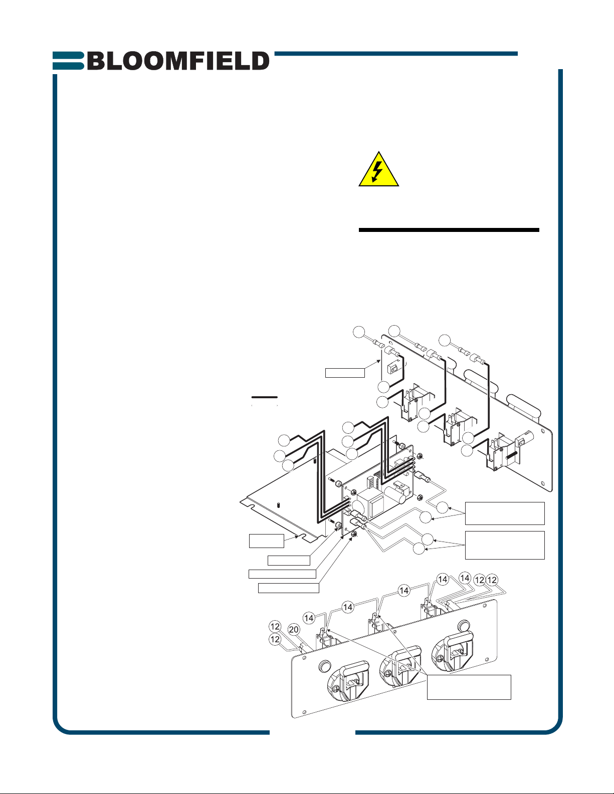
1. Disconnect unit from electric power.
2. Remove portion control assembly from front of unit.
3. Refer to 9465KFT Wiring Diagram, page 2. Mark wires to
control board, then disconnect wires from board. Discard
old board.
4. Unfasten contactor from mounting bracket. Remove and
discard old bracket. Install new bracket and remount
contactor. Mount portion control board to new bracket.
5. Locate red wire #12 and blue wire #13. Determine a
position on each wire that will comfortably reach the
portion control board.
Cut wire #12 at the determined
location, strip insulation and
crimp a provided female terminal
(small barrel) to each wire.
Connect to L2 and VALVE
COMM on portion control
board.
NEW WIRING HARNESS
EXISTING WIRES
SWITCH PANEL
Cut wire #13 at the determined
53
51
55
RED
BROW
BLUE
N
location, strip insulation, twist
both wires together and crimp on
provided female terminal ( large
barrel). Connect to L1 on portion
control board.
6. Locate 2 ea. blue wires #14 near
front of unit and remove tape
from terminals.
7. Connect provided wiring harness
to switch panel and portion
control board.
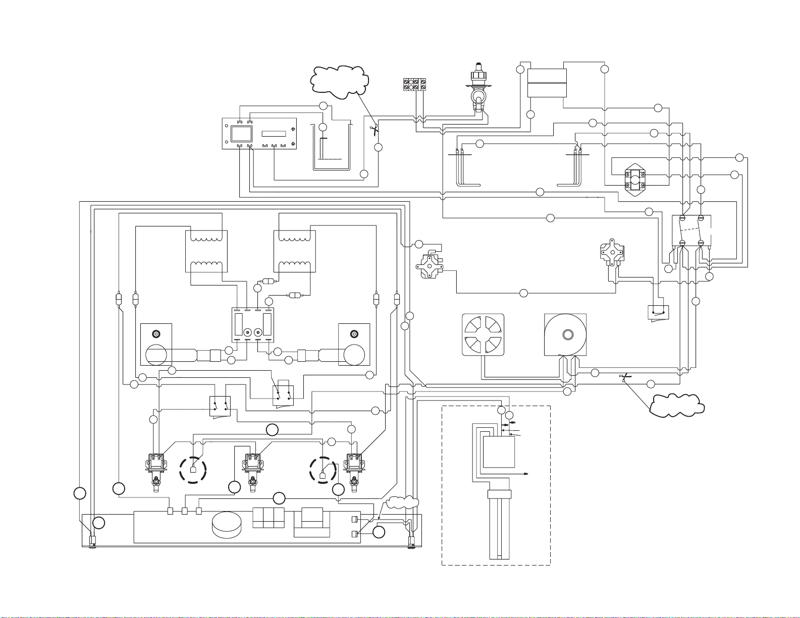
8. Refer to revised 9465 Wiring
Diagram, page 3. Connect
CONTACTOR
BRACKET
SPACER 4 places
PORTION CONTROL BOARD
NUT 10-32 KEPS 4 places
existing wires to new switch
panel and portion control
board per diagram.
9. Assemble switch panel to unit.
RED
WHITE
Connect unit to electric power
and test for proper operation.
10. Program portion control
option as required.
(see page 4)
CAUTION
ELECTRIC SHOCK HAZARD
Disconnect appliance from electric
power before beginning this
conversion.
IMPORTANT:
This procedure must be performed by
factory authorized personnel. All wiring
terminal attachment must be performed
in accordance with the wire terminal
manufacturer’s specifications using
correct tooling.
23
RED
N
W
52
51
BRO
W
N
RED
RED
54
53
BROW
BRO
W
33
BLUE
N
N
BLUE
56
BLUE
55
R
ED
RED
12
12
BLUE
BLU
E
13
13
REMOVE TAPE FROM 2 TERMINALS
ON BLUE WIRE #14
CONNECT TO CONNECTOR
OF LEFT AND CENTER SWITCHES
CUT RED WIRE #12
CRIMP ON 2 FEMALE TERMINALS
CONNECT TO &
ON PORTION CONTROL BOARD
CUT BLUE WIRE #13
CONNECT ENDS AND CRIMP ON
FEMALE TERMINAL
CONNECT TO ON
PORTION CONTROL BOARD
FRONT
52
54
32
RED
BRO
BLUE
56
BLUE
L2 VALVE COMM
L1
RED
Page 1 of 4
p/n 87439A Rev. (-) ECN-12956 I727 051114 cps
Page 2
Page 2 of 4
12
RED
BREW
LIGHT
20
WHITE
WHITE
32
ORANGE
DISPENSE
VALV E
(LEFT)
32
RED
LEFT SWITCHES
CONTROL BOARD
BLACK
YELLOW
LEADS
AUGER MOTOR
(LEFT)
+
-
12
21
RED
22
CENTER SWITCH
LIQUID LEVEL
BLACK
208/240V
LEFT
TRANSFORMER
24V
CONTROL
RED
SOLENOID VALVE
ON/OFF SWITCH
BROWN
RIGHT SWITCHES
COM
MAX
NC
L1
L2
26
ORANGE
25
SPEED
BOARD
-++
-
RED
27
28
WHITE
4
1
2
5
WHITE
SERVE
SANITIZE
DISPENSE
(CENTER)
23
PORTION CONTROL BOARD
GREEN/YELLOW
NO
BLACK
208/240V
RIGHT
TRANSFORMER
24V
BROWN
RED
29
30
4
1
2
5
BLUE
14
VALV E
BLUE
33
CUT WIRE #13
TWIST TOGETHER
ADD TERMINAL
18
WHITE
19
LIQUID
LEVEL
PROBE
BROWN
BLACK
YELLOW
LEADS
AUGER MOTOR
(RIGHT)
+
-
WHITE
24
12
RED
BLUE
14
L2
L1
17
31
BLUE
BLACK
DISPENSE
TERMINAL
BLOCK
13
33
VALV E
(RIGHT)
14
BLUE
JUMPER
BLUE
12
POWER
LIGHT
INLET
L2 RED
L1 BLACK
VALV E
BLACK
12 GA
DISPENSE TEMP
THERMOSTAT (LEFT)
WHITE
20
3
2
1
RED
12
RED
ILLUMINATED
5
HTG ELEMENT
(LEFT)
240V 3000W
FAN
RED
DOOR
RED
12 GA
12 GA
BLACK
BLACK
BLACK FAN LEADS
12
RED
14
BALLAST
RED
LAMP
6
BLUE
15
BLUE
(2) WIRE NUTS
WHITE
BLACK
WIRE NUT
YELLOW
L2
LINE
L1
LINE
POWER
SWITCH
1
HTG ELEMENT
(RIGHT)
240V 3000W
13
BLUE
13
BLOWER
T2
LOAD
T1
LOAD
RED
12 GA
TANK TEMPERATURE
THERMOSTAT (RIGHT)
14
BLUE
7
12 GA
RED
BLACK
12 GA
2
10
RED
12 GA
9
RED
12 GA
8
4
BLACK
12 GA
BLACK
12 GA
T1
3
2
1
3
4
HI-LIMIT
RED
11
T2
CONTACTOR
L2
1
2
12
RED
11
RED
HEATER
SWITCH
RED
12
CUT WIRE #12
ADD TERMINALS
L1
16
BLACK
14
BLUE
WIRING DIAGRAM
9465KFT
P/N 76312
Page 3

Page 3 of 4
12
BREW
LIGHT
RED
BLACK COM
32
20
WHITE
RED 208V
RED
DISPENSE
BLUE 240V
AUGER MOTOR
(LEFT)
+
-
WHITE
21
32
RED
ORANGE
22
VALV E 1
(LEFT)
DISPENSE SWITCH 1
(LEFT)
LIQUID LEVEL
CONTROL BOARD
208/240V
TRANSFORMER
(LEFT)
12V
RED
12
4
5
SOLENOID VALVE
ON/OFF SWITCH
BROWN
51
14
BLUE
MAX
COM
L1
L2
-
RED
+
27
28
1
SANITIZE
2
23
52
RED
DISPENSE SWITCH 2
(CENTER)
GREEN/YELLOW
NC
NO
17
TRANSFORMER
26
ORANGE
25
BROWN
CONTROL
-
+
29
WHITE
SERVE
4
5
BLUE
14
DISPENSE
VALV E 2
(CENTER)
53
14
BROWN
208/240V
(RIGHT)
12V
SPEED
BOARD
RED
30
1
2
RED
12
BLUE
18
WHITE
19
LIQUID
LEVEL
PROBE
AUGER MOTOR
(RIGHT)
BROWN
54
BROWN
DISPENSE SWITCH 3
+
-
WHITE
24
(RIGHT)
BLUE
BLACK
RED
TERMINAL
BLOCK
13
BLUE 240V
31
33
DISPENSE
VALV E 3
(RIGHT)
BLUE
RED 208V
BLACK COM
12
WHITE
12
RED
L2 RED
L1 BLACK
BLACK
12 GA
20
RED
POWER
LIGHT
INLET
VALV E
BLACK
5
HTG ELEMENT
LEFT
240V 3000W
DISPENSE TEMPERATURE
THERMOSTAT (LEFT)
FAN
13
13
BLACK FAN LEADS
BLUE
33
RED
52
RED
51
53
55
BLUE
7
RED
12 GA
BLACK
12 GA
6
L2
LINE
LINE
1
HTG ELEMENT
240V 3000W
BLUE
BLUE
15
LI
13
RIGHT
13
T2
LOAD
POWER
SWITCH
T1
LOAD
RED
12 GA
10
TANK TEMPERATURE
THERMOSTAT (RIGHT)
RED
BLACK
RED
1
2
12 GA
12 GA
RED
12 GA
9
3
4
HI-LIMIT
11
BLOWER
HEATER
SWITCH
12
RED
VALVESW1
VALVESW2
VALVESW3
L2
L1
54
BROWN
14
56
VALVEOUT 1
VALVEOUT 2
VALVEOUT 3
VALVECOM
12
BLUE
BLUE
12
PORTION CONTROL BOARD
WIRING DIAGRAM (REVISED)
9465KFT w/MECHANICAL SWITCHES
& PORTION CONTROL
P/N 77455
2
RED
11
RED
4
T2
CONTACTOR
L2
14
ILLUMINATED
DOOR
BLACK
12 GA
BLACK
12 GA
T1
L1
16
BLUE
RED
RED
12 GA
BLACK
12
BALLAST
RED
LAMP
3
14
8
BLUE
2 WIRE
NUTS
WHITE
BLACK
WIRE
NUT
YELLOW
RED
Page 4

PROCEDURE: Program Portion Control 9465 KFT
PRECAUTIONS: Possible exposed electrical circuits
FREQUENCY: When needed
TOOLS: #2 Phillips Screwdriver
Small pointed stylus (or ballpoint pen)
1. Turn dispenser power switch OFF.
2. Remove drip pan and splash shield to access portion control
board.
3. Enable adjustment program by moving switch #4 to ON.
To adjust “coffee” portion control, move switch #1 to ON.
To adjust “hot water” portion control, move switch #2 to ON.
To adjust “decaf” portion control, move switch #3 to ON.
4. Turn dispenser power switch ON.
5. Place an empty container under the nozzle of the valve to
be set. Pull the handle to start product flow. When the
desired volume is reached, release the handle to stop the
flow and enter this volume into memory. This process may
be repeated any number of times until the exact desired
volume is achieved.
6. Repeat for all valves to be set.
7. Turn dispenser power switch OFF.
8. Move switch #4 to OFF. Leave switches #1, #2 and/or #3 in
the ON position if portion control is desired for that dispenser.
9. Reinstall Splash Shield and Drip Tray. Turn dispenser power
switch ON.
Procedure is complete
CAUTION -
ELECTRIC SHOCK
Panels removed for this
procedure may expose live
electrical circuits. Use due
caution around wiring and
connectors.
Switch #1, #2, or #3 can be
turned ON to enable portion
control for that dispensing
nozzle.
#1 - COFFEE
#2 - HOT WATER
#3 - DECAF
To return to manual dispensing:
1. Turn power switch OFF.
2. Remove drip tray and
splash shield.
3. Move switch for desired
position to OFF.
4. Reinstall Splash Shield and
Drip Tray. Turn dispenser
power switch ON.
HAZARD
Page 4 of 4
 Loading...