

Page 1
OWNER'S MANUAL
71239
OPERATING INSTRUCTIONS
MAINTENANCE INSTRUCTIONS
and PARTS LIST
Model 8702 Coffee Brewing System
with
Model 8703 Satellites
TWIN SATELLITE BREWING SYSTEM
BLOOMFIELD INDUSTRIES
2 ERIK CIRCLE, P.O. BOX 280
VERDI, NEVADA 89439
FAX (800) 356 -5142
8702-M
Page 2

INDEX
INTRODUCTION 3
PRE-INSTALLATION INSTRUCTIONS 4
CONNECTING THE WATER SUPPLY 5
ELECTRICAL INSTALLATION 6
INITIAL OPERATION INSTRUCTIONS AND
BREWING OF COFFEE 7
PARTS IDENTIFICATION LIST 8, 9, 10
SOLENOID VALVE REPLACEMENT PARTS 10
EXPLODED VIEW-MODEL 8702 BREWER . 11
EXPLODED VIEW-MODEL 8703 SATELLITE . 12
REPLACEMENT PARTS LIST-MODEL 8703 SATELLITE 13
HOT WATER FAUCET PARTS LIST 14
WATER FLOW DIAGRAM 14
DAILY OPENING & CLOSE DOWN PROCEDURES 15
TROUBLE SHOOTING GUIDE 16 thru 21
SERVICE INSTRUCTIONS 22 thru 26
BY-PASS VALVE ADJUSTMENT & SETTING 27
WIRING DIAGRAM & ORDERING INFORMATION 28
The INTEGRITY BREWERS have been designed with adjustment flexibility to cover a wide
spectrum of customer needs. Adjustments on the running thermostat and inlet
timer are simple adjustments easily accomplished by the purchaser, but
NOT COVERED UNDER ANY WARRANTY SERVICE AGGREEMENT
Brewers must be installed in accordance with installation instructions in the owner's manual for the
warranty to be valid.
WARNING:
DO NOT PLUG IN OR ENERGIZE THIS UNIT
UNTIL INSTALLATION INSTRUCTIONS ARE
READ AND FOLLOWED.
Page 2
Page 3

INTRODUCTION
MODEL 8702 SATELLITE COFFEE BREWER
WITH HOT WATER FAUCET, manufactured by
Bloomfield Industries, is designed to brew a
satellite of coffee at the press of a switch and to
hold 1 1/4 gallons of hot beverage at the correct
temperature for ser ving.
• Satellites are electrically heated —may be
"plugged into" the brewer to keep coffee at the
correct temperature for serving.
• Satellites may be moved and plugged into any
standard wall receptacle so fresh brewed coffee
may be kept hot and dispensed locally.
• Operates on 30 Amps, 5800 Watts, 115/230 or
120/208 Volts, 50/60 hz., single phase three (3)
wire service.
• Requires a water flow rate of one (1) gallon per
minute at a minimum pressure of 20 PSI.
• Brews 212 oz. of coffee in approximately 7
minutes.
• Is all Stainless Steel Construction.
• "Energy Saver" Tank Heater on/off switch
conserves energy.
• Hot Water Faucet on the front of the brewer
provides hot water for hot beverages at anytime
without affecting the coffee brew volume.
• "Ready to Brew" light to indicate proper water
temperature to insure uniform quality of brewed
coffee.
• Exclusive "Water Spray Disc" with 12 holes.
Water drips slowly and gently over the coffee
grounds, causing a floating action and complete
saturation of all the coffee grounds.
• Factory pre -set thermostat so brewer is ready for
operation on installation.
• 4-minute Solid State Timer.
• Low watt, density 5500 Watt heating ele ment for
longer life, more efficient operation.
• Teflon color coded wiring, keyed to co lor tabs at
connection points.
WARRANTY
For a period of one (1) year from date of installation, all defective parts on Bloomfield equip ment will
be replaced free of charge, providing parts did not
become defective through acci dent, neglect,
improper installation, mishandling or damage in
transit. The service necessary to replace these
defective parts will also be free of charge, provided
this service is performed by an authorized
BLOOMFIELD service station, wherever authorized
service is available.
BREWER WARRANTY IS VOID IF:
Other than genuine Bloomfield replacement parts
are used.
Brewer is plugged into voltage other than specified
on serial plate.
Tank heating element is energized before water
tank is filled.
Recommended Bloomfield set-up and servicing
procedures are not followed.
SAFETY
Knowledge of proper procedures is essential to the
safe operation of electrically energized equipment.
In accordance with generally accepted product
safety labeling guidelines for potential hazards, the
following f our signal words are used throughout this
manual.
DANGER - Danger is used to indicate the pre sence
of a hazard which will cause severe personal
injury, death, or substantial property damage in the
event the statement is ignored.
WARNING - Warning is used to indicate the
presence of a hazard which can cause severe
personal injury, death, or substantial property
damage in the event the statement is ignored.
Page 3
CAUTION - Caution is used to indicate the
presence of a hazard which will or can cause
minor personal injury or property damage in the
event the statement is ignored.
NOTE — Note is used to notify personnel of in stallation, operation or maintenance informa tion
which is important, but not hazard related.
Page 4
PRE-INSTALLATION INSTRUCTIONS
FOR MODEL 8702 TWIN SATELLITE
BREWING SYSTEM
WARNING:
DO NOT PLUG IN OR ENERGIZE THIS UNIT UNTIL INSTALLATION INSTRUCTIONS ARE READ AND
UNDERSTOOD.
CHECK THE ELECTRIC SOURCE THAT WILL FEED THE UNIT.
1. Check the female power receptacle and the circuit breakers.
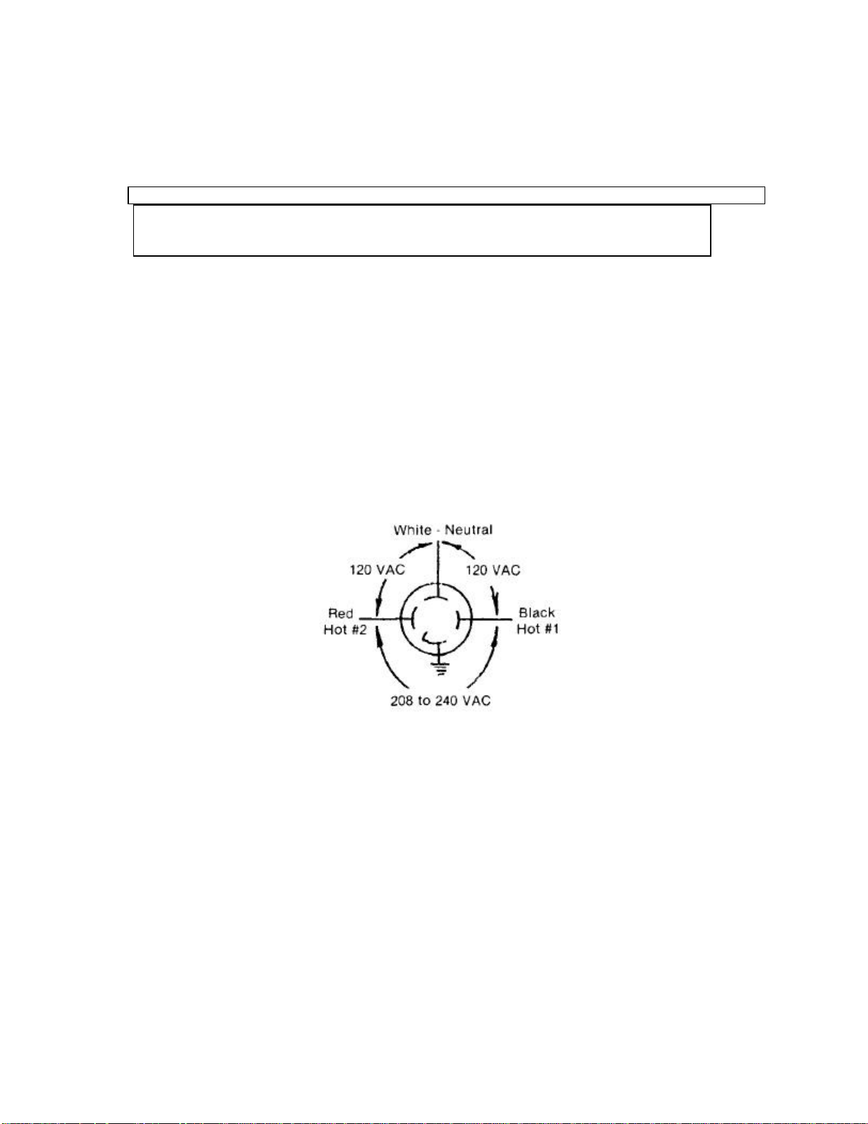
A. The power receptacle must be a 30 AMP, Single Phase, NEMA #L14-30 receptacle wired for 115/230
or 120/208 Volt to match the power requirements shown below.
B. Circuit Breakers in the control cabinet must be of 30 AMP rating.
Source Receptacle
NOW THE UNIT MAY BE SET IN PLACE.
1. Be Sure Tank Heater Switch is "Off."
2. Follow Plumber's Instructions.
3. Follow Electrician's Instructions.
YOU ARE NOW READY TO FILL THE TANK WITH WATER.
1. Follow initial operation instructions.
Page 4
Page 5
CONNECTING WATER SUPPLY LINE TO UNIT
WARNING:
DO NOT PLUG IN OR ENERGIZE THIS UNIT UNTIL INSTALLATION INSTRUCTIONS ARE READ AND
CAUTION: IF UNIT HAS BEEN CONNECTED TO
1. Flush water line before connecting to Brewer.
2. For less than 25' water run, use 1/4" line. For
3. A water shut-off valve must be installed on the
4. Water pressure should be at least 20 PSI and
UNDERSTOOD.
THE POWER SOURCE, UNPLUG IT
OR TURN OFF POWER AT
SOURCE.
Power to Brewer must be OFF before
proceeding with plumbing in stallation.
Brewer should be connected to COLD WATER
line.
more than 25' use 3/8" line.
incoming water line in a convenient location,
close to the unit.
flow at one gallon per minute.
NOTE: Unit must be installed on a water line with
pressure between 20 PSI and 90 PSI. If water
pressure varies greatly or does not fall into this
range, a pressure regulator should be installed.
NOTE: Line connections to machine must conform
to local codes.
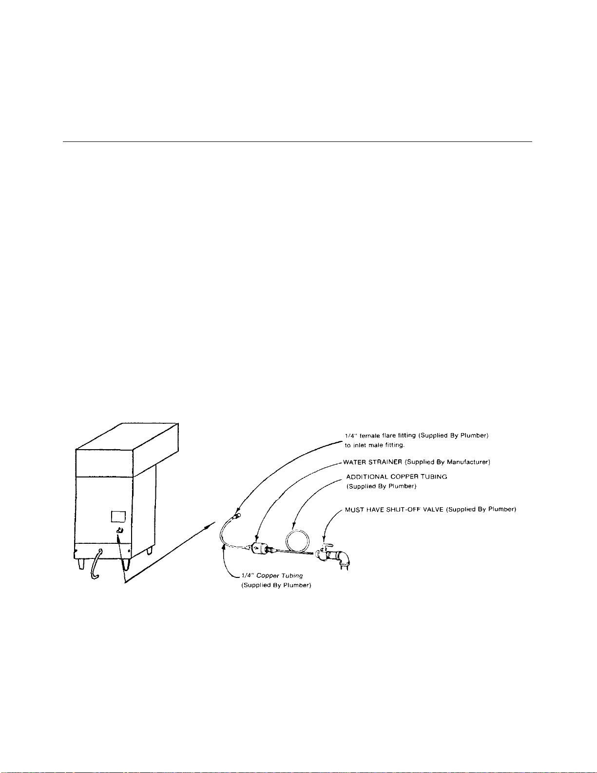
5. Connect the incoming water line coupler
assembly to the 1/4" male end of the water
strainer. Observe arrow direction for water
flow.
6. To delay build up of lime deposits in water tank,
we recommend the use of a Water Conditioner
such as Everpure QC7-MH.
Page 5
The National Sanitation Foundation requests a
provision be made in the incoming water line for
flexibility. This is necessary to allow tilting or moving
the machine for proper cleaning underneath, etc. A
tightly coiled length of copper tubing located on either
side of the water strainer would help comply with this
request.
Page 6
ELECTRICAL INSTALLATION
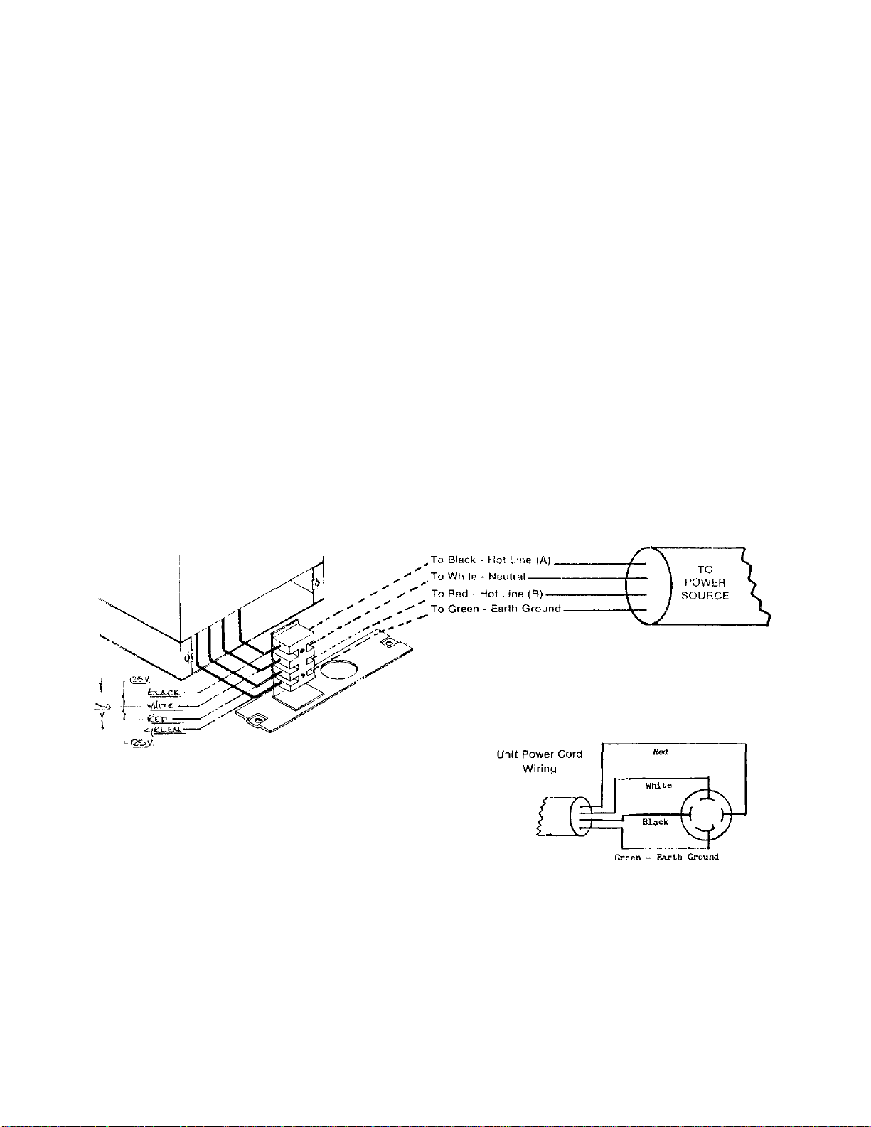
Electrical requirements: 115/230 (120/208) Volts
A.C. 50/60 hertz, 4 wire with ground, single phase,
30 amp wiring required.
Warranty is void if Brewer is connected to any
voltage other than specified above.
WARNING: Brewer must be properly grounded to
prevent possible shock haz ard. DO
NOT assume a plumbing line will
provide such a ground.
1. Energy Saver Tank Heater Switch on front of
Brewer must remain in OFF position until
plumbing is connected and Brewer is initially
filled with water. The switch must NOT be turned
on until after Step 6 is completed in the initial
operation instruction, See Page 7.
2. Electrical service line cord and NEMA
Plug and receptacle, or equivalent, must be
furnished by installer. Use copper wire on ly of
#10AWG wire size.
3. Plug power cord to power source.
4. After connecting service as specified, test the
voltages on the field wired side with a volt
meter. Do not turn on tank heater switch.
5. If plumbing connection has been made, the
Brewer is now ready for "Initial Operation
Instructions." If plumbing is to be done later, be
sure power is "OFF" and Brewer is not plugged
into outlet.
NOTE: Line connection to machine must conform to
local codes. See Diagram above.
Page 6
Page 7

INITIAL OPERATION INSTRUCTIONS
Electrician's and Plumber's Instructions should be
followed carefully before proceeding with Initial
Operating Instructions.
Be sure all electrical and plumbing connec tions are
tight.
1. Open water inlet valve.
2. Make sure Energy Saver Switch is in OFF
position.
3. Connect electricity.
4. Place empty Satellite in brewing position.
5. Place empty Brew Funnel into brew rails and
turn left or right so that handle is over receiving
Satellite.
NOTE: Handle must be turned all the way to left
or right so Micro Switch is engaged.
6. Press "Brew" Switch. Repeat a second time,
allowing five (5) minutes between cycles. Water
will begin to flow through brew funnel into
Satellite during third cycle.
7. Turn Energy Saver Switch to ON. On initial
warm up, some water may flow into the brew
funnel due to expansion of cold water in the
Tank.
8. Allow 20 minutes for initial water heat up. Time
will vary with incoming water temperature.
9. When correct brewing temperature is reached,
READY LIGHT will come on. Make sure
Satellite is empty. Press Brew Switch and run a
cycle of hot water only. At the end of
this cycle, Brewer will be ready for checking
timer adjustment.
10. Check a cycle of water ONLY to determine
water volume delivery. Appro ximately one (1)
inch down from the top of the Sight Glass
Assembly, on the shield, there are two (2) lines
stamped in the metal. The water should rise in
the Sight Glass, to a level between those lines
to be considered as a full delivery volume.
11. The Solid State Timer is pre-set at the fac tory to
run 146 seconds and allow 224 ounces of water
to flow into the Basin Pan. Timer adjustment is
located behind the 2 inch Plug Button in the
Front Panel in the upper left area. To adjust,
remove snap-in plug and turn dial clockwise to
increase timer cycle and water volume, or
counter-clockwise to decrease timer cycle and
water volume.
12. Replace snap-in plug.
13. The Thermostat is pre-set at the factory for
195°-205°. The Thermostat Adjustment is
located behind the Plug Button in the upper left
section of the Front Panel. To adjust, turn knob
clockwise to increase temperature, or counterclockwise to decrease temperature level of the
water in the tank.
14. Replace plug button.
15. Brewer is ready for use.
16 If water supplied to brewer is softened or
brewed coffee is too strong, see Adjustment
Tools and By -Pass Adjustment.
BREWING OF COFFEE
NOTE: To be sure water brewing temperature is
correct do not start a brewing cycle until
READY LITE is ON.
1. Slide brew chamber from the brew rails and
check to be sure wire rack (brew basket) is in
place in the brew chamber. Proper timing and
brewed coffee flow, through the brew chamber,
cannot occur without it.
2. Place one BLOOMFIELD filter paper into brew
chamber and add a pre -measured package
(standard package is 8. 0 ounces of grounds)
of URN GRIND coffee. Shake brew chamber to
level the filter paper and coffee bed.
3. Make sure satellite is empty before starting a
brewing cycle. Place empty Satellite in brewing
position and plug Satellite Cord into receptacle
inside of unit. Turn ON Satellite Heater Switch.
4. Slide brew chamber into brew rails and turn to
LEFT or RIGHT so micro-switch is engaged by
actuator tab on front of brew chamber.
5. Press BREW SWITCH - this action activates the
timer and water solenoid to automatically
complete a brew.
6. When the brew is finished and coffee flow has
stopped remove the brew chamber and discard
the used coffee grounds and filter paper.
Page 7
Page 8
PARTS IDENTIFICATION LIST
MODEL NO. 8702
REF.
PART NO. DESCRIPTION QTY. FUNCTION
NO.
1 8543- 52 #8 x 3/8 phillips head "B" screw. 2 Fastens top cover.
2 8706- 46 Top cover. 1 Covers basin body.
3 8706- 5 Outlet tube, to faucet. 1 Water faucet line.
4 8706- 4 Formed inlet tube ass'y. 1 Water faucet line.
5 8551- 30 1/4" male flare x 1/8"FPT. connector. 1 Connects water faucet line.
6 8514- 26 Needle valve. 1 Adjust water flow to faucet.
7 8706- 3 Inlet tube ass'y. 1 Water faucet line.
8 8706- 97 T fitting. 1 Connects water & cushion lines.
9 8706- 24 Straight tube. 1 Main water line connection.
10 8706- 1 Snubber tube assembly. 1 Water line cushion.
11 8706- 23 Snubber inlet tube. 1 Connects water.
12 SA-9052 Strainer. 1 Filters incoming water.
13 8702- 17 Outlet, snap -in. 2 Provides power to satellites.
14 8543- 52 #8 x 3/8 phillips "B" screw. 4 Accepts cover plate.
15 8706- 41 Cover plate, water tank body. 1 Access door.
16 8706- 13 Thermostat. 1 Controls water temperature.
17 9700- 377 Terminal block c ontact. 4 Protects wires.
18 7200- 6X #8-32 x 5/16" Ig. screw. 2 Attaches terminal block.
19 8700- 378 Terminal block end. 1 Protects wires.
20 8710- 10 #7/16-20 x 1/8" brass hex nut. 2 Secures water line.
21 8706- 156 Back cover sub -ass'y- 1 Access to electrics.
22 8942- 92 #8- 32 keps hex nut. 2 4
23 8700- 517 Relay, 120 v. 1 Transmit power.
24 18-126 #1/4-20 hex nut. 2 Fastens relay bracket & fastens locator bar.
25 8706- 166 Relay mounting bracket. 1 Accepts relay.
26 8705- 37 #8- 32 x 5/8" Ig. screw. 2 Accepts relay.
27 8706- 22 Locator bar. 1 Positions satellites.
28 8706- 64 #1/4-20 x 1" Ig. screw. 2 Fastens locator bar.
29 7200- 6X #8-32x5/16" Ig. screw. 4 Fastens basin body.
30 3543- 23 Tinnerman nut. 2 To accept top cover screw.
31 8941- 20 Adaptor fitting. 2 Connects water line for brewing.
32 8881- 8 Washer. 2 Accepts gasket.
33 8043- 30 Gasket. 3 Prevents leakage.
34 8873- 12 Male elbow 1/4" pipe x 1/4" male flare. 1 Connects water brewing line.
35 8706- 57 Basin pan sub-ass'y. 1 Holds water for brewing.
36 8706- 65 #6- 32 x 7/8" Ig. screw. 4 Holds micro switch.
37 8706- 19 Switch, micro. 2 Insures brew funnel placement.
Fastens relay & fuse holder to body. Fastens basin
Page 8
Page 9

REF.
PART NO. DESCRIPTION
NO.
38A 8875-68 Fuse holder 1 Holds fuse.
38B 8875-C9 Fuse—15 Amp. 1 Electric line protection.
39 8861-16 #6-32 Keps hex nut. 4 To accept a screw.
40 8704-5 Basin sub -assembly. 1 Houses components.
41 8706-186 Pilot tight assembly. 1 Shows water is ready for brewing.
42 8551-100C Hex lock nut. 1 To accept faucet.
43 8551-100B 7/16" External tooth lock washer. 1 To accept faucet.
44 8551-100A Washer. 1 To accept faucet.
45 8706-169 Faucet assembly. 1 Dispenses hot water.
45A 8706-169A Faucet spout ass'y. 1 Connects to faucet.
46 8706-28 Switch, brew. 2 Starts brew cycle.
47 8707-34 Switch, 120 v. 1 Energizes tank heater.
48 8706-17 Timer, includes knob, faceplate & screws. 1 Controls coffee timing.
49 3-100 #6-32 x 1/4" Ig. screw. 2 Holds thermostat.
50 8706-96 Thermostat knob. 1 Adjust thermostat.
51 8706-21 Water inlet tube. 1 Water line for brewing.
52 8706-76 Plug button 1- 1/8". 1 Access to thermostat adjustment.
53 8706-75 Plug button 2". 1 Access to timer adjustment.
54 8700-591 Leg. 4 Elevates unit.
55 8541-48a Elbow. 1 Water line for brewing.
56 8551-35 "T" coil inlet fitting. 1 Transfers water.
57 8706-102 Reducer, adapter. 1 Path of water.
58 8541-120 Solenoid valve 120 v. 1 Turns water on & off, flow control.
58A 8541. 122 Screw, 10 -32 x 1/2" Pn. Hd. 2 Secures solenoid valve.
59 8706-9 Wire rack, brew chamber. 1 Holds filter paper.
60A 8706-107 Brew funnel, cup only. 1 Holds coffee grounds, and directs brew to satellite tank.
60S 8706-60 Brew funnel complete with wire rack & handle. 1 Promotes brewing.
61 8707. 3 Screw. 1 Fastens handle to brew funnel.
62 8707-2 Handle, brew funnel. 1 Lifting and turning brew funnel.
63 8706-54 Front cover sub-assembly. 1 Covers internal components.
64 18- 302 #8-32 hex cap nut. 2 Accepts hold strap.
65 8043-47 #10- 32 x 1 " Ig. screw. 1 Seals tank cover.
66 8043-5 Hold down strap. 1 Holds tank cover on.
67 8512-41 Seal washer. 3 Seals thermostat, water coil.
68 8043-28 1/2-20 hex nut. 2 Fastens heating element.
69 8514-68 Tank cover sub-assembly. 1 Seals tank.
70 8043-12 Tank cover gasket. 1 Seals cover to hot water tank.
71 8706-8 Hot water coil assembly. 1 Transports water.
72 8535-2 Heating element 5500 w., 230 v. 1 Heats water.
73 8706-20 Vent tube. 1 Air Vent.
74 8706-6 Inlet elbow. 1 Water tine from tank to pan.
QTY. FUNCTION
Page 9
Page 10
REF.
ACCESSORY AND IT
EMS NOT SHOWN
8702-18
Label, for 65 Watt Outlet
NO.
75 8043-83 Hi-limit thermostat. 1 Prevents over heating.
76 8043-11 Outlet elbow. 1 Water line from tank to sprayer disc.
77 8706-25 "T" by-pass flow tube. 1 Path of water.
78 8706-188 Tubing connector. 1 Path of water.
79 8942-33 Gasket. 2 Seals water coil.
80 8551-53 7/16" I. D. x 3/4" O. D. 2 Seals water coil.
81 8706-111 Nylon screw (by -pass). 1 Adjust water flow.
82 8706-26 By-pass valve body. 1 Path of by-pass water.
83 8043-13 Spray elbow. 1 Water outlet to sprayer disc.
84 8543-42 Spray head gasket. 1 Seals sprayer disc.
85 8543-44 Sprayer disc. 1 Control spray pattern into coffee.
86 8543-74 #4-40 hex nut. 1 Accepts screw.
87 8543-73 #4-40 x 1-1/2" Ig. screw. 1 Fastens water tube-
88 8706-68 Water inlet tube. 1 Deposits cold water at bottom of hot water tank.
89 8706-49 Water tank assembly. 1 Holds water.
90 6541-39 #1/4-20 x 3/4" Ig. screw. 2 Fastens front cover panel to body.
91 8543-69 Heyco bushing. 3 Protects wires.
PART NO. DESCRIPTION QTY. FUNCTION
8704-1
8704-2
8704-3
8705-44
8706-205
8706-110
Label, Front
Label, Front Right Side
Label, Front Left Side
Faucet Shield
By-Pass Set Kit
Filter Papers -Box of 500.
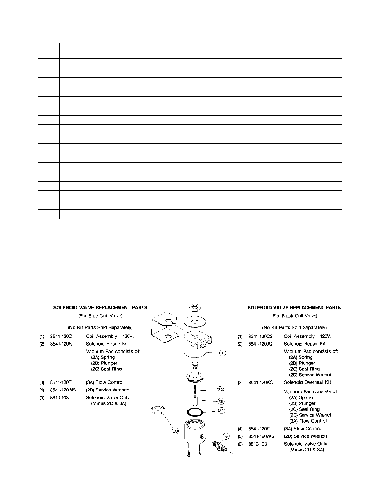
REF. #58 COLD WATER ENTRANCE SOLENOID VALVE PART NO. 8541 -120
(Consists of Valve and Flow Control)
Page 10
Page 11

EXPLODED VIEW
MODEL NO. 8702
Page 11
Page 12

REPLACEMENT PARTS LIST
MODEL NO. 8703 SATELLITE
Page 12
Page 13

REPLACEMENT PARTS LIST
2. 8705-21 Satellite Cover Only
3.
8705-4 Handle
-
Rod 4. D20002
-
3 Screw, 10
-
32 5. 8942-92 Hex Nut,
8-32, Keps
6. 8705-37 Screw, 8
-
32 x 5/8
7.
8705-6 Locating Block
8.
8705-7 Locating Block Seal
9.
8705-1 Spacer, Tank Cover Retainer
10. 8705-5 Retainer Spring
12. 35-110 Cord Grip
—
Strain Relief
13. 8596-43 On/Of
f Lighted Switch
14. 8703-8 Satellite Body S/A
15. 8703-3 Heat Sink Plate
17. 8703-26 Retainer
18. 8705-60 Spacer Tube
19. 8703-27 Access Door
20. 8705-45 Foot 21. 8706-64 Screw, 1/4
-
20 x 1 22. 8705-40 Drip Tra
y Cover
23. 8705-41 Drip Tray Body
24. 8705-22 Satellite Tank Assembly
25. 8705-26 Seal Drain Fitting
26. 8705-33 0 Ring
—
Tank Top Seal
27. 18-126 Hex Nut
-
1/4-20
8706-110 Box of 500 Filter Papers
8706-205 By-Pass Set Kit
2. 8700-25J Upper Washer
for Sight Glass 1/8" Standard
8700-25K Upper Washer for Sight Glass 1/16' Special
3.
8600-20 Shield
-
10" x 3/4" O.
D. - Aluminum
4.
8705-11C Sight Glass
-
10 x 5/8 O.
D. - Polysulpnone
5.
8705-11B Lower Sight Glass Washer
-
w/ 1/16" Hole
8700-25H Lower Sight Glass Washer
-
w/5/16" Hole
6.
8705-11G Shield Base
7.
8705-11D Shank Assembly w/Wing Nut
8.
9.
8705-11L Upper Assembly
—
Black Bonnet
10. 8700-25L Seat Cup
11. 8705-11K Washer for Clean Out C
ap 12. 8705-11J Clean Out Cap with Washer
MODEL NO. 8703 SATELLITE
REF. NO. PART NO.
1. 8705- 18 Cap Sub-Assembly
DESCRIPTION
11.
16.
28. 8705- 11 Faucet and Sightglass Assembly
8703- 11
8703- 25
8705- 44 Faucet Shield
Cord and Cap Assembly
Heating Element, 60 Watt
ACCESSORY AND ITEMS NOT SHOWN
REPLACEMENT PARTS LIST
FOR FAUCET ASSEMBLY ONLY - PART NO. 8705-11
REFERENCE NO. 28 ABOVE
REF. NO. PART NO. DESCRIPTION
1.
8600-17
Shield Cap
8705-11F
Faucet only w/o Shank & Sight Glass
Page 13
Page 14

HOT WATER FAUCET
PART
Page
14
REPLACEMENT PARTS LIST
REF. NO. PART NO. DESCRIPTION
1. 8551-275 Repair Kit (sold as Kit only)
A.
B.
C. " Valve Disc
D. Kit "0" Ring - #6, #7 & #8
E. Contains Tee Nut
F. J L
G.
H.
A. 8706. 1698 Faucet Handle, Red
2. 8551. 275B Stream Straightener
3. 8551. 100A Washer Rubber
4. 8551. 100B 7/16 External Tooth Lock
5. 8551. 100C Hex Lock Nut
SEALS AVAILABLE
6. 8551-200B "0" Ring Stem Seal 5/16" O. D
7. 8551-200A "0" Ring Seal 1/4" O. D.
8. 8551-200C "0" Ring Spout Seal 3/8" O. D.
C. 8551. 275A Valve Disc
TOOL AVAILABLE
9. 8551. 200E Adaptor Tool - Service
10. 8706-169A Flexible Spout
Handle (Color -Red)
Valve —Stem
Spring
Guide
Bushing
Insulation Card (Not Shown)
(Not Shown)
Washer
Wrench
WATER FLOW DIAGRAM
Sequence of Operations:
WATER FLOW FOR BREWING OPERATION
1. Pushing brew Start Switch energizes the Timer. The Timer
then energizes the Solenoid Valve, allowing water to flow
into the Basin Pan and then into the Hot Water Tank. The
length of time the Solenoid Valve is energized is controlled
by the Timer setting.
2. The water entering the Hot Water Tank from the Basin Pan,
flows to the bottom of the Tank through the Water Inlet
Tube.
3. The addition of water into the bottom of the Hot Water Tank
causes the hot water at the top of the Tank to flow out
through the Outlet Elbow of the Tank Cover, to the Spray
Head.
(Both Brewing Sections)
PART II
Sequence of Operations:
WATER FLOW FOR FAUCET OPERATION
(Faucet Section O niy)
1. The incoming cold water supply connects to a "T" Inlet
Fitting on the Unit. Water flows from the "T" Inlet
Fitting through the Inlet Tube, Needle Valve and
Formed Inlet Tube into the input connection of the
Water Coil.
2. The Water Coil is submerged in the Hot Water Tank
and draws heat from the surrounding hot water.
Water flowing into the Water Coil is then heated and
flows out through the Formed Outlet Tube to the
Faucet. (The water flowing through the Water Coil,
which feeds the Faucet is not controlled by the
Solenoid Valve. This portion of the system is always
under pressure and is con trolled by the Faucet.
Opening the Faucet allows the water to flow through
the Water Coil system.)
3. The Needle Valve, in the system, controls the
volume of flow from the Faucet and is adjusted to
allow a gentle stream of water to be dispensed
through the Faucet, without splashing into the
cup. (The Faucet is intended as a cup to cup hot
water supply.)
NOTE: Drawing hot water from the Faucet,
during a Brewing Cycle DOES NOT affect the
volume of the finished brew.
Page 15

EQUIPMENT SET-UP AND CLOSE PROCEDURES
Daily Start Up Procedure
3. Rinse brew funnel and satellites thoroughly.
1. Turn tank heater switch ON.
2. Wait for "Ready to Brew" light to come on.
(Approximately 10 minutes.)
3. Brewer is now ready for use.
Daily Close Down Procedures
1. Turn tank heater swit ch OFF.
2. Pour out any left over coffee in satellites and
clean inside of satellites and brew fun nel
with a solution of Sanitizer.
Do Not Immerse Satellite in Water.
TROUBLESHOOTING
It is very imp ortant when servicing equipment to:
1. Define the basic Problem.
4. Wash spray disc in sanitizer solution; rinse
thoroughly, and replace.
5. Use a damp cloth and clean the entire brew head
area to remove any accumulated coffee
residue.
NOTE: DO NOT USE ABRASIVE CLEANERS THAT
MAY DAMAGE THE EXTERIOR FINISH OF THE
BREWER.
Should the problem remain after exhausting the
troubleshooting steps suggested, refer to the
Order/Service Information section of this Manual.
2. Isolate the Probable Cause.
3. Take Corrective Action, regarding those items
hampering proper operation of the equipment.
It is usually relatively easy to define the basic
problem, but sometimes very difficult to pin point the
precise cause.
A Trouble-shooting Guide is provided in this
Manual to suggest probable causes and corrective
actions for each. Obviously, if the cause is not
isolated and corrected, proper operation of the
equipment cannot be restored.
Warning: Inspection, testing and repair of electrical
equipment should be performed only by qualified
service personnel. The brewer should be
unplugged when servicing, except when electrical
tests are required.
Danger: Use extreme care during electric circuit
tests. Live circuits will be exposed.
Page 15
Page 16

PROBLEM
clean screen filter or replace
A. No water from the Spray Disc.
(Brew Switch is activated.)
TROUBLE SHOOTING GUIDE
PROBABLE CAUSE
A. 1. No Water
A. 2. No Power Check line fuse or circuit breaker. If OFF, turn ON, or replace fuse.
A. 3. Loose Wire or Connection Remove unit top cover and Body Column Front Cover.
A. 4. Screen Filter and QC7-MH Screen filter or QC7-MH may be plugged—
A. 5. Start Switch
A. 6. Timer
A. 7. Solenoid Valve Check Solenoid Valve for continuity at the terminals of the Solenoid
CORRECTIVE ACTION
Push brew funnel totally to the left or right to activate the micro-switch.
Be sure water shut-off valves are open. Check continuity of microswitch, if switch does not make and break contact, replace microswitch. See micro-switch replacement, non -scheduled maintenance.
Make certain unit is alone on its own electrical lines.
If fuses or circuit breaker continue to "open," call Qualified
Serviceman.
Check all wires and connections, be certain none are loose or
disconnected.
Repair loose connections, and/or wires and reattach.
QC7-MH.
Check switch continuity. If switch does not make and break contact,
replace Start Switch. See Start Switch replacement — non-scheduled
maintenance.
When start button is pressed, the timer should acti vate. The timer
should continue to operate until the cycle is completed. If it does not,
replace the timer.
Valve Coil. If no continuity, replace either the Solenoid Coil or the
Complete Solenoid Valve.
B. Too much water or too little
water, satellite short or
overflows.
A. 8. Water Supply Tubing (from
Solenoid to Basin.)
B. 1. QC7 Filter is clogged.
B. 2. Timer needs adjustment. Turn Timer Adjustment clockwise to increase the water or
B. 3. Flow Restrictor in output end of
Water Solenoid Valve (dirty, missing,
damaged or inoperative)
Check for twist or "kink" in water supply tubing, blocking water flow into
basin pan.
Replace QC7 cartridge.
counterclockwise to reduce the water.
Clean or replace flow restricter or replace the Water Solenoid Valve.
Clean or replace the flow Restrictor or the complete solenoid.
Page 16
Check timer cycle several times with a stopwatch. If times are
irregular replace the timer.
Particles in the water solenoid valve may partially clog the orifice of
the flow restrictor.
Page 17

PROBLEM PROBABLE CAUSE CORRECTIVE ACTION
B. Too much water or B. 4. All Automatic Brewers require a constant water pres
too little water, Water Pressure sure between 20 PSI and 85 PSI for consistent, troublesatellite short or Variations free operation.
overflows.
(Continued) (Water pressure rises Wide swinging water pressures lead to erratic delivery.
above 85 PSI or falls A pressure regulator may be needed to stabilize high
below 20 PSI) running pressures.
A water source that falls below 20 PSI may result in
short pots or erratic volume delivery.
C. Water keeps run C. 1. Check and clean inside of the water solenoid valve,
ning into Fill Basin. Water Solenoid Valve and plunger.
(Will not shut off (Plunger stuck open)
with Power Plug
pulled.)
Check inside surface of water solenoid port, if it is
scored, chipped or damaged, replace the water sole
noid valve.
(Shuts off when C. 1A. Check with switch continuity, replace if defective.
Power Plug is Start Switch
pulled.)
C. 2A. Timer is defective, will not cycle to "OFF" condition.
Timer Replace timer.
D. Water fails to heat D.. 1 Check if power cord is plugged into wall outlet.
and brewer does No Power to Unit
not work.
(Water from the
faucet is cold.)
Check line fuse or circuit breaker— if off, turn it on or
replace.
If circuit continues to be open, call a Qualified Service
man.
Defective cord or plug —repair or replace.
Loose wires—remove front and top panels and check
for loose connections, screws or terminals. Tighten
screws, repair or replace terminals.
E. Water fails to heat, Unit has power, the
but brewer does failure is due to:
operate. E. 1. Switch in off position—turn on.
Heater Switch Defective switch, replace switch.
(Water from the
faucet is cold.) E. 2. Check for loose wire or connection. Repair or
Tank Heater reconnect.
Check for proper voltage at Tank Heater Terminals.
If voltage is present, element is defective, replace ele
ment.
E. 3. Check for a loose wire or connection. Repair and/or
High Limit Safety Control reconnect.
Disconnect wires and check for continuity on both ter
minals of the High Limit Safety Control.
If continuity is present, the control is functioning prop
erly, if not, replace Hi limit.
E. 4. Check for loose wire or connection feeding into Ther-
Thermostat stat.
If READY light is ON turn the thermostat adjusting
(READY Light ON is a shaft clockwise to the full ON position.
guide.) If READY light goes out, water should begin to heat-
adjust to proper water temperature.
If READY light stays ON, replace the Thermostat.
Page 17
Page 18

PROBLEM PROBABLE CAUSE CORRECTIVE ACTION
voltage condition exits, an electrician should be consulted. A low voltage
F. READY light fails to glow
when water reaches brew
temperature.
F. 1. READY light is defective. If thermostat cycles on and off and READY Iight does not glow, replace
READY light.
G. Water heats, but is not hot
enough.
H. Water heats, but longer than
12 minutes. (Slow recover)
I. Water temperature too hot.
ALSO CALLED: • STEAMING •
BOILING • HEAT NEVER
SHUTS OFF
G. 1. Thermostat adjustment. If water from the water outlet tube (with spray disc re-
moved) is less than 195°F., and thermostat cycles the Tank Heater OFF,
adjust the Thermostat to a higher setting. 1/4 turn equate approximately
18°F (10°C) temperature change. To increase the tank temperature, turn
the adjustment shaft in a clockwise direction.
G. 2. Thermostat defective. If adjusting Thermostat to a higher setting does not correct the problem,
G. 3. High Limit Safety Control
(READY light does not come on.)
H. 1. High Lime Deposits Delime unit.
H. 2. Low voltage at source. Check voltage. 11 should be within 110% of unit rating plate, if a tow
H-3. Low voltage at Tank Heater. Voltage Rating and Power Source must be the same. Cneck wiring
1. 1. Thermostat Thermostat out of calibration or defective. Adjust or replace. it.
the thermostat is defective, replace it.
High Limit Safety Control is defective. Replace it.
condition. can and does cause frequent service calls, as well as extending water heating time.
diagram and name plate.
J. Dry coffee remain ing in the
brew fun nel after a brew has
been completed.
K. Coffee Grounds do not get
wet — water stays in the basin.
Coffee Grounds do not get wet
— water leaks out of the bottom
of the unit.
J. I. Spray Disc missing The Spray Disc must be in place to break up the water stream.
J-2. Filter Paper Use
J. 3. Improper loading of the Brew
funnel.
K. 1. No syphon action. Check elbow connection from basin to tank, it may be twisted and not
K. 2. Leak in Water Path from basin
to final outlet.
Filter should be centered in the brew funnel and the coffee bed should
toe! level.
open to water flow.
Check for correct fit and at: A. Elbow from. basin to tank cover. B. Tank
Cover Gasket. C. Output eitelbowand tube assembly.
Page 18
Page 19

PROBLEM PROBABLE CAUSE CORRECTIVE ACTION
L. Weak Coffee
L. 1. Too much water. Verify water level on sight glass. Adjust timer if necessary.
L. 2. Water temperature too low. Adjust thermostat to a higher setting.
M. Strong Coffee
N. Brew Time exceeds 8
minutes for full satellite.
L. 3. Improper loading of brew
funnel.
L. 4. Not enough coffee in brew
funnel.
M. 1. Not enough water. Verify water level on sight glass. Adjust timer if necessary.
M. 2. Too much coffee in brew
funnel.
M. 3. Two (2) Filter Papers or
improper filter paper used.
M. 4. Coffee being drawn d uring a
brew cycle.
M. S. By- Pass Valve improperly set
or unit connected to softened water
source.
N. 1. Water Supply has been
softened.
Filter paper must be centered in brew funnel. Coffee bed must be level
when starting a brew cycle.
Verify package weight.
Verify package weight.
Use only one (1) recommended Filter Paper. Improper Filter Paper can
restrict water flow.
At beginning of a brew cycle coffee is very strong, you must wait until
cycle is completed before drawing to serve.
Insufficient water being by-passed or unit is brewing with softened
water—see adjustment section of manual.
Brewer was shipped with soft water valve set of 25%. If soft water
conditions exist valve must be opened slightly. See Non- Scheduled
Maintenance.
N. 2. Use of two (2) Filter Papers or
improper Paper Filters.
Use only one (1) recommended Filter Paper. Two (2) Paper Filters or the
use of foreign papers can cause brew chamber run-over.
Page 19
Page 20

PROBLEM PROBABLE CAUSE CORRECTIVE ACTION
0. 1. Incoming water source shut- off. Check and turn ON the water source valves. 0. No Water from water faucet.
0. 2. "T" Valve (Between Water
Solenoid and water tank.)
P. Faucet keeps dripping. P. 1. Foreign matter inside the
valve, holding the valve seat from
closing completely.
Q. Overflowing Satellite. Q. 1. Receiving Satellite not empty
when a b rew cycle is started.
R. Satellite does not keep coffee
hot.
R. 1. Not plugged into power source. Plug Power Cord into electric source.
R. 2. Switch not turned on. Turn on Satellite Power Switch.
The "T" Valve must be open to permit water flow from the faucet.
It may be partially closed to control the force of the water stream
from the faucet.
Shut off water, disassemble and clean the faucet seat. If faucet still leaks
or drips, install a complete repair kit (part #8551-275). If faucet continues
to drip, the seat has been damaged, replace the faucet assembly.
Always start with an empty receiving Satellite when a brew is started.
R. 3. Switch defective. Check switch, if it does not make and break continuity change switch.
R. 4. Loose or disconnected wire. Reconnect loose wire or replace loose connector.
R. 5. Heating element electrically
"open."
Check heating element for continuity. If "open" replace element.
Page 20
Page 21

PROBLEM PROBABLE CAUSE CORRECTIVE ACTION
when making level adjustments. Level the unit from left to right and front
S. Satellite Faucet keeps
dripping. (Dripping and/or bitter
taste.)
S. 1. Seat cup clogged with residue. The faucet seat cup should be removed and freed of all coffee oils and
residue. It must seat properly on the faucet opening. The seat cup
should be kept clean to prevent build-up of oils that may turn rancid and
result in bitter taste to the coffee.
T. Water drips from basin head
unit.
T. 1. Unit not level. Level the unit. For proper unit operation, it is very im portant that the unit
be level when it is standing in its proper operating position. A spirit level
should be placed on the top plate of the unit, at the edge, as a guide
to back by turning the ad justable feet that support the unit.
Page 22

SERVICE INSTRUCTIONS DETAILED ILLUSTRATIONS
MODEL 8702 SATELLITE COFFEE BREWER
NON. SCHEDULED MAINTENANCE
Under normal conditions and with proper use and
care, very little non-scheduled maintenance will be
required for this coffee brewer. However, this
section provides procedures for removal and
replacement of various major components used in
the brewer in the event that servicing becomes
necessary. Before replacing any component, refer
to the Trouble -shooting Section for assistance in
determining the cause of any problem and to verify
that removal is required.
Recommended Tools
1-Flat Head 1/4" Blade Screwdriver
1—Phillips Head Screwdriver
1 —9" Adjustable Wrench
1 —6" Adjustable Wrench
1—Thermometer/Digital Pyrometer
1 —Voltmeter
1 —Continuity Tester
Component Access
All components are accessible by the removal of
two (2) panels. The top panel provides access to
the Tank Lid Assembly which includes the Heating
Element and Water Coil; Tank Body, Switches,
Ready to Brew Light, Faucet and Needle Valve
(#6).
The front panel provides access to the Solid State
Timer and the Solenoid Valve.
The screen filter/strainer (#12), is located in the
rear, outside the brewer.
CAUTION: Always disconnect brewer electric
sources before servicing.
To remove front panel for service, remove two (2)
screws located under front of brewer.
To remove top plate for service, remove two (2)
screws and lift up.
Thermostat Replacement
WARNING: Turn off Tank Heater Switch and un-
plug the brewer before removal of any panel or
replacement of any component.
1. Remove front panel and top cover.
2. Loosen the two (2) screws (#49) fastening the
thermostat body to the bracket.
3. Remove wires to thermostat (#16).
4. Remove the thermostat bulb by loosening hold
down nut and pull up firmly.
5. Lift thermostat and probe from brewer.
6. Install new thermostat in reverse order, steps 2-
5.
Page 22
Page 23

7. Place empty brew funnel into the funnel rails
and place an empty satellite in position.
3. Disconnect wires from all fittings on Tank Lid
(#69).
8. Plug in brewer.
9. Press Brew Switch. If Tank is full of water, the
water will flow from the spray disc through the
funnel and into the satellite. If the tank is not full
it may be necessary to repeat this operation
one more time to fill the Tank with water.
10. Turn on Tank Heater Switch.
11. Check temperature calibration.
12. When thermostat is calibrated, unplug brewer
and replace top cover panel and front panel.
(49) (16)
Heating Element Replacement
4. Lift out Tan k Lid with all components attached.
5. Remove two (2) hex nuts securing Heating
Element to Tank Lid and remove Element.
6. Install new Heating Element to Tank Lid.
7. Return Tank Lid Assembly to tank and re connect,
reversing steps 1 - 4.
8. Place empty brew funnel into the funnel rails and
set an empty satellite in place.
9. Plug in brewer and turn on water.
10. Press Brew Switch. If Tank is full of water, the
water will flow from the spray disc through the
funnel and into the satellite. If the tank is not full
it may be necessary to repeat this operation one
more time to fill the Tank with water.
11. When the water flow from the funnel stops,
unplug brewer and replace top cover.
12. Turn on Tank Heater Switch.
WARNING: Turn off the water and the Tank Heater
Switch and unplug brewer before removal of any
panel or replacement of any com ponent.
1. Remove the two (2) screws in the rear cor ners
of the top panel. Slide panel back and up to
remove.
2. Remove Thermostat (#16) Seal Nut, located on
tank cover and gently lift out the thermostat
sensing tube and bulb from the fitting.
Disconnect Outlet Tube (#77) from Outlet Elbow
(#76). Remove Inlet Elbow (#74) and Vent Tube
(#73) from Water Basin Pan (#35). Lift basin
pan from brewer. Unscrew Hold Down Strap
(#66) and slide free. Disconnect Water Lines
(#3 and #4) at flare fittings on tank lid.
Timer Replacement
WARNING: Turn off Tank Heater Switch and unplug
the brewer before removal of any panel or
replacement of any component.
1. Remove two (2) Front Panel Mounting Screws.
2. Remove Front Panel.
3. Remove all wires connected to Timer (#48
4. Unscrew Timer from the Mounting Bracket.
Page 23
Page 24

5. Remove Timer from the brewer.
6. Fasten new timer to the Mounting Bracket.
7. Reinstall wires to Brew Solenoid Valve and
Wiring Harness (follow color codes).
8. Reinstall Front Panel, reversing steps 1-2.
9. Plug in Brewer and turn on Heater Switch.
10. Check and adjust water volume.
Solenoid Valve/Flow Restrictor Replacement
WARNING: Turn off the Tank Heater Switch and
unplug Brewer before removal of any panel or
replacement of any component.
1. Shut off water supply to the Brewer.
2. Remove two (2) Front Panel Mounting Screws.
3. Remove Front Panel.
4. Remove the wires to the Solenoid Valve (#58).
5. Remove the Hex Nut at the outside rear in let
port.
6. Remove flare fitting from the tee inlet.
7. Remove Solenoid from brewer.
To replace Flow Restrictor:
1. Use two (2) wrenches, remove Outlet Fit tings
from outlet side of Solenoid Valve. Restrictor
is located inside the 5/8" fitting. Replace the
complete Restrictor Fit ting Assembly.
2. Replace Restrictor into Outlet Elbow, use
pipe thread tape around threads to pre vent
leaks.
Hi-Limit Safety Control Replacement
WARNING: Turn off T ank Heater Switch and un-
plug the brewer before removal of any panel or
replacement of any component.
1. Remove two (2) screws and top cover.
2. Remove the wires from the Hi-Limit Safety
Control (#75).
3. Lift the Retaining Spring to remove the Hi-Limit
Safety Control.
4. Replace the new Hi -Limit Safety Control by
sliding it into place under the Retaining Spring.
5. Reinstall the two wires to the Hi -Limit Safety
Control.
6. Make sure that Hi-Limit Safety Control is
securely mounted and that all electrical
connections are tight.
7. Plug in Brewer and turn on Tank Heater Switch.
3. Replace the Assembly into the Solenoid after
wrapping the threads with pipe tape. Do not
use liquid or paste pipe seals, as they tend to
creep into the Sole noid and will result in
improper opera tion.
8. Install new Solenoid, reversing order of Steps 1-
6.
9. Plug in Brewer and turn on Tank heater Switch.
Page 24
Page 25

Switches and "Ready to Brew" Light
Page 25
WARNING: Turn off the Tank Heater Switch and
unplug brewer before removal of any panel or
replacement of any component.
Whenever switch replacement becomes necessary,
proceed as follows:
1. Remove two screws from top cover.
2. Lift off cover.
3. Lift Water Basin to reveal switches and lights.
4. The switches (#47, #46) and the "Ready to
Brew" Light (#41) are removable through the
front of the Brewer. Compress the spring clip
located on the inside of the Brewer and push
forward.
5. Remove wires from the old switch and con nect
them to the new switch or light. Follow color
code on wire to color code on switch or light.
6. Re-insert switches and replace top reversing
steps 1-4.
7. Plug Brewer into electric outlet.
4. Remove wires from defective switch.
5. Remove screws holding switch in place.
6. Replace Micro-Switch reversing Steps 1-5.
7. Plug Brewer into electric outlet and turn on Tank
Heater Swi tch.
HEATED SATELLITE Service and
Part Replacement
Micro-Switch Replacement
WARNING: Turn off the Tank Heater Switch and
unplug brewer before removal of panel or
replacement of any component.
Whenever Micro -Switch replacement becomes
necessary, proceed as follows:
1. Remove two screws from top cover.
2. Lift off cover.
3. Lift Water Basin to reveal Micro-Switches (#37).
WARNING: Prior to doing any service work on a
heated Satellite be sure the Satellite is completely
empty of fluid and to disconnect the Satellite Power
Cord from the power source receptacle.
1. Turn the Satellite to a position where the
bottom access plate can be removed. See
exploded view of the Satellite.
A. Turn each of the four (4) feet (#20) counter -
clockwise until loose and set them aside.
B. Remove the large slotted head screw (#21)
located in the center of the bottom access
plate (#19) and remove the access plate.
2. The heating element (#16) and the power cord
(#11) may be tested and/or replaced through
this access opening without disassembling the
unit any further.
3. The On/Off power switch (#13) also can be
tested for make and break of continuity, when
the switch is activated to each position. If it
does not make and break the circuit, replace it.
A. The switch may be removed through the front
of the cabinet by depressing the plastic clips
on the switch from inside the cabinet and
pushing the switch out the front.
Page 26

B. Remove the wires from the original switch
and place them in the same position on the
replacement switch.
C. Depress the plastic mounting clips on the
switch and push the switch wires through and
into position in the cabinet hole.
4. The Satellite Reservoir Tank (#24) may be
removed or replaced, in the following order.
A. Remove the faucet assembly (#28) from the
Satellite.
B. Remove the bottom access plate (#19) see
step #1 above.
C. Disconnect wire connections at the heater
element (#16) terminals.
D. Lift the reservoir tank (#24) out of the top of
the Satellite Body.
E. Reassemble in reverse order—steps 4D
through 4A.
NOTE: The faucet assembly periodically MUST be
disassembled and thoroughly cleaned of coffee oil
and residues. If this is not done com -plaints of
strong, bitter coffee may result.
To properly clean the faucet use a solution of urn
cleaner and a brush.
1. Remove sight tube cap (#1) and lift out the
polysulphone sight tube. Use care not to lose
the lower sight tube washer (#5) if it comes out
with the tube.
2. Remove the lower sight washer (#5).
3. Unscrew the faucet bonnet assembly (#19) and
lift it from the faucet body.
4. Remove the seat cup (#10) from the faucet
bonnet assembly (#9).
5. Remove the clean out cap (#12).
6. Clean all par ts with an urn cleaner solution
including the inside of the satellite reservoir
tank and rinse thoroughly.
7. Reassemble in reverse order—steps 5 through
1.
To Delime Brewer:
WARNING: Turn off the Tank Heater Switch and
unplug brewer before removal of any panel or
replacement of any component.
1. Shut off water to brewer.
2. Remove two (2) screws and top cover.
3. Remove Water Basin.
4. Remove all wires to Tank Lid.
5. Remove all water connections to Tank Lid.
6. Remove hold down strap and lift out Tank Cover
which has heating element, inlet tube and hot
water faucet coil attached.
7. Remove approximately 1 gallon (1/4) of water
from tank and replace with Deliming Agent such
as "Lime Away."
8. Replace Tank Lid Assembly and parts and let
stand for one hour. (It is not necessary to fasten
in place.)
9. Remove Tank Lid Assembly and syphon all
liquid from tank.
10. Reassemble entire unit and connect all
plumbing and electrical connections.
11. Plug in Brewer and turn on water.
NOTE: Heater Switch must be OFF.
12. Place empty Satellite in brewing position.
13. Place empty Brew Funnel in brewing position
over empty Satellite.
14. Press "Brew" Switch. Repeat a second time,
allowing five (5) minutes between cycles. Water
will begin to flow through brew funnel into
Satellite during third cycle.
15. Turn Energy Saver Switch to ON. On initial
warm up, some water may flow into the brew
funnel due to expansion of cold water in the
Tank.
16. Allow 20 minutes for initial water heat up. Time
will vary with incoming water temperature.
17. Run at least 4 cycles of water only before
brewing coffee.
NOTE: The outside stainless steel surface of the
Satellite can be cleaned with urn solution on a
sponge, rinsed clean and wiped dry to maintain its
original stainless beauty.
Do not use abrasive cleaners to polish the outer
Satellite surfaces as they may scratch and mar the
surface.
Page 26
Page 27

IMPORTANT ADJUSTMENT TOOLS
(Do Not Discard Them)
Supplied with this Model#8702 Coffee Brewing
Unit are:
1. Part #8706-200, By -Pass Test Hose Assembly
(used for checking the By -Pass Water volume).
2. Part #8706-202, Flow Set Gauges (used for
setting the By -Pass Water Valve).
The unit leaves the factory with the By-Pass Valve
set at the 25% by-pass volume which is the smaller
of the flow set gauges, however, if the location has:
A. Softened Water:
1. supplied by their community water source or
2. their own water softener, or
B. The finished brew is too strong:
1. the correct amount of coffee grounds is
used, approximately 8 to 10 ounces and,
2. the correct volume (224 ounces) of water
flows into the satellite,
the by-pass valve must be re -adjusted or opened
toward the larger gauge and size which is
approximately a 50% by-pass water volume.
Re-adjustment of the by -pass valve prevents the
coffee bed from rising above the filter paper and
flooding into the finished brew. Re-adjustment also
aids in setting the level of finished brew strength for
local coffee drinking quality.
NOTE: THIS ADJUSTMENT MUST NEVER BE MADE
UNLESS SOFT WATER CONDITION EXISTS OR AN
ADJUSTMENT FOR COFFEE STRENGTHS IS TO BE
MADE.
To adjust soft water valve: Brewer was shipped
with soft wat er valve set for 25%. If soft water
conditions exist the soft water valve should be
opened to 50%.
WARNING: Turn off the Tank Heater Switch and
unplug Brewer before removal of any panel or
replacement of any component.
1. Remove the two (2) screws holding the top
panel. Slide panel back and up to remove.
2. Lift Water Basin Pan (#35) and move aside.
3. Remove soft water valve (#82) and turn screw
counter-clockwise enough to accept large end
of Flow Set Gauge.
4. Replace soft water valve in brewer.
5. Replace water basin and top cover.
6. Plug in Brewer and turn on Tank Heater Switch.
NOTE: Brewing time should be between 6 and 8
minutes. If brew time exceeds 8 minutes after
opening valve to 50% open soft water valve 1/8
turn further and re-time brew cycle. If brew time still
exceeds 8 minutes, contact Bloomfield Industries.
To measure By-Pass Water Volume, use the ByPass Test Hose. Insert By -Pass Test Hose into ByPass Valve Outlet (located behind Spray Head).
Insert Brew Chamber, to catch Spray Head flow,
and collect By -Pass Flow from hose in a one (1)
gallon container. Press both the Brew Switch and
manually press the Micro -Switch Actuator Pin, at
the same time, to start a brew cycle. When brew
cycle is finished, measure the By-Pass water
volume. The perce nt of By -Pass is the volume of
water in ounces from the hose, versus a volume of
224 ounces of water in a full brewing cycle.
Page 27
Page 28

ORDERING/SERVICE PROCEDURE
Service Information - To obtain service
assistance in addition to that contained in
this manual, call Bloomfield's toll free
number (800) 621-8556.
Be prepared to give the Model and Serial Numbers
of your brewer, as well as the problem and the
trouble-shooting steps already taken, to the service
technician when calling for assistance.
How to Order-
Individual users and owners must order re-
placement parts thru their distributors or the local
authorized service station.
Terms: Prices, terms, designs, materials, weights,
specifications and dimensions for equipment or
parts are subject to change without notice.
BLOOMFIELD INDUSTRIES 2
ERIK CIRCLE
P.O. BOX 280 VERDI, NV
89439 FAX (800) 356-5142
Page 29

REPLACEMENT PARTS LIST #8772-100
HEATED SATELLITE
Parts that differ because of change voltage requirements between
Model #8703 covered in #8702 Owner's manual and Model #8772-100 unit are shown below.
SEE PAGE
NO.
13
REF.
NO.
13 8596-43 ON/OFF LIGHTED SWITCH 8563-100
PART NO. DESCRIPTION MODEL 8772 —100
UNIT MUST USE
PART NO.
——NOT SHOWN
NOTE: ALL OTHER PARTS ARE COMMON IN USE.
------------ RECTIFIER 8772-102
Page 30

REPLACEMENT PARTS LIST
MODEL 8703 SATELLITE
Page 31

REPLACEMENT PARTS LIST
3. 70820
Handle, Rod
4. 70123
Screw.
#8-32, Keps
5. 70378
Hex. Nut-
32, Keps
15. 71278
Heat Sink Plate
17. 71220
Retainer
19. 71275
Access Door
20. 70819
Foot
22. 70821
Drip Tray Cover
1. 8600-17 Shield Cap
3. 8600-2D Shield 10" x 3/4" O.
D. Aluminum
8700-25H Lower sight Glass Washer 5/16" Hole
6.
8705-11G Shield Base
MODEL NO. 8703 SATELLITE
REF. NO PART NO. DESCRIPTION
1. 70805 Cap Sub Assembly
2. 76762 Satellite Cover Only
6. 70813 Screw. #8-32 x 5/8
7. 70814 Locating Block
Locating Block Seal 8. 70818
9.
10.
11. 70293 Cord and Cap Assembly
12. 70215 Cord Grip, Strain Relief
13. 70138 On/Off Lighted Switch
14. 71278 Satellite Body Sub Assem bly
16. 71274 Heating Element. 60 Watt
18. 70815 Spacer Tube
70781 Spacer, Tank Cover Retainer
70823 Retainer Spring
21. 70817 Screw. 1/4-20 x 1 LG
23. 70822 Drip Tray Body
24. 70794 Satellite Tank Assembly
25. 70801 Seal Drain Fitting
26. 70812 0 Ring, Tank Top Seal
27. 70792 Faucet and Sight Glass Assembly
ACCESSORY AND ITEMS NOT SHOWN
70324 Box of 500 Filter Papers
2. 8700-25J Upper Washer 1/8" Standard
8700-25K Upper Washer 1/16" Special
4. 8705-11C Sight Glass 10x5/8 O. 0. Polysulphone
5. 8705-11B Lower Sight Glass Washer 1/16" Hole
7. 8705- 11D Shank Assembly w/ Wing Nut
8. 8705-11F Faucet only w/o Shank & Sight Glass
9. 8705- 11L Upper Assembly, Black Bonnet
10. 8700-25L Seat cup
11. 8705-11K Washer for dean Out Cap
12. 8705-11J Clean Out Cap with Washer
70824 Faucet Shield
70938 By-Pass Set Kit
FOR FAUCET ASSEMBLY ONLY ( PART NO. 8705-11)
 Loading...