

Page 1
BLOOMFIELD INDUSTRIES SERVICE INSTRUCTIONS
Integrity™
9011 9013
Domestic and Export
B. INSTRUCTIONS
b. Remove TOP PANEL, FRONT PANEL and
SOLENOID ACCESS DOOR.
c.
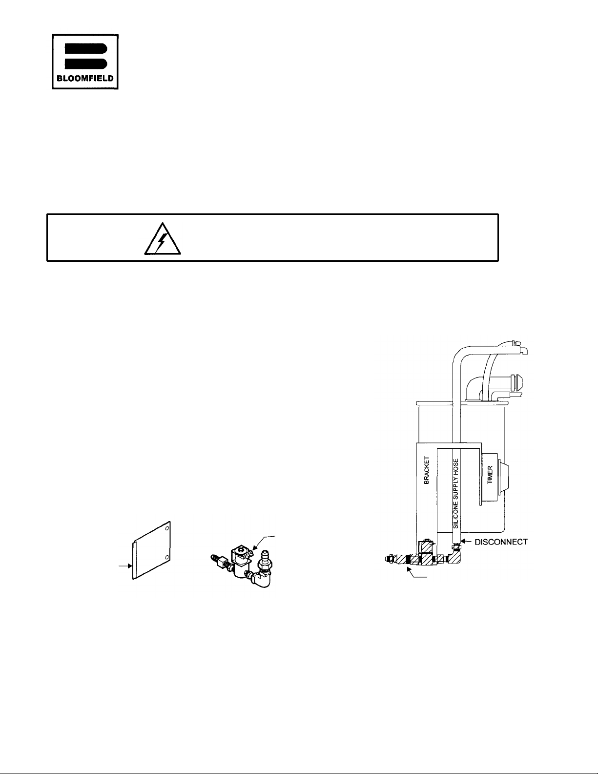
Disconnect wires to solenoid. Re
move silicone
d. Remove BRASS NUT from INLET FITTING.
Lift solenoid
/
timer
/
bracket
assembly from mounting clip.
e.
Loosen screws on bottom of solenoid and
separate solenoid from bracket.
Remove solenoid and fi
ttings from cabinet.
Note::
SOLENOID
REMOVE SHADED COMPONENTS
2 Erik Circle
Verdi, Nevada 89439 SOLENOID VALVE RETROFIT KIT
(775) 345-0444 84574 (120V) and 84575 (220/240V)
A. APPLICABILITY
This kit replaces the solenoid valve on automatic brewer models:
Koffee-King™ 8541 8573 Domestic and Export
CAUTION: ELECTRIC SHOCK HAZARD
Unplug brewer before beginning conversion
1. REMOVE EXISTING SOLENOID (See fig. B.1 and B.2)
a. Unplug brewer and shut off water supply.
SUPPLY HOSE from solenoid.
Reinstall bracket on mounting clip.
Integrity™ shown
Koffee-King™ similar
ACCESS DOOR
Fig. B.1
p/n 74536 Rev. (-) 040500cps Page 1 Of 3
ASSEMBLY
Fig. B.2
* SOLENOID ACCESS DOOR
* SOLENOID AND FLOW CONTROL
* |N LET FITTING, TEE & ADAPTERS
Page 2
B. INSTALLATIONS (continued)
ROUTE HOSES
Fig.
B.5
ATTACH PLASTIC
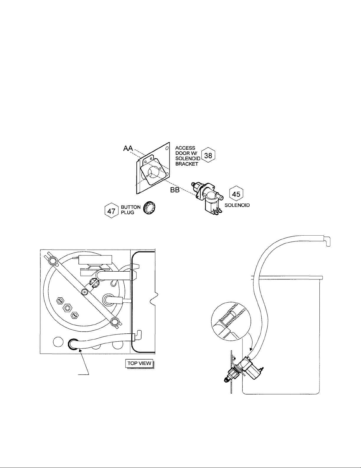
2. INSTALL NEW SOLENOID (See figure B.3, B.4 and B.5)
a. Assemble the SOLENOID BRACKET to the new ACCESS DOOR. Assemble the SOLENOID to
the SOLENOID BRACKET.
b. Route the silicone SUPPLY TUBE through the 3rd hole (from the front) then out the access door
opening. Attach tube to SOLENOID. Push the tube fully onto the outlet of the solenoid coil.
c. Assemble the ACCESS DOOR / SOLENOID to the cabinet. Connect wiring to the solenoid.
d. Turn wat er supply ON. Check for leaks.
e. Insert BUTTON PLUG in the hole formerly occupied by the inlet fitting.
f. Reinstall TOP PANEL and FRONT PANEL. Plug unit in and test.
AS SHOWN
Fig. B.3
HOSE TO OUTLET
WITH SOLENOID:
* PUSH HOSE FULLY
AGAINST VALVE
BODY
p/n 74536 Rev. (-) o405oocps page 2 of 3
Fig. B.4
Page 3

PARTS LIST: KITN0.84574 120V BREWER W/FAUCET
PARTS LIST: KIT NO. 84575 240V BREWER W/FAUCET
ITEM SERV P/N DESCRIPTION QTY
38 84412 SOLENOID ACCESS DOOR 1
38 84413 SOLENOID BRACKET 1
45 83612 SOLENOID ASSY, 120V 1
47 8810-12 BUTTON PLUG, ½” DIA 1
AA
BB
SCREW, FLT PHL SS 8-32 x ½” 2
SCREW, PAN SLT SS 4mm x 6mm 2
ITEM SERV P/N DESCRIPTION QTY
38 84412 SOLENOID ACCESS DOOR 1
38 84413 SOLENOID BRACKET 1
45 84569 SOLENOID ASSY, 240V 1
47 8810-12 BUTTON PLUG, ½” DIA 1
AA
BB
SCREW, FLT PHL SS 8-32 x ½” 2
SCREW, PAN SLT SS 4mm x 6mm 2
p/n 74536 Rev. (-) 040500cps Page 3 Of 3
 Loading...