

Page 1
OPERATING INSTRUCTIONS
MAINTENANCE INSTRUCTIONS
and
PARTS LIST
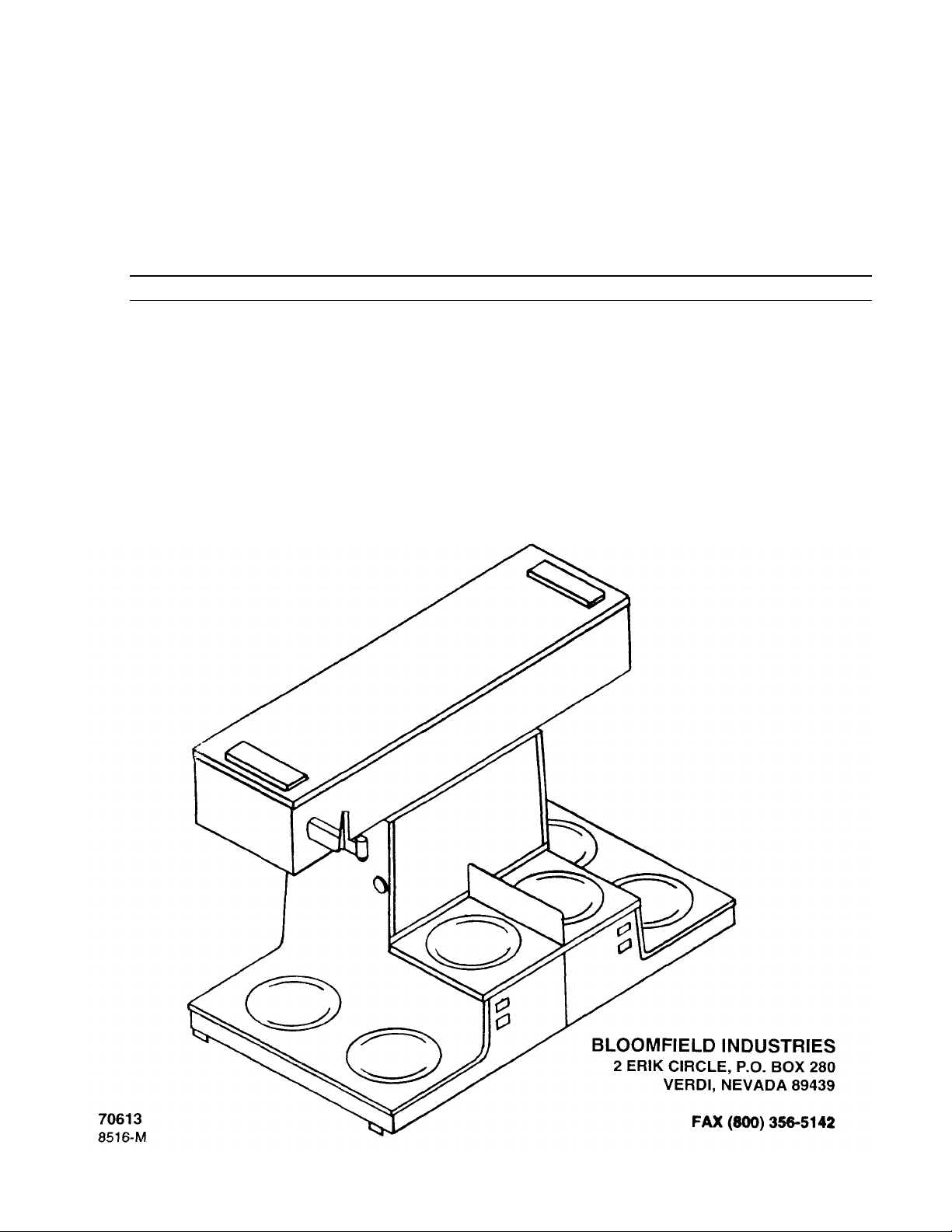
DUAL BREWERS WITH WARMING UNITS
BREWER Model Nos. 8516 and 8518
INTEGRITY
Brewing Systems
OWNER'S MANUAL
COVERING
Page 2
INDEX
MODEL NO.
8516
SKETCH
2 INTRODUCTION and PRE
-
INSTALLATION
3 ELECTRICAL INSTRUCTIONS
4 CONNECTING TO WATER
5 INITIAL BREW CYCLE SET UP
6
BREWING OF COFFEE
7
SERVICING INS
IDE THE BREWER
8
WATER FLOW DIAGRAM IN THE UNIT
8
EXPLODED VIEW
9 REPLACEMENT PARTS LISTING
10,11, 12
ITEMS NOT SHOWN and ACCESSORIES
12
CAUSE and EFFECT CHART
13, 14, 15, 16, 17,18, 19
WIRING DIAGRAM
— MODELS
8516
and
8518
20
ADDITIONAL SERVI
CE INFORMATION, SOLENOID
&
FAUCET
21, 22
CONTENT PAGE NO.
MODEL NO. 8518 SKETCH FRONT COVER
The INTEGRITY BREWERS have been designed with adjustment flexibility to cover a wide
spectrum of customer needs. Adjustments on the running thermostat and inlet timer are simple
adjustments easily accomplished by the purchaser, but NOT COVERED UNDER ANY
WARRANTY SERVICE AGREEMENT.
Brewers must be installed in accordance with installation instructions in the owner's manual for the
warranty to be valid.
WARNING:
DO NOT PLUG IN OR ENERGIZE THIS UNIT
UNTIL INSTALLA TION INSTRUCTIONS ARE READ
AND FOLLOWED.
2
Page 3

INTRODUCTION TO THE UNITS
There are two (2) styles of brewers covered in this
manual.
The "front loading" MODEL 8516 is a unit that positions to the rear of the counter and is completely
operated by store personnel. All operations such as
brewing, keeping coffee warm, serving coffee and
drawing of hot water are performed from the front of
the unit.
A companion "rear loading" MODEL 8518 is a unit
that may be positioned at the front of a counter. This
unit differs from MODEL 8516, as the hot water faucet
and the warmer stations remain at the front of the unit,
while the brewing and control functions have been
placed in the back of the brewer making operation of
the unit easily available, and a step saver for store
personnel.
MODEL 8516 and 8518 UNITS:
A. Bot h units have two (2) independent brewing
sections in each brewer,
1. One brewing section has a water faucet
for drawing cups of hot water while the
other section is for brewing only.
2. In either unit, one brewing section can be
used alone or both may be used at the
same time.
3. Each unit has six (6) warmer stations for
keeping decanters of coffee hot and
available.
4. All Brew Chambers and Decanters are
readily interchangeable between section
to section of a brewer or from brewer to
brewer.
5. Each brewing station of a unit requires a
separate:
a. Power source of 115/230 Volts, A.C.,
60 Hertz, SINGLE PHASE, Four(4)
Wire Supply capable of handling a
20 AMP load.
b. Water input line connected to a single
water source hose line of 3/8"
minimum size.
PRE-INSTALLATION INSTRUCTIONS
GUIDE TO THE INITIAL INSTALLATION and TANK FILLING SEQUENCE.
1. Check the Tank Heater Switch in both brewing sec tions of the unit to be sure it is in the OFF position.
They must remain OFF from Step 1 thru Step No.
9. A Tank Heater Switch controls the main heating
element in each brewing section of the unit, and it
must not be energized before the tank is filled with
water, thru Step No. 5. The Tank Heater Switch
also serves to de-energize the Brew Start Switch,
preventing brew cycles of cold water while the
Tank Heater Switch is in the OFF position.
2. Connect each brewing section of the unit to a
power source, see Electrical Installation on Page 4.
3. Connect each brewing section of the unit to the
water supply line, see instructions on Page 5.
4. Slide both Brew Chambers in place and SET AN
EMPTY DECANTER UNDER EACH BREW
CHAMBER.
5. Pour a full decanter of water thru the pour-in
door on top of each brewing section of the unit.
Wait two (2) minutes and repeat. Repeat a third
time for the non-faucet brewing section of the
unit. Water will start flowing into the decanter
during the third cycle (second cycle from water
faucet brewing sec tion) indicating that the tank
is filled with water.
6. After water flow stops, remove, empty and
replace the decanter under each brew chamber.
7. Plug in both power cords to the source
receptacles. Water should be connected to the
unit and ready to go. Recheck and correct any
leaks.
8. Turn on electric and water at source.
9. NOW — PRESS BOTH TANK HEATER
SWITCHES TO ON position and leave them
ON.
10. Proceed with initial Brew Cycle Set -up
Instruction on Page 6, and then to Brewing of
Coffee.
3
Page 4
ELECTRICAL INSTALLATION for MODELS 8516 and 8518
IMPORTANT: Prior to starting the electrical hook-up, check
power source and electrical receptacle for proper single
phase voltage supply. Figure 3 details the power
requirements of each brewing section of a unit.
CAUTION: DO NOT CONNECT TO A THREE (3) PHASE
POWER SOURCE OR ANY OTHER THAN AS NOTED
IN FIGURE 3, AS DAMAGES TO THE UNIT CAN
OCCUR THAT ARE NOT THE RESPONSIBILITY OF
THE MANUFACTURER OF THE UNIT
There are two (2) independent brewing sections in each
unit, and each brewing section draws 20 AMPS of power.
Each brewing section must be connected to a separate
power source, capable of supplying:
115/230 Volts, A.C. 60 Hz., Single Phase, four (4) Wire, 20
AMP service.
For power line cord, use #12 gauge wire suitable for 75
degrees C. All wiring must be in accordance with local
electrical codes.
1. Do not assume the GREEN earth ground wire
can be used as a neutral. The GREEN earth
ground is a protection circuit not intended as
part of the power lines.
2. Recheck at this point — the tank heater and
operation switch, on the front panel of each
brewing sec tion of the unit, must be in the OFF
position.
3. To install power cords, remove rear and bottom
cover panels of the unit for access to the power
junction blocks. See Figure 3. A separate
power cord must be wired into each junction
block thru either the rear or thru the bottom
opening. If bot tom access is to be used,
remove the two (2) snap-in Plug Buttons, and
transfer them to the power cord entrance holes
in the rear of the unit.
4. Recheck the Tank Heater Switch in each
section — it must be in the OFF position. Plug
in both power cords, check voltages at both
terminal blocks to be certain each conforms to
Figure 3 designations.
NOTE: At this point, unplug each power
cord and go to Step 3 of Initial
Installation Instruction Guide.
4
Page 5
CONNECTING WATER SUPPLY LINE TO THE UNIT
Complete the electrical installation
before starting the water connections.
WARNING:
DO NOT PLUG IN OR ENERGIZE THIS UNIT
UNTIL INSTALLATION INSTRUCTIONS ARE
READ AND FOLLOWED.
Before starting water hook-up, check to be sure both power
cords of the unit are unplugged.
Unit must be installed on a water line with a flowing
pressure between 20 PSI and 90 PSI. If water pressure
does not fall into this range, or varies greatly a pressure
regulator should be installed.
IMPORTANT: Flush the water line a minimum
of three (3) minutes before connecting to the
unit. The unit should be connected to COLD
WATER.
Each brewing section connects to a short length
of 1/4" O.D. tubing, preformed to go beneath the
unit. Each preformed tube connects to a 1/4"
Male Flare leg of a "TEE" fitting. The remaining
leg of the "TEE" fitting is a 3/8" Male Flare that
connects to a single 3/8" incoming water supply
line, as shown in Figure 4.
After water hook -up is completed, continue to
follow Pre-lnstallation Guide Instructions No. 4
thru 10.
5
Page 6
INITIAL BREWING CYCLE SET-UP
and OPERATION GUIDE
1. Unit is now connected to power and water. Both
water tanks have been filled. The Tank Heater
Switch on each brewing section is in the ON position and the water is heating in both brewing
sections.
2. On Water Faucet Section of each unit, draw off an
ounce or two of water from the faucet, two or
three times during the initial tank heating process,
to relieve air and expansion pressure in the hot
water faucet lines. This relieves "spitting with
pressure," when a cup of hot water is drawn from
a newly installed unit.
3. Initial heating time, at start up, will range from six
(6) to eight (8) minutes. The GREEN signal light
will turn ON when the water reaches brewing
temperature.
4. When GREEN signal light turns ON, press brew
start switch. Hot water will start to flow
immediately and assure that the tank and system
are full of water.
C. Turn Timer adjusting knob: The Timer is
very sensitive, so make adjustments one
(1) mark on the dial at a time. A one (1)
mark change on the dial approximates
three (3) ounces of water delivery change.
The factory timer set ting is 38 seconds
when the unit is operated on a flow
pressure of 35 PSI to receive a 60 ounce
water delivery.
1. Clockwise to INCREASE water
volume, delivered during a brewing
cycle or
2. Counter-clockwise to DECREASE the
delivery.
D. Repeat Steps 4 and 5 until desired amount
of water is dispensed during a brewing cycle.
5. Repeat Step 4. After water stops flowing, you
should have a full decanter of water — 60
ounces. In each brewing sec tion, a water flow
control valve and factory preset timer, control the
exact amount of water to be delivered during
each brewing cycle. If, after completing Step 4
the second time, the decanter is not full — 60
ounces of water, or tends to overflow, proceed as
follows:
A. Check water supply line flowing pressure.
Brewer will not operate properly if the line
pressure is below 20 PSI. (You may obtain
your PSI pressure by inserting a gauge in the
incoming water line at the back of the unit).
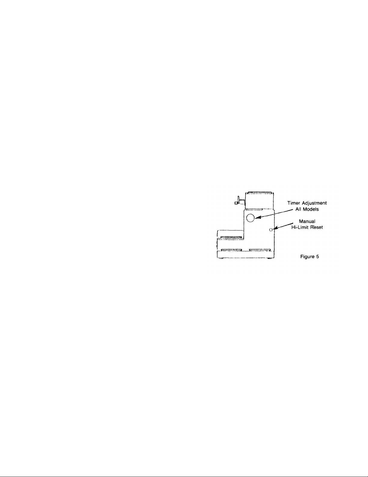
B. Remove the 2" Plug Button from access hole in
the cabinet front panels. Timer Knob and Face
Plate are in clear view for easy adjustment.
LEVELING THE UNIT
A very important installation operation that must
not be overlooked or ignored, is the "Leveling of
the Unit." For proper unit operation, it is very
important that the unit be level when it is standing
in its proper operating position.
After adjustment of both brew-sections is
completed and the GREEN signal lights have
turned ON, you are ready to brew coffee.
6
Page 7
BREWING OF COFFEE
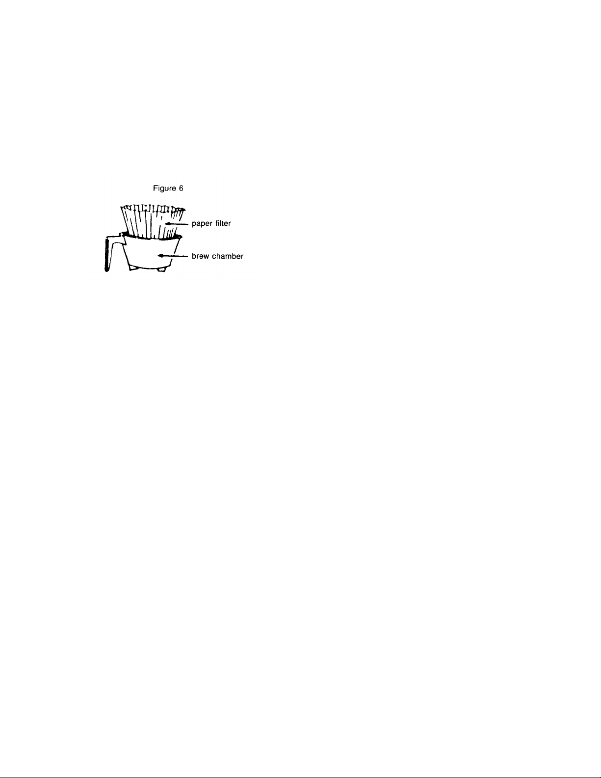
1. Remove brew chamber from under Spray Head
and place one (1) Paper Filter into Brew
Chamber. Add your choice of a premeasured
package of FINE GRIND coffee. Shake Brew
Chamber to level off coffee.
NOTE: Use 1-1/2 to 2-1/2 ounces to begin
brewing. Then, if stronger coffee is desired,
use more (to taste) of fine grind coffee. Slide
Brew Chamber in place.
3. Press Brew Switch. Hot water will start
spraying over coffee grounds in Brew
Chamber and coffee will start filling the
decanter. When coffee stops flowing, the
freshly brewed coffee is completed.
IMMEDIATELY remove Brew Chamber and
discard paper filter and used grounds.
4. When GREEN signal light relights again,
Brewer will be ready for another brewing
cycle.
To keep your coffee warm, the Brewers are
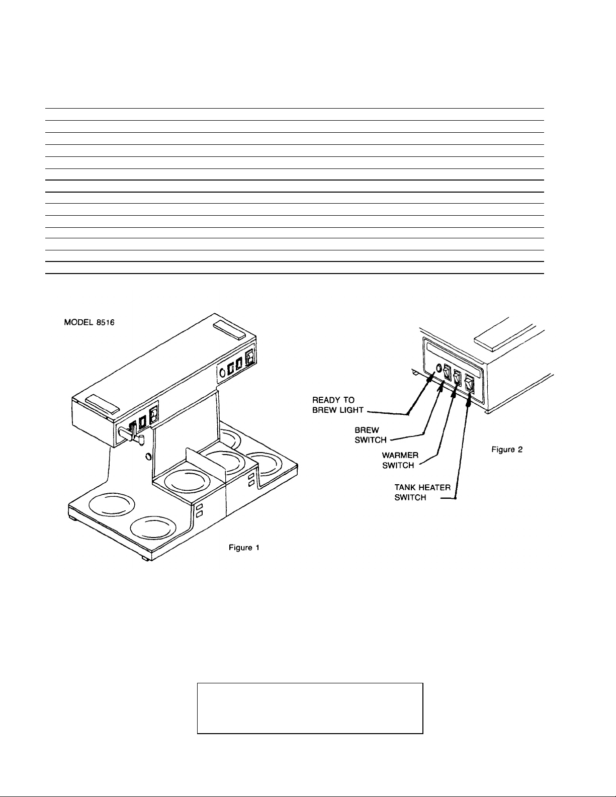
equipped with electric warmers which are
activated by a switch. A Red signal light will glow,
indicating WHICH warmer is ON.
2. Place empty decant er under Brew Chamber.
IMPORTANT: ALWAYS USE EMPTY
DECANTER BEFORE STARTING A BREW
CYCLE.
IMPORTANT:
1. Warmers should be turned OFF when not in
use.
2. Do not leave empty decanter on warmer that is
ON.
Page 8

SERVICING INSIDE THE UNIT
To expose the timer, high limit thermostat, switches
and wiring, etc. inside a unit section, the front panel
must be removed.
To Remove Front Panel:
A. Turn the two (2) pedestal warmer cover plates
counter-clockwise to remove them.
B. Remove the two (2) screws and clips from each
warmer well that holds the front panel in place.
C. Gently pull the front panel forward and lift it off
exposing the unit inside.
WATER FLOW DIAGRAM
PART I
Sequence of Operations:
WATER FLOW FOR BREWING OPERATION
(Both Brewing Sections)
1. Pushing brew Start Switch energizes the Timer.
The Timer then energizes the Solenoid Valve,
allowing water to flow into the Basin Pan and then
into the Hot Water Tank. The length of time the
Solenoid Valve is energized is controlled by the
Timer setting.
2. The water entering the Hot Water Tank from the
Basin Pan, flows to the bottom of the Tank
through the Water Inlet Tube.
3. The addition of water into the bottom of the Hot
Water Tank causes the hot water at the top of the
Tank to flow out through the Outlet Elbow of the
Tank Cover, to the Spray Head.
PART II
Sequence of Operations:
WATER FLOW FOR FAUCET OPERATION
(Faucet Section Only)
1. The incoming cold water supply connects to a "T"
Inlet Fitting on the Unit. Water flows from the "T"
Inlet Fitting through the Inlet Tube, Needle Valve
and Formed Inlet Tube into the input connection of
the Water Coil.
2. The Water Coil is submerged in the Hot Water
Tank and draws heat from the surrounding hot
water. Water flowing into the Water Coil is then
heated and flows out through the Formed Outlet
Tube to the Faucet. (The water flowing through the
Water Coil, which feeds the Faucet is not controlled by the Solenoid Valve. This portion of the
system is always under pressure and is controlled
by the Faucet. Opening the Faucet allows the
water to flow through the Water Coil system.)
3. The Needle Valve, in the system, controls the
volume of flow from the Faucet and is adjusted to
allow a gentle stream of water to be dispensed
through the Faucet, without splashing into the cup.
(The Faucet is intended as a cup to cup hot water
supply.)
NOTE: Drawing hot water from the Faucet,
during a Brewing Cycle does not affect the
volume of the finished brew.
8
Page 9

EXPLODED VIEW
for
MODEL NOS. 8516 and 8518
9
Page 10

REPLACEMENT PARTS LIST — MODELS 8516 and 8518
includes
#12, #13,
and #14
35 8881-8 Washer
2
L & R L & R
NOTE: FACING THE OPERATOR CONTROLS, DETERMINES LEFT
OR RIGHT BREWER DESIGNATION.
EXPL.
VIEW
REF.
PART DESCRIPTION
1 8707-4 Filter Support Frame 2 L& R L & R
2 8707-3 Screw, #10-32x5/16 Hex Hd. 2 L & R L & R
3 8707-2 Bakelite Handle, Black 2 L & R L & R
4 8516-131 Basin Cover, Sub-Assembly 1 Common Common
5 8543-46 Hinge Cover 2 L & R L & R
6 8543-49 Hinge Cover Wire 2 L& R L & R
7 8543-52 Screw, #8-3/8" Ph. Hd. "B" 30 L & R L & R
8 8043-506 #8-32 Hex Cap Nut 4 L & R L & R
9 8043-5 Hold Down Strap 2 L & R L & R
10 8043-47 Screw, Ph. Hd. #10-32x1" 2 L & R L & R
11 8551-250 Faucet Assembly, 1 L R
12 8551-100A Washer 1 L R
13 8551-100B Ext. Toothed Lockwasher 7/16 1 L R
14 8551-100C Hex Lock Nut 1 L R
15 8516-130 Formed Outlet Tube, to Faucet 1 L R
16 8718-31 Green Pilot Light 2 L & R L & R
17 8707-28 Brew Start Switch 2 L & R L & R
18 8516-25 Main Switch-Lighted Style Series 2 L & R L & R
19 6710-23 ON/OFF Lighted Switch, Black 6 L & R L & R
20 8540-4 Formed Inlet Tube Assy., to Input. 1 L R
21 8551-30 1/4" M. Flare to 1/8" FPT Connector 1 L R
22 8514-26 Needle Valve 1 L R
23 8543-23 Tinnerman Nut 30 L & R L & R
24 8516-136 Formed Tube Assy., to Needle Valve 1 L R
25 8516-142 Water Inlet Hose 2 L & R L & R
26 8941-20 Adaptor Fitting 4 L & R L & R
27 8541-48A 1/4" M. Flare x 1/4" FPT Elbow 2 L & R L & R
28 8541-120F Flow Control, 1/4" MPT x 1/4" MPT 2 L & R L & R
29 8541-120 Solenoid Valve, incl. #28 2 L & R L & R
29A D 20002-3 Screw, #10-32 x 5/16" 4 L & R L & R
30 8706-102 Reducer Adaptor 1/8 M x 3/8 FPT 2 L & R L & R
31 8516-102 Street Elbow 3/8 P.T. 1 L R
32 8551-35 "T" Fitting 2 x 1/4" M. Flare x 3/8 MPT 1 L R
33 8710-10 Hex Nut, 7/16-20 x 1/8" 2 L & R L & R
34 8541-93 Inlet Fitting 1/4" M. Flare x 3/8 MPT 1 R L
QTY.
PER
UNIT
MODEL USED ON
8516
BREWER
LEFT/RIGHT
BREWER
LEFT/RIGHT
8518
36 8043-30 Gasket 6 L & R L & R
37 8873-12 M. Elbow 1/4" Pipe x 1/4" M. Flare 2 L & R L & R
38 8541-21 Basin Pan 2 L & R L & R
39 8512-41 Seal Washer 2 L & R L & R
40 3-100 #6-32 x 1/4" Rd. Hd. Screw 4 L & R L & R
41 8512-51 Thermostat 2 L & R L & R
10
Page 11
73 8516-101 Front Panel
1 R L
REPLACEMENT PARTS LIST — MODELS 8516 and 8518
NOTE: FACING THE OPERATOR CONTROLS. DETERMINES LEFT
OR RIGHT BREWER DESIGNATION.
EXPL.
VIEW
PART DESCRIPTION
REF.
42 8043-8 Inlet Elbow 2 L & R L & R
43 8043-15 Vent Tube 2 L & R L & R
44 8043-11 Outlet Elbow 2 L & R L & R
45 8043-26 Water Outlet Tube 2 L & R L & R
46 8043-13 Sprayer Elbow 2 L & R L & R
47 8543-42 Sprayhead Gasket 2 L& R L & R
48 8543-44 Sprayer Disc 2 L & R L & R
49A 8514-68 Tank Cover Plate ONLY, Watercoil Style 1 L R
49B 8552-180 Tank Cover Plate ONLY, Non-Watercoil 1 R L
50 8043-12 Tank Cover Gasket 2 L & R L & R
51 8543-73 #4-40 x 1-1/2" Pan Hd. Screw 2 L & R L & R
52 8043-24 Water Inlet Tube 2 L & R L & R
53 8543-74 #4-40 Hex Nut 2 L & R L & R
54 8716-1 Heat'g Element 3500W, 230 V 2 L & R L & R
55 8043-28 1/2-20 Hex Nut 4 L & R L & R
56 8941-21 7/16-20 Hex Nut 1/8" thick 2 L R
57 8942-33 Seal Gasket 2 L R
58 8551-53 7/16" I.D. x 3/4" O.D. Stainless Steel Washer 2 L R
59 8540-6 Hot Water Coil 1 L R
60 8043-10 Tank Body 2 L & R L & R
61 7200-6X #8-32 x 5/16" Screw 2 L & R L & R
62 8861-16 #6-32 Hex Nut 4 L & R L & R
63 8718-48 Hi-Limit Bracket 2 L & R L & R
64 8552-50 Safety Thermostat 2 L & R L & R
65 8718-1 Timer w/Knob & Dial — 2 min. 2 L & R L & R
66 8718-1 A Timer Knob 2 L & R L & R
67 8700-16 Warmer Cover Plate, Black 6 L & R L & R
68 8572-18 Calrod Warmer Element, 100W, 120V. 6 L & R L & R
69 8033-60 Dot Plug Button, 3/8" Diameter 2 L & R L & R
70 8706-75 Plug Button, 2" Diameter 2 L & R L & R
71 7506-30 #8-32 x 3/8" Thread Cutting Screw 8 L & R L & R
72 8543-80 Front Panel Mount'g Clips 8 L & R L & R
QTY.
PER
UNIT
MODEL USED ON
8516
BREWER
LEFT/RIGHT
8518
BREWER
LEFT/RIGHT
74 616-5 #6-32 x 1-1/4" Rd. Hd. Screw 4 L & R L & R
75 8552-18 Terminal Block 2 L & R L & R
76 8516-116 Bottom Plate 1 Common Common
77A 8033-55 Leveler Leg 4 L & R L & R
77B 8033-56 Leveler Leg Cap 4 L & R L & R
78 8516-119 Warmer Top Assembly 1 Common Common
79 8516-100 Front Panel 1 L
80A 8516-105 Body Assembly 1 Common Common
81A 8516-122 Basin Sub-Assembly 1 Common —
81B 8518-102 Basin Sub-Assembly 1 — Common
11
Page 12
REPLACEMENT PARTS LIST — MODELS 8516 and 8518
2
1
8541
-
120JS
Solenoid Repair Kit
8544
4"
Leg Kit (Set of
4)
NOTE: FACING THE OPERATOR CONTROLS, DETERMINES LEFT
OR RIGHT BREWER DESIGNATION.
MODEL USED ON
EXPL.
VIEW
PART DESCRIPTION
REF.
82 8518-3 Front Label w/Faucet Hole 1 L 83 8516-2 Front Label without Faucet Hole 1 R L & R
84 8707-160 Brew Chamber Cup ONLY 2 L & R L & R
8707-6
85 8705-36 Plug Button, 7/8" Diameter 2 L & R L & R
86 8543-69 Heyco Bushing 8 L & R L & R
87 8516-107 Tank Support Bracket 1 Common Common
88 8516-134
89 8516-133 Access Door, Wiring 1 Common Common
90 8516-135 Bottom Access Door, Wiring 1 Common Common
Complete Brew Chamber, includes #1,
#2, #3, and #84
Solenoid Access Door
QTY.
PER
UNIT
8516
BREWER
LEFT/RIGHT
L & R
Common
BREWER
LEFT/RIGHT
L & R
Common
OPTIONAL ACCESSORIES (not shown)
8518
8551-275 Faucet Repair Kit
8707-6
8717-300 Complete Tank Lid Assembly, w/AII Components mounted onto it, FOR NON-FAUCET STYLE
8716-300 Complete Tank Lid Assembly, w/AII Components mounted onto it, FOR FAUCET STYLE BREWER
— Connector Kit — to attach both Brewing Sections of a Unit to a Single 3/8" Cold Water Source, FLEX— Connector Kit — to attach both Brewing Sections of a Unit, to a Single 3/8" Cold Water Source FLEX-
Complete Brew Chamber Assembly, w/wire rack
BREWER SECTION.
SECTION.
LINE. (For Unit without 4" legs).
LINE (For under the Unit Coupling, Unit stands on 4" legs).
12
Page 13

TROUBLESHOOTING GUIDE
plug in power
ed, reset breaker or
must
Check switch continuity, if switch does not make and
but blows fuses
AMP power
replace fuses
It is very important, when servicing equipment, to:
1. Define the basic Problem.
2. Isolate the Probable Cause.
3. Take Corrective Action regarding those items
hampering proper operation of the equipment.
It is usually relatively easy to define the basic
problem, but sometimes very difficult to pinpoint the
precise cause.
A TROUBLESHOOTING GUIDE is provided in this
chapter to suggest probable causes and corrective ac
PROBLEM PROBABLE CAUSE CORRECTIVE ACTION
tions for each. Obviously, if the cause is not
isolated and corrected, proper operation of the
equipment cannot be restored.
Should the problem remain after exhausting the
troubleshooting steps suggested, refer to the
Order/ Service Information section of this
chapter.
WARNING: Inspection, testing and repair of
electrical equipment should be performed only by
qualified service personnel. The brewer should
be unplugged when servicing, except when
electrical tests are required.
DANGER: Use extreme care during electrical
circuit tests. Live circuits will be exposed.
1. Unit electrically dead. No
power in unit or at terminal
block.
2. Unit has power but will not
start a cycle.
3. Unit has power but will
operate only while "Brew
Button," is held in contact.
Cycle stops when button is
released.
A. Power Cord. 1. Power cord not plugged into source —
cord.
B. Source Circuit Breaker or
Fuse.
C. Source receptacle miswired. 1. Check receptacle for proper power distribution at
A. Unit connected to wrong
power source.
B. Loose wire or connection. 1. Check for loose wire or connection.
C. Main Switch. 1. Switch is in OFF position — turn ON.
D. Brew "START" Switch. 1.
A. Loose wires. 1. Timer not being energized due to a loose wire —
B. Timer. 1. Timer blown due to hookup to wrong power —
1. Blown fuse or circuit breaker tripp
replace blown fuse.
terminals.
1. Check power source — correct wire hookup —
be A.C., 120Volt/208 to 240Volt, Single Phase.
Reattach loose wire or tighten connection,
2. Electrically open — replace.
3. Switchbutton stuck — replace.
break when activated — replace.
reattach wire.
correct power supply — replace timer.
2. Timer defective — replace.
4. Unit operates
or trips circuit breaker.
A. Under rated fuses or circuit
breakers.
1. Each unit must operate on a separate 20
line. 15 AMP fusing will not operate —
or circuit breakers, use 20 AMP rated line protectors.
13
Page 14
PROBLEM PROBABLE CAUSE CORRECTIVE ACTION
4. Unit operates but blows fuses
Remove extra appliances, each brewer requires a 20
straighten the line or replace line
clockwise to reduce the water dump
movement of the timer knob One (1) mark on the dial
or trips circuit breaker.
flows into the basin pan or
from the faucet.
flows into basin pan. Water
does flow from the faucet.
B. Too heavy a load on the line.
(Excessive demand).
A. Water Supply. 1. Water supply line valve shut off — turn on. 5. Unit activates but no water
B. Line filter such as QC7
and/or strainer.
C. Restricted water line. 1. Water line to unit plugged — clear blockage or
A. Loose Wire. 1. Locate loose wire and attach. 6. Unit activates but no water
B. Solenoid Valve (not
opening).
1. Other appliances added onto same power line.
AMP power line
1. Water line filter plugged up — replace filter.
2. Strainer plugged up — back flush or replace.
replace line.
2. Kink in water line —
section
3. Water line in cold area, water frozen in the line —
warm up the line so water flows freely,
1. Solenoid valve coil electrically open — replace coil.
2. Foreign material in solenoid — clean inside of
solenoid valve.
3. Shut off piston seat or spring damaged — replace
both or complete solenoid.
7. Too little water or too much
water. (Decanter short or
overflows)
C. Twisted or Kinked Hose
(from solenoid to basin pan).
A. Strainer or water filter
cartridge is clogged.
B. Timer Adjustment (Timer
needs to be adjusted).
C. Flow Restricter in Output
End of Water Solenoid
Valve. (Dirty, missing,
damaged or inoperative)
1. Relieve twist or kink in hose — reposition on basin
pan fitting.
1. Back flush strainer or replace. 2. Replace water filter
cartridge.
1. To receive a full decanter, adjust the timer to run a
shorter or longer time cycle. To increase water
volume, turn timer knob clockwise for a longer cycle
time, or countercycle time.
NOTE: At 35 PSI water flow, into the unit, a change of
three (3) ounces in delivery occurs with each
face.
2. Check timer cycle with a stop watch, if cycle time is
irregular — change timer.
1. Particles of foreign material may partially or
completely clog the orifice of the flow restricter.
Clean or replace flow regulator or change complete
solenoid valve assembly.
14
Page 15

PROBLEM PROBABLE CAUSE CORRECTIVE ACTION
free operation. Wide varying water pressures
Starting with some liquid in
versa
1/2 minutes, therefore a second
Check inside surface of water solenoid valve port.
Basin Pan. (Water flow stops
7. Too little water or too much
water. (Decanter short or
overflows)
8. Water keeps running into
Basin Pan. (Will not shut off
with Power Cord unplugged)
D. Water Pressure Variations
(Water pressure rises
above 85 PSI or falls below
20 PSI.)
E. Decanter —
1) Wrong Size
2)
decanter.
3) Correct decanter used
but second brew cycle
initiated before first run
off is completed.
A. Water Solenoid Valve
(Plunger stuck open)
1. All automatic brewers require a constant water
pressure between 20 PSI and 85 PSI for consistent
[roublelead to erratic delivery. A pressure regulator may be
needed to stabilize high or fluctuating running
pressures. A water source that falls below 20 PSI
may result in short pots or erratic water volume
delivery.
1. Customer using a foreign decanter too small to
hold volume of liquid being delivered or vice— use correct decanter.
2. Start with an empty decanter every cycle, as any
coffee left in decanter will cause overflow.
3. Water flow into basin pan takes approximately 38
seconds but the run, thru the coffee to complete a
brew, takes 3 to 3brew cycle must not be started until the first cycle
has been completed.
1. Check and clean inside of water solenoid valve
and plunger.
2.
If it is scored, chipped or damaged, replace the
complete solenoid valve.
9. Water keeps running into
when Power Cord is
unplugged.)
10. Water keeps running or
dripping from Spray Disc
(Solenoid Valve not leaking
into Basin Pan).
A. Brew "START SWITCH" 1. Check brew switch for operation. If switch does not
B. Timer 1. Check timer for TIME CYCLE operation. If timer
C. Shorted Wiring (Wires from
start switch shorted
together).
A. Tank Temperature (Set too
high).
3. Check plunger seat surface if worn or damaged,
replace the plunger and spring or replace complete
solenoid valve.
make and break contact, replace switch
does not cycle to OFF condition and brew "Start
Switch" is good, replace timer.
1. Locate and remove the contact — replace wire
where necessary.
1. Adjust thermostat to lower temperature. Tank
temperature should be between 195 and 204
degrees F. To decrease tank temperature, turn the
thermostat adjusting shaft counter-clockwise.
NOTE: A 10 degree turn of thermostat shaft is
equal to a 4 degree F temperature change in the
water. Always run 2 or 3 cycles to climatize water
temperature and new thermostat setting.
15
Page 16

PROBLEM PROBABLE CAUSE CORRECTIVE ACTION
Brewer does operate. Water
must go out indicating thermostat is calling for heat.
replace
locate and reconnect.
clockwise to decrease the temperature. A 10
nd
10. Water keeps running or
dripping from Spray Disc
(Solenoid Valve not leaking
into Basin Pan).
is cold.
B. Hot Water Coil leaking.
(Faucet side only)
A. Loose Wire. 1. Check for loose connection — locate and reattach. 11. Water fails to heat, but
B. Thermostat adjust ment.
(Ready Light is ON)
C. Tank Heater 1. Check for voltage at Tank Heater Terminals. Voltage
1. Shut off needle valve controlling water to Hot Water
Coil. If running or dripping from Spray Disc stops,
replace Hot Water Coil.
1. Thermostat adjustment shaft turned down. Turn
thermostat shaft clockwise to the stop, Ready Light
If Ready Light does not go out — replace thermostat.
2. If Ready Light does go out, allow water to heat and
then adjust thermostat for a water temperature
between 190 to 200 degrees F, as it exits directly
under the Brew Chamber, taking it about one (1)
minute into the cycle.
should be between 208 Volts and 240 Volts,
depending on source. If voltage is present —
element.
12. Ready Light fails to glow
when water reaches
brewing temperature.
13. Water heats but does not
get hot enough.
D. Source Fuse or Circuit
Breaker.
A. Ready Light 1. Check for disconnected wire —
A. Thermostat. (Out of
adjustment, Ready Light
does come ON)
2. If voltage is not present on element terminals, check
Items 11 A, 11B and 11D.
1. One (1) fuse or circuit breaker is open, not
completing the Heater Element circuit — change
fuse or activate circuit breaker.
2. If thermostat cycles ON and OFF and Ready Light
does not glow — replace ready light.
1. Temperature of water out of the brew chamber must
be 190 to 200 degrees F. Turn thermostat shaft
clockwise to increase the water temperature or
counterdegree turn of the thermostat shaft makes a 4
degree F water temperature change.
2. If thermostat shaft is turned clockwise to the stop a
temperature is still too low — replace thermostat.
16
Page 17

PROBLEM PROBABLE CAUSE CORRECTIVE ACTION
terminals. It should be within 10% of unit rating plate.
adjust or
e Brew
14. Water heats, but takes a
long time. (Slow Recovery)
15. Water Temperature
TOO Hot.
Also Called:
• Steaming
• Boiling
• Overheating
16. Dry Coffee Grounds, All
grounds not getting wet in
Brew Chamber (after a
brew cycle has been
completed.)
A. High Lime Deposits. 1. Delime unit. (Consult a qualified service technician.)
B. Low Voltage at Source. 1. Check voltage at receptacle and at heater element
If a low voltage condition exists, an electrician
should be consulted. A low voltage condition can
and does cause frequent service calls, as well as
extending the water heating time.
A. Thermostat 1. Thermostat out of calibration or defective —
replace. To decrease tank temperature, turn the
adjustment shaft counterclockwise. If Ready Light
does not come ON, the thermostat is defective,
replace it.
A. Spray Disc and/or Gasket
missing.
B. Filter Paper (Paper weave
too porous).
1. Check Spray Disc. The Spray Disc and Gasket must
be properly in place to break up the water stream
and completely wet coffee grounds.
1. Use proper filter papers to insure correct time for
contact of water and coffee in the Brew Basket.
C. Improper loading of th
Chamber.
17. Coffee Grounds do not get
wet. Water stays in Basin
Pan or Pan overflows,
and/or water leaks out of
the bottom of brewer body.
18. Weak Coffee A. Too much water. 1. V erify water level in decanter. Delivery should be 60
A. No Siphon Action. 1. Check for obstruction in elbow connections from
B. Leak in Water Path from
Water Input to final outlet at
Spray Disc.
1. Filter should be centered in the Brew Chamber and
the bed of coffee grounds should be level.
Basin Pan to Tank Cover and Outlet Elbow and
Tube to Spray Disc. 2. Check Tank Lid openings for
lime buildup restricting water flow.
1. Check for correct fit and/or leakage at:
a. Solenoid Valve and Fitting.
b. Water Input Tubing from Solenoid Valve to Basin
Pan.
c. Tank Cover Gasket.
d. Elbows and Tube connections from Basin Pan to
Spray Disc.
Oz. Adjust Timer for correct water delivery — (see
Installation Instructions.)
17
Page 18

PROBLEM PROBABLE CAUSE CORRECTIVE ACTION
(should be between 190 and 200 degrees F). Adjust
1. Filter Paper must be centered in Brew Chamber and
Improper Filter Paper can restrict water flow through
proximately three (3)
r drips, install a
18. Weak Coffee.
19. Strong Coffee.
B. Temperature of water too
low.
C. Improper loading of Brew
Chamber.
D. Not enough coffee grounds
in Brew Chamber.
A. Not enough water. 1. Verify water level in decanter. Delivery should be 60
B. Two (2) Filter Papers or
improper Filter Paper.
1. Check temperature of water out of Spray Disc
thermostat to proper temperature. (See Thermostat
Adjustment Procedure.)
Coffee ground bed must be level.
1. Verify coffee ground weight. Be sure to use the
proper measure of coffee grounds.
Oz. — adjust Timer for correct water delivery. (See
Installation Instructions).
1. Use only one (1) recommended Filter Paper.
coffee bed, causing over extraction, resulting in
strong, bitter coffee.
C. Too much coffee grounds in
Brew Chamber.
20. Overflowing Decanter.
Occasionally, not every
time.
22. Faucet keeps dripping. A. Foreign material inside the
A. Receiving Decanter not
empty when a brew cycle is
started.
B. Water pressure is fluctuating. 1. See: 7D "Water Pressure Fluctuations."
A. Incoming water source shut
off.
B. Needle Valve Shut -off
(between water inlet "T"
fitting and water tank.)
faucet valve seat preventing
faucet seat from shutting off
water flow completely.
1. Verify coffee ground weight. Be sure to use the
proper measure of coffee grounds. Average volume
is 1-1/4 to 3 ounces of cof fee grounds.
1. Always start a brew with an empty receiving
Decanter under Brew Chamber.
1. Check and be sure the water source valve is open. 21. No Water from Faucet.
1. The needle valve must be open to permit water flow
through the faucet, setting is ap
full turns from a closed condition. (The needle valve
is also used to adjust the force of the water stream
from the faucet.)
1. Shut off water supply, disassemble and clean the
faucet valve seat. If faucet still leaks o
complete repair kit. If faucet continues to drip, the
seat has been damaged, replace Faucet Assembly.
18
Page 19

PROBLEM PROBABLE CAUSE CORRECTIVE ACTION
1. Check Warmer Element for continuity. If no continuity
minutes.
24. Warming Plates will not
heat.
does not light.
A. Use of two (2) Filter Papers
or improper Filter Paper.
B. Lime Deposits in Brewer. 1. Check Elbows and Water Outlet Tube for lime
A. Warmer Switch. 1. Switch OFF, turn ON.
B. Warmer Element.
A. Loose Wire. 1. Locate loose wire and re-attach Terminal. 25. Glow Light inside Switch
B. Burned out Neon Glow
Lamp. (Switch works, but
light does not glow.)
1. Use only one (1) recommended Filter Paper. 23. Brew Time Exceeds 4-1/2
deposits or BLOCKAGE.
2. Check tank lid openings for lime deposit or foreign
material blockage.
3. Delime Elbows and/or Unit. (Consult a qualified
Service Technician.)
2. Check Warmer Switch for proper operation. If it
does not make and break load circuit — replace
Switch.
is present, replace Warmer Element.
1. Remove complete lighted Switch and replace.
19
Page 20

WIRING DIAGRAM
For
MODEL NOS. 8516 and 8518
NOTE: All wiring 16 gauge, except where noted.
This diagram is the same for Models 8516 and 8518, and covers both brewing sections of the units.
20
Page 21

ADDITIONAL SERVICE INFORMATION
Vacuum Pac consists of:
Ref. #29 COLD WATER ENTRANCE SOLENOID VALVE PART NO. 8541-120
Consists of Valve and Flow Control
SOLENOID VALVE REPLACEMENT PARTS
(For Blue Coil Valve)
(1) 8541-120C Coil Assembly — 120V.
(2) 8541-120K Solenoid Repair Kit
(3) 8541-120F (3A) Flow Control
(4) 8541-120WS (2D) Service Wrench
(5) 8810-103 Solenoid Valve Only
(No Kit Parts Sold Separately)
(2A) Spring
(2B) Plunger
(2C) Seal Ring
(Minus 2D & 3A)
(1) 8541-120CS Coil Assembly — 120V.
SOLENOID VALVE REPLACEMENT PARTS
(For Black Coil Valve)
(No Kit Parts Sold Separately)
(2) 8541-120JS Solenoid Repair Kit
(3) 8541-120KS Solenoid Overhaul Kit
(4) 8541-120F (3A) Flow Control
(5) 8541-120WS (2D) Service Wrench
(6) 8810-103 Solenoid Valve Only
Vacuum Pac consists of:
(2A) Spring
(2B) Plunger
(2C) Seal Ring
(2D) Service Wrench
Vacuum Pac consists of:
(2A) Spring
(2B) Plunger
(2C) Seal Ring
(2D) Service Wrench
(3A) Flow Control
(Minus 2D & 3A)
21
Page 22

ADDITIONAL SERVICE INFORMATION (Cont'd.)
HOT WATER FAUCET
REPLACEMENT PARTS LIST
Ref.
No. Part No. Description A. 8706-169B Handle, Red
1. 8551-275 Repair Kit (sold as Kit only) 3. 8551-100A Washer Rubber
A.
B.
C.
D. Kit "0" Ring — #6, #7 & #8 6. 8551-200B "0" Ring Stem Seal 5/16" O.D.
E. Contains Tee Nut 7.
F.
G.
H.
Handle (Color — Red) 4. 8551-100B 7/16 External Tooth Lock Washer
Valve-Stem 5. 8551-100C Hex Lock Nut
Valve Disc
Spring 8.
Guide C. 8551-275A Valve Disc
Bushing
Instruction Card (Not Shown) 9. 8551-200E Adapter Tool — Service Wrench
2. 8551-275B Stream Straightener (Not Shown)
8551-200A "0" Ring Seal 1/4" O.D.
8551-200C "0" Ring Spout Seal 3/8" O.D.
SEALS AVAILABLE
TOOL AVAILABLE
22
 Loading...