

Page 1
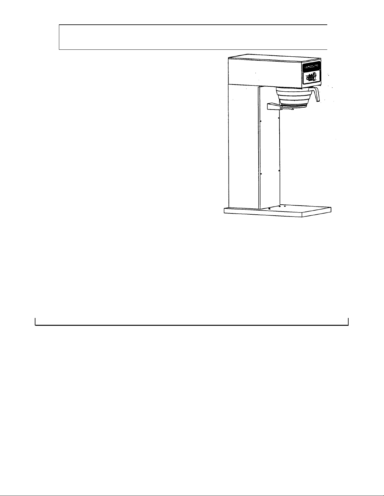
BLOOMFIELD 3-5-6 GALLON TEA BREWER
MODEL NO. 8356BLT
BY
BLOOMFIELD
BLOOMFIELD INDUSTRIES
2 ERIK CIRCLE
P.O.BOX 280
VERDI, NV 89439
U.S.A.
FAX (800) 358-5142
PH (702) 345-0444
INTRODUCTION
INSTALLATION INSTRUCTION
INITIAL OPERATING INSTRUCTION
BREWING INSTRUCTION
WIRING DIAGRAM
PARTS IDENTIFICATION
EXPLODED VIEW
SERVICE INFORMATION FOR SOLENOIDS
ORDERING PROCEDURE
WARRANTY
72659 Rev ( -)
TABLE OF CONTENTS
PAGE 1
PAGE 2
PAGE 3
PAGE 4
PAGE 5
PAGE 8
PAGE 7
PAGE 8
PAGE 9
PAGE 10
This machine will brew 3,5 & 6 Gallons of beverage and is factory pre-set at 3 Gallons.
Printed in April 1996
Page 2
INTRODUCTION BLOOMFIELD MODEL 8356BLT HI-
QUALITY 3-5-6 GALLON TEA BREWER
Thank you for purchasing a Bloomfield Tea Brewer. You will achieve maximum performance from this unit if
you familiarize yourself with its many outstanding features. Please take a few minutes to read through the
owner's manual. Proper installation is very important if maximum performance and satisfaction are to be
achieved. If you have any difficulties, consult your nearest Bloomfield Authorized Distributor. They have the
required expertise to provide the proper advice and assistance. If the Bloomfield Distributor is unable to assist
you, please contact the factory directly.
Please be certain the electrical connections are compatible, as improper connections could damage the
Brewer and void the warranty.
Safe and satisfactory operation of your Bloomfield Brewer depends to a great extent upon its proper
installation. This Tea Brewer must be installed without alteration and in accordance with these printed
instructions and applicable electrical codes. The performance and safety of the Brewer can be greatly
impaired if it is altered in any way, or if installation deviates from the instructions printed herein, and will not be
covered under any warranty service agreement.
This Bloomfield Brewer has been designed with adjustment flexibility to cover a wide spectrum of
customer needs.
Page 3

INSTALLATION INSTRUCTION
READ THIS COMPLETELY BEPORE STARTING THE INSTALLATION
WARNING: DO NOT plug In or energize this unit until Installation Instructions are read and followed.
To enable the installer to make a quality installation and hold delay time to a minimum, the following
suggestions and tests should be done before the actual unit installation is begun.
LEVELING THE UNIT
Set Tea Brewer in operating location and level. For proper unit operation, it is very important that the unit be
level when it Is standing in its proper operation position. A spirit level should be place on the top plate of the
unit, at the edge, as a guide when making level adjustments. Level the unit from left to right and front to back
by turning the adjustable feet that support the unit.
PLUMBER'S INSTALLATION INSTRUCTION
NOTE: This equipment must be installed to comply with the Basic Plumbing Code of the Building Officials and Code
Administrators International, Inc (BOCA) and the Food Service Sanitation Manual of the Food and Drug
Administration. (FDA)
Flush water line before connecting to Brewer. Brewer should be connected to COLD WATER line
NOTE: Bloomfield recommends 1/4" copper tubing for installation of less than 25 feet and 3/8" for more than 25 feet
from the 1/2" water supply line.
A water shut-off valve should be installed on the incoming water line in a convenient location.
Unit must be installed on a water line with a flowing pressure between 20 PSI and 90 PSI. If water pressure does not
fall into this range or varies greatly, a pressure regulator should be installed in the water supply line.
Check the termination of the water line where the Brewer will stand. (The water line must terminate into a 1/4' flare
fitting). Be sure to use pipe sealant (approved for potable water) on the male threads of the fitting to prevent water
leak. Do not use the many varieties of liquid or pasted pipe dope, as it may leech out of the threads, pass into, and
damage the unit.
Connect water line to 1/4' flare fitting on back of the unit. Turn on the water and check for leaks.
To delay build-up of lime deposits in water tank, we recommend the use of a Water Conditioner.
Filtration System may be required to delay lime deposits in water tank. Consult your Bloomfield
Representative for information.
2
Page 4

ELECTRICIAN'S INSTALLATION INSTRUCTIONS
WARNING: Brewer must be properly grounded to prevent possible shock hazard. DO NOT assume
a plumbing line will provide such a ground.
Unit requires a dedicated power source capable of supplying: 115 Volt, A.C„ 60 Hertz, Single Phase 15 Amp.
Service.
The unit is shipped from the factory with a 3-wire, 2-pole polarized power cord and cap attached.
NOTE: Make sure tank heater switch on front panel is in OFF position. Bottom portion of switch rocker should be
pressed in. Failure to turn off the element will damage the element and void warranty.
Plug unit into 110 -120 Volt grounded outlet, fused at 15 Amps.
INITIAL OPERATING INSTRUCTIONS NOTE:
Operations should be performed by a qualified installer.
Electrician's and Plumbe r's Instructions should be followed carefully before proceeding with
Initial Operating instructions.
Be sure all electrical and plumbing connections are tight.
Maker sure Tank Heater Switch on Front Panel is still in OFF position.
Place empty dispenser under the Tea Brewer.
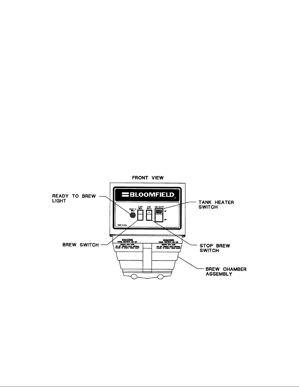
Press Brew Start Switch to initiate brewing cycle. This will energize the solenoid and will begin filling the tank.
When the solenoid stops filling the tank and water does not begin to flow from the spray disc, press the Brew Switch
again to continue filling the tank.
Press Brew Stop Switch when water begins to flow from spray disc.
Turn Tank Heater Switch to ON position. This will also activate bypass relay.
Allow 30 minutes for initial water heat up. Time will vary with incoming water temperature.
When tank water is up to proper temperature, the green READY TO BREW light will be lit.
NOTE: During the initial heat-up, some water may drip from spray disc. This is normal.
Discard all water in dispenser. Brewer is ready for use.
NOTE: Br ewer is factory pre-adjusted for Three (3) Gallons of beverage.
3
Page 5

BREWING INSTRUCTIONS
Place filter paper in Brew Chamber and add tea. Slide Brew basket into rails, pushing it to full back
stop location.
Contact your tea supplier for quantity required.
Press Brew Switch to initiate br ewing cycle.
Make sure drip-out is complete before removing Brew Chamber.
If for any reason there is a need to stop the brewing cycle before its completion, press the 'Brew Stop' switch. This
stops water flow to the Brew Chamber. The timing cycle is also canceled and timer resets to start.
Check Volume. To change the volume quantity, see 'Timer Adjustment Instructions' below.
TIMER ADJUSTMENT INSTRUCTIONS
NOTE: Operations should be performed by a qualified installer.
This Brewer was Pre-Adjusted at Three (3) Gallons.
Following to be done if it is necessary to adjust the timer to match dispenser
size.
All operating controls are accessible to Front Panel only.
1. Unplug power at source.
2. Remove the Front Panel by removing four (4) #8 Screws.
3. Adjust the setting on the timer on the left side of the unit to match dispenser
size.
NOTE: Some fine tuning maybe necessary.
4
Page 6

WIRING DIAGRAM (MODEL NO. 8356BLT)
5
Page 7

PARTS IDENTIFICATION
8808HLZ
6 GALLON TEA DISPENSER
82199
EVERPURE WATER FILTER BH
8601-5 COVER 5 GALLON TEA DISPENSER
(MODEL NO. 8356BLT)
ITEM SERVICE • DESCRIPTION QTY.
1 8043-83 THERMOSTAT HI LIMIT 1
? 8543-52 SCREW PHL SS 8 X 3/8 4
3 8812-73 CLIP BREW BASKET 1
4 8043-15 TUBE VENT 1
5 8707-2 HANDLE BLACK 1
6 8707-3 SCREW HEX 10 -32X5/16 1
7 82269
8 8043-11 ELBOW OUTLET 1
9 8543-23 NUT TNR Zl #8 4
- 10 8043-506 NUT ACR SS 8-32 2
11 8043-5 STRAP HOLD DOWN ASSY 1
12 8043-47 SCREW PAN 10 -32 X 1 1
13 8718-31 LIGHT PILOT GREEN 125V 1
14 8043-12 GASKET TANK COVER 1
15 8043-30 GASKET ELEM HTG i
16 8812-57 FITTING UNION 1/4x1/4/< 1
17 8710-10 NUT HEX BR 7/16-20 1/8 1
18 8746-38 TUBE OUTLET WATER 6 1/4 LG 1
19 8512-41 WASHER THERMO SEAL 5/16 OD 1
20 8043-28 NUT HEX BR 1/2-20 2
21 8033-55 LEG LEVELER PLATED 4
22 35-210 STRAIN RELIEF LQ TIGHT 1
23 8033-56 LEG LEVELER 4
24 8543-69 BUSHING SHORTY HEYCO 3
25 8596-4 CORD ASSY 1
26 8942-92 NUT KEP 8-32 13
27 7200-6X SCREW PAN PH SS 8-32X5/16 2
28 8706-20 TUBE VENT LONG 1
29 3-100 SCREW RND HD 6-32X1/4 PHL SS 2
30 8812-70 WASHER BEVELLED 1
31 7510-22 NUT HEX BR 1/2-24 1
32 8812-41 ELBOW OUTLET ASSY 1
33 8812-49 TUBE CONNECTOR 1 IN 1
34 8706-9 RACK WIRE BREW CHAMBER 1
35 82581 BASIN COVER 1
36 8746-34 TANK ASSY WATER TEA BREWER 1
37 8551-53 WASHER SS .035 X 7/161D X 3/40D 2
38 82388
39 82665 TANK COVER WELDED ASSY 1
40 82390 GROMMET FILL TUBE 1
41 9102-9 ELEM TANK HTG 120V 1675W 1
42 8707-55 SWITCH ROCKER BREW START 1
43 9102-8 ELBOW 1/4 FPT/HOSE 2
44 8514-88 COUPLING FLARE SWIVEL 3
45 8812-40 SWITCH NORM ON-MOMEN-OFF 1
46 9102-55 TEE 1/4 IN 3FL M-M/F 1
47 8781-32 ELBOW 1/8 MPT X 1/4 FLARE 2
48 82186 DISC SPRAY HEAD 1
49 82582 BASIN WLD ASSY 1
50 82206 BODY WLD ASSY 1
51 82657 PANEL FRONT 1
52 82211 BASE WLD ASSY 1
53 82214 SWITCH TANK HTR INDP LMP 1
54 82215 GASKET SPRAY HEAD 1
55 82216
56 9102-57 CHAMBER BREW 1
TUBE WATER OUTLET 37° .312 ID
FILL TUBE W/90° BEND
THERMOSTAT W/36° CAPILLARY
1
1
1
ITEM SERVICE • DESCRIPTION QTY.
57 82220 TIMER DELAY 0-60 SEC 1
58 81732 LEG LEVELER ASSY 1
59 82223 VALVE SOLENOID 120V .6 GPM 1
60 82224 VALVE SOLENOID 120V .15 GPM 1
61 82661
62 82239 CAP LEG VINYL 4
63 82241 FTG HOSE CONNECT STRAIGHT 1
64 82244 TIMER 12MIN W/35&6 FACE PLT 1
65 82245 STRAINER WATER NSF 1 '
66 82655 WATER SPOUT ASSY 1
67 82225 PLUMBING ASSY 1
68 9102-41 BREW CHAMBER ASSY 3/16 HOLE 1
69 82664 TANK COVER ASSY 1
TUBE WATER BYPASS 27°
OPTIONAL
ACCESSORIES
-1
8799HLZ 3 GALLON TEA DISPENSER
8804HLZ 5 GALLON TEA DISPENSER
82198 EVERPURE WATER FILTER MH
8600- 6 COVER 3 GALLON TEA DISPENSER
8806- 50 COVER 6 GALLON TEA DISPENSER
6
Page 8

EXPLODED VIEW
7
Page 9

ADDITIONAL SERVICE INFORMATION
(COLD WATER ENTRANCE SOLENOID VALVE) Part no. 82223 w/.60
GPM & Part no. 82224 w/.15 GPM
(1) 8541 -120CS (1A) Coil Assembly - 120V
(2) 8541-120K Solenoid Repair Kit
(3) 8541-120JS Solenoid Repair Kit
(4) 8541-126 Solenoid Overhaul Kit
REPLACEMENT COMPONENTS
Vacuum Pac consists of:
(2A) Spring
(2B) Plunger
(20 Seal Ring
Vacuum Pac consists of:
(2A) Spring
(2B) Plunger
(2C) Seal Ring
(2D) Service Wrench
Vacuum Pac consists of:
(2A) Spring
(2B) Plunger
(20 Seal Ring
(2D) Service Wrench
(3A) Plow Control .60
gpm
(5) 8541-115 Solenoid Overhaul Kit
(6) 82223A (4A) Plow Washer .60 gpm
(7) 82224A (4B) Flow Washer .15 gpm
(8) 8541 -120WS (2D) Service Wrench
KIT INSTALLATION INSTRUCTION:
1. Unscrew Nut (A) and set aside for later installation.
2. Lift Bracket (B) up along with Coil (C) and set aside for later installation.
3. Unscrew Part (D) by first placing a service wrench (2D) on part (D).
(Make sure service wrench mounts into both holes (E).
Set aside for later installation.
4. Refer to Diagram for Kit Part replacement.
5. Reassemble all parts as required.
6. Reinstall in Machine (Check direction of water flow) and check for leaks.
8
Vacuum Pac consists of:
(2A) Spring
(2B) Plunger
(20 Seal Ring
(2D) Service Wrench
(3B) Flow Control .15
gpm
Page 10

ORDERING/SERVICE PROCEDURE
Use only genuine Bloomfield replacement parts in this Brewer. The use of replacement parts other than those
supplied by Bloomfield voids the warranty.
To find the parts required to restore proper operation to the Tea Brewer, proc eeds as follows:
. 1. Refer to the exploded view located in this chapter to identify the
Ordering Information - Once the parts needed are known, record the following information from the
identification section:
How to order - for immediate shipment, call your local authorized BLOOMFIELD Parts Distributor.
Service Information - To obtain service assistance in addition to that contained in this chapter, call
BLOOMFIELD at (702) 345-0444
Be prepared to give the model and serial numbers of your Brewer, as well as the problem to the service
technician when calling for assistance.
parts needed.
2. Use the item number from the exploded view to locate the corresponding parts in the parts
identification and function of this chapter.
Part Number
Description
Quantity
9
Page 11

WARRANTY
For a period of one (1) year from date of installation, all defective parts on Bloomfield equipment will be
replaced free of charge, with exception that parts that become defective through accident, neglect, improper
installation, mishandling or damage in transit, or component damage caused by water supply systems pressure
and scale build up in water system.
BREWER WARRANTY IS VOID IF:
Other than genuine Bloomfield replacement parts are used.
Brewer is plugged into voltage other than specified on serial plate.
Tank Heating Element is energized before water tank is filled.
Recommended installation or servicing procedures are not followed.
Setting of circuit breakers, calibration of thermostats & timers are not covered by warranty.
10
Page 12

GENERAL LAYOUT DATA
BLOOMFIELD 3 TO 8 GALLON TEA BREWER MODEL:
8356BLT
ELECTRICAL
SPECIFICATIONS
MODEL WATTS VOLTS HZ AMPS SINGLE
6356BLT 1700 120 50/60 14.2
PHASE
11
 Loading...