

Page 1
10 Sunnen Drive
St. Louis, MO 63143
telephone: 314-678-6336
fax: 314-781-2714
www.bloomfieldworldwide.com
OWNERS MANUAL
for
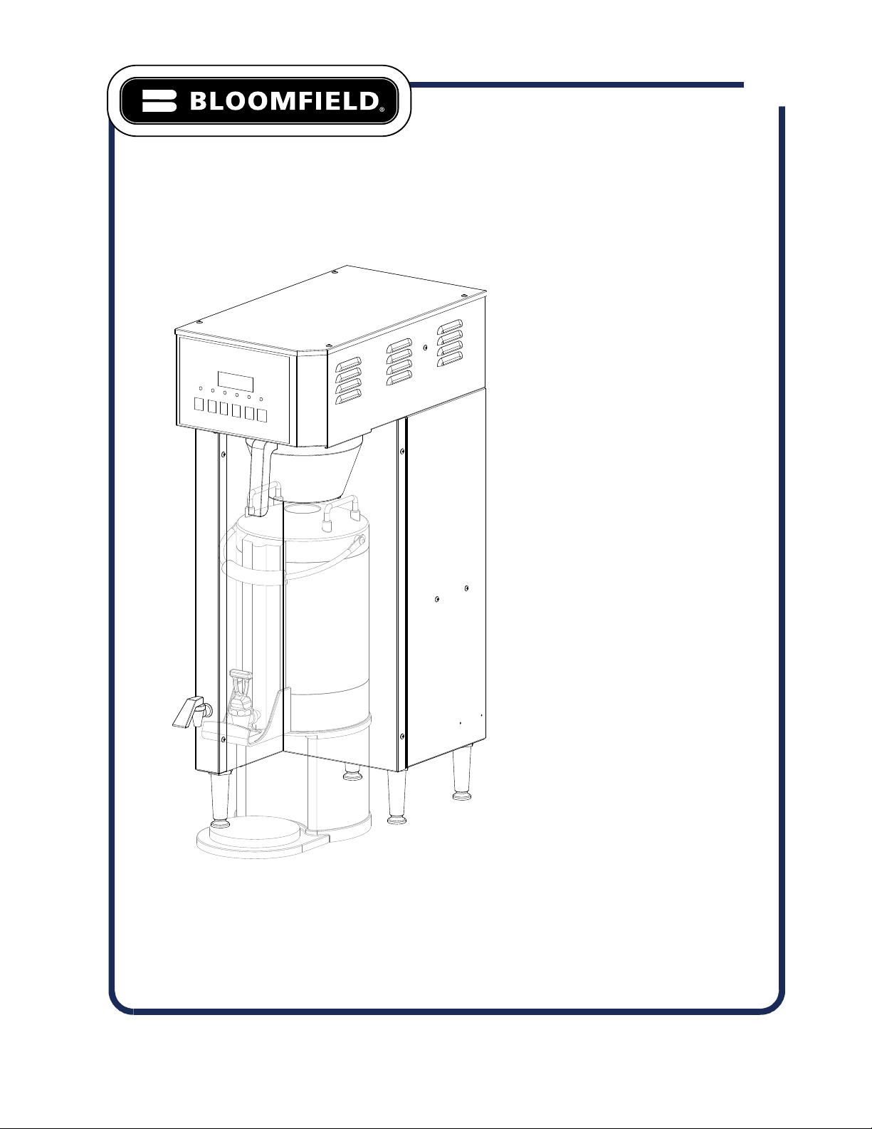
655
2795TF- SERIES
THERMAL
COFFEE BREWER
with
E-Max
CONTROL
MODEL:
2795TF
Includes:
Installation
Operation
Use & Care
Servicing Instructions
Exploded View & Parts List
Model 2795TF Single E-Max Thermal Brewer
p/n 2M-Z17970 Rev. C M655 140805
(Servers Sold Separately)
Page 2
WARRANTY STATEMENT
All equipment manufactured by Bloomeld is warranted against defects
in materials and workmanship for the time periods listed in the chart
starting from the date the equipment is placed into service and is for the
benet of the original purchaser:
THE FOREGOING OBLIGATION IS EXPRESSLY GIVEN IN LIEU
OF ANY OTHER WARRANTIES, EXPRESSED OR IMPLIED,
INCLUDING ANY IMPLIED WARRANTY OF MERCHANTABILITY
OR FITNESS FOR A PARTICULAR PURPOSE, WHICH ARE
HEREBY EXCLUDED.
BLOOMFIELD, LLC SHALL NOT BE LIABLE FOR INDIRECT,
INCIDENTAL OR CONSEQUENTIAL DAMAGES OR LOSSES
FROM ANY CAUSE WHATSOEVER.
This warranty is void if it is determined that upon inspection by an
authorized service agency that the equipment has been modied,
misused, misapplied, improperly installed, or damaged in transit or by re, ood or act of God.
It also does not apply if the serial nameplate has been removed or unauthorized service personnel perform service. The prices
charged by Bloomeld for its products are based upon the limitations in this warranty. Seller’s obligation under this warranty
is limited to the repair of defects without charge by a Bloomeld Authorized Service Agency or one of its sub-agencies. This
service will be provided on customer’s premises for non-portable models. Portable models (a device with a cord and plug or a
dispenser) must be taken or shipped to the closest authorized service agency, transportation charges prepaid, for services.
Agencies are located in principal cities, please visit our website to locate one.
This warranty is valid in the United States and Canada and void elsewhere. Please consult your classied telephone directory
or your food service equipment dealer; or, for information and other details concerning warranty, write to:
Service Parts Department; Bloomeld
10 Sunnen Drive, St. Louis, MO 63143
Phone: (314) 678-6336 : Fax: (314) 781-2714
Technical@ bloomeldworldwide.com / www.bloomeldworldwide.com
pour over, automatic coffee brewers 2 yrs. 2 yrs.
EBC, EMAX coffee brewers 2 yrs.* 2 yrs.
* EBC, EMAX coffee brewer control 3 yrs. no labor
POD coffee brewers 1 yr. 1 yr.
ECO coffee brewers 1 yr. 1 yr.
coffee warmers 1 yr. 1 yr.
tea brewers 2 yrs. 2 yrs.
tea dispensers 1 yr. 1 yr.
tea dispenser BBTea 1 yr. no labor
hot water machines 2 yrs. 2 yrs.
thermal servers 90 days no labor
airpots 30 days no labor
decanters no warranty no warranty
Equipment Parts Labor
BLOOMFIELD SERVICE POLICY AND PROCEDURE GUIDE ADDITIONAL WARRANTY EXCLUSIONS
1. Resetting of safety thermostats, circuit breakers, overload protectors, or fuse replacements.
2. All problems due to operation at voltages other than specied on equipment nameplates - conversion to correct voltage
must be the customer’s responsibility.
3. All problems due to electrical connections not made in accordance with electrical code requirements and wiring diagrams
supplied with the equipment.
4. Replacement of items subject to normal wear, to include such items as knobs and light bulbs. Normal maintenance
functions including adjustment of thermostats, microswitches, and replacement of fuses and indicating lights are not
covered under warranty.
5. All problems due to inadequate water supply, such as uctuating, or high or low water pressure.
6. All problems due to mineral/calcium deposits, or contamination from chlorides/chlorines. De-liming is considered a
preventative maintenance function and is not covered by warranty.
7. Full use, care and manuals may or may not be sent with each unit, only a condensed version. Please visit our web site to
download the full version.
8. Travel mileage is limited to fty (50) miles from an authorized service agency or one of its sub-service agencies.
9. All labor shall be performed during normal working hours. Overtime premium shall be charged to the customer.
10. All genuine Bloomeld replacement parts are warranted for ninety (90) days from date of purchase on non- warranted
equipment. Any use of non-genuine Bloomeld parts completely voids any warranty.
11. Installation, labor and job checkouts are not considered warranty.
12. Charges incurred by delays, waiting time or operating restrictions that hinder the service technicians ability to perform
services are not covered by warranty. This includes institutional and correctional facilities.
SHIPPING DAMAGE CLAIMS PROCEDURE
NOTE: For your protection, please note that equipment in this shipment was carefully inspected and packaged by skilled
personnel before leaving the factory. Upon acceptance of this shipment, the transportation company assumes full responsibility
for its safe delivery.
IF SHIPMENT ARRIVES DAMAGED:
1. VISIBLE LOSS OR DAMAGE: Be certain that any visible loss or damage is noted on the freight bill or express receipt,
and that the note of loss or damage is signed by the delivery person.
2. FILE CLAIM FOR DAMAGE IMMEDIATELY: Regardless of the extent of the damage.
3. CONCEALED LOSS OR DAMAGE: if damage is unnoticed until the merchandise is unpacked, notify the
transportation company or carrier immediately, and le “CONCEALED DAMAGE” claim with them. This must be done
within fteen (15) days from the date the delivery was made to you. Be sure to retain the container for inspection.
Bloomeld cannot assume liability for damage or loss incurred in transit. We will, however, at your request, supply you with the
necessary documents to support your claim.
Page 3
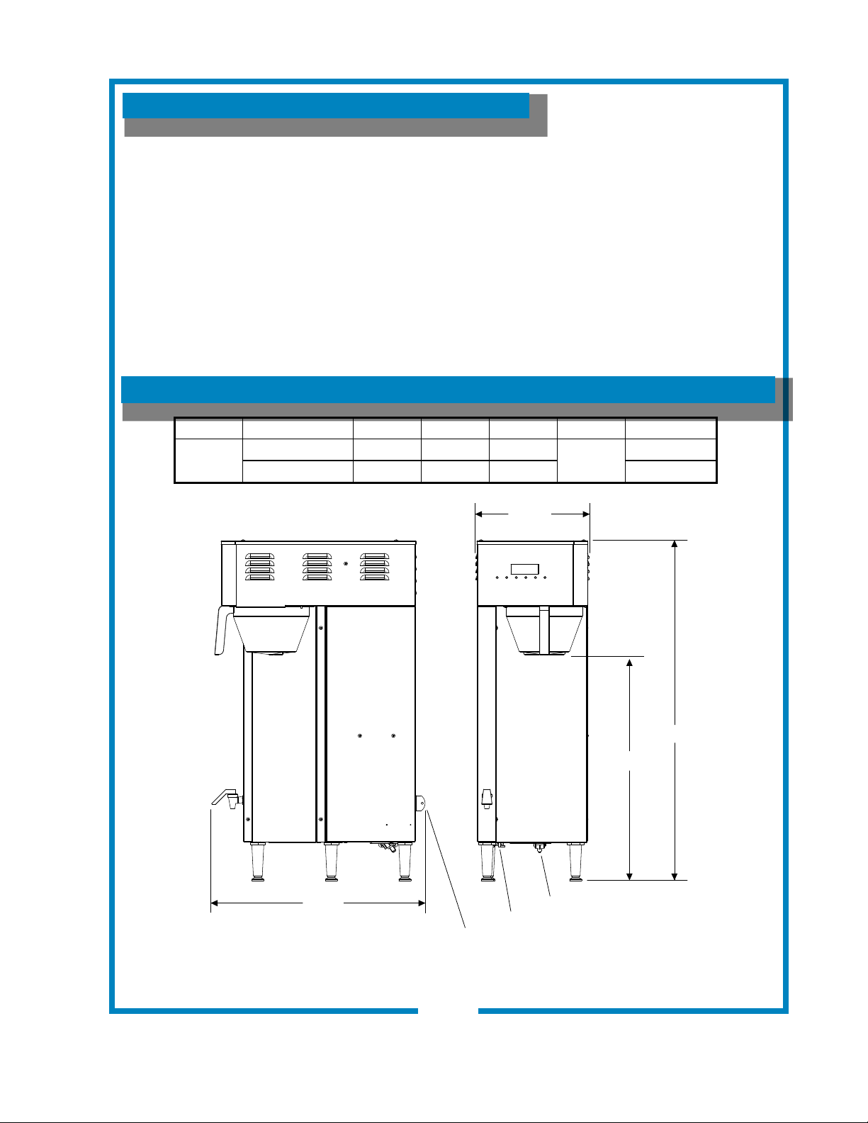
TABLE OF CONTENTS
WARRANTY STATEMENT xi
SPECIFICATIONS 1
FEATURES & OPERATING CONTROLS 2
GENERAL INFORMATION & PRECAUTIONS 4
AGENCY APPROVAL INFORMATION 4
INSTALLATION 5
OPERATION 6
CLEANING INSTRUCTIONS 10
SERVICING INSTRUCTIONS 12
TROUBLESHOOTING SUGGESTIONS 19
TM
E-MAX T
TEST PROGRAM 20
EXPLODED VIEWS 22
WIRING DIAGRAM 26
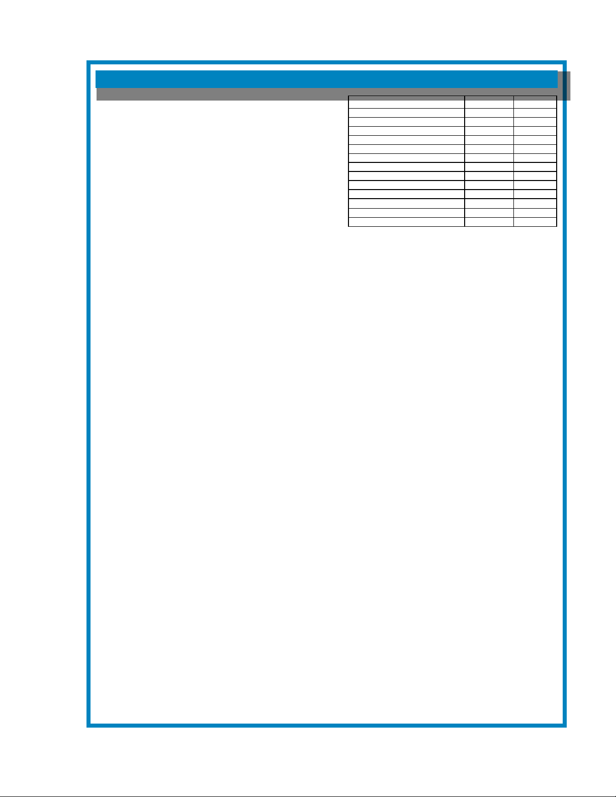
SPECIFICATIONS
Model Volts Hr Watts Amps Phase Power Cord
2795TF
120V 50/60 1550 12.9
120/240V 3/W N 50/60 3050 12.7 None
Thank You for purchasing this
Bloomeld appliance.
Proper installation, professional
operation and consistent
maintenance of this appliance will
ensure that it gives you the very
best performance and a long,
economical service life.
This manual contains the
information needed to properly
install this appliance, and to use,
care for and maintain or repair the
appliance in a manner which will
ensure its optimum performance.
1
11 13/16”
5-15P
23 7/16”
655 2M-Z17970 Owners Manual 2795 E-Max Thermal Brewer
655 2M-Z17970 Owners Manual E-Maxl Thermal Brewer
Electrical Inlet
On / Off Switch
2795TF SHOWN ABOVE
1
35 1/2”
23 9/16”
Water Inlet
IL2719
Page 4
FEATURES AND OPERATING CONTROLS
BREW HEAD
(BREW CHAMBER
REMOVED)
BYPASS
DIVERTER
BREW CHAMBER
ACCESSORIES
THERMAL
SERVER
HOT WATER
DRIP TRAY
CONTROL
PANEL
BREW
CHAMBER
HOT WATER
FAUCET
BREW
NOZZLE
SPRAY HEAD
GASKET
SPRAY
DISK
BREWER
Model 2795
ON / OFF
SWITCH
WATER
CONNECTION
CONTROL PANEL
VIEW
SCREEN
LED
INDICATORS
1st KEY
(START BREW)
2nd KEY
(CANCEL BREW)
3rd KEY
(POWER ON/OFF)
Fig 1. 2795 E-Max Thermal Brewing System; Features & Operating Controls
2
6th KEY
(LARGE VOLUME)
5th KEY
(SMALL VOLUME)
4th KEY
(STANDARD VOLUME)
IL2718
655 2M-Z17970 Owners Manual E-Maxl Thermal Brewer
Page 5

Brewer
Adjustable Legs
Brewing Controls
Bypass Valve
FEATURES AND OPERATING CONTROLS (continued)
Allows brewer to be leveled. Also allow clearance for cleaning
underneath brewer.
Start or stop brew and select brew volume.
Dilution water ows into brew chamber channel from here.
Dilution water DOES NOT ow through the coffee grounds.
Hot Water Faucet
Nameplate
Ready-To-Brew Light
System Switch
(not shown)
Brew Chamber
Brew Chamber
Bypass Diverter
Thermal Server
(sold separately)
Brew-Thru Lid
Handles
Nameplate
Serving Faucet
Sight Glass
Hot water dispensed here.
Lists manufacturer, model and serial number.
Also lists voltage and wattage rating of brewer.
Glows when the tank water is up to temperature.
Located on lower right rear of brewer.
Turns main power to brewer ON or OFF .
Holds coffee grounds during brew cycle.
Forms dilution ow channel by holding lter clear of the brew
chamber wall.
Allows entry of brewed coffee and dilution water into thermal.
Minimizes splashing in the event satellite is tipped.
Allow the thermal to be safely carried.
Lists manufacturer, model and serial number.
Fresh coffee dispensed from thermal brewer here.
Check the level of coffee remaining here.
Drip Tray
Drip Tray (optional)
655 2M-Z17970 Owners Manual E-Maxl Thermal Brewer
Catches drips and spills from the thermal server and the wafe
grid is easily removed for easy cleaning.
Optional drip tray catches drips and spills from hot water faucet.
Easily removed for cleaning.
3
Page 6
GENERAL INFORMATION AND PRECAUTIONS
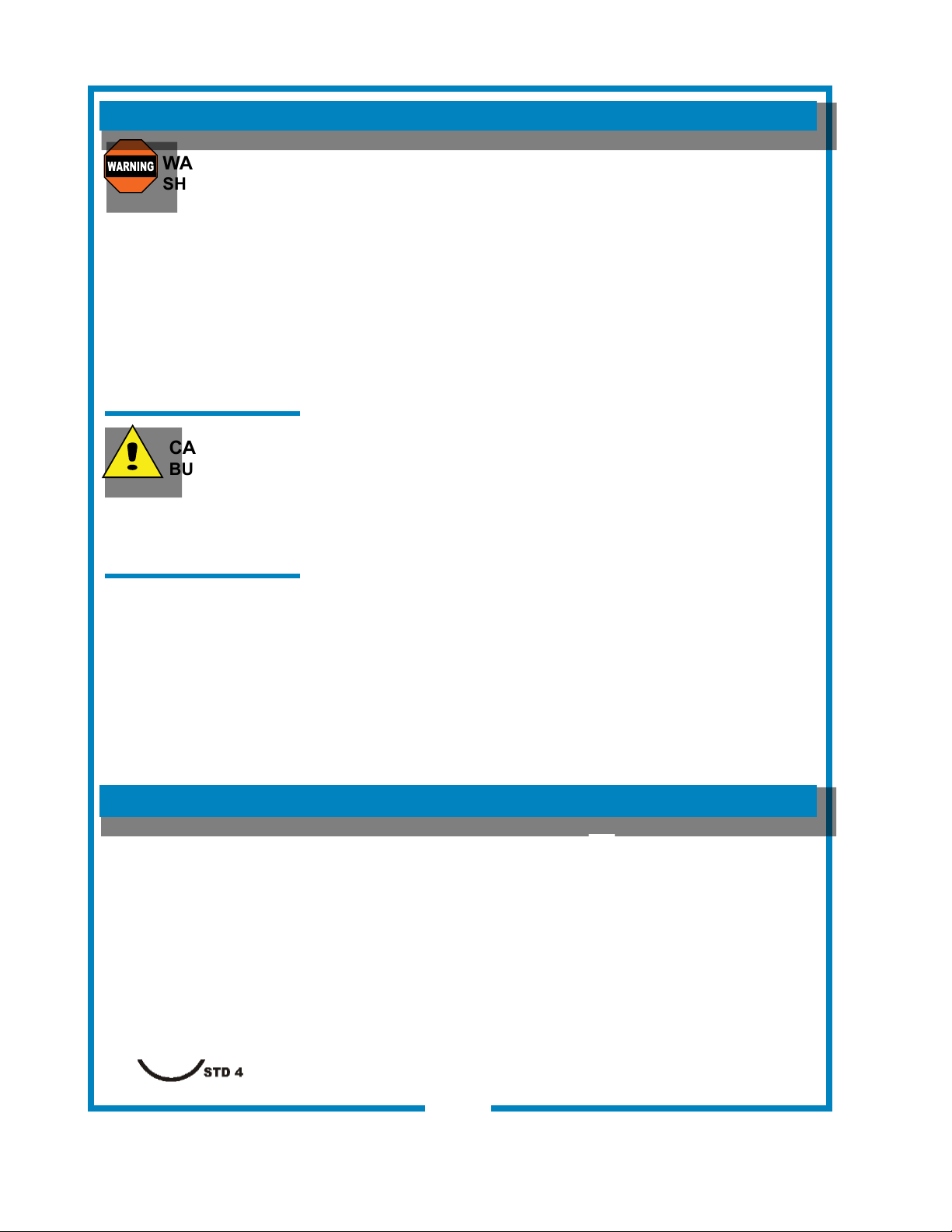
WARNING:
SHOCK HAZARD
All servicing requiring access
to non-insulated electrical
components must be
performed by a factory
authorized technician.
DO NOT open any access
panel that requires the use
of tools. Failure to follow this
warning can result in severe
electrical shock.
CAUTION:
BURN HAZARD
Surfaces of this brewer can
be hot and can cause burns
on contact.
This appliance is intended for use in commercial establishments
only.
This appliance is intended
for human consumption. No other use is recommended or authorized
by the manufacturer or its agents.
Operators of this appliance must be familiar with the appliance use,
limitations and associated restrictions. Operating instructions must be
read and understood by all persons using or installing this appliance.
Cleanliness of this appliance is essential to good sanitation. Read and
follow all included cleaning instructions and schedules to ensure the
safety of the food product.
Surfaces of the brewer, brew basket and servers can be hot to the
touch, and may cause burns on contact.
Disconnect the brewer from electrical power before performing any
maintenance or servicing.
DO NOT submerge servers in water.
DO NOT splash or pour water over, onto or into any controls,
control panel or wiring.
Any procedure which requires the use of tools must be performed by a
qualied technician.
This manual is considered to be a permanent part of the appliance.
This manual and all supplied instructions, diagrams, schematics, parts
breakdown illustrations, notices and labels must remain with the
appliance if it is sold or moved to another location.
This appliance is made in the USA. Unless otherwise noted, this
appliance has American sizes on all hardware.
to brew hot beverage, specically coffee,
AGENCY APPROVAL INFORMATION
This single thermal brewing system is listed under E9253
and listed under E9253.
This single thermal brewing system meets NSF Standard 4 only when
installed and maintained per the instructions in this manual.
655 2M-Z17970 Owners Manual E-Maxl Thermal Brewer
4
Page 7
INSTALLATION INSTRUCTIONS
INSTALL LEGS
The brewer is provided with 4” adjustable legs and rubber feet.
Be sure the legs are securely screwed into the base of the
brewer, and that the rubber feet are properly installed.
LEVEL THE UNIT
The adjustable legs allow the brewer to be leveled. Set the
brewer in its ultimate operating location and check for level with a
spirit level Adjust the brewer for level from front-to-rear, and from
side-to-side. Be sure all four feet rest rmly on the counter.
PLUMBER’S INSTALLATION INSTRUCTIONS
IMPORTANT:
This equipment must be installed in accordance with the Basic
Plumbing Code of the Building Ofcials and Code Administrators
International (BOCA), and the Food Service Sanitation Manual
of the Food and Drug Administration (FDA). Also, this equipment
installation must comply with all local plumbing codes and
ordinances.
IMPORTANT:
Brewer must be installed on a water line with a full-ow pressure
between 20 psi and 90 psi.
NOTE: If water pressure varies greatly, or exceeds 90 psi at any
time, a water pressure regulator must be installed. Plumbing
installer must supply the regulator.
Brewer must be connected to a portable water supply.
Bloomeld recommends not less than 1/4” copper tubing for
installations of 12’ or less, and not less than 3/8” copper tubing
for installations exceeding 12’. Brewer must be connected to a
COLD water line.
NOTE: DO NOT use a saddle tap for this water line connection.
A shut-off valve must be installed between the main water supply
and the brewer. Plumbing installer must supply the shut-off
valve. A 1/4-turn ball valve is recommended.
Bloomeld highly recommends the use of the provided water
strainer to help prevent deposits in the brewing system.
Flush the water line before connecting to the brewer.
ELECTRICIAN’S INSTALLATION INSTRUCTIONS
Brewer requires a dedicated single-phase circuit:
Model 2795TF 120/208-240 Volt AC, 50-60 Hz
22.9 / 25.2 Amp circuit
3-Wire (L1, L2, N plus Gnd)
NOTE:
To enable the installer to make
a quality installation and to
minimize installation time, these
tests and suggestions should be
completed before the actual
installation is begun.
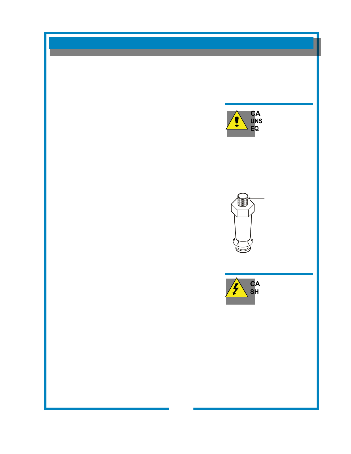
CAUTION:
UNSTABLE
EQUIPMENT HAZARD
Legs must be adjusted so that
all four feet rest rmly on the
counter. Failure to properly
install the feet can result in
movement of the brewer, which
can cause personal injury and/or
damage to the brewer.
SCREW INTO
BREWER
FRAME
ADJUST
FOR
HEIGHT
IL2596
Fig. 2 Adjustable Legs
CAUTION:
SHOCK HAZARD
Brewer must be properly
grounded to a reliable earth
ground to prevent possible
shock hazard. Do not assume
a plumbing line will provide such
a ground. Electrical shock may
cause serious injury.
655 2M-Z17970 Owners Manual E-Maxl Thermal Brewer
5
Page 8
OPERATION
OPERATING INSTRUCTIONS
IMPORTANT:
All E-Max T brewers are
tested and set at the factory. If
programming adjustments are
necessary, refer to the
E-Max Programming Manual
(p/n 2M-73674).
To over-ride the Brew Wait
mode, press and hold the
BREW key for 3 seconds when
the brewer is in Brew Wait
mode (i.e. when brew light is
ashing). The brew will proceed
immediately regardless of water
temperature. This feature
should only be used when
testing water volume, otherwise
the brew will proceed with the
water below the precise brew
temperature.
Note: the following safety
features have been incorporated
to prevent multiple unattended
brews:
The brew key is disabled during
a brew cycle. This minimizes
the possibility of double
brewing.
When the “Brew” light is on or
ashing, repeated pressing
of the BREW switch will be
ignored, (there will be a beep
each time it is pressed). A Brew
will only be activated when the
“Brew” light is off.
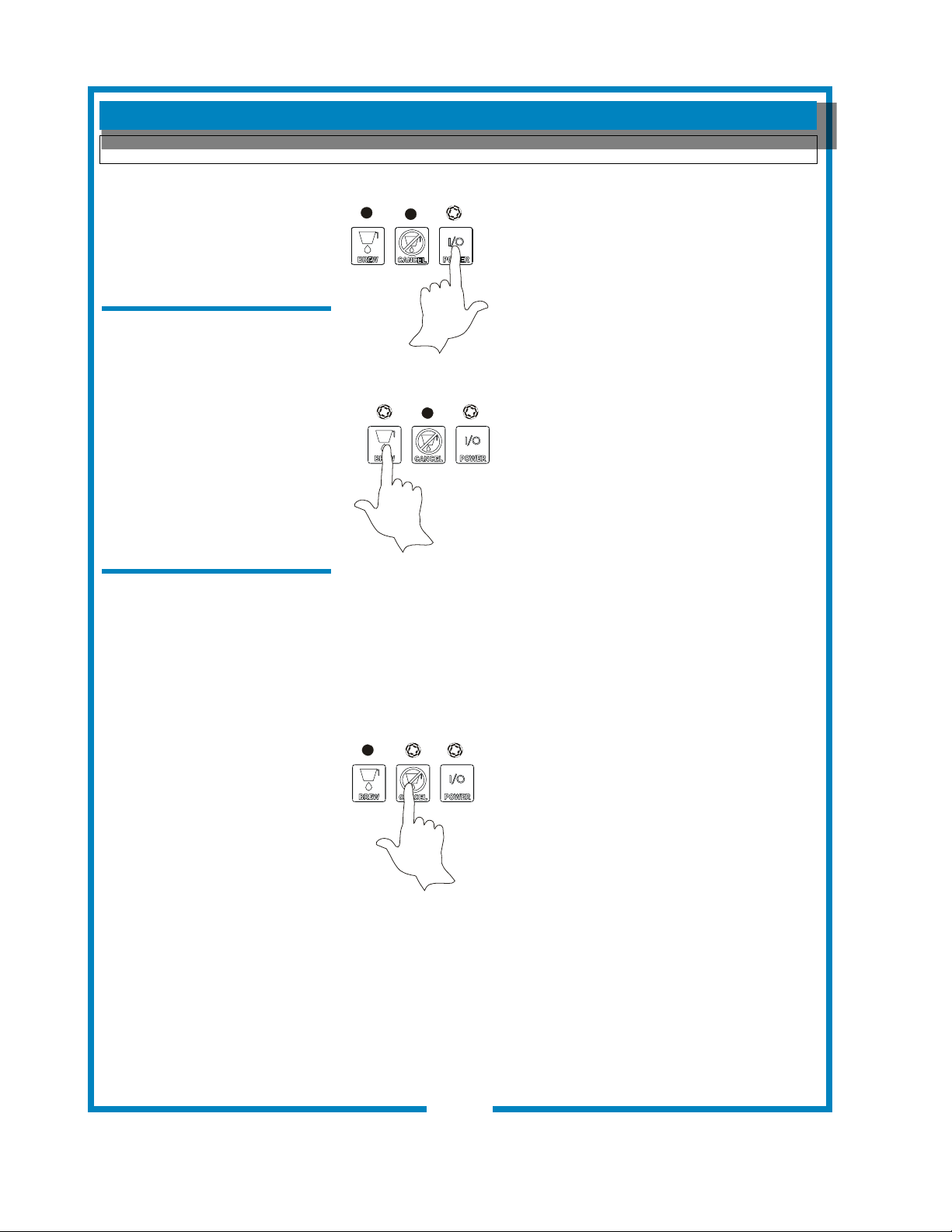
1. Energizing the Brewer: When electricity has been connected
to the unit, there will be a momentary ash of the power light.
Turn the brewer on by pressing the POWER
key. The brewer will start to ll the tank. With
the proper water supply the tank should be
lled in about 2½ minutes. Once lled, the
heating element will come on until the proper
tank temperature has been reached, (which
will take about 20 minutes on 120-Volt models
IL2715
or about 12 minutes on 120/240 Volt models).
2. Brewing (Precise Temperature for Brewing — PTB): In
the regular operating mode, the E-Max T maintains the tank
temperature within +/- 1ºF of the brew
temperature. Normally this will mean that
a brew will be started as soon as the
BREW key is pressed. However, there
may be a slight delay if the BREW key is
pressed immediately after a brew has been
completed (notably on 120 volt models).
If the tank temperature is below the brew
IL2716
temperature, the brew will be delayed,
going into the “Brew Wait” mode, with the brew light ashing.
As soon as the correct temperature is reached the brew will
commence with the brew light on continuously during the brew.
When the brew begins the main warming station will be turned
on automatically (if it is not already on). During the brew cycle,
if the BREW key is pressed, it will be ignored. Only when the
brew is complete can another brew be started.
3. Brew Cancel: To cancel a brew in progress, press the
CANCEL KEY: two beeps will sound and the “Brew” light will
go out. Water owing to the brew chamber
will be stopped immediately, but if there is
already water in the brew chamber, it will take
a few moments before this drips through as
coffee.
IL2717
4. Normal Operation (Non Brewing): When the unit is not
brewing, the E-Max T maintains the water temperature at the
Precise Temperature for Brewing (PTB). The heating element
will cycle on and off automatically to maintain this temperature.
5. After Hours Mode: If no brew is detected for a pre-selected
length of time, the brewer will enter the After Hours mode.
Temperature will be allowed to drop to save energy. Pressing
the BREW KEY returns the brewer to normal operation.
655 2M-Z17970 Owners Manual E-Maxl Thermal Brewer
6
Page 9
USER’S GUIDE
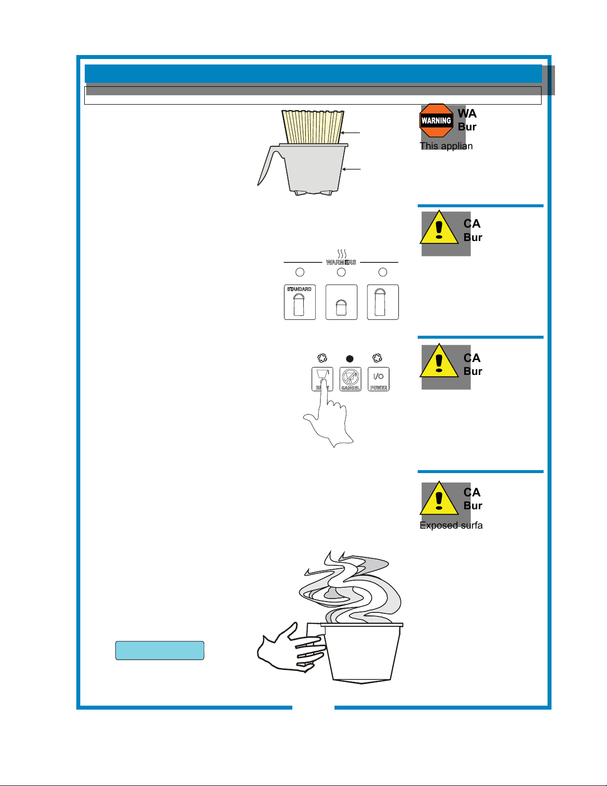
1. Remove the brew chamber from
under the spray head. Place one
(1) genuine Bloomeld paper
lter into the brew chamber.
Add your choice of measured
coffee grounds. Shake the
brew chamber gently to level
the grounds at. Slide the brew
chamber back into place.
2. Place an empty dispenser under the brew chamber.
3. If any volume other than “Standard”
brew volume is required, press the
appropriate volume key.
IL1605
PAPER
FILTER
BREW
CHAMBER
IL2722
OPERATING (continued)
WARNING:
Burn Hazard
This appliance dispenses
very hot liquid. Serious
bodily injury from scalding
can occur from contact with
dispensed liquids.
CAUTION:
Burn Hazard
To avoid splashing or
overowing hot liquids,
ALWAYS use an empty
dispenser before starting
the brew cycle. Failure to
comply can cause serious
burns.
4. To begin the brew cycle, press BREW
key. Hot water will start spraying over the
coffee grounds, and brewed coffee will start
lling the server. Cold water will ow from
the bypass valve to bring the coffee to the
proper concentration. When the coffee
stops owing from the brew chamber, the
fresh coffee is ready to serve.
NOTE: Brewing will not begin until the Precise Temperature for
Brewing has been reached. (See page 6)
5. At the end of the brew cycle,
the view screen will read “Brew
complete”. After all dripping
has stopped, remove the brew
chamber from the brewer. Discard
the used paper lter and coffee
grounds.
IL2716
CAUTION:
Burn Hazard
After a brew cycle, brew
chamber contents are HOT.
Remove the brew chamber
and dispose of used lter
and grounds with care.
Failure to comply can
cause serious burns.
CAUTION:
Burn Hazard
Exposed surfaces of the
appliance, as well as brew
chamber may be HOT to
the touch, and can cause
serious burns.
Brew complete
6. The brewer is now be ready to
begin another brewing cycle.
655 2M-Z17970 Owners Manual E-Maxl Thermal Brewer
IL2306
7
Page 10

OPERATION (continued)
PROGRAMMING FEATURES AND OPTIONS
1. View Water Temperature in Tank: To view the water temperature on the screen, E-Max T
brewer must be ON, and not brewing or in the lling mode. Press and hold the 4th key, and
depress the 6th key. The actual water temperature will be displayed for 3 seconds.
2. Daily Brew Count: The E-Max T maintains a count of the number of completed brews for a 7-day
period. To access the count, turn the brewer OFF. In the OFF mode, press and hold the CANCEL
key for 3 seconds. The current day and brew count will be displayed. Depress the ON/OFF key
repeatedly to view each preceding day. When all 7 days have been displayed a 7-day total will be
displayed. If you wish to exit the daily brew count before viewing all of the days, press CANCEL
key.
3. ON/OFF – Non Automatic Timer: To turn the brewer OFF, press the ON/OFF switch: 2 beeps will
be heard and the brewer will be turned OFF, indicated by all lights being off. To turn the brewer
ON, press the ON/OFF switch: 2 beeps will sound, all lights will ash once, then the “Power” light
will remain on, (the “Heat” light may come on if water temperature is too low).
4. ON/OFF – Automatic Timer Feature: The factory programmed E-Max T has the automatic timer
turned off. To set the automatic timer, refer to the E-Max Programming Manual, “Time Functions”
Menu. If the Automatic Timer feature is programmed off, the brewer can be turned on and off by
depressing the ON/OFF switch, as noted above.
* When the Automatic Timer feature is programmed ON, the E-Max T will turn on and off automatically, at a
programmed time, Monday to Friday; with a separate on and off programmed time schedule for Saturday
and Sunday.
* Temporarily Overriding the Automatic ON/OFF function. While in the automatic timed OFF mode the
brewer can be started by depressing the ON/OFF switch. The brewer will remain ON until the automatic
programmed off time, when it will turn OFF and resume normal automatic timed functioning. Similarly, if
turned OFF during the automatic timed ON mode the brewer will remain OFF until the next programmed
on time, when it will turn on and resume normal automatic timed functioning.
5. Automatic Start-Up in Previous Mode: If the E-Max T automatic timer is OFF (the factory
setting) and power is disconnected, the brewer will start up when power is restored, in the mode
it had been in prior to the power disconnection. If the E-Max has the timer setting ON and power
is disconnected, the brewer will start up in the mode that it should be in at the time the power is
restored.
6. Viewing Programmed Brew Volume: The E-Max T can have up to 4 different brew volumes.
When a volume other than the standard, or rst brew volume, is selected, the E-Max will complete
that volume and then automatically reset to the standard, or rst brew volume. With the brewer
ON, press and hold the CANCEL key. The 1st, or standard, volume will be displayed for 3
seconds (i.e. Volume #1 3 G), and then the day and time will be displayed.
7. Changing Brew Volume: Press the required volume key. If a volume is programmed for that key,
the volume will be displayed on the screen for 3 seconds and the light above the key will be turned
on. If no volume is programmed, the previous light will remain on and the screen will read “no
volume prog” (i.e. no volume programmed). When a brew volume other than the 1st, or standard
brew volume is selected, the E-Max T will complete the brew then return to the 1st or standard
brew volume automatically.
a. With Volume Keys: Brewers with 3 volume keys can change brew volumes as outlined
above
b. Without Volume Keys. For Brewers without volume keys, only one brew volume is
normally programmed. To change the brew volume refer to E-Max Programming Manual.
655 2M-Z17970 Owners Manual E-Maxl Thermal Brewer
10
Page 11

OPERATING (continued)
8. Clock
A. Time – Battery Backup. The E-Max T has a battery backup system which will maintain the proper
time during power failures, or when the brewer is unplugged (even for very prolonged periods of time).
Normally there will not be a need to set the time except for Daylight Saving Time changes, or moving the
brewer to different time zones.
B. Changing Day and Time: To change time, turn the E-Max T off. Press the 2nd key twice followed by
the 1st key twice to access the time change mode, (i.e. press CANCEL, CANCEL, BREW, BREW). In
the time change mode the screen will read “Day:” followed by the current day setting. Use the 6th key
to advance the day, or the 5th key to reverse. When day has been properly set, press the 3rd key. The
screen will now read “Time:” with the set time on the screen, the hour and am or pm ashing. Use the
5th key to go back or the 6th key to advance the hour, making sure that the am or pm is correct. When
the hour and am/pm is correctly set, press the 3rd key, and the screen will read “Time:” with the set time
on the screen, minutes ashing. As previously use the 5th or 6th keys to adjust the minutes, and press
the 3rd key when complete. E-Max T will return to the off mode. (Changing time can also be done in the
regular programming mode. Consult the E-Max Programming Manual)
C. After Hours: Consult the E-Max Programming Manual to set the After Hours mode. The factory
programming has the After Hours mode turned OFF. The After Hours can be programmed to come on
from 1 to 6 hours after the last brew. When the E-Max T goes into the After Hours mode, the water in the
tank will be allowed to drop from the normal brewing temperature and will reheat less frequently – this
feature saves energy and extend component life. While in the After Hours mode, the power light will
ash continuously. When the BREW switch is pressed the E-Max T automatically reverts back to normal
operation, heating the water to the Precise Temperature for Brewing (PTB), before starting the brew.
(The power light will be on continuously and the Brew light will ash until the correct water temperature is
reached.)
9. Countdown Quality Timer: Refers to coffee warmers, not applicable for Thermal Brewers.
10. Pulse or Pre-Infusion Volume Options:
To set these features, refer to E-Max
Programming Manual, Brew Settings Menu. If
a particular brew volume has utilized the pulse
or pre-infusion option, that volume will be
displayed with an asterisk (*) after the volume.
As an example “Volume#2 3 G*” would
indicate that the second programmed brew
volume has utilized the pulse or pre-infusion
program options.
11. Keypadlock: This feature is OFF in the
standard factory settings. To set the feature
refer to E-Max Programming Manual, Machine
Type: Satellite
Total Valve
Press 4th Key
Init. Valve Time 30
Pulse Delay 5
Pulse Valve On 10 25
Bypass Tiem 150 20 200
Brew Complete 45 30 60
Settings Menu. If the Keypadlock feature is
activated, there will be no response by the
brewer when the keys are depressed (except
To determine brew time for a volume divide ounces by
for the beep after a key is depressed). To
temporarily “unlock” the keypad, press and
hold the CANCEL key for 6 seconds. A beep
will be heard indicating the keypad is now
“unlocked”, — a brew can be initiated, warmer
plates turned on or off, etc. The keypad will remain unlocked until the brew is completed, then
automatically return to keypadlock mode. If a brew is not initiated 60 seconds after “unlocking”, the
system will time out and return to the “locked” position.
DEFAULT PROGRAMS
Position
1 Gal 1/2 Gal 1-1/2 Gal
215 142 322
Approximate Flow Rates
ow rate:
Brew Valve: .50oz sec
Bypass Valve .27oz sec
655 2M-Z17970 Owners Manual E-Maxl Thermal Brewer
11
Page 12

OPERATING INSTRUCTIONS (continued)
12. View Filter Statistics: To view lter statistics, turn the brewer off. Press and hold the 1st key
(Brew), and depress the 3rd (ON/OFF) key. Total water volume will be displayed (TotalVol.).
Press the 3rd key to view the Filter Life (FltrLife:). Press the 3rd key to view the percentage of the
lter that has been used. (If the lter option is used, the lter life volume needs to be entered in
the program – see E-Max Programming Manual, Service & Counters Menu.)
13. Diagnostic Messages – Programmed Safety Features: When E-Max T senses a problem, it
will automatically turn off all elements and valves, ash lights, display the message “Call For
Service” and display one of the messages below. (Additionally: a service phone number may
appear if it has been programmed into the system.)
* To reset the brewer it can be re-energized (or press and hold CANCEL for 3 seconds for all faults
except the Valve Fault, which must be reset by re-energizing). The brewer will try to re-start, but if the
same problem persists, the appropriate error message will appear again. Consult the Trouble Shooting
section to determine how to solve the problem.
A. “Probe/Heater Error”: Overheating Detection (1): If the heating element is on for 5 minutes and the
temperature does not change by +2°F (1°C) in the ve minute period, the unit will go into the Over Temperature Mode with all lights ashing. When in this mode the brewer turns off the heating elements, the
solenoid valves are turned off; the switches disabled; (and all lights ashing continuously). The LCD display will read “Probe/Heater Error”, followed by the message “Call for Service”, and then the service
phone number (if it has been entered into memory). To reset press and hold CANCEL for 3 seconds, or
re-energize the brewer. (Possible causes of problem: high limit needs to be re-set; defective high limit,
element, triac, water level probe or control board.)
B. “Overheat Error”: Overheating Detection (2): If the E-Max senses a temperature over the Maximum
Temperature set in the program (factory set at 208ºF or 98ºC) it will go into the over temperature mode
as above with all lights ashing, except the LCD will read “overheat error”, and “Call for Service”. To
reset press and hold CANCEL for 3 seconds, or re-energize the brewer. (Possible cause of problem is a
defective triac, temperature probe or related wiring and connections.)
C. “No Water Sensed” — Time-Out —Inlet Valve: When lling for the rst time, the inlet valve will remain
open for 4¼ minutes, (the screen will read “lling…”). If water is not detected at the end of this time
the E-Max will shut down with the message “no water sensed”. The valves and all elements are turned
off, and the Brew and Power light ash alternately with the Heat light, until the brewer is reset. To reset
press and hold CANCEL for 3 seconds, or re-energize the brewer. (Possible causes of the problem are:
no incoming water; slow ow of incoming water (i.e. less than 45 oz/minute); sensor not reading (check
for placement, connections or lime scale).
D. “No Water Sensed” — Time-Out – Brew Valve: During the brew the inlet solenoid valve cycles on
intermittently to maintain the proper level in the tank. If the valve is open for 60 seconds without water
being detected at the proper level, the brewer will go into the same error mode as above (“no water
sensed”). To reset press and hold CANCEL for 3 seconds, or re-energize the brewer. (Possible causes
of the problem are: no incoming water; slow ow of incoming water, sensor not reading, etc.).
E. Keyswitch Locked: If a key switch is depressed for 10 seconds this error message will occur. Lights
will ash alternately and the brewer will turn off all valves and elements. Press and hold the CANCEL
key for 3 seconds to reset the brewer (or re-energize the brewer). If the problem re-occurs this indicates
a defective switch on the key pad.
F. “Valve Fault”- Faulty Valve Detection: When an electric or switching problem is detected with either
the inlet or brew valve the brewer turns off all elements and valves and displays “valve fault…”. All of
the lights will be turned on. Before re-setting the brewer the valves must be checked to determine the
problem. The brewer must be re-energized to re-set, (pressing CANCEL for 3 seconds will not reset a
valve fault).
655 2M-Z17970 Owners Manual E-Maxl Thermal Brewer
12
Page 13

WATER FLOW
IL2307
BREW
HEAD
BYPASS
NOZZLE
BREW
VALVE
VENT (TO BREW HEAD)
WATER LEVEL PROBE
TEE
HOT
WATER
TANK
INLET
VALVE
HOT WATER
COLD WATER
HOT WATER
FAUCET
BREW
CHAMBER
W/BYPASS
CHANNEL
OPERATING INSTRUCTIONS (continued)
INLET
The INLET VALVE is controlled by a signal from the CONTROL
BOARD. If the WATER LEVEL PROBE does not detect water, the inlet
solenoid is opened until water is again sensed.
BREW AND BYPASS
The BREW VALVE fed by gravity from the hot water tank. The brew
valve is opened for a length of time as determined by the CONTROL
setting. The brew valve discharged through the BREW HEAD:
• A portion of water is fed to the BYPASS through a reducing “tee”.
The amount of bypass water is PRESET @ approx. .27oz per
second. Bypass water ows through the brew basket, but
is diverted from the grounds by a bypass channel.
• The remainder of the water is discharged through the BREW HEAD
and ows over the grounds in the brew basket at a PRESET of
approx. .50 oz per second.
HOT WATER FAUCET
The HOT WATER FAUCET is fed by gravity from the hot water tank.
The faucet is spring-loaded closed and manually opened.
655 2M-Z17970 Owners Manual E-Maxl Thermal Brewer
13
The hot water faucet is fed
by the hot water tank, but
is otherwise independent of
the brewing systems.
NOTE:
Use of the hot water faucet
during a brew cycle will
not change the delivered
volume. However,
excessive use of the faucet
during brew may lower the
brew water temperature.
Page 14

CLEANING INSTRUCTIONS
IL2724
CLEANING INSTRUCTIONS
CAUTION:
BURN HAZARD
Brewing and serving
temperatures of coffee are
extremely hot.
Hot coffee will cause serious
skin burns.
IMPORTANT:
DO NOT use steel wool, sharp
objects, or caustic, abrasive or
chlorinated cleansers to clean
the brewer, brew baskets or
servers.
DO NOT immerse or submerge
satellites in water.
BREW
HEAD
SPOUT
INSERT
SPRAY HEAD
GASKET
SPRAY
DISK
LIFT EARS UP
TURN LEFT
TO REMOVE
PROCEDURE: Clean Coffee Brewer
PRECAUTIONS: Press POWER key to OFF.
Allow brewer to cool.
FREQUENCY: Daily
TOOLS: Mild Detergent, Clean Soft Cloth or Sponge
Bristle Brush
1. Disconnect brewer from electric power.
Allow brewer to cool.
2. Remove servers.
3. Remove and empty brew baskets.
4. Remove spray disks and gaskets from spray heads
5. Wipe inside of spray head and area around spray head with a
soft clean cloth or sponge moistened with clean water.
6. Wash spray disks in a sink using warm water and a mild
detergent. A bristle brush may be used to clear clogged
spray holes. Rinse spray disks with clean water and allow to
air dry.
7. Wash brew baskets in a sink using warm water and a mild
detergent. A bristle brush may be used to clean around the
bypass diverters. Rinse with clean water and allow to air dry.
Be sure bypass diverters are properly installed.
8. Wipe exterior of brewer and servers with a soft clean cloth or
sponge moistened with clean water.
9. Reinstall gaskets INSIDE brew heads, and then reinstall
spray disks.
10. Reinstall brew chambers.
11. Reinstall servers.
Procedure is complete
655 2M-Z17970 Owners Manual E-Maxl Thermal Brewer
10
Page 15

CLEANING INSTRUCTIONS (continued)
PROCEDURE: Clean Thermals
PRECAUTIONS: Drain Thermal before Cleaning
FREQUENCY: Daily
TOOLS: Sanitizer, Soft Clean Cloth, Bucket
1. Remove and drain thermals. Remove lids.
2. Remove funnel assembly and clean with mild detergent and
warm water.
3. Fill Server 1/4 to 1/2 full with hot water, (use a non-caustic
cleaning solution if appropriate).
4. Use a brush to clean the inside of the server.
5. Drain server, rinse & dry the outside surfaces with dry cloth.
6. Reinstall funnel assembly, lids & drip tray. Install satellites
on brewer.
7. Rinse servers: with an empty brew chamber in place, press
the BREW key and run 1 full cycle into each server.
8. Drain water from server.
Procedure is complete
CAUTION:
BURN HAZARD
Brewing and serving
temperatures of coffee
are extremely hot.
Hot coffee will cause
serious skin burns.
IMPORTANT:
DO NOT submerge thermals in
water.
IMPORTANT:
DO NOT use steel wool, sharp
objects, or caustic, abrasive or
chlorinated cleansers to clean
the servers.
655 2M-Z17970 Owners Manual E-Maxl Thermal Brewer
11
Page 16

SERVICING INSTRUCTIONS
CAUTION:
CHEMICAL BURN
HAZARD
Deliming chemicals may be
caustic. Wear appropriate
protective gloves and goggles
during this procedure. Never
siphon deliming chemicals or
solutions by mouth.
This operation should only be
performed by qualied and
experienced service personnel.
IMPORTANT: DO NOT spill,
splash or pour water or deliming
solution into or over any internal
component other than the inside
of the water tank.
IMPORTANT: DO NOT allow
any internal components to
come into contact with the
deliming solution. Take care to
keep all internal components
dry.
NOTE: Repeat steps 4 and 7
as required to remove all
build-up.
PROCEDURE: Delime the Water Tank
PRECAUTIONS: Disconnect brewer from electric power.
Allow brewer to cool.
FREQUENCY: As required (Brewer slow to heat)
TOOLS: Deliming Solution
Protective Gloves, Goggles & Apron
Mild Detergent, Clean Soft Cloth or Sponge
Bristle Brush, Bottle Brush
Large Sink (or other appropriate work area)
1. Disconnect brewer from the electrical supply.
2. Remove the brewer top panel, then remove the tank lid
assembly. Do not disconnect the tank assembly at this
time.
3. Drain all water from the hot water tank
(see DRAINING HOT WATER TANK procedures).
4. Mix 10 gallons of deliming solution according to the
manufacturer’s directions. Carefully pour the deliming
solution into the water tank. Lower the lid assembly back
onto the tank. Allow to sit for 30 minutes, or as directed by
the chemical manufacturer.
5. At end of soaking period, reconnect brewer to electrical
power. Install the brew chamber without lter paper or
grounds. Place an empty server under the brew chamber.
Force a 1-1/2 gallon brew:
a. Press the 1-1/2 gallon key
b. Press the brew key, then press and hold the brew key
until a brew is initiated.
Empty the server and repeat for the other side.
655 2M-Z17970 Owners Manual E-Maxl Thermal Brewer
6. Disconnect brewer from electrical power and allow to cool.
7. Remove lid assembly from tank.
a. Using a stiff bristle brush, scrub internal components to
remove lime and calcium build-up.
b. Thoroughly rinse internal components of lid assembly
with clear water.
c. Store lid assembly in a safe location.
8. Using a stiff bristle brush, scrub exposed portions of the
heating element and the inside surfaces of the tank to
remove lime and calcium build-up.
9. Siphon all solution from the tank.
12
Page 17

SERVICING INSTRUCTIONS (continued)
10. Reinstall tank lid assembly into hot water tank. Make sure
the lid gasket is properly in place, then reinstall the
hold-down clamps.
11. Remove spray disks and gaskets. Rinse both brew heads
with clean water. Using a stiff brush, scrub spray disk to
remove any lime or calcium build-up. Inspect gaskets and
replace if it shows any loss of plasticity, reinstall gaskets
and spray disks.
13. Reconnect brewer to electrical supply .
14. Install the brew chamber without lter paper or grounds.
15. Place an empty server under the brew chamber. Run at
least ve 1-1/2 gallon brew cycles and discard all water
generated at the end of each cycle.
Repeat for the other side.
16. Rinse server with clean water. Reinstall one empty
satellite under each brew chamber.
Brewer is ready to use.
DRAINING HOT WATER TANK
1. Disconnect brewer from the electrical supply
2. Remove the top panel assembly (4 Screws)
3. Remove the front panel assyembly (4 Screws)
4. Release the drain hose & hose clamp assy from the retaining
clip.
5. Bring the drain hose down out the front panel so its lower
than the tank.
6. Remove the red hose cap.
6. Open the hose clamp and drain into container.
CAUTION: Tank holds 6 gallons of water and can may contain
HOT WATER,
7. When tank is empty, close the hose clamp and place the red
cap back into position.
8. Place the end of the hose back into its retaining clip.
NOTE: Normally, silicone
hoses do not need to be
delimed. Should deliming hoses
become necessary, Bloomeld
recommends replacing the
hoses.
IMPORTANT: DO NOT allow
any internal components to
come into contact with the any
deliming solution. Take care to
keep all internal components
dry.
655 2M-Z17970 Owners Manual E-Maxl Thermal Brewer
13
Page 18

NOTES
18
655 2M-Z17970 Owners Manual E-Maxl Thermal Brewer
Page 19

TROUBLESHOOTING SUGGESTIONS
If the E-Max T goes into the error mode as outlined below, it will likely be necessary to reset the brewer
in order to test individual components. Note the reset procedure below:
• For the rst four error modes, press and hold CANCEL for 3 seconds, or RE-ENERGIZE the brewer
by disconnecting from electric power for 5 seconds, then reconnecting.
• From “VALVE FAULT”, the brewer must be RE-ENERGIZED! Using the CANCEL button will not
reset the brewer from “Valve Fault”.
The Test Program will also assist in isolating and testing specic components. As an example to test
the three main components in the heater system, go to the test program and proceed to turn the “heater
on”. Use a meter or test light to determine if power is getting to and from: the triac, the high limit and the
element.
ERROR
MESSAGE CAUSE SUGGESTIONS FOR REMEDIAL ACTION
“Probe/Heater”
1
Error RESET
by holding
CANCEL switch
for 3 seconds
“Overheat” Error
2
RESET by
holding
CANCEL switch
for 3 seconds
“No Water
3
Sensed” Error
RESET
by holding
CANCEL switch
for 3 seconds
Controller has turned
heating element
on for 5 minutes
without sensing a
+2ºF change in water
temperature.
Water temperature
has exceeded
Maximum Water
Temperature
programmed into
“Machine Settings”
menu.
Inlet valve energized
but no water is
sensed during
regular operation for
60 seconds; or. no
water sensed during
start-up (manual
or timed) for 4½
minutes.
1
Temp Probe may not be connected properly, or may be defective. CHECK & CORRECT. To test
probe, go to Test Program and view probe value. A value of over 155 indicates a defective probe; a
value of under 15 indicates a bad connection of the probe to the board. With an ohmmeter measure
resistance of probe. At 212ºF, resistance is approx. 2,000W If less than 1800W at room temperature
probe is defective.
May be boiling due to high altitude (boiling point below Brew Temp.) or Triac has failed ON and hi-limit
2
has interrupted power to heating element. REDUCE BREW TEMP. CHECK TRIAC; REPLACE IF
DEFECTIVE.
Heating element defective. CHECK ELEMENT; replace if defective.
3
Hi-limit thermostat may be cutting out at too low a temperature. CHECK HI- LIMIT THERMOSTAT;
4
REPLACE IF DEFECTIVE. (Note; hi-limit will reset itself if allowed to cool by 30ºF, making
troubleshooting a challenge as the brewer cools then functions normally.)
Heating element may be encrusted with lime or scale build-up. DELIME BREWER AS DETAILED ON
5
PAGE 16.
1
Brew Temperature may be set too close to Maximum Temperature. Brew Temperature should be at
least 5ºF below Maximum Water Temperature.
LOWER BREW TEMPERATURE or RAISE MAXIMUM TEMPERATURE
(Software versions after May, 1999 enforce the 5ºF differential)
Triac has failed ON; element continues to heat even when controller is OFF. CHECK TRIAC;
2
REPLACE IF DEFECTIVE.
Temp Probe defective. See probe test procedure in Item #1 above. CHECK PROBE; REPLACE IF
3
DEFECTIVE.
Sleeve on water level sensor is too long, or sensor is not pushed down fully. Sensor should extend
beyond sleeve a minimum of ¼” to a maximum of l”. REMOVE TANK LID, CUT SLEEVE TO PROPER
1
LENGTH. ENSURE SENSOR IS PUSHED DOWN ALL THE WAY.
Wiring to water level sensor disconnected or defective; or, sensor pulled out of tank. CHECK &
2
CORRECT.
Water level sensor may be encrusted with lime build-up. CLEAN SENSOR.
3
Water supply may be OFF. CHECK & RESTORE WATER SUPPLY.
4
Keyswitch
4
Locked” Error
RESET as
above
Valve Fault”
5
Error RESET by
disconnecting/
reconnecting
electric power
655 2M-Z17970 Owners Manual E-Maxl Thermal Brewer
A switch on the
keypad has been
held down for more
than 10 seconds.
Detection of a
problem with the
valve switching
system, or with the
wiring to the valves.
Switch has been accidentally held for 10 or more seconds. RELEASE SWITCH
1
Defective keypad. PRESS & HOLD “CANCEL” FOR 3 SECONDS. Observe brewer to determine if
2
problem persists. (Note: available on software versions MFW 275 Rev. 3.4 and later versions only).
Wiring to either inlet or outlet valve not properly connected. CHECK WIRING AND CONNECTIONS.
1
The controller has two switches for each valve and one or both has been detected as failing ON.
(This prevents the brewer from operating unless both switches are working properly.) REPLACE
2
CONTROLLER.
19
Page 20

E-Max TTM TEST PROGRAM
Remember: Exiting Test
Program Mode:
To exit the Test Program, press
the 2nd key (Cancel) at any
time, except during the key
switch tests below. Alternately,
complete the full test and the
E-Max T will return to the OFF
mode.
Note: each key press should
be followed by an audible
beep.
Note: Bloomeld
recommends that, should
the keypad fail a test, the
test be carefully repeated at
least three times to verify the
keypad failure.
Instructions for testing procedures for the following system
components (using the E-Max T Built-In Diagnostic):
Electronic Board Software (Firmware) Revision
Keypad switches
LED’s
Inlet valve, Dump (Brew) valve, By Pass Valve
Water level probe, Temperature probe
A. Entering Test Program Mode:
1. Make sure to have power to the system. Press the 3rd key to enter
the OFF mode.
2. In the Off mode, hold down the 3rd (ON/OFF) and 4th keys
(1st volume key or “E” in “E-Max T”). Hold both keys down for
approximately 3 seconds.
If successful, a message containing the revision of the rmware will
be displayed: (e.g. “MFW275T Rev 1.2”)
3. Press the 3rd key.
B. Check Data Revision
1. The next display contains the revision number of the data
programmed into the EEPROM: (e.g. “Data Rev1.2”).
2. Press the 3rd key to continue.
C. Time
Time is preset
D. Switch Test - The keys are tested in this stage.
1. Test 1st key by pressing the “BREW” key. Y u will hear a beep, and
the display will change to “Test Switch 2”.
2. Test 2nd key by pressing the “CANCEL” key. You will hear a beep,
and the display will change to “Test Switch 3”
3. Test the 3rd key by pressing the “ON/OFF” key. You will hear a
beep, and the display will change to “Test Switch 4”
4. Continue by pressing the 4th key (1st volume key, or “E” in
“E-Max T’);
5. 5th key (2nd volume key, or “a” in “E-Max T”); and,
6. 6th key (3rd volume key, or “T” in “E-Max T”)
Except for Switch 1, if a key press is not detected within ve
seconds, the “Switch Error” message Will be displayed followed by
two beeps. For Switch 1, the time limit is 30 seconds.
If an error occurs when the correct key is pressed, the keypad has
failed the test.
655 2M-Z17970 Owners Manual E-Maxl Thermal Brewer
20
Page 21

E-Max TTM TEST PROGRAM
E. LED Test The display should read “Testing LED’s”:
Individual LED’s will be tested individually, beginning with the rst
on the left, and proceeding through all six LED’s at one-second
intervals. Screen will read “Testing LED’s” during the entire test.
1. Verify that only one LED at a time is lit, and that each of the six LED’s
light in their proper sequence.
L1 L2 L3 L4 L5 L6
BREW CANCEL ON/OFF Volume 1 Volume 2 Volume 3
or “E” or “a” or “T”
2. Verify that each LED is the correct RED color:
3. When all lights have been tested, press the 3rd key (ON/OFF) to
continue.
F. Output Test The valves and heater are tested in this stage.
Display should read “Inlet 1 Off”:
1. Press the 3rd key. The inlet valve should turn on, and the display
should read “Inlet 1 ON”
2. Continue pressing the 3rd key, in sequence, to advance through the
component tests, Each component should turn ON then OFF in the
following order:
Output 1 Inlet
Output 2 Dump
Output 3 Heater
Output 4 Bypass
Output 5 (Future - not functional at this time)
Output 6 (Future - not functional at this time)
3. Each component should turn ON in order, with only one component
ON at a time. If the components fail to turn on in the proper
sequence, or if a “Valve Fault” message is displayed, the controller
has failed the test.
G. Probes Test This section ensures the proper functioning of the
Water Level Probe and Temperature Probe:
1. The left number determines whether the WATER-sensing probe is in
contact with water.
a. A number of “0” (or close to 0) means that water is in contact with the
probe.
b. A number of 255 (or close to 255) means water is not in contact with
the probe.
2. The right number represents what the reads. The table at right is an
approximate correlation between the value and the temperature the
probe is sensing. (Note a number less than 10 would indicate the
probe is not properly connected to the board, while a number higher
than 155 indicate a defective probe.)
H. Test Done. Indicates completion, press ON/OFF to reset
controller. The controller should restart with the message
“BLOOMFIELD”, then return to the OFF mode.
655 2M-Z17970 Owners Manual E-Maxl Thermal Brewer
21
Page 22

SK2731, Rev. - 12/23/13
Model: 2795TF
E-Max Thermal Brewer
1
2
34
5
8
9
10
30
11
12
13
14
16
17
18
20
24
25
1
27
28
29
26
1
SEE DETAIL
A
21
22
23
19
15
6
3
7
EXPLODED VIEW ; 2795TF CABINET AND EXTERIOR COMPONENTS
655 2M-Z17970 Owners Manual E-Maxl Thermal Brewer
18
Page 23

PARTS LIST ; 2795TF CABINET AND EXTERIOR COMPONENTS
Model: 2795 E-Max Thermals Brewer
Fig No. Parts List Qty Description Application
1 2C-6349 12 SCREW #8X3/8 B THP STL NP
2 D7-Z16539 1 TOP COVER
3 2V-73388 2 VALVE ADJ. WATER OUTLET
4 D7-Z17807 1 BRACKET, BYPASS
6 D7-76576 1 BRKT OUTLET VALVE
7 2K-73152 1 ELBOW SPRAYER 1/4 ID
8 D7-Z16740 1 BRKT BOARD MTG RIGHT EMAX
9 D7-Z16739 1 BRKT BOARD MTG LEFT EMAX
10 2E-Z17751 1 BOARD SET, CONTROL
11 2G-73571 1 INSERT SPRAY HEAD SS2
12 2I-72215 1 GASKET SPRAY HEAD 1.5 ID
13 A6-72727 1 SPRAY HEAD DISC EMBOSSED
14 D7-76652 1 CHAMBER BREW ASSY
15 D7-Z16812 1 BRKT BYPASS PLASTIC BREW
16 2U-71061 1 FAUCET HOT WATER
17 2E-37465 1 TERM BLOCK 3POLE 85AMP
18 D7-Z17065 1 BRKT- TERMINAL BLOCK
19 2C-Z2594 2 NUT 6-32 HEX W STL NP
20 2A-73098 4 LEG 4 BLK PLASTIC W/FLAN
21
22 2V-74427 1 SOLENOID SINGLE 120V 1.0
23 2Q-75089 1 DOOR ACCESS PLASTIC
27 Z1-70-07-0343 1 SWITCH GUARD
28 2E-30330 1 SWITCH ON OFF TOGGLE 20A
29 2E-33192 1 PANEL ON & OFF SWITCH
30 2M-Z17916 1 KEYPAD SINGLE - THERMAL
NI 2A-76574 1 TUBE BYPASS
NI
NI A6-73537 3 TUBE SIL .312 ID X 9 LG
NI D7-Z16477 1 TUBE SILICONE .312 X 41.5
NI D7-Z17081 1 TUBE, SIL .500 ID 8.5
2K-300102
2K-76118 STRAIN RELIEF 120V
2M-Z17591
2M-Z19069 120V
STRAIN RELIEF 1NPT.375-1. 240V
1
1 DIAGRAM WIRE LABEL
240V
655 2M-Z17970 Owners Manual E-Maxl Thermal Brewer
August 05, 2014, Rev C
19
Page 24

EXPLODED VIEW ; 2795TF INTERIOR COMPONENTS
7
17
16
18
15
19
20
13
14
22
10
11
12
6
8
9
1
2
3
4
5
655 2M-Z17970 Owners Manual E-Maxl Thermal Brewer
Model: 2795TF
E-Max Thermal Brewer: Tank Assy
21
DETAIL A
SK2732, Rev. - 12/23/13
20
Page 25

PARTS LIST: 2795TF INTERIOR COMPONENTS
Detail A: 2795 Tank Assy
Fig No Part No. Qty Description Application
1 D7-73414 1 SHIELD HI-LIMIT
2 2C-73415 2 NUT 6-32 HEX 1.00 LG ALUM
3 2T-73312 1 THERMO HI LIMIT DBL POLE
4 D7-WL0347 1 TANK COVER ASSY
5 2N-76571UL
6 2J-73644 1 PROBE TEMPERATURE 5 1/2
7 2A-74343 1 TUBE FILL 90 DEGREE
8 2I-72390 1 GROMMET .375 ID TRANSLUCE
9 2K-70103 2 ELBOW OUTLET
10 2A-73384 3 TUBE SPRAY HEAD 2 3/8 LG
11 A6-73521 1 PROBE ASSY WATER LEVEL
12 2A-73532 1 SLEEVE WATER LEVEL PROBE
13 2I-Z16545 1 TANK GASKET
14 D7-WL0346 1 TANK WELDMENT
15 2C-43914 1 TIE WIRE MTG STUD M4200-2
16 D7-Z16559 1 BRACKET, TANK TOP
17 2C-6349 2 SCREW #8X3/8 B THP STL NP
18 2C-35485 2 NUT 1/4-20 HEX FINISHED S
19 2P-306831 1 CAP PLUG PLASTIC .5 DIA.
20 F4-73977 1 TUBE SIL .312 ID X 35
21 D7-Z16537 1 TANK SUPPORT BOTTOM
22 2K-Y5093 3 BUSHING-SNAP #SB-1000-12
NI 2C-76564 1 CLAMP HOSE SHUT OFF
2
ELEM HEATIN 120V 1500W HW
1 120V
240V
655 2M-Z17970 Owners Manual E-Maxl Thermal Brewer
August 05, 2014, Rev C
21
Page 26

WIRING DIAGRAM
10
HEATING
ELEMENT
120V 1500W
5
1
2
LEFT
13
16
WARMER
ELEMENT
2121 ONLY
5
13
14
4
3
17
HEATING
ELEMENT
120V 1500W
12
HI-LIMIT
THERMOSTAT
1
2
POWER
SWITCH
15
18
18
RIGHT
6
8
1
BYPASS
VALVE
8
INLET
VALVE
9
2
DUMP
VALVE
7
7
3
TRIAC
10
1 WP3
2 WP2
3 WP1
4
14
4
17
19
3
4
3
1
2
6
9
11
16
15
19
3
4
MODEL:
2795
2121
VOLTS:
120/240V 3050
120/240V
PHASE:
1
1
WATTS:
3150
11
8
1 HEATER (LINE)
2 INLET (LINE)
3 DUMP (LINE)
4 POWER (HOT)
6 DUMP (NEUT)
7 POWER (NEUT)
8 INLET (NEUT)
655 2M-Z17970 Owners Manual E-Maxl Thermal Brewer
2M-Z17591
WARMER SWITCH
2121 ONLY
1
HI-LIMIT
THERMOSTAT
2
26
Page 27

WIRING DIAGRAM
Load
Line
Gate
CONTROL BOARD
1 WP3
2 WP2
3 WP3
1 HEATER (LINE)
2 INLET (LINE)
3 DUMP (LINE)
4 POWER (HOT)
6 DUMP (NEUT)
7 POWER (NEUT)
8 INLET (NEUT)
1
1650
120V
2121
120V
1550
MODEL:
VOLTS:
WATTS:
2795
PHASE:
1
B WG B WG
1
2
3
4
1
2
3
4
HI-LIMIT
THERMOSTAT
HI-LIMIT
THERMOSTAT
TRIAC
WARMER SWITCH
2121 ONLY
WARMER
ELEMENT
2121
ONLY
HEATING
ELEMENT
120V 1500W
BYPASS
VALVE
INLET
VALVE
DUMP
VALVE
POWER
SWITCH
1
2
4
3
1
2
3
4
4
1
3
2
5
5
6
6
7
7
8
8
8
9
9
10
10
11
11
13
13
14
14
15
15
16
16
17
17
18
18
19
19
2M-Z19069 REV A
4
5
G A1
A2
655 2M-Z17970 Owners Manual E-Maxl Thermal Brewer
27
Page 28

10 Sunnen Drive, St. Louis, MO 63143
telephone: 314-678-6336 fax: 314-781-2714
www.bloomfieldworldwide.com
 Loading...