

Page 1
XCEL-50EC
HALF-SIZE ELECTRIC CONVECTION OVEN
INSTALLATION - OPERATION
BLODGETT OVEN COMPANY
www.blodgett.com
44 Lakeside Avenue, Burlington, Vermont 05401 USA Telephone: (802) 658-6600 Fax: (802)864-0183
PN 52137 Rev E (3/14)
© 2014 - G.S. Blodgett Corporation
Page 2
Your Service Agency’s Address:
Model
Serial number
Oven installed by
Installation checked by
Page 3

IMPORTANT
TABLE OF CONTENTS
WARNING: Improper installation, adjustment, alternation,
service or maintenance can
cause property damage, injury or death. Read the instllation, operation and maintenance instructions thoroughly
before installing or servicing
this equipment.
FOR YOUR SAFETY
Do not store or use gasoline or
other ammable vapors or liquids in the vicinity of this or any
other appliance.
The information contained in this
manual is important for the proper installation, use, and maintenance of this oven. Adherence
to these procedures and instructions will result in satisfactory
baking results and long, trouble
free service. Please read this
manual carefully and retain it for
future reference.
INSTALLATION
Oven Description and Specications .................................................................... 2
Oven Location ...................................................................................................... 3
Utility Connections ................................................................................................ 4
Delivery and Inspection ........................................................................................ 5
Oven Assembly..................................................................................................... 6
Oven Assembly to Stand ................................................................................ 6
Oven Leveling ................................................................................................ 6
Drain Assembly .............................................................................................. 7
Cleaning System Connection ......................................................................... 9
Water Connection .......................................................................................... 9
Misc Parts .................................................................................................... 10
Installing Drain Hose .................................................................................... 10
OPERATION
IQ Vision Control .................................................................................................11
Troubleshooting .................................................................................................. 13
ERRORS: Descriptive, typographic or pictorial errors are
subject to correction. Specications are subject to change without notice.
Page 4
Installation
Oven Description and Specications
Cooking in a convection oven differs from cooking in a
conventional deck or range oven since heated air is constantly recirculated over the product by a fan in an enclosed chamber. The moving air continually strips away
the layer of cool air surrounding the product, quickly allowing the heat to penetrate. The result is a high qual-
ity product, cooked at a lower temperature in a shorter
amount of time.
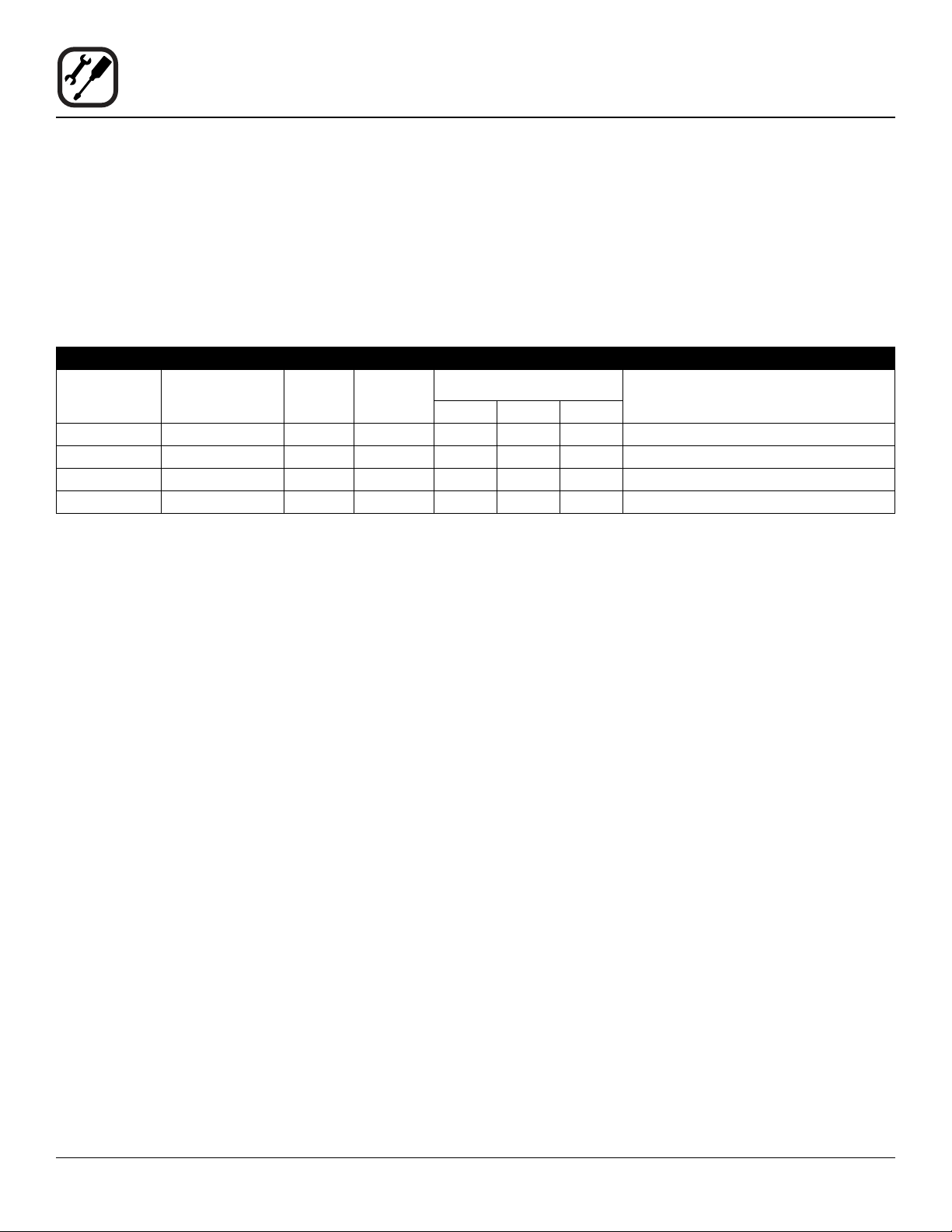
ELECTRICAL RATINGS- XCEL-50EC
VOLTAGE
208 60 13.0 3 38 38 34 8
240 60 13.0 3 34 34 30 8
208 60 13.0 1 63 63 — 2
240 60 13.0 1 55 55 — 2
NOTE: *Electric connection wiring is sized for good copper wire at 125% of rated input. Refer to this manual for electrical
connection specications.
NOTE: Double units can have phase loads partially equalized by matching lines during hook-up. Otherwise double unit load
ratings are twice the above data.
HZ
KW
PHASE
Blodgett convection ovens represent the latest advancement in energy efciency, reliability, and ease of operation. Heat normally lost, is recirculated within the cooking
chamber before being vented from the oven: resulting in
substantial reductions in energy consumption and enhanced oven performance.
MAX LOAD (AMPS) ELECTRICAL CONNECTION
L1 L2 L2
AWG*
2
Page 5

Installation
Oven Location
The well planned and proper placement of your oven will
result in long term operator convenience and satisfactory
performance.
The XCEL-50EC requires 0” (0 cm) clearances between
the oven sides and back and any combustible or noncombustible construction. However, we recommend that
adequate clearance be maintained for proper servicing.
Keep the oven area free and clear of all combustibles
such as paper, cardboard, and ammable liquids and solvents.
To ensure proper operation, ventilation must not be obstructed in any way. Tripping of the blower motor thermal
overload protective device is caused by excessive ambient temperature on the control side of the oven resulting
from insufcient ventilation. This condition must be corrected immediately to avoid permanent damage to the
oven.
Before making any utility connections to this oven, check
the rating plate to be sure the oven specications are
compatible with the electrical services supplied for the
oven.
1. Pull out control panel. The rating plate attached to the
inside of the control compartment.
ADJUSTMENTS ASSOCIATED WITH INITIAL
INSTALLATION
Each oven, and its component parts, have been thoroughly tested and inspected prior to shipment. However, it is
often necessary to further test or adjust the oven as part
of a normal and proper installation. These adjustments
are the responsibility of the installer, or dealer. Since
these adjustments are not considered defects in material or workmanship, they are not covered by the Original
Equipment Warranty. They include, but are not limited to:
• leveling
• tightening of fasteners.
No installation should be considered complete without
proper inspection, and if necessary, adjustment by qualied installation or service personnel.
3
Page 6
Installation
Utility Connections
THE INSTALLATION INSTRUCTIONS CONTAINED
HEREIN ARE FOR THE USE OF QUALIFIE0 INSTALLATION AN0 SERVICE PERSONNEL ONLY. INSTALLATION OR SERVICE BY OTHER THAN QUALIFIE0
PERSONNEL MAY RESULT IN DAMAGE TO THE OVEN
AND/OR INJURY TO THE OPERATOR.
Qualied installation personnel are individuals, a rm,
a corporation, or a company which either in person or
through a representative are engaged in, and responsible
for:
• the installation of electrical wiring from the electric
meter, main control box or service outlet to the electric appliance.
Qualied installation personnel must be experienced in
such work, familiar with all precautions required, and have
complied with all requirements of state or local authorities
having jurisdiction.
U.S. and Canadian installations
All ovens, when installed, must be electrically grounded
in accordance with local codes, or in the absence of local codes, with the National Electrical code, ANSI/NFPA
70-Latest Edition and/or Canadian National Electric code
C22.2 as applicable.
The ventilation of this oven should be in accordance with
local codes. In the absence of local codes, refer to the
National ventilation code titled, “Standard for the Installa-
tion of Equipment for the Removal of Smoke and Grease
Laden Vapors from commercial cooking Equipment”, NF-
PA-96-Latest Edition.
This equipment is to be installed in compliance with the
Basic Plumbing code of the Building Ofcials and code
Administrators International Inc. (BOCA) and the Food
Service Sanitation Manual of the Food and Drug Administration (FDA).
This product must be installed by a licensed Plumber or
Gas Fitter when installed within the Commonwealth of
Massachusetts.
Appliance is to be installed with backow prevention in
accordance with applicable federal, province and local
codes.
General export installations
Installation must conform with Local and National instal-
lation standards. Local installation codes and/or requirements may vary. If you have any questions regarding the
proper installation and/or operation of your Blodgett oven,
please contact your local distributor. If you do not have a
local distributor, please call the Blodgett Oven Company
at 0011-802-658-6600.
ELECTRICAL CONNECTION
WARNING!!
Before making any utility connections to this
oven, check the rating plate to be sure the
oven specications are compatible with the
electrical services supplied for the oven.
Wiring diagrams are located in the control compartment
area.
Ovens are supplied for operation in several voltage choices, single or three phase grounded circuits.
U.S. and Canadian Installations
The electric motor, indicator lights and related switches
are interconnected through the one power source supplied to the oven.
1. The supply conduit enters through the rear of the
oven and electrical block secured to the perforated
panel at the back of the control compartment.
General Export Installations
Export ovens are not supplied with a power cord. Size
the electrical connection in accordance with local and National installation standards.
THE BLODGETT OVEN COMPANY CANNOT ASSUME
RESPONSIBILITY FOR LOSS OR DAMAGE SUFFERED
AS A RESULT OF IMPROPER INSTALLATION.
4
Page 7

Installation
Delivery and Inspection
All Blodgett ovens are shipped in containers to prevent
damage. Upon delivery of your new oven:
• Inspect the shipping container for external damage.
Any evidence of damage should be noted on the
delivery receipt which must be signed by the driver.
• Uncrate the oven and check for internal damage.
Carriers will accept claims for concealed damage if
notied within fteen days of delivery and the shipping container is retained for inspection.
The Blodgett Oven Company cannot assume responsibility for loss or damage suffered in transit. The carrier assumed full responsibility for delivery in good order when
the shipment was accepted. We are, however, prepared
to assist you if ling a claim is necessary.
CONTENTS IN SHIPMENT
Your XCEL-50EC will be delivered in two crates.
Crate #1
The rst crate contains a single XCEL-50EC oven.
Crate #2
The second crate contains:
• Oven stand
• 20’ or 30’ drain hose
• Installation parts including:
a. Dump drain assembly
b. Drain hose connector
c. Front drip pan
d. Drain actuator assembly
e. Oven vent guard
f. Cleaning solution hose and cap
g. Drain cap assembly
h. Oven vent drip pan
i. Drain strainer
j. 8 foot water hose
Dump Drain
Assembly
Oven Vent
Drip Pan
Drain Cap
Assembly
Oven Vent
Guard
Drain
Strainer
Front
Drip Pan
Figure 1
5
Drain Actuator
Assembly
Cleaning
Solution
Cap & Hose
Drain Hose and
Connector
8 foot Water
Hose
Page 8

Installation
Oven Assembly
OVEN ASSEMBLY TO STAND
NOTE: The oven weighs approximately 350 lbs, we rec-
ommend using either a fork truck or genie lift to
raise the oven.
1. Remove the bolts securing the oven shipping brackets to the pallet.
2. Open the oven door. Remove the side racks and baf-
e from inside the oven cavity.
3. Cut a piece of cardboard 18” (457 mm) x 26” (660
mm) and place in the oven cavity above the elements.
This will protect the oven from the forks of the forklift.
4. Adjust the forks on the lift to less than 16” (406 mm)
apart so they will t between the elements and the
right side of the oven cavity.
7. Position the stand below the oven. Be sure the support arms on the stand are on the right side when
facing the front of the oven. Place the oven ush with
the front of the stand and lower into place.
Figure 4
OVEN LEVELING
1. Place a level on top of the oven. Loosen the set
screws on the side of each caster. Turn the adjustment collar clockwise to raise and counter clockwise
to lower the oven.
Figure 2
5. Raise the oven to above the height of the stand.
6. Remove the shipping brackets from the bottom of the
oven. Save the bolts to use in STEP 8.
2. When the oven is level, tighten the casters by turning
the two set screws on the side of each caster assembly.
Figure 5
Figure 3
6
Page 9

Installation
Oven Assembly
DRAIN ASSEMBLY
1. Smear the threads of the drain pipe with pipe dope.
2. Install the drain pipe using a pipe wrench. Be sure to
align the actuator mounting bracket with the side of
the oven.
3. Hang the drain cap assembly ring over the actuator
mounting bracket. The drain cap assembly is used to
cover the drain if the drain hose cannot be left connected.
Actuator
Mounting
Bracket
6. Remove the actuator tab bracket holding the actuator
arm.
Figure 7
7. Loosen the two set screw holding the bracket on the
back of the drain actuator.
Side of
Oven
Figure 6
4. Remove the screws holding the cover onto the drain
actuator.
5. Remove the hardware bag shipped inside the drain
actuator.
Figure 8
7
Page 10

Installation
Oven Assembly
8. Slide the studs on the back of the actuator box into
the holes in the actuator bracket on the drain pipe.
9. Attach with the four nuts provided in the hardware
bag.
Figure 9
10. Attach the actuator arm to the actuator tab. Be sure to
align the crosshair on the arm with the slot on the tab.
11. Reinstall the actuator tab bracket.
12. Plug the actuator in to the power connection on the
bottom of the oven. Slide the plug support bracket,
found in the hardware bag, on top of the actuator box.
Secure the bracket with the tie wraps provided.
Figure 11
13. Slide the actuator mounting bracket up until it touches
the bottom of the oven. Secure using the four bolts
provided.
14. Tighted the bolts on the back of the actuator box.
Figure 10
Figure 12
8
Page 11

Installation
Oven Assembly
15. Install the hose clamp, previously attached to the
actuator cover, around the plastic cleaning solution
hose.
Figure 13
16. Reinstall the actuator cover. Be sure the end with the
hose clamp is installed on the back of the box.
CLEANING SYSTEM CONNECTION
1. Secure the hose to the cleaning tting on the back of
the oven with the clamp provided.
NOTE: Be sure there are no kinks in the cleaning
solution hose.
WATER CONNECTION
1. Prior to connecting the oven to the water source, be
sure to run the water for two minutes to ush the line.
Run long enough to verify the water is cold, not hot.
2. Connect the water hose to the water source and the
water connection on the back of the oven.
3. Place the emergency ball valve in the off position.
Water Hose
Chem Line
Figure 14
Emergency Drain Valve
Figure 15
9
Page 12

Installation
Oven Assembly
MISC PARTS
Oven Vent Pan and Cover
1. Install the oven vent cover using the hardware provided.
2. Set the oven vent drip pan under the vent on the back
of the oven.
Oven Vent Cover
Oven Vent Drip Pan
Figure 16
Front Drip Pan
1. Install the front drip pan on the oven.
Strainer
2. Insert the strainer into the drain.
INSTALLING DRAIN HOSE
1. If the drain cap is connected, lift up on the two rings
to remove the cap.
2. Connect the drain hose to the oven drain. Pull down
on the rings to secure.
Figure 18
3. Run the drain hose to the center of the oor drain. Cut
the hose to length.
Figure 17
Strainer
NOTE: Be sure the hose is no longer than neces-
sary. If the hose is too long, it may be pushed
into the drain causing a vapor lock and additional service.
4. Install the pvc elbow on the end of the hose.
Drip Pan
Figure 19
10
Page 13

Operation
IQ Vision Control
THE INFORMATION CONTAINED IN THIS SECTION IS
PROVIDED FOR THE USE OF QUALIFIED OPERATING
PERSONNEL. QUALIFIED OPERATING PERSONNEL
ARE THOSE WHO HAVE CAREFULLY READ THE INFORMATION CONTAINED IN THIS MANUAL, ARE FAMILIAR WITH THE FUNCTIONS OF THE OVEN AND/
OR HAVE HAD PREVIOUS EXPERIENCE WITH THE
OPERATION OF THE EQUIPMENT DESCRIBED. ADHERENCE TO THE PROCEDURES RECOMMENDED
HEREIN WILL ASSURE THE ACHIEVEMENT OF OPTIMUM PERFORMANCE AN0 LONG, TROUBLE-FREE
SERVICE.
Please take the time to read the following safety and operating instructions. They are the key to the successful
operation of your oven.
COMPONENT DESCRIPTION
1. DISPLAY - Displays programming and cook cycle information
2. PROGRAMMING BUTTONS - Press to access programming mode and change parameters
Figure 20
3. INDICATOR LIGHTS - Lights up when product key is
activated
4. PRODUCT BUTTONS - Press to activate cook cycles
and for certain programming functions
5. DRAIN KEY - Press to open or close the drain
6. SCAN KEY - Press for recipe review during idle. Also
used to review time remaining during multiple cooks
(press & hold)
7. COOL DOWN KEY - Used to enter or exit cool down
mode
8. TEMP/TOGGLE CLEAR KEY - Press to check actual
temperature; also used to clear value when in programming mode
9. HOLD KEY - Holds are not used for KFC applications.
Used to toggle between upper and lower case letters
when programming
10. SETBACK KEY - Press to enter or exit set-back mode
11. CLEAN KEY - Press to enter or exit the cleaning
mode
12. SCK LINK LOGO - Signies your control is communi-
cations-capable
11
Page 14

Operation
IQ Vision Control
OPERATIONAL TEST PROCEDURE
1
2
3
4
5
OPERATION AND PROGRAMMING
Refer to KFC Standards Library Procedures for operation,
programming and cleaning procedures.
RECIPE REVIEW
Quickly see what is programmed for each product key.
1. Press the SCAN key.
2. Select any product key previously programmed LED
will be lit above the key.
3. Press the DOWN arrow key to scroll through the list.
4. Press SCAN to exit.
Plug oven into electrical source
NOTE: This scrolling can be bypassed by pressing ScAN.
The controller will scroll through the following:
a.) Appliance Type
b.) Software #
c.) Download #
d.) SCK Address
e.) “PREHEAT”
The oven will enter “PREHEAT” mode and begin to warm up. When the set temperature (default 450°F) is
reached, the Preheat timer will count down from 30 minutes to zero. When “LOAD” is displayed, the oven
is ready for use.
Press any illuminated product key.
The cook cycle will count down in the display.
COOL DOWN
1. To enter Cool Down, press the COOL DOWN key
while the oven door is closed. When the display reads
“COOL,” the door can then be opened to the rst stop.
WARNING!!
THE FAN IS STILL MOVING. DO NOT REACH
INTO THE OVEN. The fan will automatically
shut off when the actual temperature reaches
105°F.
2. To exit Cool Down, press the COOL DOWN key again.
The oven will come back up to set temperature.
VIEW TEMPERATURE SETTING
1. Press the TEMP key ‘once’ to view Actual Temperature
2. Press the TEMP key ‘twice’ to view Set Temperature
3. Press the TEMP key ‘three’ times to view Fan Speed
4. Press the TEMP key ‘four’ times to view Fan Direction
WARNING!!
ALWAYS TURN OFF MAIN POWER BEFORE
REMOVING BAFFLE OR PLACING HANDS
NEAR FAN.
12
Page 15

Operation
Troubleshooting
ERROR CODE DESCRIPTION ACTION
“FAN ERROR” or
“FAN DRIVE ERROR”
“ERROR”
“STRIKE SWITCH”
“HEAT SINK ERROR” An oven component has overheated.
“HIGH LIMIT ERROR” The oven has overheated and
“ERROR”
“DOOR NOT LOCKED”
“HI LIMIT TEMP” or
“FAIL-HI LIMIT TEMP”
“HI TEMP” or
“FAIL-HI TEMP”
Problem with the blower Turn oven off for 30 seconds and then
Problem with the door switch Call for service
Check that the cooling fan in the rear
of the oven is not blocked.
tripped the high limit
Problem with the door lock mechanism in the CLEAN or DELIME mode
The oven temperature is greater than
565°F.
The oven temperature is 150° above
the set point
back on. If the error repeats, call for
service
Call for service
Call for service
Call for service
Turn oven off and call for service
Make sure set points are
programmed correctly
Make sure the correct product key
has been selected
Make sure set points are
programmed correctly
“BAD DRIVE PROBE”
“CALL FOR SERVICE”
“PROBE OPEN or
“PROBE SHORT”
or
“FAIL-PROBE OPEN” or
“FAIL-PROBE SHORT”
“FAIL-COOK HEAT” The oven temperature doesn’t rise
An oven component has
overheated
The temperature probe has failed Call for service
2°F within 5 min.
Problem with the heating elements
Check that the cooling fan in the rear
of the oven is not blocked. Call for
service
Call for service
13
Page 16

Operation
Troubleshooting
ERROR CODE DESCRIPTION ACTION
“HEAT ERROR-CALL FOR
SERVICE”
“COMM ERROR-CALL FOR
SERVICE”
or
“FAIL-COMM ERROR”
NOTE: If any of these errors occur during a clean or delime cycle, the oven will shut down and display the following mes-
sages:
• WARNING (Flashing
ERROR
• WARNING (Flashing)
DO NOT OPEN 0OOR
• WARNING (Flashing)
DO NOT USE OVEN
• WARNING (Flashing) CALL FOR SERVICE
If you get this message, turn the oven off, do not attempt to open the door, and call for service.
The oven temperature doesn’t rise
from 150°F to 300°F within 5 minutes
Problem with the heating elements.
If the controller has lost
communication with the relay board
Call for service
Call for service
14
Page 17

END-USER LICENSE AGREEMENT FOR SCK® COMMUNICATION LINK SOFTWARE
IMPORTANT READ CAREFULLY: This is a legal agreement between the end user (“YOU”), and Food Automation Service Techniques, Inc. (“FAST”), the
supplier of the SCK® Communication Link Software (the “SCK® Link Software”) which is embedded within the controller of this appliance purchased from
the BLODGETT OVEN COMPANY (“COMPANY”). The SCK® Link Software includes computer software, the associated media, operational instructions,
and any printed materials. The SCK® Link Software is used to establish communication to and from a terminal, computer, server or another controller.
By using the SCK® Link Software you agree to be bound by the terms of this End-User License Agreement (“EULA”). If you do not agree to the terms of
this EULA, promptly contact the COMPANY or FAST, and a controller that does not contain the SCK® Link Software will be provided as a replacement.
Software Product License
The SCK® Link Software is copyrighted and is protected by United States copyright laws and international treaty provisions. The SCK® Link Software is
licensed, not sold. Title, ownership rights, and intellectual property rights in the SCK® Link Software remains with FAST. You may not remove any copyright
notice of the SCK® Link Software as well as the identication mark “SCK® Communication Link” located on the front panel and communication port of the
controller.
1. License: FAST grants to you a non-transferable, nonexclusive license to:
• use the SCK® Link Software embedded within the controller only if such controller is temporarily connected to a single terminal or computer
for the exclusive purpose of conguring the operating parameters and testing of this appliance. The SCK® Link Software may only be used
with the controller.
You may not, unless under a separately purchased SCK® Network License from FAST:
• use the SCK® Link Software for peer-to-peer networking or networking of multiple FAST controllers;
• use the SCK® Link Software for the purpose of permanently connecting the FAST controller to a terminal, a computer, server or another
controller.
This requirement stands whether you purchased a server from FAST, third party application software or develop an application yourself.
2. Copyright: You agree that the SCK® Link Software is the property of FAST and is proprietary to them. You agree to use your best efforts to prevent
and protect, the contents of the SCK® Link Software, or any part of, from unauthorized use or disclosure.
3. License Fee: The SCK® Link Software license is granted in consideration for the license fee which has been paid by the COMPANY. The license fee
may have been charged separately when you purchased your controller or included in the total purchase price of the controller.
4. Description of Other Rights and Limitations: You may not:
• modify, network, rent, loan, distribute, sublicense or create derivative works based upon the SCK® Link Software in whole or in part or electronically transmit the SCK® Link Software over a network.
• disassemble, reverse compile, translate or decipher the software or protocols of the SCK® Link Software, in whole or in part, for any purpose.
No license under any existing or future patents to which FAST has rights, interest or title thereto is granted by FAST to you except that which is necessary
for the limited use of the SCK® Link Software in the form provided to you and as authorized herein.
The SCK® Link Software contains copyrighted material, trade secrets and other proprietary material and in order to protect them you may not decompile,
reverse engineer, disassemble or otherwise reduce the SCK® Link Software to a human-perceivable form.
All your rights under the EULA are transferred with the controller, and the recipient agrees to abide by the terms of the EULA. Once you have transferred
the controller all your rights under this EULA are terminated.
5. Termination: Without prejudice to any other rights, FAST may terminate this EULA without refund if you fail to comply with the terms and conditions
of this EULA.
6. Limited Warranty: FAST WARRANTS THAT THE SCK® LINK SOFTWARE WILL, UNDER NORMAL AND ANTICIPATED USE, AND WHEN USED
IN THE SPECIFIED OPERATING CONDITIONS, BE FREE FROM MATERIAL OPERATING DEFECTS FOR TWO (2) YEARS FROM THE DATE
OF PURCHASE. IF ANY CLAIM IS MADE THAT THE SCK® LINK SOFTWARE INFRINGES THIRD PARTY INTELLECTUAL PROPERTY, FAST’S
OBLIGATIONS SHALL BE EXCLUSIVELY SET FORTH IN 2-312(3) AND 2-607 OF THE CONNECTICUT UCC. FAST WILL BE OBLIGATED ON
ANY CLAIM ONLY IF (1) YOU HAVE PROVIDED US WITH PROMPT NOTICE OF ANY SUCH CLAIM; AND (2) ANY SUCH CLAIM IS NOT BASED
UPON YOUR FAILURE TO INSTALL AND OPERATE THE GOODS IN ACCORDANCE WITH OUR SPECIFICATIONS AND DIRECTIONS; AND (3)
ANY SUCH CLAIM IS NOT ATTRIBUTABLE TO EQUIPMENT OR OTHER DEVICES SUPPLIED BY ANYONE BUT FAST; AND (4) YOU ALLOW US
TO CONTROL THE DEFENSE AGAINST OR OTHER OPPOSITION TO SUCH CLAIM, INCLUDING THE SETTLEMENT OF SUCH CLAIM AND
ANY RELATED PROCEEDINGS.
7. No Other Warranties: EXCEPT AS SET FORTH ABOVE, FAST DISCLAIMS ALL OTHER WARRANTIES, EXPRESS OR IMPLIED, INCLUDING
WITHOUT LIMITATION, ANY WARRANTIES AS TO THE SUITABILITY, MERCHANTABILITY OR FITNESS WITH REGARD TO THE SCK® LINK
SOFTWARE.
8. No Liability for Consequential Damages: IN NO EVENT SHALL FAST BE LIABLE FOR ANY LOST OR ANTICIPATED PROFITS, OR ANY INCI-
DENTAL, EXEMPLARY, SPECIAL, OR CONSEQUENTIAL DAMAGES ARISING OUT OF THE USE OF OR INABILITY TO USE THE SCK® LINK
SOFTWARE, REGARDLESS OF WHETHER FAST WAS ADVISED OF THE POSSIBILITY OF SUCH DAMAGES. SOME JURISDICTIONS DO NOT
ALLOW THE LIMITATION OR EXCLUSION OF LIABILITY FOR INCIDENTAL OR CONSEQUENTIAL DAMAGES SO THE ABOVE LIMITATION OR
EXCLUSION MAY NOT APPLY TO YOU. IN NO EVENT SHALL FAST’S TOTAL LIABILITY TO YOU FOR ALL DAMAGES, LOSSES AND CAUSES
OF ACTION, WHETHER IN CONTRACT, TORT, NEGLIGENCE OR OTHERWISE, EXCEED THE AMOUNT PAID BY YOU FOR THE SCK® LINK
SOFTWARE.
9. U.S. Government Restricted Rights: The SCK® Link Software is provided with “Restricted Rights.” Use, duplication or disclosure by the govern-
ment is subject to restrictions as set forth in FAR52.227-19 and DFAR252.227-7013 et seq. or its successor. Use of the SCK® Link Software by the
Government constitutes acknowledgment of FAST’s proprietary rights in them. Manufacturer is Food Automation Service Techniques, Inc. Stratford
Connecticut.
THIS SOFTWARE LICENSE AGREEMENT AND WARRANTY ARE GOVERNED BY THE LAWS OF THE STATE OF CONNECTICUT, U.S.A.
 Loading...