

Page 1

VIB SERIES
VENTILATION SYSTEM
INSTALLATION -- MAINTENANCE
BLODGETT OVEN COMPANY
www.blodgett.com
44 Lakeside Avenue, Burlington, Vermont 05401 USA Telephone (800) 331-5842, (802) 860-3700 Fax: (802)864-0183
PN M10590 Rev C (11/03)
E 2001--- G.S. Blodgett Corporation
Page 2

Table o f Contents
Installation
Agency Approvals 2................................................
Delivery and Inspection 3...........................................
VIB3240 Parts List 4................................................
VIB3855 Parts List 6................................................
VIB3870 Parts List 8................................................
Airflow Requirements 10.............................................
Oven Preparation 11................................................
Oven Assembly and Stacking 11...................................
Cooling Fan Exhaust Plenum Mounting Brackets 11..................
Oven/Vent Alignment Holes 12.....................................
AMU Installation 13..................................................
AMU Alignment Pins 13...........................................
Corner Support Bracket(s) 14.....................................
AMU Support brackets 17.........................................
AMU Installation 18...............................................
Exhaust Installation 19...............................................
Vertical Exhaust Plenum Assembly 19..............................
Cooling Fan Exhaust Plenum 20...................................
Exhaust Plenum Hanging Pin 21...................................
Top O v e n Br a c k e t 22.............................................
Filters 23........................................................
Right Exhaust Plenum and Heat Shield 24...........................
Left Exhaust Plenum and Heat Shield 25............................
Duct Connection 26.................................................
Maintenance
Cleaning 27........................................................
Servicing 28........................................................
Page 3
Installation
Agency Approvals
The InVentr Hood Systems are Listed by Underwriters Laboratories Inc. (UL) in category YYCW as
Exhaust Hoods Without Exhaust Dampers. They
are intended to be installed in accordance with
NFPA 96, the Standard for Ventilation Control and
Fire Protection of Commercial Cooking Operations. The basic Standard used by UL to investi-
gate products in this category is UL 710, the Standard for Exhaust Hoods for Commercial Cooking
Equipment.
These hoods are considered to be Type 1 according to the International Mechanical Code (IMC);
thatis,theyare,“installedatoraboveallcommercial food heat-processing equipment that produces grease vapors or smoke.” IMC is published
by the International Code Council, Inc. and is compatible with codes written by the Building Officials
and Code Administrators International, Inc.,
(BOCA), the International Conference of Building
Officials (ICBO), and Southern Building Code
Congress International, Inc. (SBCCI). The Uniform
Mechanical Code (UMC) published by ICBO defines a Type I Hood as, “a kitchen hood for collecting and removing grease and smoke.” A “Type II
Hood is a general hood for collecting and removing steam, vapor, heat or odors.” The hood type is
determined by the intended use. UL tested and
approved the InVentsr foruseintheTypeIenvironment.
These hoods are NSF approved to ANSI/
NSF2-1992, Food Equipment
requires that all materials used be corrosion resistant. Furthermore, that there be no sharp corners
or open seams where food, residue or soil collect.
. ANSI/NSF2-1992
2
Page 4
Installation
Delivery and Inspection
All VIB ventilation systems are shipped in containers to prevent damage. Upon delivery of your new
In-Ventr:
D Inspect the shipping container for external dam-
age. Any evidence of damage should be noted
on the delivery receipt which must be s igned by
the driver.
D Uncrate the In-Ventr, preferably at the installa-
tion site, and check for damage. Carriers will ac cept claims for concealed damage if notified
within fifteen days of delivery and the shipping
container is retained for inspection.
The Blodgett Oven Company cannot assume
responsibility for loss or damage suffered in
transit. The carrier assumed full responsibility
for delivery in good order when the shipment
was accepted. We are, however, prepared to
assist you if filing a claim is necessary.
Check the following parts lists to be sure all items
were received.
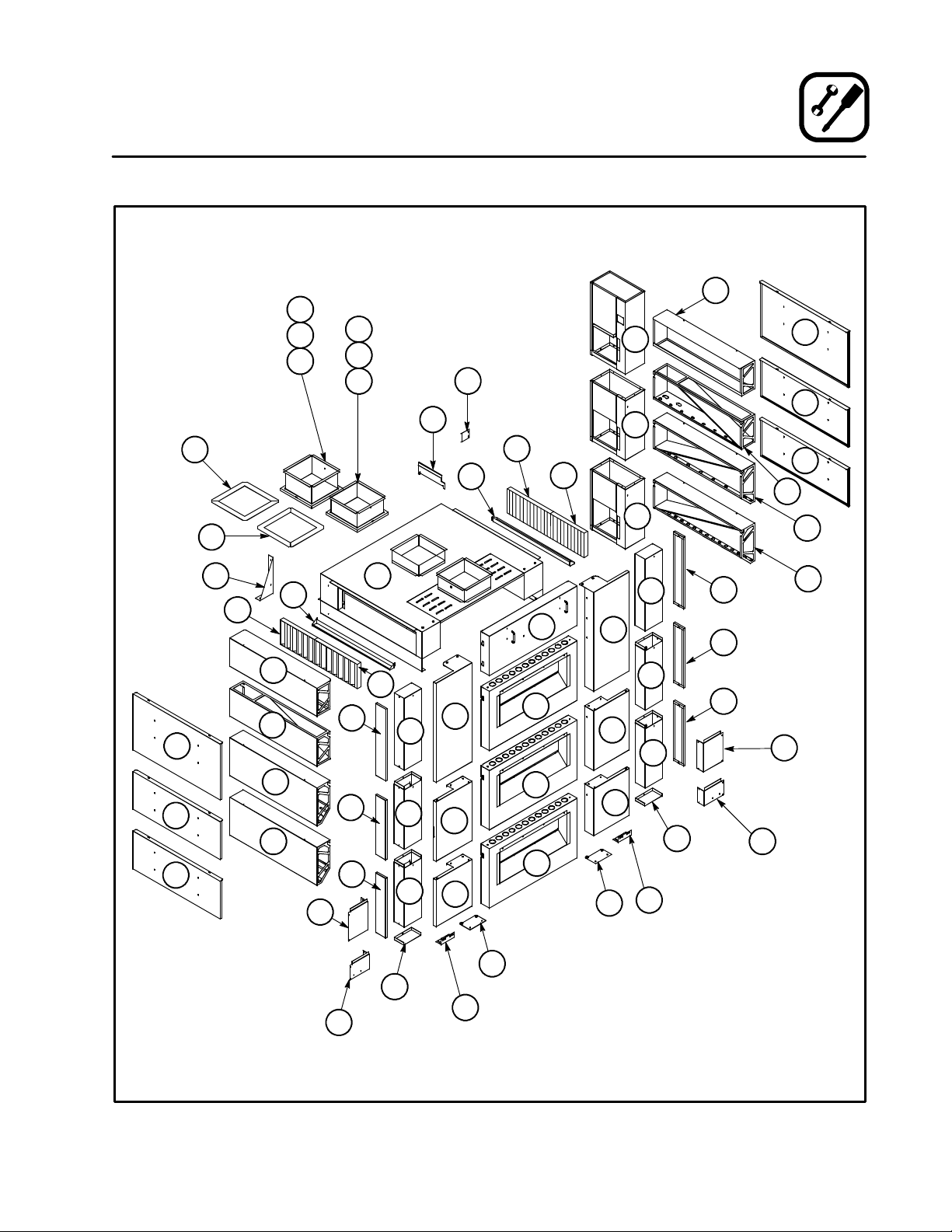
NOTE: The reference numbers given in the parts
lists also appear in brackets within the assembly sections of this document.
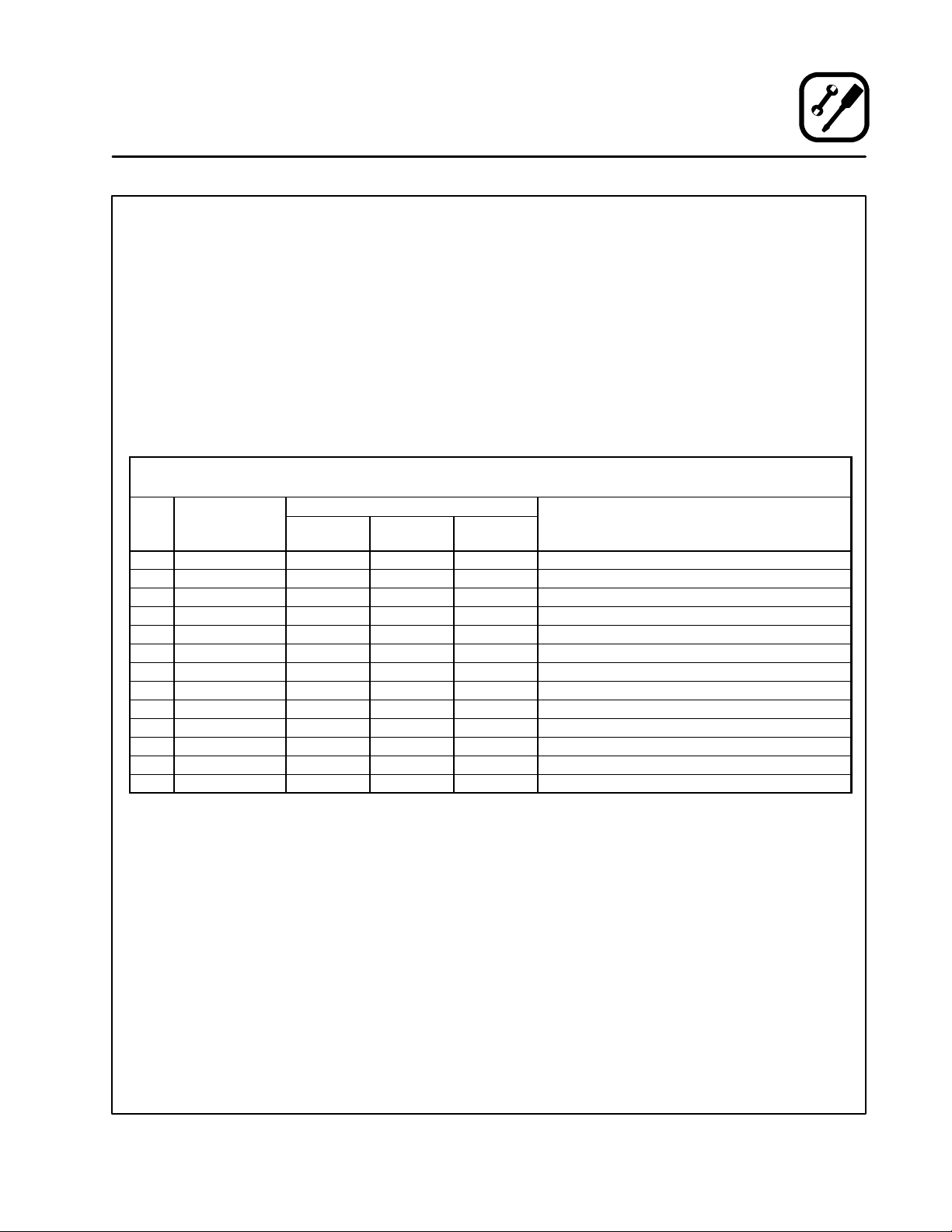
HARDWARE KIT (All Models)
Single Model: P/N ASVIBHDKIT -1, Double Model: P/N ASVIBHDKIT-2, Triple Model: P/N ASVIBHDKIT-3
REF
# P/N
K1 1 1 1 Installation Instructions, VIB Series
K2 FASCW0011 2 7 12 Screw, #10x1/2 Sheet Metal (Self drilling)
K3 FABLT5121 4 4 4 Screw, Hex Head, 3/8---16 x 1”
K4 FAWSH073 4 4 4 Washer, Flat 3/8
K5 FAWSH072 4 4 4 Washer, Lock 3/8
K6 FABLT4092 4 10 12 Screw,HexHead1/4---20x1”S/S
K7 FAWSH046 8 20 24 Washer, 1/4 Flat
K8 FAWSH045W 4 10 12 Washer, Lock 1/4
K9 FANUT0400 4 9 12 Nut, 1/4 ---20
K10 M3828 2 2 2 Stacking Pins
K11 FABLT0001 4 4 4 S c r e w , # 1 0 --- 2 4 x 3 / 8 ” P h i l i p s H e a d
K12 RPBLT0001 0 1 2 Shoulder Bolt, 1/4 --- 20 x 1 1/2” S/S
K13 FANUT0416 0 2 2 Nut, 1/4 --- 20 Lock
ORDERING
Single
Models
QUANTITY DESCRIPTION
Double
Models
Trip l e
Models
01=Top Oven, 02=Second Oven Down
03= Bottom Oven of a Triple Stack
3
Page 5
Installation
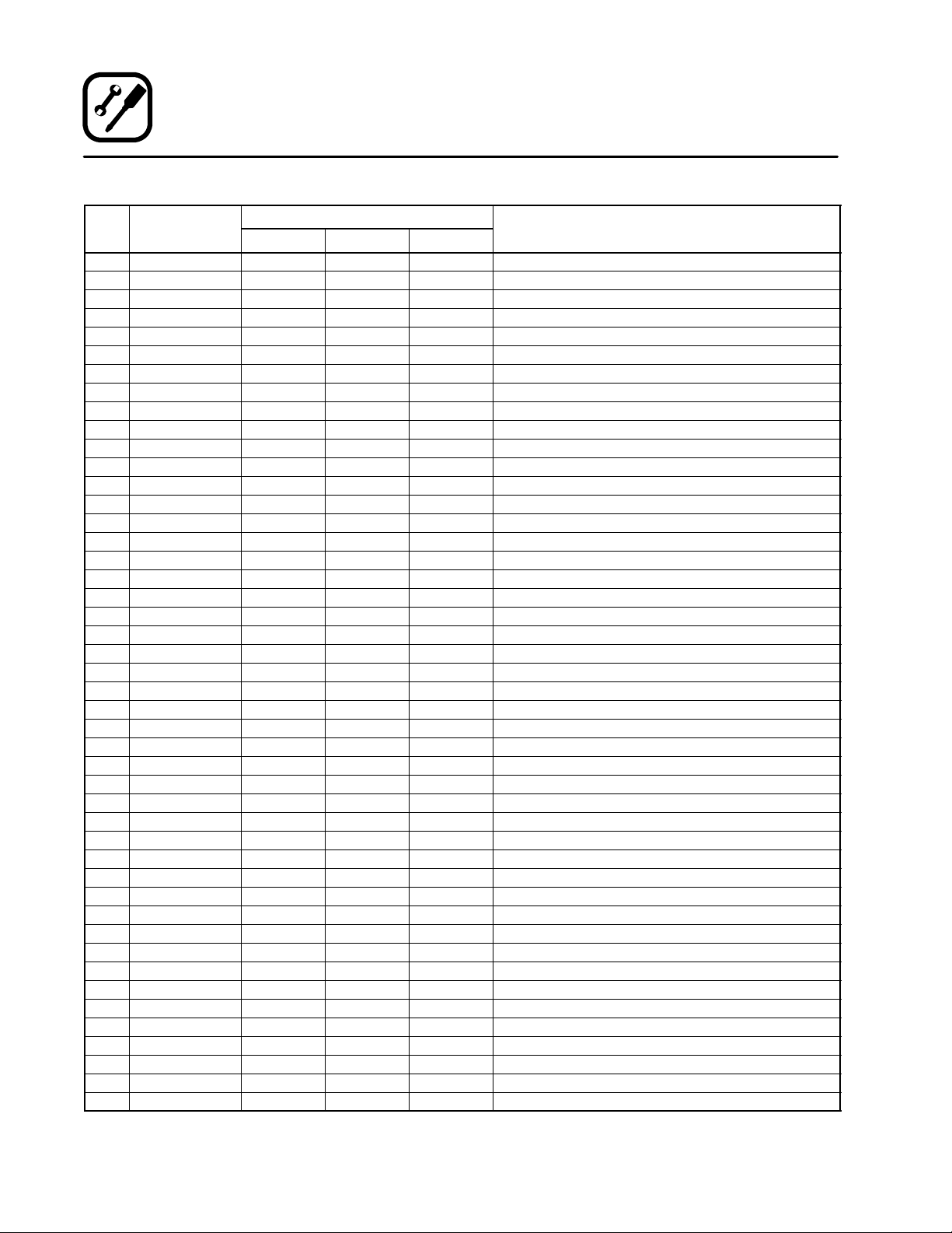
VIB3240 Parts List
REF
# P/N
01 VIB3240--- 001 1 1 1 Assy, AMU Support Bracket, O1 LH
02 VIB3240--- 002 1 1 1 Assy, Vertical Exh Plenum O1 LH
05 VIB3240--- 005 2 2 0 Bracket, AMU Bottom Support O1+O2
06 VIB3240--- 006 1 1 0 Back Plate, AMU Support Bracket O1+O2 LH
07 VIB3240--- 007 1 1 1 Assy,UpperExhPlenum,O1LH
08 VIB3240--- 008 1 1 1 Assy,UpperExhPlenum,O1RH
09 VIB3240--- 009 1 1 1 Assy, Heat Shield, O1 LH
10 VIB3240--- 010 0 1 1 Assy, AMU Support Bracket, O2 LH
11 VIB3240--- 011 1 1 1 Bracket, O1, Left Hand
12 VIB3240--- 012 1 1 1 Assy, Vertical Exh Plenum O1 RH
15 VIB3240--- 015 2 2 2 Plate, Block Off, Vert Exh Plenum, LH+RH
16 VIB3240--- 016 1 1 0 Back Plate, AMU Support Bracket O1+O2 RH
17 VIB3240--- 017 1 1 1 Assy,LowerExhPlenum,O1LH
18 VIB3240--- 018 1 1 1 Assy,LowerExhPlenum,O1RH
19 VIB3240--- 019 1 1 1 Assy, Heat Shield, O1 RH
20 VIB3240--- 020 0 1 2 Assy, Vertical Exh Plenum O2+O3 LH
22 VIB3240--- 022 0 1 2 Assy, Vertical Exh Plenum O2+O3 RH
23 VIB3240--- 023 1 1 1 PlenumAssy,AMU,Upper
25 VIB3240--- 025 1 2 3 PlenumAssy,AMU,O1+O2+O3
27 VIB3240--- 027 0 1 1 Assy,ExhPlenum,O2LH
28 VIB3240--- 028 0 1 1 Assy,ExhPlenum,O2RH
29 VIB3240--- 029 0 1 2 Assy, Heat Shield, O2+O3 LH
31 VIB3240--- 031 1 1 1 Assy, AMU/Exhaust Manifold
37 VIB3240--- 037 0 0 1 Assy,ExhPlenum,O3LH
38 VIB3240--- 038 0 0 1 Assy,ExhPlenum,O3RH
39 VIB3240--- 039 0 1 2 Assy, Heat Shield, O2+O3 RH
40 VIB3240--- 040 1 1 1 Assy, Cooling Fan Exh Plenum O1
44 VIB3240--- 044 1 1 1 Assy, Mounting Bracket, Cooling Fan Exh Plenum
45 VIB3240--- 045 0 1 2 Assy, Cooling Fan Exh Plenum O2+O3
47 VIB3240--- 047 2 2 2 Filter Trough / Receptacle
50 VIB3240--- 050 1 1 1 Assy, AMU Support Bracket, O1 RH
51 VIB3240--- 051 0 0 2 Bracket, AMU Bottom Support O3
57 VIB3240--- 057 1 1 1 Assy, AMU Duct Extension
60 VIB3240--- 060 0 1 1 Assy, AMU Support Bracket, O2 RH
61 VIB3240--- 061 1 1 1 Assy,MountingBracket,Ver.A,CoolingFanExhPlenum
67 VIB3240--- 067 1 1 1 Assy, Exhaust Duct Extension
70 VIB3240--- 070 2 2 2 Assy, Heat Sheild, Vert Exh Plenum O1
71 VIB3240--- 071 0 2 4 Assy, Heat Sheild, Vert Exh Plenum O2+O3
72 VIB3240--- 072 2 2 2 Trim,Ceiling,AMUDuct
73 VIB3240--- 073 2 2 2 Trim,Ceiling,ExhaustDuct
80 VIB3240--- 080 0 0 1 Assy, AMU Support Bracket, O3 LH
86 VIB3240--- 086 0 0 1 Back Plate, AMU Support Bracket O3 LH
90 VIB3240--- 090 0 0 1 Assy, AMU Support Bracket, O3 RH
91 VIB3240--- 091 1 1 1 Assy,MountingBracket,Ver.B,CoolingFanExhPlenum
96 VIB3240--- 096 0 0 1 Back Plate, AMU Support Bracket O3 RH
F1 ASFLT1016AL 4 4 4 Filter, 10” x 16
ORDERING
QUANTITY DESCRIPTION
VIB3240---1 VIB3240---2 VIB3240---3
01=TopOven, 02=SecondOven Down
03= Bottom Oven of a Triple Stack
4
Page 6
73
72
67
87
98
57
77
97
91
44
47
F1
F1
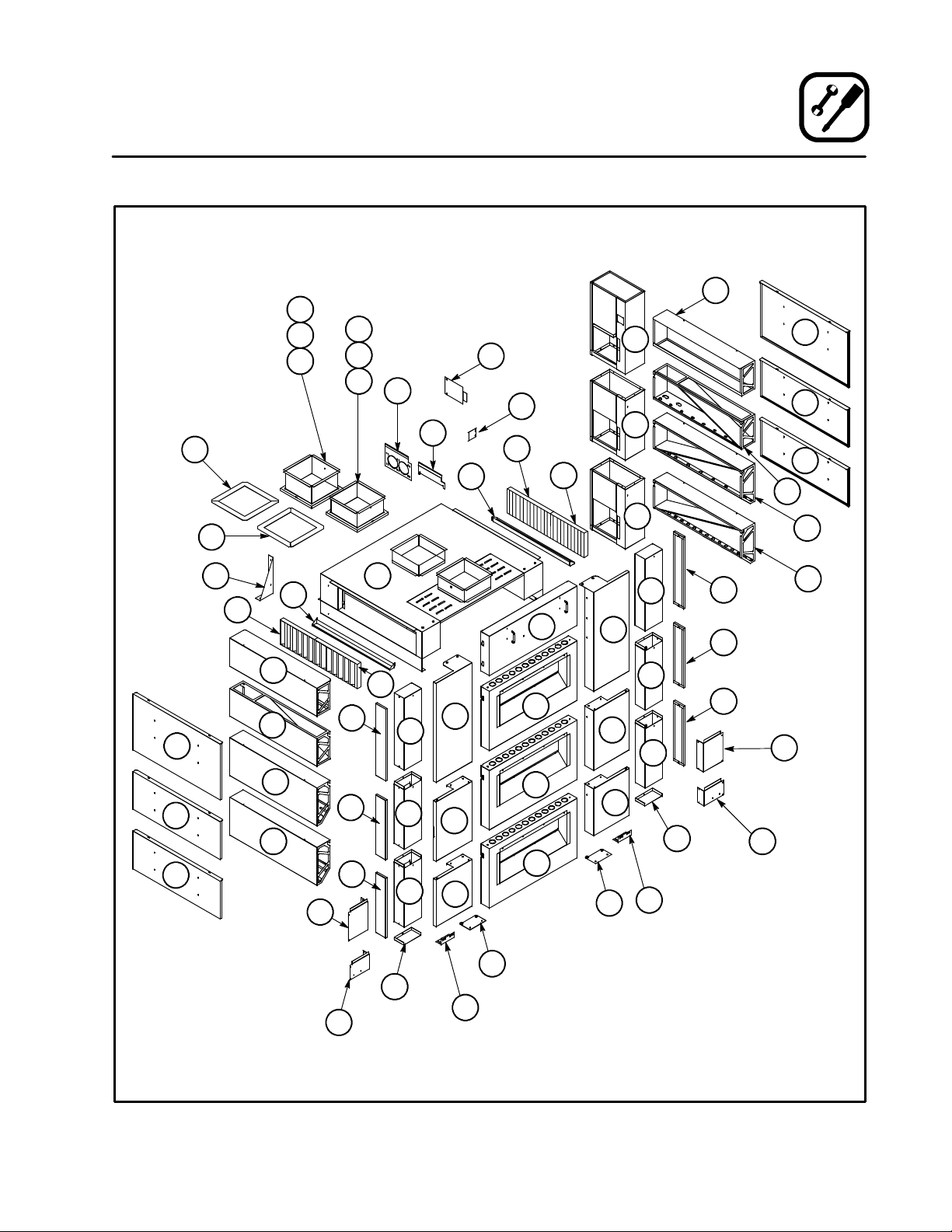
Installation
VIB3240 Parts List
8
40
45
45
19
39
39
18
28
29
29
11
47
F1
7
17
9
27
37
6
86
71
70
71
31
F1
15
20
20
12
23
1
2
10
80
51
25
25
25
5
60
5
50
22
22
90
51
70
71
71
15
38
16
96
5
Page 7
Installation
VIB3855 Parts List
REF
# P/N
01 VIB3855--- 001 1 1 1 Assy, AMU Support Bracket, O1 LH
02 VIB3855--- 002 1 1 1 Assy, Vertical Exh Plenum O1 LH
05 VIB3855--- 005 2 2 0 Bracket, AMU Bottom Support O1+O2
06 VIB3855--- 006 1 1 0 Back Plate, AMU Support Bracket O1+O2 LH
07 VIB3855--- 007 1 1 1 Assy,UpperExhPlenum,O1LH
08 VIB3855--- 008 1 1 1 Assy,UpperExhPlenum,O1RH
09 VIB3855--- 009 1 1 1 Assy, Heat Shield, O1 LH
10 VIB3855--- 010 0 1 1 Assy, AMU Support Bracket, O2 LH
11 VIB3855--- 011 1 1 1 Bracket, O1, Left Hand
12 VIB3855--- 012 1 1 1 Assy, Vertical Exh Plenum O1 RH
15 VIB3855--- 015 2 2 2 Plate, Block Off, Vert Exh Plenum, LH+RH
16 VIB3855--- 016 1 1 0 Back Plate, AMU Support Bracket O1+O2 RH
17 VIB3855--- 017 1 1 1 Assy,LowerExhPlenum,O1LH
18 VIB3855--- 018 1 1 1 Assy,LowerExhPlenum,O1RH
19 VIB3855--- 019 1 1 1 Assy, Heat Shield, O1 RH
20 VIB3855--- 020 0 1 2 Assy, Vertical Exh Plenum O2+O3 LH
22 VIB3855--- 022 0 1 2 Assy, Vertical Exh Plenum O2+O3 RH
23 VIB3855--- 023 1 1 1 PlenumAssy,AMU,Upper
25 VIB3855--- 025 1 2 3 PlenumAssy,AMU,O1+O2+O3
27 VIB3855--- 027 0 1 1 Assy,ExhPlenum,O2LH
28 VIB3855--- 028 0 1 1 Assy,ExhPlenum,O2RH
29 VIB3855--- 029 0 1 2 Assy, Heat Shield, O2+O3 LH
31 VIB3855--- 031 1 1 1 Assy, AMU/Exhaust Manifold
37 VIB3855--- 037 0 0 1 Assy,ExhPlenum,O3LH
38 VIB3855--- 038 0 0 1 Assy,ExhPlenum,O3RH
39 VIB3855--- 039 0 1 2 Assy, Heat Shield, O2+O3 RH
40 VIB3855--- 040 1 1 1 Assy, Cooling Fan Exh Plenum O1
44 VIB3240--- 044 1 1 1 Assy, Mounting Bracket, Cooling Fan Exh Plenum
45 VIB3855--- 045 0 1 2 Assy, Cooling Fan Exh Plenum O2+O3
47 VIB3855--- 047 2 2 2 Filter Trough / Receptacle
50 VIB3855--- 050 1 1 1 Assy, AMU Support Bracket, O1 RH
51 VIB3855--- 051 0 0 2 Bracket, AMU Bottom Support O3
57 VIB3855--- 057 1 1 1 Assy, AMU Duct Extension
60 VIB3855--- 060 0 1 1 Assy, AMU Support Bracket, O2 RH
61 VIB3855--- 061 1 1 1 Assy,MountingBracket,Ver.A,CoolingFanExhPlenum
67 VIB3855--- 067 1 1 1 Assy, Exhaust Duct Extension
70 VIB3855--- 070 2 2 2 Assy, Heat Sheild, Vert Exh Plenum O1
71 VIB3855--- 071 0 2 4 Assy, Heat Sheild, Vert Exh Plenum O2+O3
72 VIB3855--- 072 2 2 2 Trim,Ceiling,AMUDuct
73 VIB3855--- 073 2 2 2 Trim,Ceiling,ExhaustDuct
80 VIB3855--- 080 0 0 1 Assy, AMU Support Bracket, O3 LH
81 VIB3855--- 081 0 0 0or1* Plate, Block Off, Cooling Exh Plenum*
86 VIB3855--- 086 0 0 1 Back Plate, AMU Support Bracket O3 LH
90 VIB3855--- 090 0 0 1 Assy, AMU Support Bracket, O3 RH
91 VIB3855--- 091 1 1 1 Assy,MountingBracket,Ver.B,CoolingFanExhPlenum
96 VIB3855--- 096 0 0 1 Back Plate, AMU Support Bracket O3 RH
F1 ASFLT1016AL 2 2 2 Filter, 10” x 16
F2 ASFLT1020AL 2 2 2 Filter, 10” x 20
* = only included in Conversion Kit VIB3855 --- B3 for converting an AB2B to a VIB3855 --- 3
ORDERING
QUANTITY DESCRIPTION
VIB3855---1 VIB3855---2 VIB3855---3
01=TopOven, 02=SecondOven Down
03= Bottom Oven of a Triple Stack
6
Page 8
73
72
67
87
98
57
77
97
61
91
47
81
F2
44
F1
Installation
VIB3855 Parts List
8
40
45
45
19
39
39
18
28
29
29
11
47
F1
7
17
9
27
37
6
86
71
70
71
31
F2
15
20
20
12
23
1
2
10
80
51
25
25
25
5
60
5
50
22
22
90
51
70
71
71
15
38
16
96
7
Page 9
Installation
VIB3870 Parts List
REF
# P/N
01 VIB3855--- 001 1 1 1 Assy, AMU Support Bracket, O1 LH
02 VIB3855--- 002 1 1 1 Assy, Vertical Exh Plenum O1 LH
05 VIB3855--- 005 2 2 0 Bracket, AMU Bottom Support O1+O2
06 VIB3855--- 006 1 1 0 Back Plate, AMU Support Bracket O1+O2 LH
07 VIB3855--- 007 1 1 1 Assy,UpperExhPlenum,O1LH
08 VIB3855--- 008 1 1 1 Assy,UpperExhPlenum,O1RH
09 VIB3855--- 009 1 1 1 Assy, Heat Shield, O1 LH
10 VIB3855--- 010 0 1 1 Assy, AMU Support Bracket, O2 LH
11 VIB3855--- 011 1 1 1 Bracket, O1, Left Hand
12 VIB3855--- 012 1 1 1 Assy, Vertical Exh Plenum O1 RH
15 VIB3855--- 015 2 2 2 Plate, Block Off, Vert Exh Plenum, LH+RH
16 VIB3855--- 016 1 1 0 Back Plate, AMU Support Bracket O1+O2 RH
17 VIB3855--- 017 1 1 1 Assy,LowerExhPlenum,O1LH
18 VIB3855--- 018 1 1 1 Assy,LowerExhPlenum,O1RH
19 VIB3855--- 019 1 1 1 Assy, Heat Shield, O1 RH
20 VIB3855--- 020 0 1 2 Assy, Vertical Exh Plenum O2+O3 LH
22 VIB3855--- 022 0 1 2 Assy, Vertical Exh Plenum O2+O3 RH
23 VIB3870--- 023 1 1 1 PlenumAssy,AMU,Upper
25 VIB3870--- 025 1 2 3 PlenumAssy,AMU,O1+O2+O3
27 VIB3855--- 027 0 1 1 Assy,ExhPlenum,O2LH
28 VIB3855--- 028 0 1 1 Assy,ExhPlenum,O2RH
29 VIB3855--- 029 0 1 2 Assy, Heat Shield, O2+O3 LH
31 VIB3870--- 031 1 1 1 Assy, AMU/Exhaust Manifold
37 VIB3855--- 037 0 0 1 Assy,ExhPlenum,O3LH
38 VIB3855--- 038 0 0 1 Assy,ExhPlenum,O3RH
39 VIB3855--- 039 0 1 2 Assy, Heat Shield, O2+O3 RH
40 VIB3870--- 040 1 1 1 Assy, Cooling Fan Exh Plenum O1
44 VIB3870--- 044 1 1 2 Assy, Mounting Bracket, Cooling Fan Exh Plenum
45 VIB3870--- 045 0 1 2 Assy, Cooling Fan Exh Plenum O2+O3
47 VIB3855--- 047 2 2 2 Filter Trough / Receptacle
50 VIB3855--- 050 1 1 1 Assy, AMU Support Bracket, O1 RH
51 VIB3855--- 051 0 0 2 Bracket, AMU Bottom Support O3
57 VIB3855--- 057 1 1 1 Assy, AMU Duct Extension
60 VIB3855--- 060 0 1 1 Assy, AMU Support Bracket, O2 RH
61 VIB3870--- 061 1 1 1 Assy,MountingBracket,Ver.A,CoolingFanExhPlenum
67 VIB3855--- 067 1 1 1 Assy, Exhaust Duct Extension
70 VIB3855--- 070 2 2 2 Assy, Heat Sheild, Vert Exh Plenum O1
71 VIB3855--- 071 0 2 4 Assy, Heat Sheild, Vert Exh Plenum O2+O3
72 VIB3855--- 072 2 2 2 Trim,Ceiling,AMUDuct
73 VIB3855--- 073 2 2 2 Trim,Ceiling,ExhaustDuct
80 VIB3855--- 080 0 0 1 Assy, AMU Support Bracket, O3 LH
86 VIB3855--- 086 0 0 1 Back Plate, AMU Support Bracket O3 LH
90 VIB3855--- 090 0 0 1 Assy, AMU Support Bracket, O3 RH
91 VIB3870--- 091 1 1 1 Assy,MountingBracket,Ver.B,CoolingFanExhPlenum
96 VIB3855--- 096 0 0 1 Back Plate, AMU Support Bracket O3 RH
F1 ASFLT1016AL 2 2 2 Filter, 10” x 16
F2 ASFLT1020AL 2 2 2 Filter, 10” x 20
ORDERING
QUANTITY DESCRIPTION
VIB3870---1 VIB3870---2 VIB3870---3
01=TopOven, 02=SecondOven Down
03= Bottom Oven of a Triple Stack
8
Page 10

73
72
67
87
98
57
77
97
61
91
47
F2
44
F1
Installation
VIB3870 Parts List
8
40
45
45
19
39
39
18
28
29
29
11
47
F1
7
17
9
27
37
6
86
71
70
71
31
F2
15
20
20
12
23
1
2
10
80
51
25
25
25
5
60
5
50
22
22
90
51
70
71
71
15
38
16
96
9
Page 11

Installation
Airflow Requirements
MODEL PRESSURE SUPPLY EXHAUST
VIB3240-1
Duct size 7”x12”
(17.8 x 305 mm)
VIB3240-2
Duct size 7”x12”
(17.8 x 305 mm)
VIB3240-3
Duct size 7”x12”
(17.8 x 305 mm)
VIB3855-1 CFM 1100 CFM 1500 CFM
Duct size 12” x 12”
(305 x 305 mm)
VIB3855-2
Duct size 12”x12”
(305 x 305 mm)
VIB3855-3
Duct size 12”x12”
(305 x 305 mm)
CFM 500 CFM 875 CFM
STATIC PRESSURE 0.04” W.C. (10 Pa) 0.7” W.C. (174 Pa)
CFM 750 CFM 1150 CFM
STATIC PRESSURE 0.07” W.C. (17 Pa) 1.0” W.C. (249 Pa)
CFM 1050 CFM 1450 CFM
STATIC PRESSURE 0.14” W.C. (35 Pa) 1.5” W.C. (373 Pa)
STATIC PRESSURE 0.02-0.03” W.C.
(5-7 Pa)
CFM 1450 CFM 1850 CFM
STATIC PRESSURE 0.09” W.C. (22 Pa) 1.4” W.C. (348 Pa)
CFM 1800 CFM 2200 CFM
STATIC PRESSURE 0.12” W.C. (30 Pa) 1.8” W.C. (448 Pa)
1.5” W.C. (373 Pa)
VIB3870-1 CFM 1100 CFM 1500 CFM
Duct size 12” x 12”
(305 x 305 mm)
VIB3870-2
Duct size 12”x12”
(305 x 305 mm)
VIB3870-3
Duct size 12”x12”
(305 x 305 mm)
STATIC PRESSURE 0.02-0.03” W.C.
(5-7 Pa)
CFM 1450 CFM 1850 CFM
STATIC PRESSURE 0.09” W.C. (22 Pa) 1.4” W.C. (348 Pa)
CFM 1800 CFM 2200 CFM
STATIC PRESSURE 0.12” W.C. (30 Pa) 1.8” W.C. (448 Pa)
10
1.5” W.C. (373 Pa)
Page 12
WARNING!!
Be sure that the ovens are unplugged and
the gas disconnected (if applicable).
OVEN ASSEMBLY AND STACKING
1. Assemble the oven(s) as described in the
Owner-Operator Manual provided with the appliance(s).
2. If applicable, stack the units as follows:
SG3240 Ovens --- Use the stacking pins pro-
vided with the oven to secure the decks together and prevent shifting.
MT3855 and MT3870 Ovens --- Attach the
stacking rail between each oven on the back to
secure the decks together and prevent shifting.
COOLING FAN EXHAUST PLENUM MOUNTING
BRACKETS
For Ovens with Cooling Fan Exhaust Louvers
1. Install the Mounting Bracket Version B [91] using two #10-24 x 3/8 screws provided. See
Figure 1.
NOTE: Mount with the offset going away from
theoven.Theshapeofbracket91varies with the model of the oven.
Installation
Oven Preparation
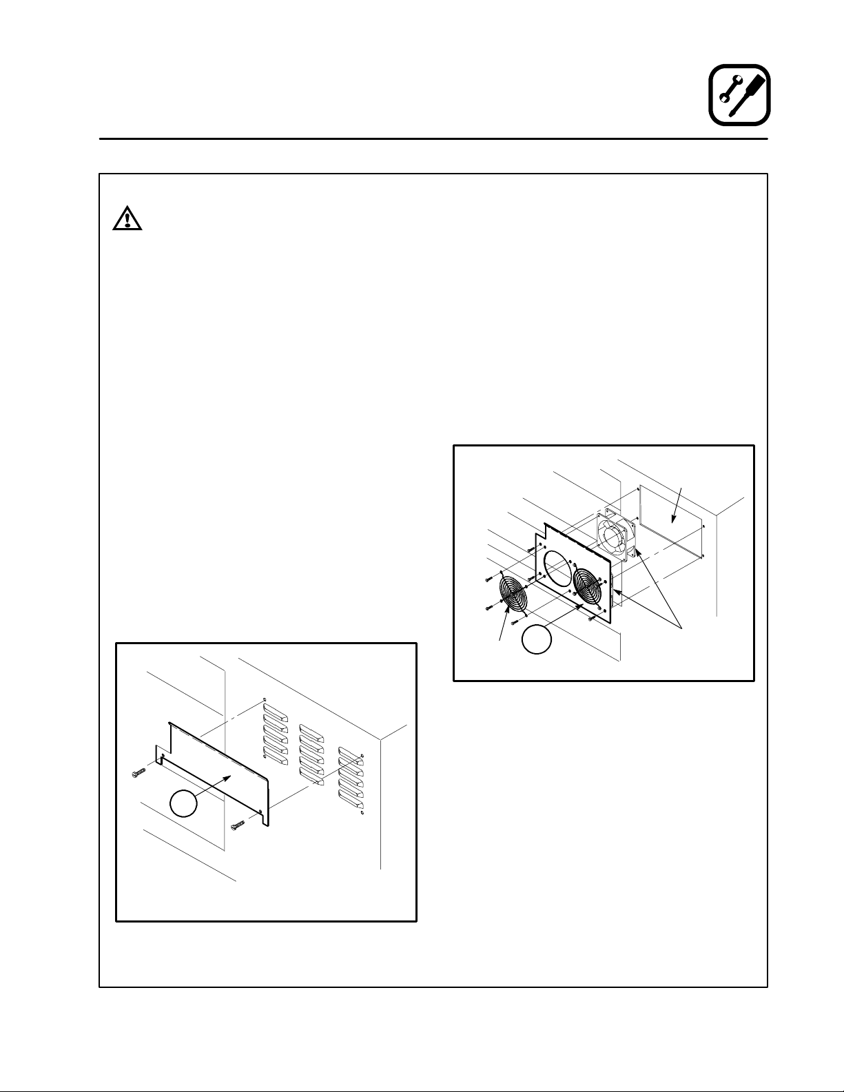
For Ovens with Plate Mounted Cooling Fans
(VIB3855 with o l der MT3855 ovens or VIB3870
with older MT3870 ovens)
1. Remove the plate in the top oven that holds the
exhaust fans in place. Disconnect the wiring.
NOTE: The plate is located on the right side
of the oven.
2. Remove the fans from the original plate and
install them, along with the grills, on the Version A Mounting Bracket [61] using the original hardware. See Figure 2.
3. Reconnect the fan motors to the wiring harness and install the assembly to the top oven
using the original screws.
OVEN
CUTOUT
EXHAUST
FAN
GRILL
61
91
Rear of Right Side of MT3855
shown with VIB3855-091 Bracket
Figure 1
Figure 2
11
Page 13

Installation
Oven Preparation
OVEN/VENT ALIGNMENT HOLES
For SG3240 and Ovens With Stacking Align-
ment Knockouts
1. Use a hammer to remove the two front knockouts. The location of the knockouts should
match t he two shown in Figure 3.
For Ovens Without Stacking Alignment Knockouts
1. Locate the front, top edge of the upper oven.
2. Drill two 7/16” diameter holes in the top of the
oven at the locations shown in Figure 3. The
holes should penetrate both the top “skin” of
the oven as well as the angle frame member.
There is no need to penetrate the top of the
oven by more than 7/8”.
3/4
2-7/16”
FRONT OF OVEN
Figure 3
12
7/16” (2 PLCS)
3/4
2-7/16”
Page 14

AMU ALIGNMENT PINS
1. Thread the two Alignment Pins [K9] into the fittings on the bottom of the AMU / Exhaust Manifold Assembly [31].
31
Installation
AMU Installation
2. Carefully lift the assembly and place it on top
of the oven(s). Insert the alignment pins into
the alignment holes to prevent the assembly
from shifting on top of the oven. See Figure 4.
ALIGNMENT
PIN
Figure 4
ALIGNMENT
HOLE
13
Page 15

Installation
AMU Installation
CORNER SUPPORT BRACKET(S)
For VIBXXXX-01 (Single Ovens)
1. Right Corner Support Bracket Assembly:
a.) A ttach Bracket [16] to the bottom rear of
Corner Support Bracket [50] using four
#10 x 1/2” self drilling screws [K2].
b.) Attach Bracket [5] to the bottom of Corner
Support Bracket [50] using two #10 x 1/2”
self drilling screws [K2].
c.) Hang the assembly on the right side of the
AMU/Exhaust Manifold Assembly [31]
leaving the two 3/8-16 hex head screws
[K6]loose.SeeFigure6.
2. Left Corner Support Bracket Assembly:
a.) A ttach Bracket [6] to the bottom rear of
Corner Support Bracket [1] using four
#10 x 1/2” self drilling screws [K2].
b.) Attach Bracket [5] to the bottom of Corner
Support Bracket [1] using two #10 x 1/2”
self drilling screws [K2].
c.) Hangtheassemblyontheleftsideofthe
AMU/Exhaust Manifold Assembly [31]
leaving the two 3/8-16 hex head screws
[K6]loose.SeeFigure6.
3. Loosen the front two leg bolts on both the front
legs enough to slide Brackets [5] under the
washers. See Figure 6. Center the Corner Support Brackets and tighten at the top and bottom
holding the brackets against the oven. Refer to
the following table for the correct distance between the brackets.
Model
VIB3240 37-5/8” (956 mm)
VIB3855 40-1/8” (1019 mm)
VIB3870 55-1/8” (1400 mm)
Distance
For VIBXXXX -02 (Double Stacked Ovens)
1. Right Corner Support Bracket Assembly:
a.) A ttach Bracket [16] to the bottom rear of
Corner Support Bracket [60] using four
#10 x 1/2” self drilling screws [K2].
b.) Attach Bracket [5] to the bottom of Corner
Support Bracket [60] using two #10 x 1/2”
self drilling screws [K2].
c.) Attach Corner Support Bracket [60] to
Corner Support Bracket [50] using 1/4-20
x 1” hex head bolts[K6], 1/4” flatwashers
[K7], 1/4” lockwashers [K8], and 1/4-20
nuts [K9]. Tighten securely while aligned.
d.) Hang the assembly on the right side of the
AMU/Exhaust Manifold Assembly [31]
leaving the two 3/8-16 hex head screws
[K6]loose.SeeFigure6.
2. Left Corner Support Bracket Assembly:
a.) A ttach Bracket [6] to the bottom rear of
Corner Support Bracket [10] using four
#10 x 1/2” self drilling screws [K2].
b.) Attach Bracket [5] to the bottom of Corner
Support Bracket [10] using two #10 x 1/2”
self drilling screws [K2].
c.) Attach Corner Support Bracket [1] to Cor-
ner Support Bracket [10] using 1/4-20 x 1”
hex head bolts[K6], 1/4” flatwashers [K7],
1/4” lockwashers [K8], and 1/4-20 nuts
[K9]. Tighten securely while aligned.
d.) Hangtheassemblyontheleftsideofthe
AMU/Exhaust Manifold Assembly [31]
leaving the two 3/8-16 hex head screws
[K6]loose.SeeFigure6.
3. Loosen the front two leg bolts on both the front
legs enough to slide Brackets [5] under the
washers. See Figure 6. Center the Corner Support Brackets and tighten at the top and bottom
holding the brackets against the oven. Refer to
the following table for the correct distance between the brackets.
Model
Distance
14
VIB3240 37-5/8” (956 mm)
VIB3855 40-1/8” (1019 mm)
VIB3870 55-1/8” (1400 mm)
Page 16

Installation
AMU Installation
For VIBXXXX-03 (Triple Stacked Ovens)
1. Right Corner Support Bracket Assembly:
a.) A ttach Bracket [96] to the bottom rear of
Corner Support Bracket [90] using four
#10 x 1/2” self drilling screws [K2].
b.) Attach Bracket [51] to the bottom of Cor-
ner Support Bracket [96] using two #10 x
1/2” self drilling screws [K2].
c.) Attach Corner Support Bracket [50], Cor-
ner Support Bracket [60] and Corner Support Bracket [90] using 1/4-20 x 1” hex
head bolts[K6], 1/4” flatwashers [K7],
1/4” lockwashers [K8], and 1/4-20 nuts
[K9]. Tighten securely while aligned.
d.) Hang the assembly on the right side of the
AMU/Exhaust Manifold Assembly [31]
leaving the two 3/8-16 hex head screws
[K6]loose.SeeFigure6.
2. Left Corner Support Bracket Assembly:
a.) A ttach Bracket [86] to the bottom rear of
Corner Support Bracket [80] using four
#10 x 1/2” self drilling screws [K2].
b.) Attach Bracket [51] to the bottom of Cor-
ner Support Bracket [86] using two #10 x
1/2” self drilling screws [K2].
c.) Attach Corner Support Bracket [1], Cor-
ner Support Bracket [10] and Corner Support Bracket [80] using 1/4-20 x 1” hex
head bolts[K6], 1/4” flatwashers [K7],
1/4” lockwashers [K8], and 1/4-20 nuts
[K9]. Tighten securely while aligned.
d.) Hangtheassemblyontheleftsideofthe
AMU/Exhaust Manifold Assembly [31]
leaving the two 3/8-16 hex head screws
[K6]loose.SeeFigure6.
3. Loosen the front two caster bolts on both the
right and left sides enough to slide Brackets [5]
under the washers. See Figure 6. Center the
Corner Support Brackets and tighten at the top
and bottom holding the brackets against the
oven. Refer to the following table for the correct
distance between the brackets.
Model
VIB3240 37-5/8” (956 mm)
VIB3855 40-1/8” (1019 mm)
VIB3870 55-1/8” (1400 mm)
Distance
15
Page 17

Installation
AMU Installation
50
80
10
1
60
90
LOCATION OF
BRACKET,
AMU BOTTOM
SUPPORT
(if single oven)
DOUBLE DECK
BRACKET
LOCATION
50
5
60
90
Figure 5
16
Page 18

AMU SUPPORT BRACKETS
For VIBXXXX -1 (Single Ovens) and
VIBXXXX-2 (Double Stacked Ovens)
1. Secure the AMU Bottom Support Bracket
01-02 [5] below the right front support leg
mounting flange. Use the same inner, front
bolt and washer that secures the leg in place.
2. Repeat STEP 1 for the left front support leg.
NOTE: Both AMU support brackets should be
parallel and square and held firmly against
the front of the oven(s).
Installation
AMU Installation
For VIBXXXX-3 (T riple Stacked Ovens)
NOTE: The AMU Bottom Support Bracket is at-
tached to the AMU Bottom Support Bracket Back Plates at the factory.
1. Secure the Right AMU Bottom Support Bracket 03 [51] to the caster plate on the oven as follows:
e.) Loosen the two outer bolts on the caster
plate.
f.) Slide the assembly between the plate and
washers.
g.) Re-tighten the bolts.
2. Repeat STEP 1 for the Left AMU Bottom Support Bracket 03 [51].
Figure 6
6
51
Figure 7
80
17
Page 19

Installation
AMU Installation
AMU INSTALLATION
1. Place the Lower AMU Plenum Assembly 02
[25] on the pins of the AMU Support Bracket
01 [50 right, 1 left].
2. Place the Middle AMU Plenum Assembly 02
[25] on the pins of the AMU Support Bracket
01[60right,10left].
3. Place the Upper AMU Plenum Assembly 02
[25] on the pins of the AMU Support Bracket
01 [50 right, 1 left].
4. Place the Plenum Assembly [23] on the upper
pins of the AMU Support Bracket 01 [50 right,
1left].
23
25
Figure 8
18
25
25
Page 20

VERTICAL EXHAUST PLENUM ASSEMBLY
NOTE: For VIBXXXX-1 (single ovens) complete
steps1,4and6.ForVIBXXXX-2(double
stacked ovens) complete steps 1, and 3 - --6.
For VIBXXXX-3 (triple stacked ovens) completeallofthesteps.
Use the following instructions to install the left and
right Vertical Exhaust Plenums.
1. All Models --- Attach the Block Off Plate [15
right and left] to bottom of [2 and 12 if
VIBXXX-1] [20 and 22 if VIBXXXX- 2 or
VIBXXXX-3] using #10-24x3/8” Phillips Head
Screws. See Figure 9.
2. Triple Stacked Ovens Only --- Attach the
Lower Vertical Exhaust Plenum Assembly 03
[22 right, 20 left] to the AMU Support Bracket
Assembly 02 [60 right, 10 left] by aligning the
pin on the vertical exhaust plenum to the slot
on the back of the right AMU support bracket.
3. Double and Triple Stacked Ovens Only --- A t -
tach the Middle Vertical Exhaust Plenum As-
Installation
Exhaust Installation
sembly 02 [22 right, 20 left] to the AMU Support Bracket Assembly 01 [50 right, 1 left] by
aligning the pin on the vertical exhaust plenum
to the slot on the back of the AMU support
bracket.
4. All Models --- Attach the Vertical Exhaust Ple-
num Assembly 01 [12 right, 2 left] to the AMU
Support Bracket Assembly 01 [50 right, 1 left]
by aligning the pin on the vertical exhaust plenum to the slot on the back of the AMU support brack et.
5. Double and Triple Stacked Ovens Only --- A t -
tach the Heat Shield 02-03 [71 right and left]
to the Vertical Exhaust Plenum 03 [22 right, 20
left] by aligning the slots in the heat shield with
the pins on the vertical exhaust plenum.
6. All Models --- Attach the Heat Shield 01 [70
right and left] to the Vertical Exhaust Plenum
Assembly 01 [12 right, 2 left] by aligning the
slots in the heat shield with the pins on the vertical exhaust plenum.
70
LOCATION OF
[15] FOR
VIBXXXX-1
71
LOCATION OF
[15] FOR
VIBXXXX-2
71
15
12
40
22
45
22
45
LOCATION OF [ 15] FORVIBXXXX-3
Figure 9
19
Page 21

Installation
Exhaust Installation
COOLING FAN EXHAUST PLENUM
For VIBXXXX-3 (T riple Stacked Ovens)
1. Attach the lower Cooling Fan Exhaust Plenum
Assembly [45] to the upper Cooling Fan Exhaust Plenum Assembly [45] using #10x1/2”
self drilling screws [K10].
2. Attach the Cooling Fan Exhaust Plenum Assembly 01 [40] to the oven by aligning the
flange on cooling fan exhaust plenum with the
Mounting Bracket Assembly [61 or 91].
3. Install Bracket (44) to the rear of the top oven
to hold the lower Cooling Fan Exhaust Plenum Assembly [45] and the upper Cooling
Fan Exhaust Plenum Assembly [45] forward.
For VIBXXXX-2 (Double Stacked Ovens)
1. Attach the Upper Cooling Fan Exhaust Plenum Assembly [40] to the Cooling Fan Exhaust Plenum Assembly 01 [45] using
#10x1/2” s elf drilling screws [K10].
2. Attach the Cooling Fan Exhaust Plenum Assembly 01 [40] to the oven by aligning the
flange on cooling fan exhaust plenum with the
Mounting Bracket Assembly [61 or 91].
3. Install Bracket (44) to the rear of the top oven
to hold the lower Cooling Fan Exhaust Plenum Assembly [45] and the upper Cooling
Fan Exhaust Plenum Assembly [45] forward.
For VIBXXXX-1 (Single Ovens)
1. Attach the Cooling Fan Exhaust Plenum Assembly 01 [40] to the oven by aligning the
flange on cooling fan exhaust plenum with the
Mounting Bracket Assembly [61 or 91].
40
45
44
Figure 10
FLANGE
40
31
61
91
20
Page 22

EXHAUST PLENUM HANGING PIN
WARNING!!
The hole location described below
should not interfere with any oven control
center components. Care must be taken
when locating and drilling this hole to
avoid damage to internal components.
Use the following procedure to install the exhaust
plenum hanging pins on VIBXXXX-02 (double
stacked ovens) and VIBXXXX- 03 (triple stacked
ovens).
1. On the first and second decks drill one 1/4” diameter hole into the upper control cabinet.
SeeFigure11.
NOTE: The distance from the top of the upper
oven to the center line of the hole
should be the same as the distance
from the top of the upper oven center
lineofthepinweldedinthesurfaceof
the Left Vertical Exhaust Plenum Assembly 01 [2].
2. Remove the electrical box cover.
3. Remove the chain guards from the ovens.
4. Insert one 1/4”-20 Custom Shoulder Bolt
[K12] through the hole. Secure the bolt in
place with one 1/4” Flat Washer [K3] and one
1/4”-20 Lock Nut [K13].
5. Reinstall the chain guards in the electrical box.
6. Reinstall the electrical box cover.
Installation
Exhaust Installation
1
15-19/32
FRONT VIEW
21
Figure 11
Page 23

Installation
Exhaust Installation
TOP OVEN BRACKET
1. Locate Left Bracket 01[11] at the junction of
the AMU Exhaust Manifold Assembly [31] and
the forward inboard edge of the upper oven
electrical box. The forward edge of the bracket
should be vertical.
2. Attach the bracket using #10x1/2” Self Drilling
Screws [K10].
11
Figure 12
22
Page 24

FILTERS
1. Install one Filter Trough/Receptacle [47] into
the opening in each end of the AMU Exhaust
Manifold Assembly [31].
NOTE: The tabs in the filter trough/receptacle fit
into the slots on the sides of the openings in the AMU exha u st manifold.
For VIB3240
1. Insert one 10” x 16” Filter [F1] into each end
of the AMU Exhaust Manifold Assembly [31]
as follows:
a.) Install the top of the filter into the channel
in the top of the AMU Exhaust Manifold
first.
b.) Then allow the bottom of the filter to drop
into the Filter Trough/Receptacle [47].
2. Repeat on the other end of the oven.
Installation
Exhaust Installation
For VIB3855 and VIB3870
1. Insert one 10” x 16” (254 x 406.4mm) Filter
[F1] and one 10” x 20” (254 x 508mm) Filter
[F2] into each end of the AMU Exhaust Manifold Assembly [31] as follows:
a.) Install the top of the filters into the channel
in the top of the AMU Exhaust Manifold
first.
b.) Then allow the bottom of the filters to drop
into the Filter Trough/Receptacle [47].
2. Repeat on the other end of the oven.
Figure 13
47
23
Page 25

Installation
Exhaust Installation
RIGHT EXHAUST PLENUM AND HEAT SHIELD
Use the following instructions to installthe right Exhaust Plenums and Heat Shields.
To p D e c k
1. Mount the Right Lower Exhaust Plenum Assembly 01 [18] in place. The slots on t he sides
towards the rear of the lower exhaust plenum
fit over the pins in the Cooling Fan Exhaust
Plenum Assembly 01 [40] and the Vertical Exhaust Plenum Assembly 01 [12].
2. Mount the Right Upper Exhaust Plenum Assembly 01 [8] in place. See Figure 14.
3. Mount the Right Heat Shield 01 [19] by aligning the slots over the pins on the upper exhaust plenum assembly.
Second Deck (if applicable)
1. Mount the Right Exhaust Plenum Assembly 02
[28] in place. The slots on the sides towards
the rear of the exhaust plenum fit over the pins
in the Cooling Fan Exhaust Plenum Assembly
[45] and the Vertical Exhaust Plenum Assembly [22].
2. Mount the Right Heat Shield 02 [39] by aligning the slots over the pins on the exhaust plenum assembly.
Third Deck (if applicable)
1. Mount the Right Exhaust Plenum Assembly 03
[38] in place. The slots on the s ides towards
the rear of the exhaust plenum fit over the pins
in the Cooling Fan Exhaust Plenum Assembly
[45] and the Vertical Exhaust Plenum Assembly [22].
2. Mount the Right Heat Shield 03 [39] by aligning the slots over the pins on the exhaust plenum assembly.
39
39
8
40
19
18
45
28
45
38
Figure 14
24
Page 26

LEFT EXHAUST PLENUM AND HEAT SHIELD
Use the following instructions to install the left Exhaust Plenums and Heat Shields.
To p D e c k
1. Mount the Left Lower Exhaust Plenum Assembly 01 [17] in place. The slots on the sides towards the rear of the lower exhaust plenum fit
over the pins in the Left Bracket 01 [11] and
the Left Vertical Exhaust Plenum Assembly 01
[2].
2. Mount the Left Upper Exhaust Plenum Assem bly 01 [7] in place. See Figure 15.
3. Mount the Left Heat Shield 01 [9] by aligning
the slots over the pins on the upper exhaust
plenum assembly.
Second Deck (if applicable)
1. Mount the Left Exhaust Plenum Assembly 02
[27] in place. The slots on the sides towards
Installation
Exhaust Installation
the rear of the exhaust plenum fit over the Custom Shoulder Bolt [K12] in the oven’s electrical box and the Left Vertical Exhaust Plenum
Assembly [20].
2. Mount the Left Heat Shield 02 [29] by aligning
the slots over the pins on the left exhaust plenum assembly.
Third Deck (if applicable)
1. Mount the Left Exhaust Plenum Assembly 03
[37] in place. The slots on the s ides towards
the rear of the exhaust plenum fit over the Custom Shoulder Bolt [K12] in the oven’s electrical box and the Left Vertical Exhaust Plenum
Assembly [20].
2. Mount the Left Heat Shield 03 [29] by aligning
the slots over the pins on the exhaust plenum
assembly.
29
29
7
9
17
27
37
Figure 15
25
Page 27

Installation
Duct Connection
WARNING!!
The duct collar extensions are designed
to remain in place when the oven is rolled
away for maintenance or cleaning. Therefore, they should be rigidly fastened to
the ceiling structure as they are not intended to support the weight of the ductwork and/or fans.
1. Roll the oven into its operating location.
2. Install the Exhaust Duct Extension as follows:
a.) Locate the Exhaust Duct Extension As-
sembly [98, 87 or 67] on top of the exhaust
duct collar. The collar is part of the AMU
Exhaust Manifold Assembly [31].
b.) Secure the duct extension in place with
the two over-center latches. The exhaust
duct extension is designed to penetrate 8’
tall ceilings by approximately 2”.
c.) Connect the duct from the exhaust fan to
the exhaust duct extension.
3. Install the AMU Duct Extension as follows:
a.) Locate the AMU Duct Extension Assem-
bly [97, 77 or 57] on top of the air make up
duct collar. The collar is part of the AMU
Exhaust Manifold Assembly [31].
b.) Secure the duct extension in place with
the two overcenter latches. The AMU duct
extension is designed to penetrate 8’ tall
ceilings by approximately 2”.
c.) Connect the duct from the air makeup to
the AMU duct extension.
The oven(s) can now be connected to electric and
gas (if applicable) supplies.
NFPA 96, Standard for Ventilation Control and Fire
Protection of Commercial Cooking Operations,re-
quires that “hoods, grease removal devices, exhaust fans, and ducts shall have a clearance of at
least 18” (457.2 mm) to combustible material, 3”.
(76.2mm) to limited combustible material, and 0”
(0mm) to non-combustible material”. The VIB Series exhaust hood is equipped with louvers on the
top of the hood which supply make-up air to the
general vicinity of the oven help cool the area
around the oven. DO NOT store or place items
on top of hood.
EXHAUST DUCT
WALL
AMU DUCT
98 87 67 57 77 97
31
Figure 16
26
FINISHED CEILING
Page 28

WARNING!!
The oven and the ventilation system get
hot during operation. Allow the oven/ventilation system assembly to cool to avoid
possible injury.
MONTHLY
1. Remove the heat shields and exhaust plenums by lifting up and pulling away from the
oven.
2. Remove the filters by lifting up then swinging
the bottom out and down.
3. Remove the filter trough receptacles.
4. Run the parts through a dishwasher or wash
by hand with hot, soapy water. DO NOT use
scouring pads (plastic or metal) on the exterior surfaces; they will scratch and mar
the finish.
5. Rinse the panels in warm water and dry.
6. InstallthepartsasdescribedintheExhaust
Installation section of this manual.
Maintenance
Cleaning
QUARTERLY
1. Remove the heat shields and exhaust plenums by lifting up and pulling away from the
oven.
2. Remove the filters by lifting up then swinging
the bottom out and down.
3. Remove the filter trough receptacles.
4. Run the parts through a dishwasher or wash
by hand with hot, soapy water. DO NOT use
scouring pads (plastic or metal) on the exterior surfaces; they will scratch and mar
the finish.
5. Wipe out the exhaust channel portion of the
AMU exhaust manifold.
6. Brush a nd clean the guards of the cooling
fans.
7. Rinse the panels in warm water and dry.
8. Install the parts as described in the Exhaust
Installation section of this manual.
NOTE: This regular maintenance is in addition to
the daily, quarterly, semi-annual and annual cleaning schedule included in the oven
operation manual.
27
Page 29

Servicing
WARNING!!
Be sure that the ovens are unplugged and
the gas disconnected (if applicable) before servicing.
Maintenance
To move the oven/ventilation system for servicing:
1. Release the over-center latches on the exhaust and air make-up duct collars.
2. Slide the clamping collars up and secure them
out of the way .
3. Release the brakes on the front locking casters of the oven.
4. Roll the oven out and away from the w a ll.
EXHAUST
CLAMPING
COLLAR
DUCT
AMU DUCT
CLAMPING COLLAR
Figure 17
28
Page 30
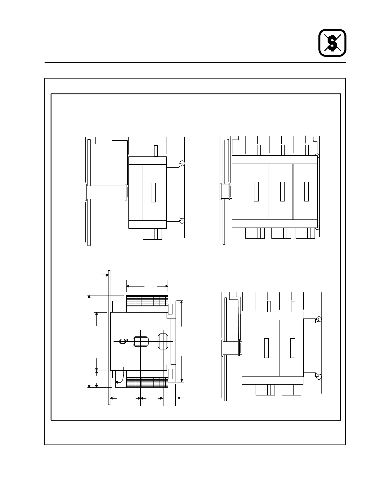
99” (2515mm)
68.5” (1740mm)
Suppy (AMU)
67.5” (1715mm)
Quick Disconnect
Exhaust Quick
63.5” (1613mm)
Disconnect
37.69” (957mm)
47.5” (1207mm)
top ofoven only
23.5” (597mm)
0” (0mm)
FRONT VIEW (VIB3240 - -- 1)
Maintenance
49.5” (1257mm)
63.68” (1618mm)
73.5” (1867mm)
top ofoven only
89.5” (2273mm)
93.5” (2375mm)
94.5” (2400mm)
99” (2515mm)
25.5” (648mm)
39.68” (1008mm)
Servicing
0” (omm)
15.68” (398mm)
1.5” (38mm)
VIB3240
8’ C EILING
0” (0mm)
FROM WALL
CLEARANCE
77” (1956mm)
40” (1016mm)18”
GAS
INPUT
(457mm)
*Ductwork should be terminated 99” (2515mm) above the finished floor (2” (51mm) above an 8’ ceiling). All other connections will be supplied with the hood.
(660mm
26” or 34.8”*
or
EXHAUST
883mm)
33.25”
(845mm)
19”
(483mm)
99” (2515mm)
86.5” (2197mm)
85.5” (2172mm)
SUPPLY
TOP VIEW
58” (1473mm)
14”
(356mm)
* 34.8” (883mm) for VIB3240-3, 26” (660mm) for VIB3240-1 or VIB3240-2
65.5” (1664mm)
81.5” (2070mm)
55.69” (1415mm)
top ofoven only
41.5” (1054mm)
31.69” (805mm)
17.5” (445mm)
FRONT VIEW (VIB3240 - -- 3) WITH CASTER CRADLES
0” (0mm)
FRONT VIEW (VIB3240 - -- 2)
Figure 18
29
Page 31

Servicing
Maintenance
99” (2515mm)
68” (1727mm)
Suppy (AMU)
Quick Disconnect
67” (1702mm)
Exhaust Quick
Disconnect
63” (1600mm)
47” (1194mm)
top of oven only
37.5” (953mm)
23.5” (597mm)
0” (0mm)
FRONT VIEW (VIB3855 - -- 1)
99” (2515mm)
92” (2337mm)
93” (2362mm)
72” (1829mm)
top of oven only
88” (2235mm)
48.5” (1232mm)
62.5” (1588mm)
39” (991mm)
25” (635mm)
15.5” (394mm)
1.5” (38mm)
0” (0mm)
VIB3855
8’ C EILING
0” (0mm)
FROM WALL
CLEARANCE
91.12” (2314mm)
55.12” (1400mm)
18”
*Ductwork should be terminated 99” (2515mm) above the finished floor (2” (51mm) above an 8’ ceiling). All other connections will be supplied with the hood.
(457mm)
16.75”
(425mm)
(737mm
29” or 32”*
Gas Input
or
Exhaust
813mm)
39.6”
(1006mm)
21”
(533mm)
Supply
TOP VIEW
73” (1854mm)
12.3”
(312mm)
99” (2515mm)
85.5” (2172mm)
84.5” (2146mm)
* 32” (813mm) for VIB3855-3, 29” (737mm) for VIB3855-1 or VIB3855-2
80.5” (2045mm)
64.5” (1638mm)
top of oven only
41” (1041mm)
55” (1397mm)
31.5” (800mm)
17.5” (445mm)
FRONT VIEW (VIB3855 - -- 3) WITH CASTER CRADLES
0” (0mm)
FRONT VIEW (VIB3855 - -- 2)
Figure 19
30
Page 32

99” (2515mm)
68” (1727mm)
Suppy (AMU)
Quick Disconnect
67” (1702mm)
Exhaust Quick
Disconnect
63” (1600mm)
37.5” (953mm)
47” (1194mm)
top of oven only
23.5” (597mm)
0” (0mm)
FRONT VIEW (VIB3870-1)
92” (2337mm)
93” (2362mm)
99” (2515mm)
Maintenance
25” (635mm)
39” (991mm)
48.5” (1232mm)
62.5” (1588mm)
72” (1829mm)
top of oven only
88” (2235mm)
Servicing
0” (0mm)
15.5” (394mm)
1.5” (38mm)
VIB3870
8’ C EILING
0” (0mm)
FROM WALL
CLEARANCE
70” (1780mm)
105.8” (2685mm)
18”
*Ductwork should be terminated 99” (2515mm) above the finished floor (2” (51mm) above an 8’ ceiling). All other connections will be supplied with the hood.
(457mm)
22.5”
(572mm)
33” or 36”
Gas Input
914mm)
(838mm or
39.6”
(1006mm)
21”
(533mm)
Supply
TOP VIEW
88” (2235mm)
12.3”
(312mm)
Exhaust
99” (2515mm)
85.5” (2172mm)
84.5” (2146mm)
* 36” (914mm) for VIB3870-3, 33” (838mm) for VIB3870-1 or VIB3870-2.
80.5” (2045mm)
64.5” (1638mm)
top of oven only
41” (1041mm)
55” (1397mm)
31.5” (800mm)
17.5” (445mm)
FRONT VIEW (VIB3870-3) WITH CRADLE CASTERS
0” (0mm)
FRONT VIEW (VIB3870-2)
Figure 20
31
 Loading...