

Page 1

UNIVERSAL HOLDING CABINET
SERVICE AND REPAIR MANUAL
BLODGETT OVEN COMPANY
www.blodgett.com
44 Lakeside Avenue, Burlington, Vermont 05401 USA Telephone (800) 331-5842, (802) 860-3700 Fax: (802)864-0183
PN 33954 Rev B (6/01)
Duplication of the information in this manual is prohibited without the consent of the Blodgett Service Department.
E 1998 --- G.S. Blodgett Corporation All rights reserved.
Page 2

TABLE OF CONTENTS
1. INTRODUCTION
Description 1 --- 1......................................................................
Specifications 1 --- 2....................................................................
2. OPERATION
Control Panel Descriptions 2--- 1.........................................................
Operator Mode 2 --- 2...................................................................
Timer Operation 2 --- 3..................................................................
Meal Selection 2 --- 4...................................................................
Clean Mode 2 --- 5......................................................................
Slot On/Off 2 --- 6.......................................................................
Displaying Slot Temperature Information 2--- 7.............................................
Operating Tips 2 --- 8...................................................................
Sequence of Operation 2 --- 9............................................................
3. PROGRAMMING AND CALIBRATION
Store Manager Programming 3--- 1......................................................
Product Selection for E ach Slot 3--- 1.................................................
Entering and Editing Product Information 3--- 6........................................
More Product Prompt Time Feature 3--- 11.............................................
Changing the Display Time 3--- 12.....................................................
Changing the Display Intensity 3--- 13..................................................
Service Programming and Calibration 3--- 14...............................................
To Access Service Programming 3--- 14................................................
Offset Calibration 3 --- 1 5.............................................................
Display Test Mode 3 --- 1 5............................................................
Timer Fast Test 3 --- 1 5...............................................................
Changing from _Fto_C 3 --- 1 9......................................................
Programming Alarms 3--- 20..........................................................
4. TROUBLESHOOTING
Troubleshooting Elements and Warning Alarms 4---1......................................
Troubleshooting Flow Diagrams 4---4....................................................
Troubleshooting a Locked Out Slot 4---10.................................................
Troubleshooting Sensor Alarms 4---11....................................................
Troubleshooting the Driver Board and Control 4--- 12........................................
i
Page 3

TABLE OF CONTENTS
5. PARTS REPLACEMENT
Element or Probe Assembly 5--- 1........................................................
Cooling Blower 5 --- 2...................................................................
Bezel Assembly 5 --- 3..................................................................
Membrane Switch 5 --- 4................................................................
LED Board 5 --- 4.......................................................................
Driver Board 5 --- 5.....................................................................
Temperature P r o b e 5 --- 5...............................................................
Mother Board 5 --- 5....................................................................
Bezel Gasket 5 --- 6.....................................................................
Chip Replacement 5 --- 7................................................................
6. TECHNICAL APPENDIX
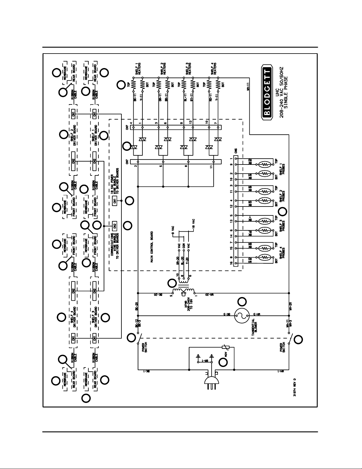
Schematic 6 --- 1.......................................................................
Wiring Diagram 6 --- 2...................................................................
Temperature P r o b e 6 --- 3...............................................................
ii
Page 4

CHAPTER 1
INTRODUCTION
Page 5

UHC
DESCRIPTION
The Blodgett Universal Holding Cabinet is a short
term holding device designed to maintain the
freshness of a variety of food product. The UHC
contains four product slots which can be controlled independently. Control panels are located
above each slot on both the front and rear of the
cabinet. All operator mode selections can be made
from either the front or rear display.
Power Switch --- controls power to the cabinet.
Product Slot --- holds up to three trays of product
per slot.
Control Panel --- indicates the holding time and
product selection for each tray position.
1/3 Size Product Tray --- designed for all grilled
products (meat, eggs, chicken). This tray maintains the product’s moisture.
Knockouts for
Double Stacking
1/2 Size Crumb Tray with Wire Rack --- d e s i g n e d
for fried products (crispy chicken, nuggets, fillet).
The tray keeps the fried crumbs from dropping
through the racks. It also allows moisture to escape leaving the outside of the product crispy.
Full Size Product Tray --- designed for bread products (biscuits a nd muffins). This tray allows a small
amount of moisture to escape.
Each Universal Holding Cabinet is shipped with
the following:
D
Equipment manual
D
PM card
D
Training video
D
Quick-reference guide
D
Cleaning brush
Power Switch
Product Slot
Control Panel
FIGURE 1
1 --- 1
Page 6

SPECIFICATIONS
INTRODUCTION
OVEN CLEARANCES
The following clearances must be available for servicing.
D
C a b i n e t b o d y s i d e s --- 2 2 ” ( 5 6 c m )
D
C a b i n e t b o d y b a c k --- 25 ” ( 6 4 c m )
ELECTRICAL SPECIFICATIONS
Electrical Specifications (per section)
KW Hz Vol ts Phase Amps
U.S. and Canadian installations
2.5/3.3 50/60 208/240 1 20
General Export installations
2.5/3.3 50/60 208/240 1 20
TABLE 1
Installation must conformwith local codes, or in the
absence of local codes, with the National Electrical
Code, ANSI/NFPA 70 --- Latest Edition and/or Canadian Electrical Code CSA C22.2 as applicable.
Wiring diagrams are located inside the right side
panel.
This appliance is equipped with a three-prong
grounding plug for your protection against shock
hazard and must be plugged into a properly
grounded three-prong receptacle. DO NOT cut or
remove the grounding prong from this plug.
CONTROL SPECIFICATIONS
Operating Voltage
Input Voltage 264 VAC maximum
Load Requirements
(heaters)
System Operating
Environment
Required Handling
Precautions
208 VAC +10/ ---15% or
240 VAC+10/--- 15%
50 or 60 Hz
177 VAC minimum
400 watt maximum at
240 VAC, resistive load,
8 heaters per cabinet max.
50-104_F(10-40_C) with
400 ft/minute airflow over
circuit board assemblies
Circuits contain sensitive
electronic components.
DO NOT ship or store
near strong electrostatic,
electromagnetic, magnetic or radioactive field.
CAUTION: Due to electrostatically sensitive
components. All technicians performing service
work must be grounded.
Grounding may be accomplished using a
grounding strap or other
suitable means. Connect
to another grounded unpowered piece of equipment. (ie. equipment other than the one you are
currently working on.)
1 --- 2
TABLE 2
Page 7

UHC
This page intentionally left blank.
1 --- 3
Page 8

CHAPTER 2
OPERATION
Page 9

UHC
CONTROL PANEL DESCRIPTIONS
1 1 12 2 25 4 3
UHC Front Control Panel
1 1 12 2 2
UHC Rear Control Panel
FIGURE 1
FRONT CONTROL PANEL
1. TIMER KEYS --- start and stop the timer associated with each tray position. The timer keys
also turn off audible alarms. There are three
timer keys on each front panel (left, center and
right).
2. DISPLA YS --- show product selection and hold
time for each tray position. The displays also
provide programming information in the program mode. There are three displays on each
front panel (left, center and right).
3. MENU KEY --- press to select meal transitions
(breakfast to lunch), clean mode operation
and to turn individual slots on or off. The menu
key also provides access to the program
mode.
4. TEMPERATURE/ENTER/PAGE KEY --- this key
has three separate functions.
D
Display slot temperature information
D
Enter operational changes
REAR CONTROL PANEL
NOTE: The rear panels are used for operational
functions only. All programming must be
performed from the front panels.
1. TIMER KEYS --- start and stop the timer associated with each tray position. The timer keys
also turn off audible alarms. There are three
timer keys on each front panel (left, center and
right).
2. DISPLA YS --- show product selection and hold
time for each tray position. There are three displays on each front panel (left, center and
right).
D
Select page parameters in program mode.
5. UP and DOWN ARROW KEYS --- press to increase/decrease variables or change selections.
2 --- 1
Page 10

OPERATOR MODE
OPERATION
The operator mode is the normal operating mode
of the controller when all slots are at the proper
temperature and no alarm conditions exist. Product information and hold time are displayed.
SLOT TEMPERATURE CONTROL
Each product selection has its own temperature
setpoint and product hold time. All product timers
run independently.
The slot temperature is controlled by the temperature setpoint of the left most product entry in each
slot as viewed from the front of the cabinet (side
with the On/Off switch). Product selections that
have a hold temperature different than the left most
SAUS
!.!.!
.
Use first timer
(highest intensity)
.
(medium intensity)
product selection will not be available for entry into
that slot’s configuration.
DISPLAY INFORMATION
In the operator mode the slot displays provide the
following information:
D
The product selection for each tra y location.
D
The hold time remaining (in minutes) for active
timers.
NOTE: An active timer alternately displays the
product selection and the time remaining.
Inactive timers display only product selection.
Active timer
Inactive timer
(lowest intensity)
12
.!.!.!.
Running dots (decimal points)
FIGURE 2
2 --- 2
Page 11
UHC
TIMER OPERATION
NOTE: If more than one tray of product is timing,
the tray with the least hold time remaining
is indicated by the Use First display.
Starting a timer
1. Press the TIMER KEY above t he desired tray
position to start the timer. The timer counts
down from a preset value and alternately displays product selection and the hold time remaining.
Stopping a timer
1. Press the TIMER KEY above the slot position
to turn off an active timer. The timer stops timing. The display changes to the inactive status.
Timing out
1. The time out alarm alerts t he operator that the
product hold time has expired. When the hold
SAUS
.!.!.!.
time remaining reaches zero an audible alarm
sounds and the display reads --- 0 0 --- .
NOTE: The audible alarm is indicated by a
modulating tone. A continuous tone
signals a warning alarm.
All other active displays in the cabinet switch to
the lowest intensity level until the audible alarm
is turned off.
2. Press the TIMER KEY to clear the timed out display and silence the alarm.
If other timers in the cabinet have timed out,
the audible alarm remains on until all timed out
displays are cleared.
3. When all timers are cleared, active timers return to normal status. The Use First status is
switched to the next timer with the least hold
time remaining.
45
!.!.!
.
SAUS
.!.!.!.
.
Display alternately indicates hold time and
product selection for active timers.
--- 0 0 ---
Press timer key to stop or silence a timer
Press timer key to start a timer
!.!.!
.
SAUS
.!.!.!.
.
Use First indication changes to the next active timer
FIGURE 3
2 --- 3
Page 12
MEAL SELECTION
OPERATION
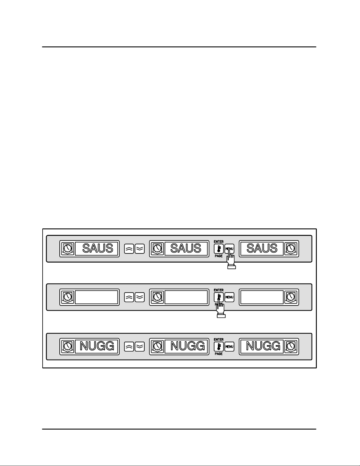
Selecting breakfast and lunch
NOTE: The following example is for selecting
breakfast. The same procedure applies for
selecting lunch.
1. Press the MENU KEY to change the product
selection of the slot from breakfast to lunch. All
displays are highlighted.
2. Press the ENTER KEY to activate the meal
selection. The displays switch to the inactive
mode.
NOTE: If the enter key is not pressed within
five seconds, the product selection returns to the breakfast meal selection.
Changing meal selections
Active slots with active timers will not change to the
new meal selection until the timer(s) are stopped
or time out and are reset. Active timers are stopped
by pressing the timer key.
If t h e product selection for the meal h a s a hold temperature different than the current meal, a high or
low temperature alarm is displayed to alert the operator that the hold temperature is being changed.
Should the high or low temperature condition remain for two or more minutes, an audible alarm
sounds. (See page 4--- 1 of the Troubleshooting
section.) To silence the alarm press any timer key.
This does not affect the timer operation unless the
timer key is pressed again. The display alternately
indicates the product selection and the alarm message until the slot temperature is within the preset
limits.
If no keys are pressed, the alarm message automaticallyresets when the slot temperature is within
the preset limits.
NUGG
Press menu key to display inactive
meal selection
NUGG NUGG
Press enter key to enter meal selection
and return to normal display mode
FIGURE 4
2 --- 4
Page 13
UHC
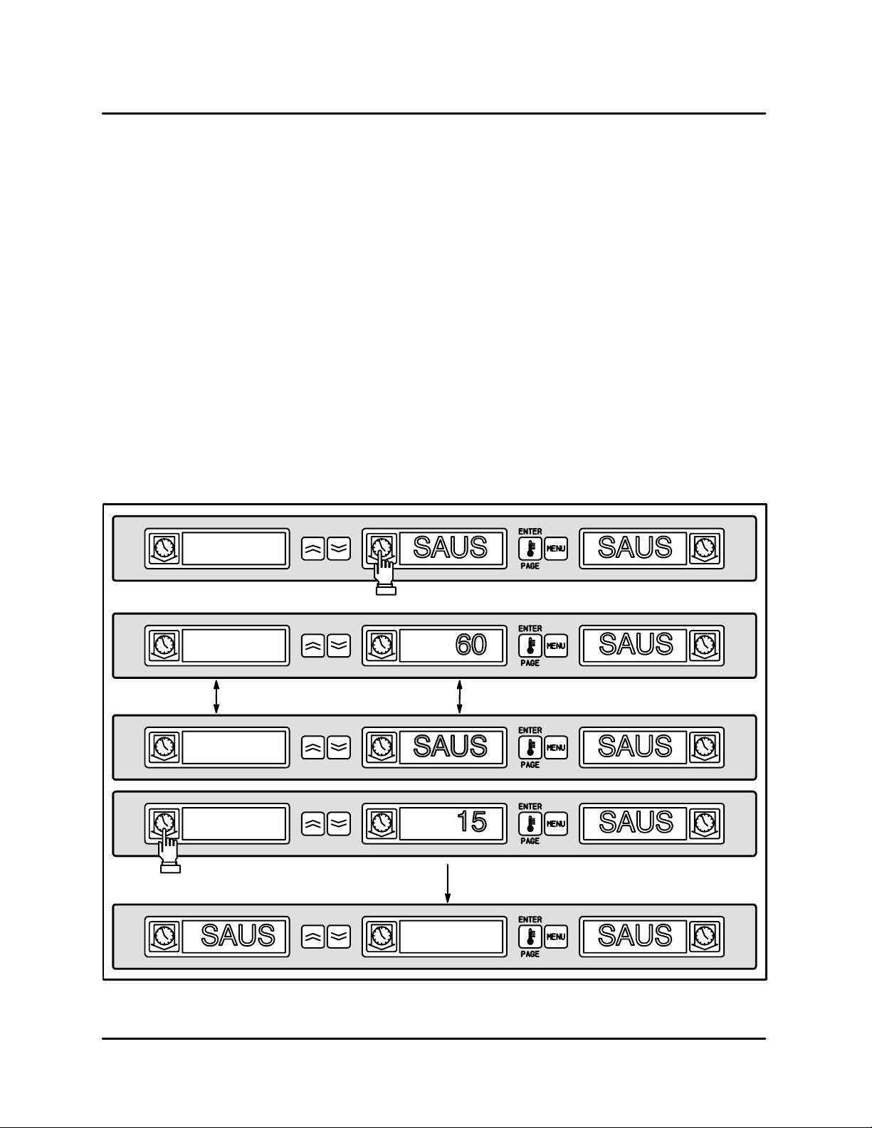
CLEAN MODE
The clean mode changes the temperature setpoint
of all slots in the cabinet to 125_F(52_C).
To s t a r t the clean mode
1. PresstheMENUKEYtoscrolltotheclean
mode message, CLN MODE.
2. Press the ENTER KEY to activate the clean
mode. All slots change to clean mode.
NOTE: If the enter key is not pressed within 5
seconds the control returns to the previous meal selection.
If the temperature is above 125_F(52_C), the
display alternately reads SLOT CLN MODE
CLN MODE
and NOT SAFE YET. The display reads SAFE TO
CLN when the slot is 125_F(52_C).
To exit clean mode
1. Press the MENU K E Y to display CLN MODE.
2. Press the ENTER KEY to exit the clean mode
and return to normal operation. The slot alternately displays SLOT TEMP LOW and the prod uct selection until the temperature is within the
normal operating limits.
NOTE: If the enter key is not pressed within 5
seconds the slot returns to the clean
mode.
Press menu key to scroll to clean
mode message
Press enter key to start clean mode
SAFE TO CLN
CLN MODE
To exit clean mode press menu key
to display clean mode message
EXIT CLN MODE
Press enter key to return to normal
display mode
FIGURE 5
2 --- 5
Page 14

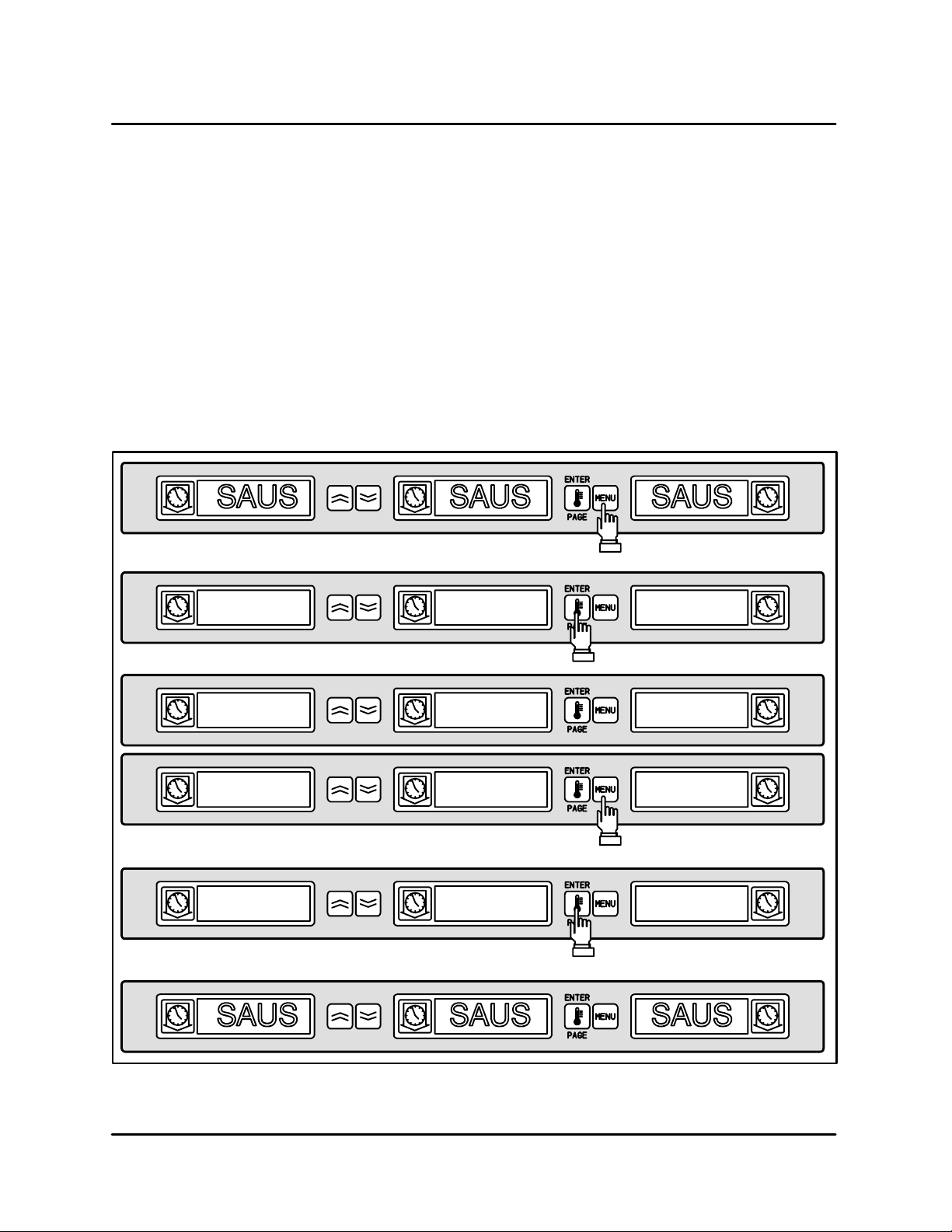
SLOT ON/OFF
OPERATION
To turn slot off
1. Press the MENU KEY to scroll to the slot off
message, TURN SLOT OFF .
2. Press the ENTER KEY to enter the selection.
The display reads SLOT IS OFF.
NOTE: If the enter key is not pressed within
five seconds the product selection returns to the operator mode.
TURN SLOT OFF
To turn slot on
1. Press the MENU KEY to scroll to the slot on
message, TURN SLOT ON.
2. Press the ENTER KEY to enter the selection
and return to the operator mode. The display
alternately reads SLOT TEMP LOW and the
product selection until the temperature is within normal operating limits.
NOTE: If the enter key is not pressed within
five seconds the slot returns to slot off
status.
Press menu key to scroll to slot off
message
Press enter key to turn slot off
SLOT IS OFF
SLOT IS OFF
Press menu key to scroll to slot on
message
TURN SLOT ON
Press enter key to turn slot on and return
to normal display mode
FIGURE 6
2 --- 6
Page 15

UHC
DISPLAYING SLOT TEMPERATURE INFORMATION
1. Press the TEMPERATURE KEY to scroll the following temperature information for each slot:
D
Top plate actual temperature
D
Bottom plate actual temperature
TOP TEMP 155
BOT TEMP 155
D
Top plate setpoint temperature
D
Bottom plate setpoint temperature
2. The display automatically returns to operator
mode if no key is pressed for five seconds.
Press temperature key to display top
plate temperature
Press temperature key to display
bottom plate temperature
Press temperature key to display top
plate setpoint temperature
TOP TSET 155
Press temperature key to display bottom
plate setpoint temperature
BOT TSET 155
Press temperature key to turn return to
normal display mode
FIGURE 7
2 --- 7
Page 16

OPERATING TIPS
OPERATION
Correct heat and moisture levels are important to
the proper operation of the UHC. There are no
doors in the cabinet. The trays act as doors, therefore it is important that they be positioned correctly.
The trays must be inserted to the stop line. The
stop line is clearly marked on the handle of all three
tray styles.
Product Slots
The UHC has four slots that can hold up to three
trays of product per slot.
Slot 1
Slot 2
Slot 3
Baked Products
Thefullsizetrayisdesignedtoholdallbakedproducts such as biscuits and muffins.
D
Use a UHC tray liner with the full size tray.
D
After biscuits have been removed from the biscuit oven, remove the wrapper and open the
cardboard box. Slide the biscuits onto the tray
liner.
D
Full size trays can hold up to 30 frozen biscuits,
20 scratch biscuits or 20 muffins.
Grilled Products
The 1/3 trayis designed to hold all grilled products.
D
Product should not be drained when picked up
from the grill.
D
Use a UHC tray liner with the 1/3 tray.
D
Product should be stacked when placed in the
lined 1/3 size tray. 10:1 and sausage patties
can be stacked up to six high. Eggs (except
scrambled), grilled chicken and 4:1 patties can
bestackeduptothreehigh.
D
Product should be placed towards the center
of the tray.
Slot 4
FIGURE 8
Fried Products
The 1/2 crumb tray with the wire rack is designed
to hold all fried products.
D
Product should be held in the wire rack which
is placed in the crumb tray.
D
UHC tray liners are not necessary when using
thewirerackforfriedproduct.
FIGURE 9
Production control charts
Laminated charts can be ordered through O’Brien
Budd, Inc. The ordering numbers are:
D
Breakfast UHC card #MCD 63102
D
Regular M enu UHC card # MDC 63102A
2 --- 8
Page 17

UHC
SEQUENCE OF OPERATION
COMPONENT REFERENCE
NOTE: Refer to FIGURE 10 page 2 ---10 for compo-
nent locations.
1. METAL OXIDE VARISTOR
2. DPST POWER SWITCH
3. TANGENTIAL BLOWER
4. TRANSFORMER 200-240V
5. HEATER TRIAC
6. HEATER ELEMENTS
7. SHELF PROBES
8. SHELF 1 DRIVER BOARD
9. SHELF 2 DRIVER BOARD
10. SHELF 3 DRIVER BOARD
11. SHELF 4 DRIVER BOARD
12. SHELF 1 FRONT DISPLAY ASSY.
13. SHELF 2 FRONT DISPLAY ASSY.
14. SHELF 3 FRONT DISPLAY ASSY.
15. SHELF 4 FRONT DISPLAY ASSY.
16. SHELF 1 REAR DISPLAY ASSY.
17. SHELF 2 REAR DISPLAY ASSY.
18. SHELF 3 REAR DISPLAY ASSY.
19. SHELF 4 REAR DISPLAY ASSY.
20. SHELF 1 FRONT MEMBRANE
21. SHELF 2 FRONT MEMBRANE
22. SHELF 3 FRONT MEMBRANE
23. SHELF 4 FRONT MEMBRANE
24. SHELF 1 REAR MEMBRANE
25. SHELF 2 REAR MEMBRANE
26. SHELF 3 REAR MEMBRANE
27. SHELF 4 REAR MEMBRANE
28. CN-1 CONNECTOR
29. CN-2 CONNECTOR
OPERATION
1. Apply power to the unit. The input voltage is
applied to t he DPST POWER SWITCH (2), the
TANGENTIAL BLOWER (3) and the primary
side of the 200-240V TRANSFORMER (4). The
input power is also applied to pins 2, 5, 8, and
11 of CN-7 on the mother board and to one
side of each HEATER ELEMENT (6) on WH-11.
2. 18VAC is applied to the mother board through
the secondary side of the TRANSFORMER (4)
between OR-20 a nd Y-20. 9VAC is applied to
the mother board from the secondary of the
TRANSFORMER (4) between BL-20 and
OR-20 and between BL-20 and Y-20. The mother board applies 18VAC to each shelf driver
board through the wire bundle at CN-1 (28)
while continuously exchanging operational
logic signals with each shelf driver board
through the wire bundle attached to CN-2 (29).
After the individual SHELF DRIVERS (8--- 11)
receive power and communications from the
mother board they send power and logic sig nals to its FRONT and REAR DISPLAY AS SEMBLIES (12--- 19) and their respective MEMBRANE SWITCH/DISPLAY DECALS (20--- 27).
3. The main control board uses the inputs from
the eight individual RTD PROBES (7) to determine if any of the eight HEATERS (6) need to
be energized to bring their respective shelf
sections to the proper temperature.
NOTE: The eight probes react independently
and sense temperature by resistance.
Refertothetableonpage6---3ofthe
Technical Appendix.
4. If the main control decides that an individual
shelf section is not at the correct temperature
it energizes the proper TRIAC (5) and sends
power t hrough CN-7 to the respective heater.
NOTE: If the main control senses that the tem-
perature of an individual shelf section
is much lower than the setpoint it will
pulse the voltage to the heater to maintain a consistent temperature with a
minimum overrun.
5. When the main control determines that all individual shelf sections are within their programmed setpoints it maintains these temperatures with a continual pulsing of the input
voltage to each shelf section independently.
NOTE: If the main control senses that a heater
is not performing to its programmed
specifications it can display a variety of
failure conditions. See page 4---1 of
the Troubleshooting section.
2 --- 9
Page 18
OPERATION
25
21
23
17
913
20
14
24
12
16
6
8
5
28
7
29
27
11
15
19
22
26
18
10
4
3
2
1
2
FIGURE 10
2 --- 1 0
Page 19

UHC
This page intentionally left blank.
2 --- 1 1
Page 20

CHAPTER 3
PROGRAMMING
AND CALIBRATION
Page 21

UHC
STORE MANAGER PROGRAMMING
PRODUCT SELECTION FOR EACH SLOT
Program mode is used to select the products for
each slot. All entries are made through PAGE and
MENU selections. Each slot has a page of configuration menus. The top slot in the cabinet is Slot 1.
D
The PAGE key selects the slot (1-4) pages.
D
The MENU key selects the configuration menu
items (meal and tray location).
D
The UP/DOWN arrow keys select the available
products for each meal.
PROG MODE
To e n t er P rogram M o d e
1. Press and hold the MENU KEY for at least five
seconds. The display reads PROG MODE .
To enter Page Selections
Each slot page (1-4) contains product selection for
each meal.
1. Press the PAGE KEY to scroll to the slot (1-4)
pages.
Press and hold menu key to enter
program mode
Press page key to scroll slot page
selections
SLOT 1
SLOT 2
SLOT 3
SLOT 4
FIGURE 1
Press page key to scroll slot page
selections
Press page key to scroll slot page
selections
Press page key to scroll slot page
selections
3 --- 1
Page 22

PROGRAMMING AND CALIBRATION
Meal Selection and Tray Position
1. Press the MENU KEY to scroll the meal and
tray position in the left and center displays. The
current product selection is indicated in the
right display.
SLOT 1 PAGE
BFST LEFT SAUS
Press menu to key to scroll
meal selection and tray position
Meal Selection Tray Position
Press menu to key to scroll
meal selection and tray position
BFST CENT SAUS
Meal Selection Tray Position
Press menu to key to scroll
meal selection and tray position
BFST RGHT SAUS
Meal Selection Tray Position
Press menu to key to scroll
meal selection and tray position
LNCH LEFT 10-1
Meal Selection Tray Position
Press menu to key to scroll
meal selection and tray position
LNCH CENT 10-1
Meal Selection Tray Position
Press menu to key to scroll
meal selection and tray position
LNCH RGHT 10-1
Meal Selection Tray Position
FIGURE 2
3 --- 2
Press menu to key to scroll
meal selection and tray position
Page 23

UHC
To enter Product Selection
1. Press the UP/DOWN ARROW KEYS to scroll
the available product selections for each meal
and tray position.
The product selection for the left tray position of
each meal determines the hold temperature for the
slot. Only products that have hold temperatures
within5_F(2.8_C) of the left most product selection
will be displayed for selection in the center and
right tray position. If the left most product selection
PRODUCT SELECTION
BFST LEFT SAUS
Press up/down arrow keys to
scroll product selections
BFST LEFT ROUN
Press up/down arrow keys to
scroll product selections
is changed, the center and right positions must be
reentered. If the product selection for an active timer is changed, the timer is automatically reset.
To exit Program Mode
1. Press and hold the MENU KEY for five seconds.
NOTE: The controller automatically exits the
program mode if no entries are made
for five minutes.
Product Selections
BFST LEFT FOLD
BFST LEFT SCRA
EXITING PROGRAM MODE
BFST LEFT SCRA
Press up/down arrow keys to
scroll product selections
FIGURE 3
Product Selections
Product Selections
Press and hold the menu key for
five seconds to exit program mode
3 --- 3
Page 24

PROGRAMMING AND CALIBRATION
Sample product selection cha nge
This example changes the lunch product selection
in the left position of slot 3 from 10- 1 to NUGG.
Since the hold temperature for NUGG is different
PROG MODE
SLOT 1
than 10-1, the center and right product selections
are cleared. Only items with hold temperatures
within 5_F(2.8_C) of the left product selection can
be entered for the center and right position.
Press menu to key for five seconds
to enter the program mode
Press page key to scroll slot page
selections
Press page key to scroll slot page
selections
SLOT 2
Press page key to scroll slot page
selections
SLOT 3
Press menu key to scroll meal
selection and tray position
BFST LEFT SAUS
Meal Selection Tray Position
Press menu key to scroll meal
selection and tray position
BFST CENT SAUS
Meal Selection Tray Position
Press menu key to scroll meal
selection and tray position
3 --- 4
Page 25

UHC
BFST RGHT SAUS
Meal Selection Tray Position
Press menu key to scroll meal
selection and tray position
LNCH LEFT 10-1
Meal Selection Tray Position
Press menu key to scroll meal
selection and tray position
LNCH LEFT 4-1
Press up/down arrow keys to scroll product selections
LNCH LEFT NUGG
Press and hold menu key for five
seconds to exit program mode
FIGURE 4
3 --- 5
Page 26

PROGRAMMING AND CALIBRATION
ENTERING AND EDITING PRODUCT INFORMATION
Changing or entering new product selections, hold
timer and temperature setting are password protected functions.
To enter the password
1. Press and hold the MENU KEY for five seconds. The display reads PROG MODE .
2. Press the ENTER/PAGE KEY to scroll to VIEW
PAGE.
3. Press the MENU KEY to select the security
lock, SECR LOCK.
4. Press the UP and DOWN ARROW KEYS to enter the security code 123.
ENTERING THE PASSWORD
5. Press ENTER/PAGE KEY..
A new product entry requires entry of:
D
the product name,
D
hold time,
D
hold temperature from 55-250_F (13-121_C),
D
meal selection,
The following example enters a new product,
named XXY, with a hold time of 25 minutes and hold
temperature of 180_F(82_C).
Press and hold menu key to enter
program mode
PROG MODE
Press enter/page key to scroll view page
VIEW PAGE
Press menu key to scroll to the
security lock
SECR LOCK 156
Press up/down arrow keys to enter password
SECR LOCK 123
FIGURE 5
3 --- 6
Page 27

UHC
ENTERING THE PRODUCT NAME
SECR LOCK 123
EDIT PAGE SAUS
PROD NAME .
Press page key to scroll to the edit page
Press menu key to scroll to an
unused product (blank) mnenonic
Press up arrow key to
scroll to the letter X
NOTE: The decimal point indicates which dis
play segment is being entered.
PROD NAME X.
Press down arrow key to scroll to the next display segment
PROD NAME X.
Press up arrow key to scroll to the letter X
PROD NAME XX.
Press down arrow key to scroll to the next display segment
PROD NAME XX.
Press up arrow key to scroll to the letter Y
PROD NAME XXY.
FIGURE 6
3 --- 7
Page 28

ENTERING THE PRODUCT HOLD TIME
PROD NAME XXY.
TIME PAGE XXY
XXY TIME 20
PROGRAMMING AND CALIBRATION
Press page key to scroll to the time page
Press menu key to scroll to product
time selection
Press up/down arrow key to change time to 25 minutes
XXY TIME 25
FIGURE 7
3 --- 8
Page 29

UHC
ENTERING THE PRODUCT HOLD TEMPERATURE
XXY TIME 25
TEMP PAGE XXY
XXY Ttop 155
Press up/down arrow key to change top plate temperature
XXY Ttop 180
Press page key to scroll to the temp page
Press menu key to scroll to product
top plate temperature selection
Press menu key to scroll to product
bottom plate temperature selection
XXY Tbot 155
Press up/down arrow key to change bottom plate temperature
XXY Tbot 180
FIGURE 8
3 --- 9
Page 30

ENTERING MEAL USAGE
XXY Tbot 180
MEAL PAGE XXY
XXY MEAL ALL
XXY MEAL BFST
PROGRAMMING AND CALIBRATION
Press page key to scroll to the meal page
Press menu key to scroll to product
meal selection
Press up/down arrow keys to select BFST
FIGURE 9
3 --- 1 0
Page 31

UHC
MORE PRODUCT PROMPT TIME FEATURE
A cook more time may be entered for each product
type that will alert the operator to cook more product before t he holding time reaches zero. When the
product timer equals the cook time the audible
alarm will chirp for 3 seconds and the display message will alternately display PRODUCT NAME, TIM-
ER TIME, COOK and MORE until the timer times
out. If more than one tray of a product type is active
the cook more alarm will not occur until all active
timers reach the cook time.If a position is indicating, COOK MORE and another timer of the same
product is started, the COOK MORE message will
be cleared. During transition from breakfast to
lunch the COOK MORE indication is disabled. Use
the following procedure to change or enter the
cook time of a product svelection:
DEFAULT SELECTIONS FOR THE PROMPT TIME
MNEMONICS
Left Center Right*
COOK PAGE Cook Page
SAUS COOK 4 Product 1 Cook Time 0 --- 3 0 M i n u t e s 3
1. Press and hold the menu key for 5 seconds.
2. Pressthepagekeytoscrolltoviewpage.
3. Press the menu key to scroll to the security
lock.
4. Press the up and down arrow keys to enter the
manager security code: 3 3 1.
5. Press the page key to scroll to cook page.
6. Press the menu key to scroll to product selection.
7. Press the up and down arrow keys to increase
or decrease the prompt time (in minutes) to
cook more product.
8. When complete, press and hold the menu key
for 5 seconds to return to normal operation.
Description Available
Settings Level
Access
ROUN COOK 4 Product 2 Cook Time 0 --- 3 0 M i n u t e s 3
FOLD COOK 3 Product 3 Cook Time 0 --- 3 0 M i n u t e s 3
SCRA COOK 3 Product 4 Cook Time 0 --- 3 0 M i n u t e s 3
RBAC COOK 0 Product 5 Cook Time 0 --- 3 0 M i n u t e s 3
CBAC COOK 1 Product 6 Cook Time 0 --- 3 0 M i n u t e s 3
MUFF COOK 3 Product 7 Cook Time 0 --- 3 0 M i n u t e s 3
BISC COOK 22 Product 8 Cook Time 0 --- 3 0 M i n u t e s 3
BURR COOK 0 Product 9 Cook Time 0 --- 3 0 M i n u t e s 3
1 0 --- 1 COOK 2 Product 10 Cook Time 0 --- 3 0 M i n u t e s 3
4 --- 1 COOK 4 Product 11 Cook Time 0 --- 3 0 M i n u t e s 3
GRCK COOK 5 Product 12 Cook Time 0 --- 3 0 M i n u t e s 3
NUGG COOK 5 Product 13 Cook Time 0 --- 3 0 M i n u t e s 3
FISH COOK 5 Product 14 Cook Time 0 --- 3 0 M i n u t e s 3
McCK COOK 7 Product 15 Cook Time 0 --- 3 0 M i n u t e s 3
NOTE: The right display gives the time in minutes.
3 --- 1 1
Page 32

CHANGING THE DISPLAY TIME
PROGRAMMING AND CALIBRATION
The rate at which an active timer alternately displays product selection and hold time may be adjusted as follows:
1. Enter the manager programming security
code. See page 3 ---6.
2. PresstheMENUKEYtoscrolltoproductdisplay time, PROD TIME.
3. Press the UP and DOWN ARROW KEYS to
change the product display time.
CHANGING THE DISPLAY TIME
SECR LOCK 123
Press and hold menu key scroll to PROD TIME
PROD TIME 10
Use the arrow keys to change product display time
4. PresstheMENUKEYtoscrolltotimerdisplay
time, TIMR TIME.
5. Press the UP and DOWN ARROW KEYS to
change the timer display time.
6. Press and hold the MENU K EY for five seconds
to return to normal operation.
TIMR TIME
Press menu key to scroll to TIMR TIME
TIMR TIME 10
Use the arrow keys to change timer display time
Press and hold the menu key to return to normal operation
FIGURE 10
3 --- 1 2
Page 33

UHC
CHANGING THE DISPLAY INTENSITY
The brightness of each of t he three intensity levels
used for product status may be adjusted as follows:
1. Enter the manager programming security
code. See page 3 ---6.
2. PresstheMENUKEYtoscrolltodisplayintensity level. The display reads DISP IntX.There
are three display intensity levels available.
Level #
1 (dimmest) Int1 10--- 25 10
2 (mid-level) Int2 10--- 25 10
3(brightest) Int3 67-100 100
CHANGING THE DISPLAY TIME
Display Range Default
TABLE 1
SECR LOCK 123
3. Press the UP and DOWN ARROW KEYS to
change the intensity level.
4. Press and hold the MENU K EY for five seconds
to return to normal operation.
Press and hold menu key scroll to DISP Int1
DISP Int1 10
Use the arrow keys to change product display intensity
DISP Int1 20
Press and hold the menu key to return to normal operation
FIGURE 11
3 --- 1 3
Page 34

PROGRAMMING AND CALIBRATION
SERVICE PROGRAMMING AND CALIBRATION
THE FOLLOWING PROGRAMMING AND CALIBRATION INFORMATION IS FOR AUTHORIZED
SERVICE PERSONNEL ONLY.
TO ACCESS SERVICE PROGRAMMING
Service programming is password protected. Use
the following procedure to enter the password and
access service programming (level 3 programming).
ENTERING THE PASSWORD
PROG MODE
1. Press and hold the MENU KEY for five seconds.
2. Press the ENTER/PAGE KEY to scroll to VIEW
PAGE.
3. PresstheMENUKEYtoscrolltothesecurity
lock, SCR LOCK.
4. Press the UP and DOWN ARROW KEYS to enter the security code 247 or 331.
5. Press ENTER/PAGE KEY.
Press and hold menu key to enter
program mode
Press enter/page key to scroll view page
VIEW PAGE
Press menu key to scroll to the
security lock
SECR LOCK 156
Press up/down arrow keys to enter password
SECR LOCK 331
Use 331 or 247
FIGURE 12
3 --- 1 4
Page 35

UHC
OFFSET CALIBRATION
The offset value is the difference between the setpoint and the actual temperature. If the actual temperature is lower than the setpoint a n egative offset
is needed. If the actual temperature is higher than
the setpoint a positive offset is needed.
Use the surface probe to compare the top a nd bottom t emperatures to the setpoint value of 155_F
(68_C). Takeall measurements from the s lot center
position. Record the value. Repeat for all slots. If
the actual temperature varies from the setpoint by
¦
5_F(3_C) adjust the temperature offset as follows:
1. After accessing the service level programming, press the ENTER/PAGE key to scroll to
the slot number requiring adjustment.
NOTE: It is possible to access all slots from
any display.
2. Press the MENU key to advance to top or bottom of offset selection. Use the ARROW keys
to select the offset value. Press the ENTER k ey
to advance to the next slot. Repeat for all slots.
3. Press the MENU key for five seconds to exit
service programming.
NOTE: It is not necessary to exit the program-
ming mode if you wish to advance to
Display Test or Timer Test.
plays have been checked, turn the unit off and
back on again to exit the display test mode.
4. After verifying all slot display segments illuminate, press the ARROW KEY to stop the test.
The display reads DISPLAY TEST OFF.
5. Press the MENU key for five seconds to exit
service programming.
NOTE: It is not necessary to exit the program-
ming mode if you wish to advance to
the Timer Test.
TIMER FAST TEST
This test changes the timing on the TIMER KEYS
from minutes to seconds t o allow for quick test of
the timer keys. Access service level programming
to execute the timer test.
1. Press the ENTER/PAGE key to scroll to TEST
PAGE.
2. Press the MENU KEY to scroll to FAST TEST
OFF.
3. Press the ARROW KEY to toggle to FAST TEST
ON.
4. It is necessary to exit the service programming
level to test the timer keys. Press the MENU
KEY for five seconds to exit service programming and test the timer keys.
DISPLAY TEST MODE
The display test verifies all display segments are
operational.
NOTE: Executing the display test requires access to
level 5 programming. Contact Blodgett Service to acquire the necessary password.
1. Press the ENTER/PAGE key to scroll to TEST
PAGE.
2. Press the MENU KE Y to scroll to DISPLAY TEST
OFF.
3. Press and hold the bottom two outside timers
until the displays change. All segments should
illuminate and stay lit to give the operator time
to check both sides of the UHC. After the dis-
5. Press any TIMER KEY to activate and verify the
timer count down while in seconds mode. The
timer counts down a nd an alarm sounds. To silence the alarm press the TIMER KEY.
6. To cancel TIMER FAST TEST re-enter the service level programming. See page 3 ---14.
7. Press the ENTER/PAGE key to scroll to TEST
PAGE.
8. Press the MENU KEY to scroll to FAST TEST
ON.
9. Press the MENU KEY to toggle to FAST TEST
OFF.
10. Press the MENU KEY for five seconds to exit
the service level programming.
3 --- 1 5
Page 36

OFFSET CALIBRATION
SLOT #
Press the enter key to scroll to the slot # requiring offset calibration
TOP OFST 0
TOP OFST 10
BOT OFST 0
PROGRAMMING AND CALIBRATION
Press the menu key to advance to top offset display
Use arrow keys to select offset value
Press the menu key to advance to bottom offset display.
Press the Enter/Page key to advance control to next slot
BOT OFST 0
Press the menu key for five seconds to exit service programming
FIGURE 13
3 --- 1 6
Page 37

UHC
DISPLAY TEST
TEST PAGE
Press the enter key to scroll to the display test
DISP TEST OFF
Press the menu key to advance to DISP TEST OFF
DISP TEST ON
Press the arrow keys to begin the test
Segments light individually
DISP TEST OFF
Press the arrow keys to end the test
Press the menu key for five seconds to exit service programming
FIGURE 14
3 --- 1 7
Page 38

PROGRAMMING AND CALIBRATION
TIMER FAST TEST
TEST PAGE
Press the enter key to scroll to the display test
FAST TEST OFF
Press the menu key to advance to FAST TEST OFF
FAST TEST ON
Press the arrow keys to toggle to FAST TEST ON
FAST TEST ON
Press the menu key for 5 seconds to exit service programming and test timer keys
Press any timer key to activate and verify the timer count down while
in seconds mode. Press the menu key for 5 seconds to re-enter the
program mode. Access the service level programming.
TEST PAGE
Press the enter key to scroll to TEST PAGE.
FAST TEST ON
Press the menu key to advance to FAST TEST ON
FAST TEST OFF
Press the arrow keys to toggle to FAST TEST OFF
Press the menu key for five seconds to exit service programming
FIGURE 15
3 --- 1 8
Page 39

UHC
CHANGING FROM _FTO_C
The following changes the temperature units from
_Fto_C.
1. Enter the service programming security code.
Seepage3---14.
2. Press the MENU KEY to scroll to display units.
CHANGING TEMPERATURE UNITS
SECR LOCK 331
Press and hold menu key to scroll to display units
DISP UNIT F
Press arrow keys to toggle units
DISP UNIT C
3. Press the UP and DOWN ARROW KEYS to
change from _Fto_C.
4. Press and hold the MENU K EY for five seconds
to return to normal operation.
Press menu key for 5 seconds to return to normal operation
FIGURE 16
3 --- 1 9
Page 40

PROGRAMMING ALARMS
PROGRAMMING AND CALIBRATION
FOOD AND DRUG ADMINISTRATION (FDA)
ALARM
The FDA alarm indicates the slot temperature is below the FDA temperature setpoint (140_F) for a
time greater than the FDA time setting.
1. Enter the service programming security code.
Seepage3---14.
2. Press the MENU KEY to scroll to FDA PAGE.
FDA ALARM
SECR LOCK 331
Press and hold menu key to scroll to the FDA page
FDA PAGE
Press the Enter/Page key to advance to the FDA time
3. Press the ENTER key to advance the control.
Use the ARROW keys to enter FDA time from
0-5 minutes. The default is 2 minutes. Press the
ENTER k ey to advance the control.
4. Use the ARROW keys to enter FDA temperature from 55-140_F. The defau lt is 140_F. P r e s s
the ENTER key to advance the control.
5. Press and hold the MENU key to exit programming.
FDA TIME 2
Use the arrow keys to enter FDA time from 0-5 minutes
FDA TIME 3
Press Enter/Page key to advance control
FDA TEMP 140
Use the arrow keys to enter FDA temperature from 55-140_F
Press Enter/Page key to advance control
FIGURE 17
3 --- 2 0
Page 41

UHC
HI AND LOW TEMPERATURE ALARMS
If the slot temperature is above or below the preset
limits for a product selection, the control enters the
high or low alarm condition. The alarm setpoints
can be programmed from the ALRM PAGE. They
are entered as _F offsets from the product setpoint.
The default settings are 10_F.
NOTE: When switching menus or products the
temperature alarm is displayed if the new
product or menu requires a holding temperature outside of the current alarm band.
If the condition remains for two or more
minutes an audible alarm sounds. Press
any timer key to silence the alarm. The display returns to normal when the new hold
temperature has been reached.
1. Enter the service programming security code.
Seepage3---14.
2. Press the MENU KE Y to scroll to ALRM PAGE.
3. Press the ENTER KEY to advance the control.
The display reads ALRM ENBL ON.
NOTE: Selecting ALRM ENBL OFF disables
the visual and/or audible product
alarms for all slots.
4. Use the ARROW KEYS to toggle bewteen off
and on. Press the MENU KEY to advance the
control.
5. The display reads ALRM LoSP X. Use the ARROW KEYS to enter the desired low temperature alarm from 1 -10_F. P r e s s t h e M E N U K E Y
to advance the control.
6. The display reads ALRM HiSP X. Use the ARROW KEYS to enter the desired high temperature alarm from 1 -10_F. P r e s s t h e M E N U K E Y
to advance the control.
7. The display reads ALRM TIME X. The alarm
time allows an alarm condition to exist for up to
5 minutes before activating the audible alarm.
The default setting is 2 minutes.
Use the ARROW KEYS to enter the desired
alarm time from 0-5 minutes. Press the ENTER
KEY to advance the control.
8. Press and hold the MENU key to exit programming.
HIGH AND LOW TEMPERATURE ALARM
SECR LOCK 331
Press and hold menu key to scroll to the alarm page
ALRM PAGE
Press the Enter/Page key to advance the control
ALRM ENBL ON
ALRM ENBL ON
Use the arrow keys to toggle from ON to OFF
Press Menu key to advance control
3 --- 2 1
Page 42

HIGH AND LOW TEMPERATURE ALARM
ALRM LoSP 10
ALRM LoSP 10
Press the Enter/Page key to advance the control
ALRM HiSP 0
ALRM HiSP 10
PROGRAMMING AND CALIBRATION
Use the arrow keys to enter desired low temperature alarm
(the range is 1-10 with a default of 10)
Use the arrow keys to enter desired high temperature alarm
Press the Menu key to advance the control
ALRM TIME 0
Use the arrow keys to enter alarm time
ALRM TIME 2
Press the Enter/Page key to advance the control
ALRM PAGE
Press and hold the menu key to exit programming
FIGURE 18
3 --- 2 2
Page 43

UHC
This page intentionally left blank.
3 --- 2 3
Page 44

CHAPTER 4
TROUBLESHOOTING
Page 45

UHC
TROUBLESHOOTING ELEMENTS AND WARNING ALARMS
CAUTION: Due to electrostatically sensitive
components. All technicians performing service work must be grounded. Grounding may
be accomplished using a grounding strap or
other suitable means. Connect to another
grounded unpowered piece of equipment. (ie.
equipment other than the one you are currently
working on.)
During initial heat from a cold start, the unit applies
full voltage to the elements. A s the shelf approaches the setpoint temperature, the control
pulses the output of the elements. This allows for
an accurate set point response with minimum temperature overrun.
NOTE: The control also pulses output during nor-
mal operation to provide an even temperature response.
To Troubleshoot an Element
1. Verify offset calibration. Refer to page 3--- 15. If
correct continue with step 2.
2. Attach an amp clamp to the input. Observe the
steady amp draw during the initial startup and
the subsequent pulsing of this input at temper atures close to set point.
The main control applies voltage to the element assemblies by way of a TRIAC solid state device. This
circuit normally fails in the closed position and can
result in an overheat condition. If the elements do
not receive the pulse input, the main control is de-
fective. To replace a defective element, the upper
and lower portion of the shelf must be replaced
whichever is defective.
Several w arning alarms can result from a defective
element:
D
High and low temperature alarm
D
FDA alarm
D
Sensor alarm
D
Rise time alarm
If an alarm conditions occurs, a display alarm appears. An audible alarm may sound depending on
the alarm condition. Press the timer key to silence
the audible alarm. Timers cannot be started w hen
aslotisinanalarmcondition.
HI AND LOW TEMPERATURE ALARM
If the slot temperature is above or below the preset
limits for a product selection, the controller enters
the high or low alarm condition. The display reads
either SLOT TEMP HIGH or SLOT TEMP LOW.
1. An audible alarm sounds if the alarm condition
remains for two or more minutes.
NOTE: The low temperature audible alarm is inhib -
ited at power up. The SLOT TEMP LOW
message is displayed alternately with the
product selection until the slot is within the
preset limits.
HIGH/LOW TEMPERATURE ALARM
SLOT TEMP LOW
SLOT TEMP HIGH
Press any timer key to silence audible alarm
Press any timer key to silence audible alarm
FIGURE 1
4 --- 1
Page 46

TROUBLESHOOTING
FOOD AND DRUG ADMINISTRATION (FDA)
ALARM
The FDA alarm indicates the slot temperature is below the preset limit to hold the product. The audible
alarm sounds and the display reads TEMP UNDR
FDA. Active timers are automatically reset.
1. To turn off the audible alarm press any TIMER
KEY. The alarm message remains until the slot
temperature is within the preset limits. If no
keys are pressed the audible and visual alarm
remain.
See page 4--8 for troubleshooting.
FDA ALARM
SENSOR RANGE ALARM
The sensor fail alarm indicates a sensor tempera ture value above or below the operating limits of
the slot, 50--- 250_F (10-121_C).
1. To turn off the audible alarm press any TIMER
KEY. The alarm message is displayed until the
slot temperature is within the operating limits.
2. Press the temp/enter key to display the error
message HHHH or LLLL. HHHH indicates high
resistance, high temperature or open/shorted
probe. LLLL indicates low resistance, low temperature or open/shorted probe. Measure the
resistance of the probe, see page 5 ---5.
3. Scroll through the menu key until TURN SLOT
OFF is displayed. Press the enter k ey within
five seconds.
Service is required to correct a sensor alarm.
Refer to the flow diagrams in this chapter f or
troubleshooting.
TEMP UNDR FDA
SENSOR RANGE ALARM
SENS ALRM
Press any timer key to silence audible alarm
Press any timer key to silence audible alarm
FIGURE 2
4 --- 2
Page 47

UHC
RISE TIME ALARM
Therisetimealarmindicatesthattheslottemperature failed to reach operating temperature within
the preset time limits of the system at power up.
The system measures the time that each plate
takes to go from 100--- 125_F. If this time is greater
than 15 minutes the alarm is activated and SLOT
RISE RATE is displayed.
1. To turn off the audible alarm press any TIMER
KEY.
Service is required to correct a rise time alarm.
See page 4--8 for troubleshooting.
RISE TIME ALARM
SLOT RISE RATE
Press any timer key to silence audible alarm
SLOT RISE RATE
Use the following procedure to view the rise times
for each plate:
1. Press and hold the MENU key to enter the program mode.
2. PressthePAGEkeytoscrolltotheTESTPAGE.
3. Press the MENU key to scroll the time recorded
foreachslotatstartup.
Press any menu key to enter the program mode
TEST PAGE
Press any menu key to scroll the recorded rise times
RATE TOP1 12:00
FIGURE 3
4 --- 3
Page 48

TROUBLESHOOTING FLOW DIAGRAMS
Problem:
Unit fails to power up.
TROUBLESHOOTING
Verify input power
to terminal block
Yes
Turn on power switch.
Verify blower operation
and power on primary
transformer
Yes
Is there voltage on the
secondary transformer?
Yes
Replace main board.
Problem:
Segment out in display.
Enter the display test
mode. See page 3 ---15.
Verify faulty segment
location. Swap front and
rear display driver cables.
No
No
No
Check
branch circuit
Replace
power switch
Replace transformer.
Leave secondary wiring disconnected.
Verify voltage on secondary transformer.
Isolate any shorts between transformer leads.
Replace effect ed components
No
Replace the driver board.
Is the segment still out?
Yes
Visually and electrically
check the suspect
display cable.
Is the cable ok?
Yes
Replace the display.
No
Replace the display cable.
FIGURE 4
4 --- 4
Page 49

UHC
Problem:
Unit does not heat
Is the unit plugged in?
Yes
Is the power switch on?
Yes
Is the breaker on? Turn breaker on
Yes
displayoneachshelf
Yes
Disconnect OR-20, BL-20 & Y-20 from the main board.
Is there approx. 18V output from the secondary of the
Is there approx. 9V output from the secondary of the
transformerbetweenBL-20&OR-20andBL-20&Y-20?
Reconnect OR-20, BL-20 &
Y-20 to the main board.
Is there approx. an 18V and
9V on the secondary?
No
No
No
NoIs there an illuminated
transformer between OR-20 & Y-20?
Yes
Yes
Plug unit in
Turn swit c h on
primary of the transformer?
Yes
NoIs 208 or 240V applied to the
Disconnect CN -1 (AC power
No
in) to each driver board.
Is there approx. 18V and 9V
on the main board?
Yes
Check power switch for failure
and wires from power switch to
primary of transformer for
continuity. Replace if necessary.
No
Replace the
transformer
No
Replace the
main board.
Is the heating problem
on all shelves?
Yes
Replace the
mother board
Replace the
main board
Is the resistance value of the probe correct
No
for the effected shelf (see TABLE 1 on
page 6---3 of the Technical Appendix)
Successively plug in driver board no 4, 3, 2 & 1. Verify
the secondary voltage at each step. If the secondary
voltage is lost, replace effected driver board.
Yes
Visually and electrically check RTD
and heater harness. Are they ok?
Yes
Is there input voltage (208 or 240)
applied to the effected element?
Yes
Replace the effected shelf assembly
FIGURE 5
4 --- 5
No
No Replace effected
No Replace the
Replace the
shelf assembly
harness
motherboard
Page 50

Problem:
An individual shelf display will not
change from breakfast to lunch or
will not allow the operator to set
or reset the timers.
TROUBLESHOOTING
Is the problem on
all three display
sections?
Yes
Are ribbon cable connections
from the display to the shelf
driver connected to their ap-
propriate driver board?
No
membrane to the
membrane switch
Are connections
from the control
LED display
proper and in
good condition?
Yes
Replace control
assembly.
Problem fixed.
Done
Connect the ribbon
No
cables to their
appropriate driver
No
board.
Clean or reinstall
ribbon connection.
Problem still exists.
Replace LED
display assembly
Problem fixed.
Done
Problem still exists.
Replace shelf
driver board.
Done
Yes
Replace LED
display assy.
Problem fixed.
Done
Problem still exists.
Replace the
driver board.
Done
FIGURE 6
4 --- 6
Page 51

UHC
Problem:
An individual shelf is in
an overheat or
underheat situation.
Is the resistance vs.
temperature on the
probe correct?
R e f e r t o p a g e 5 --- 5 f o r
procedure.
(see TABLE 1 on page
6 --- 3 o f t h e
Technical Appendix for
conversions)
Yes
No
Replace shelf assembly .
Does the input voltage
to the element cycle on
and off and pulse when
close to set point?
Yes
Replace
shelf assembly.
No
Is the programming
correct for this shelf?
(see Programming and
Calibration section)
Yes
Replace the
main board.
No
Correct the programming.
(see Programming and
Calibration section)
FIGURE 7
4 --- 7
Page 52

Problem:
Unit displays
sensor alarm.
Is the resistance vs.
temperature on the
probe correct?
R e f e r t o p a g e 5 --- 5 f o r
procedure.
(see TABLE 1 on page
6 --- 3 o f t h e
Technical Appendix for
conversions)
Yes
Does the resistance of
the probe and harness
approx. match TABLE 1
o n p a g e 6 --- 3 of t h e
Technical Appendix?
Yes
No
No
TROUBLESHOOTING
Replace the
shelf assembly.
Replace the
RTD harness.
Replace the
mother board.
Problem:
Unit displays
FDA or rise time alarm
Is the effected element
receiving 208 or 240
input voltage?
Yes
Bad probe or heater.
Replace the shelf
assembly.
No
Is the wiring harness
between the element and
mother board correct?
Yes
Replace the
mother board.
No
Correct the wiring.
FIGURE 8
4 --- 8
Page 53

UHC
Problem:
Keypad Timer, Enter/
Page or Menu keys
not working
Press problem key to
verify fa ult.
Is audible click heard?
Yes
Problem:
Keypad Arrow keys
not working
Enter service level
programming.
( S e e p a g e 3 --- 1 4 )
Press problem key to
verify fa ult.
Is audible click heard?
Yes
Swap suspect display
cable to same position
No
on different driver
board.
Press problem key. Is
audible click heard?
Yes
Replace driver board.No problem.
Swap faulty display cable
No
to same position on dif-
ferent driver board.
Press problem key. Is au-
dible click heard?
Yes
Replace membrane
No
switch.
Press problem key.
Is audible click
heard?
Yes
Problem fixed.
Done
No
No
Replace membrane
switch.
Press problem key.
Is audible click heard?
Yes
Replace
ribbon cable.
Replace driver board.No problem.
FIGURE 9
4 --- 9
Replace driver board.
Page 54

TROUBLESHOOTING A LOCKED OUT SLOT
TROUBLESHOOTING
1. Remove the rear ribbon cable from the driver
board.
If the front membrane starts to work, you have
now isolated the problem to one of three of the
rear components.
If the front is still locked up then remove the
front ribbon and try using the rear timers.
If they workthen you have isolated the problem
to one of three front components.
2. Before replacing the membrane switch,
Plug the new membrane into the display board
and try it in your hand. If it continues to lock up
then the problem is, in either the ribbon cable,
or the display board.
4 --- 1 0
Page 55

UHC
TROUBLESHOOTING SENSOR ALARMS
The following is a test procedure to be used on the
UHC-1 cabinet to determine the cause for many of
the sensor alarms we are experiencing. You will
need the probe resistance chart, found on page
6--- 3 to perform the following tests.
1. Determine the slot experiencing the “SENSOR
ALARM”.
2. Determinetheplatecausingthealarm.Todo
this you need to press t he ENTER key 4 times
in succession and read the displays.
A.) Push ENTER key once display reads: TOP
ACT ** HHHH.
B.) Push ENTER key again display reads: BO -
T ACT 200.
C.) PushENTER key again display reads: TOP
SET 200.
D.) Push ENTER key again display reads:
BOT SET 200.
This has now determined that the ”SENSOR
ALARM” is being caused by a high probe re sistance reading. (This example is indicative of
a potential probe problem on the top plate of
the slot experiencing the alarm).
3. Using a Pyrometer get the actual temp. of the
plate in question This is the temp you will be
referencing.
4. Remove the probe harness from the mother
board and get the resistance reading from the
correct probe leads (reference the schematic
on page 6 ---1). The resistance value a nd temperature should match according to the chart.
If the resistance reading did not coincide
proceed to STEP 5.
If the resistance coincides with the actual temp
the problem is either in the harness connection
or the mother board. Before replacing the
mother board check all the pins in the connec-
tor, reinstall the harness to the board, take a
tooth pick, snap it in half and insert each piece
into the back of the probe wires. Check the
temp displays again to see if the TOP ACT coincides with the actual temperature. If so the
problem was in the connection and the probe
harness should be replaced. If you still have
HHHH the problem is in the mother board and
it should be replaced.
A.) ** HHHH = high resistance or open probe
B.) LLLL = low resistance or shorted probe
5. Disconnect the probe from the harness on the
side of the unit and read the resistance through
the probe while verifying the actual plate temperature. If the resistance reading at the probe
does not match the temperature according to
the chart, make sure you have a good connec tion with your meter. If probe proves faulty, replace the liner assembly. The probe and element are vulcanized to the liner and cannot be
replaced separately.
If the plate temperature and probe resistance
match according to the chart, check and tighten connections at the side probe harness then
read resistance at top of harness again. If the
resistance now coincides with the temperature, the problem was in the connection. If the
resistance is still incorrect the problem is in the
harness and should be replaced.
6. If the problem is intermittent or you cannot find
anything wrong test the probe. Shut the slot off
and cool it down with a pan of water then allow
it to reheat. As it’s heating note the top and bottom temps using your pyrometer. As you note
the temperatures, read the probes resistance
in 50 deg. increments. You should compare
these readings with your probe chart. If they do
not match run the test again. If they still do not
match the probe is going bad and the liner assembly should be replaced.
4 --- 1 1
Page 56

TROUBLESHOOTING
TROUBLESHOOTING THE DRIVER BOARD AND CONTROL
The following is a test procedure to be used on the
UHC-1 cabinet to determine if there is a problem
with driver board, the display control, the control
membranes, or the connecting harnesses.
1. Turn off power to the unit, locate the driver
board to the shelf to be tested, disconnect the
communications port (this being the 18 pin
connector with the blue j umper wire), turn the
power back on. The shelf should now read
”Display Test Mode”.
2. Starting with the front left timer push ALL buttons one at a time in order with the last one being the right rear timer. Each time you press a
key the four DOTS at the bottom of the display
will light up. If at any time during this test you
get a ”Key Press Error” reset the unit, by turning off then back on and start again. If the ”Key
Press Error” comes up at the same place, the
unit did not see the previous key activate and
the following procedure should be considered:
A.) Clean the ribbon cable connections at the
display control. If the problem persists
move on to next.
B.) Determine if the gray ribbon cable is good
by swapping it with one from another shelf
and running the test again. If the ”Key
Press Error” goes away replace the ribbon cable. If not move on to next.
3. After you hit the last key the shelf will go into an
LED test, at this time all led segments will light
up. If some of the segments do not light clean
the connection between the gray ribbon cable
and the display control, and check the gray ribbon for cuts or burns. If they still will not light
replace the control.
4. During the LED test look at all 6 displays. If the
same led segment is out in a ll 6 displays the
driver board is bad and should be replaced‘
C.) Remove the display control from the bezel
assy. and inspect both ribbon connection
areas for burns or corrosion. If control
looks bad you can prove it by swapping it
out with one from another shelf. If the ”Key
Press Error” goes away replace the display control. If not replace the membrane.
4 --- 1 2
Page 57

UHC
This page intentionally left blank.
4 --- 1 3
Page 58

CHAPTER 5
PARTS REPLACEMENT
Page 59

UHC
ELEMENT OR PROBE AS SEM BLY
1. Remove the right and left hand exterior panels
by removing the two lower phillips head screws.
2. Remove the top exterior panelby removing the
two upper phillips head screws.
3. Loosen the two hex head bolts located on either side of the bezel assembly.
4. Trace the ribbon cable from the bezel assembly to its associated driver board. Remove the
ribbon cable from the driver board.
NOTE: Mark the locationof the ribbon cable to
ensureit is replaced in the proper location.
5. Remove the ribbon cable clamps from the ribbon cable bundle on the right side of the unit.
6. Repeat steps 3 ---5 for the adjacent bezel assembly.
7. Remove both bezel assemblies to allow for unobstructed access to the shelf assembly.
8. Disconnect the two probes and element wire
connections from the affected shelf assembly.
9. Remove the four phillips head screws that attach the shelf assembly to the frame.
10. Remove the shelf assembly from the frame by
sliding it out from either side.
NOTE: If you are removing the #1 shelf as-
sembly, you must also remove the two
wire clamps attached to the right side
of the shelf assembly before removing
the shelf from the frame.
11. Remove the insulation cover from the shelf assembly by removing the two phillips head
screws on either side of the cover assembly.
12. Remove the four pieces of insulation from the
shelf assembly.
NOTE: The foil wrapped insulation is VERY
FRAGILE. Please use extra care when
handling.
13. Remove the twelve phillips head screws from
the top shelf section. See FIGURE 1.
Screw
Top S h elf S ect ion
Disassembling the Shelf Assembly
FIGURE 1
Bottom Shelf Section
5 --- 1
Page 60

PARTS REPLACEMENT
14. Discard the defective shelf section.
15. Install the new shelf section. Be sure to align
both the front and rear faces of the shelf assembly so that both the top and bottom shelf
sections are flush.
16. Install the foil wrapped shelf insulation and insulation cover assembly.
17. Insert the shelf assembly into the unit frame.
Install the four phillips head screws through
the shelf assembly into the unit frame.
18. Connect the two probe and element wire connections at the right side of the shelf assembly.
19. Feed the ribbon cables from the bezel assemblies over the top of the shelves to their associated driver boards.
NOTE: Be careful not to pinch the ribbon
cable between the bezel and the shelf
assembly.
20. Inspect the gasket assembly on the bezel. Re place if necessary. See Bezel Gasket Replacem e n t o n p a g e 5 --- 6 .
21. Install the front and rear bezel assemblies.
Tighten the four hex head bolts on either side
of the bezel assemblies.
COOLING BLOWER
1. Remove the right and left hand exterior panels
by removing the two lower phillips head screws.
2. Remove the top exterior panelby removing the
two upper phillips head screws.
3. Remove the black and white power connections from the blower motor.
4. Loosen the two phillips head screws holding
the blower bracket to the unit frame.
5. Remove the blower and bracket from the unit.
6. Remove theblower from the bracket by removing the three phillips head screws.
7. Install the new blower on the bracket with the
screws provided.
8. Install the blower and bracket into the unit
frame.
9. Connect the black and white power wires to
the blower motor.
10. Install the side and top exterior panels of the
unit.
11. Check the unit for proper operation.
22. Install the ribbon cable clamps on the ribbon
cable bundle located on the right side of the
unit.
23. Install the side and top panels.
24. Check the unit for proper operation.
5 --- 2
Page 61

UHC
BEZEL ASSEMBLY
1. Remove the right and left hand exterior panels
by removing the two lower phillips head screws.
2. Remove the top exterior panelby removing the
two upper phillips head screws.
3. Loosen the two hex head bolts at either side of
the bezel assembly. Remove the bezel from
the shelf.
4. Remove the two screws attaching the LED assembly to the bezel. Remove the ribbon cable
attaching the membrane switch to the LED assembly.
5. Discard the bezel assembly.
6. Install the gasket into the new bezel assembly.
See Bezel Gasket Replacement on page 5-- -6.
7. Install the membrane sw itch ribbon cable into
the LED assembly. Attach the LED assembly to
the bezel with the two screws provided. See
FIGURE 2 for proper placement and attachment of the membrane switch ribbon cable.
8. Install the bezel assembly on the frame by
tightening the two hex head bolts located on
either side of the bezel assembly.
NOTE: Be sure not to pinch the ribbon cable
between the bezel and the shelf assembly.
9. Install the side and top exterior panels.
10. Check the unit for proper operation.
Connect ribbon cables to the LED board
Flip the LED board as shown
Ribbon Cable
Mounting Screw Mounting ScrewBezel Insert
Slide LED board under metal insert on bezel. Align the screws holes and attach the LED board.
underneath board
FIGURE 2
5 --- 3
Page 62

PARTS REPLACEMENT
MEMBRANE SWITCH
1. Remove the right and left hand exterior panels
by removing the two lower phillips head screws.
2. Remove the top exterior panelby removing the
two upper phillips head screws.
3. Loosen the two hex head bolts located on either side of the bezel assembly. Remove the
bezel assembly.
4. Remove the two screws holding the LED assembly to the bezel. Remove the membrane
switch ribbon cable from the LED board.
5. Remove the defective membrane switch from
the bezel.
6. Clean all of the excess adhesive from the bezel.
7. Install the new membrane switch on the bezel.
8. Inspect the bezel gasket and replace if necessary. See Bezel Gasket Replacement on page
5 --- 6 .
9. Install the membrane sw itch ribbon cable to
the LED board. See FIGURE 2 on page 5 ---3
for proper placement and attachment of the
membrane switch ribbon cable.
10. Install the LED board into the bezel.
11. Install the bezel assembly on the frame by
tightening the two hex head bolts located on
either side of the bezel.
NOTE: Be sure not to pinch the ribbon cable
between the bezel and the shelf assembly.
LED BOARD
1. Remove the right and left hand exterior panels
by removing the two lower phillips head screws.
2. Remove the top exterior panelby removing the
two upper phillips head screws.
3. Loosen the two hex head bolts located on either side of the bezel assembly. Remove the
bezel assembly.
4. Remove the two screws holding the LED assembly to the bezel. Remove the membrane
switch ribbon cable from the LED board.
5. Remove the ribbon cable clamps from the ribbon bundle on the right side of the unit.
6. Trace the LED ribbon cable to its driver board.
Remove the ribbon cable.
7. Feed the new LED board ribbon cable to its
driver board.
8. Install the membrane sw itch ribbon cable to
the LED board. See FIGURE 2 on page 5 ---3
for proper placement and attachment of the
membrane switch ribbon cable.
9. Install the LED board into the bezel.
10. Install the bezel assembly on the frame by
tightening the two hex head bolts located on
either side of the bezel.
NOTE: Be sure not to pinch the ribbon cable
between the bezel and the shelf assembly.
11. Install the side and top exterior panels of the
unit.
12. Install the side and top exterior panels of the
unit.
13. Check the unit for proper operation.
12. Check the unit for proper operation.
5 --- 4
Page 63

UHC
DRIVER BOARD
The driver boards are static sensitive. Make
sure you use proper grounding procedures
when handling these boards.
1. Remove the right and left hand exterior panels
by removing the two lower phillips head screws.
2. Remove the top exterior panelby removing the
two upper phillips head screws.
3. Remove the ribbon and power connections
from the affected driver board.
NOTE: Mark the location of these connections
to ensure they are replaced in their
proper locations.
4. Release the four metal standoffs and remove
the defective driver board.
5. Install the new board on the four metal standoffs.
6. Install the ribbon and power connections on
the new board.
7. Install the side and top exterior panels of the
unit.
MOTHER BOARD
The mother board is a static sensitive component. Make sure you use proper grounding procedures when handling this board.
1. Remove the right and left hand exterior panels
by removing the two lower phillips head screws.
2. Remove the top exterior panelby removing the
two upper phillips head screws.
3. Remove all power, sensor and communications connections from the board.
NOTE: Mark the location of these connections
to ensure they are replaced in their
proper location.
4. Release the six plastic standoffs to remove the
board.
5. Install the new mother board. Connect all of the
power, sensor and communications connections.
6. Install the side and top exterior panels of the
unit.
7. Check the unit for proper operation.
8. Check the unit for proper operation.
TEMPERATURE PROBE
1. Unplug the probe from the harness.
2. Connect an ohm meter to the probe.
3. Press the timer key to silence the alarm. The
slot heats up.
4. Place the pyrometer. Refer to TABLE 1 on page
6--- 3 of the Technical Appendix for resistance
values.
5 --- 5
Page 64

BEZEL GASKET
PARTS REPLACEMENT
1. Remove the right and left hand exterior panels
by removing the two lower phillips head screws.
2. Remove the top exterior panelby removing the
two upper phillips head screws.
3. Loosen the two hex head bolts located on either side of the bezel assembly. Remove the
bezel assembly.
4. Remove the two screws holding the LED assembly to the bezel. Remove the membrane
switch ribbon cable from the LED board.
5. Remove the old gasket from the bezel assembly.
6. Remove all of the old RTV from the bezel assembly.
7. Place a small bead of RTV along the bottom
edge and in the top corners of the bezel where
the new gask et will be placed.
8. Install the new gasket in the bezel. See
FIGURE 3 for proper gasket placement.
9. Install the membrane switch ribbon cable in
the LED board. Attach the LED board to the
bezel. See FIGURE 2 on page 5 ---3 for proper
placement and attachment of the membrane
switch ribbon cable.
10. Install the bezel assembly on the frame by
tightening the two hex head bolts located on
either side of the bezel.
NOTE: Be sure not to pinch the ribbon cable
between the bezel and the shelf assembly.
11. Install the side and top exterior panels of the
unit.
12. Check the unit for proper operation.
Gasket Gasket
Gasket Gasket
FIGURE 3
5 --- 6
Page 65

UHC
CHIP REPLACEMENT
The installation of the chips must be performed
by a Blodgett Authorized Service and Parts
(ASAP) agency. Failure to follow this mandate
will result in the nullification of your warranty.
Read all instructions for understanding prior to
chip installation.
This service kit installs two IC chips which change
the functions on your UHC:
D
allow adjustment of product hold times
D
replace the cook function with a COOK MORE
productpromptfeature
Check that all of the following parts were received:
P/N
35098 IC3/IC4 Chips and Puller
35111 ESD Wrist Strap
L-680 Lit Sheet
33355 Manual
THE MOTHER BOARD IS A STATIC SENSITIVE
COMPONENT. MAKE SURE YOU USE PROPER
GROUNDING PROCEDURES BEFORE BEGINNING THIS PROCEDURE.
1. Disconnect power to the unit.
2. Ground yourself using the ESD wrist strap provided.
3. Remove the two screws securi n g the top panel
of the unit.
4. Remove the top panel.
5. Use the chip removal tool provided to remove
the chip labeled IC3 (Integrated Circuit 3) as
follows:
d Insert the chip removal tool into one of the
square corners of the chip socket. Slowly
pull the chip upward.
Description
6. Install the new IC3 chip as follows:
a Remove the chip labeled IC3 from its pack-
aging.
NOTE: Be sure that the chip you are instal-
ling is labeled IC3.
b Be sure to line the new IC3 chip up with the
IC3 socket correctly. One corner of the
chip has a 45_ angle. One corner of the
socket has a 45_ angle and an arrow. The
45_ angle on the chip must line up w ith the
45_ angleandthearrowonthesocket.
See NO TAG.
c Push gently with your finger until the new
chip is completely inserted into the socket.
7. Repeat steps 5 and 6 for the IC4 chip.
8. Replace the top panel on the unit.
9. Run the unit through the functional test.
OPERATION VERIFICATION
1. Power up the UHC. Let the unit warm up to the
set temperature.
NOTE: As soon as the LED display lights up the
displayshouldreadBOCVER2.00
2. Product Timer
a Press the product key to initiate the prod-
uct program.
b Press the product key again within 3 sec-
onds to verify that the displayed holding
time decreases by 5 seconds.
c Repeat for each product program.
NOTE: Besurethatthechipyouareremov-
ing is labeled IC3.
e Move the chip removal tool to another cor-
ner of the chip socket. Slowly pull the chip
upward.
f Alternate corners until the chip is com-
pletely removed from the chip socket.
5 --- 7
Page 66

FIGURE 4
PARTS REPLACEMENT
IC3
Socket
IC4
Chip
5 --- 8
Page 67

UHC
This page intentionally left blank.
5 --- 9
Page 68

CHAPTER 6
TECHNICAL APPENDIX
Page 69

UHC
SCHEMATIC
FIGURE 1
6 --- 1
Page 70

WIRING DIAGRAM
TECHNICAL APPENDIX
FIGURE 2
6 --- 2
Page 71

UHC
TEMPERATURE PROBE
_F _C Res/Ohms _F _C Res/Ohms
61 16 106.0 189 87 133.5
68 20 107.8 194 90 134.7
75 24 109.3 199 93 135.6
81 27 110.5 207 97 137.3
86 30 111.6 212 100 138.5
91 33 112.8 217 103 139.6
100 38 114.7 225 107 141.1
109 43 116.7 230 110 142.3
117 47 118.2 235 113 143.4
122 50 119.4 243 117 144.9
127 53 120.5 248 120 146.0
135 57 122.1 253 123 147.2
140 60 123.2 261 127 148.7
145 63 124.4 266 130 149.8
153 67 125.9 271 133 151.0
154 68 126.3 279 137 152.5
158 70 127.1 284 140 153.6
163 73 128.2 289 143 154.7
171 77 129.7 297 147 156.2
176 80 130.9 300 149 156.9
181 83 132.0 350 177 167.0
TABLE 1
6 --- 3
 Loading...