

Page 1

UHC
UNIVERSAL HOLDING CABINET
INSTALLATION -- OPERATION -- MAINTENANCE
BLODGETT OVEN COMPANY
www.blodgett.com
44 Lakeside Avenue, Burlington, Vermont 05401 USA Telephone (800) 331-5842, (802) 860-3700 Fax: (802)864-0183
PN 33555 Rev E (6/01)
E 2000 --- G.S.Blodgett Corporation
Page 2

IMPORTANT
WARNING: IMPROPER INSTALLATION, ADJUSTMENT,
ALTERATION, SERVICE OR MAINTENANCE CAN CAUSE
PROPERTY DAMAGE, INJURY OR DEATH. READ THE INSTALLATION, OPERATING AND MAINTENANCE INSTRUCTIONS THOROUGHLY BEFORE INSTALLING OR
SERVICING THIS EQUIPMENT
FORYOURSAFETY
Do not storeor use gasolineor other flammable vapors or
liquids in the vicinity of this or any other appliance.
The information contained in this manual is important for the proper
installation, use, and maintenance of this oven. Adherence to these
procedures and instructionswill result in satisfactory baking results
and long,trouble free service. Please read this manual carefully and
retain it for future reference.
Errors: Descriptive, typographic or pictorial errors are subject to correc-
tion. Specifications are subject to change without notice.
Page 3

THE REPUTATION YOU CAN COUNT ON
Forover a century andahalf,The BlodgettOvenCompanyhas been building
ovensandnothingbut ovens. We’ve set the industry’s quality standard for all
kinds of ovens for every foodservice operation regardless of size, application
or budget. In fact, no one offers more models, sizes, and oven applications
than Blodgett;gas and electric, full-size,half-size, countertopand deck, convection, Cook’n Hold, Combi-Ovens and the industry’s highest quality Pizza
Oven line. For moreinformation on thefull line of Blodgett ovens contact your
Blodgett representative.
Page 4

Your Service Agency’s Address:
Model:
Serial Number:
Your oven was installed by:
Your oven’s installation was checked by:
Page 5

Table of Contents
Introduction
Description 2......................................................
Installation
Delivery and Location 3.............................................
Assembly and Connection 4.........................................
Operation
Safety Information 7................................................
Control Panel Descriptions 8........................................
Operator Mode 9..................................................
Timer Operation 10..................................................
Meal Selection 12...................................................
Clean Mode 13.....................................................
Slot On/Off 14......................................................
Displaying Slot Temperature Information 15............................
Temperature Alarms 16..............................................
Product Selection for Each Slot 18....................................
Entering and Editing Product Information 23............................
More Product Prompt Time Feature 28................................
Display Adjustments 29..............................................
Operating Tips and Menus 30........................................
Maintenance
Cleaning and Preventative Maintenance 34.............................
Page 6
Introduction
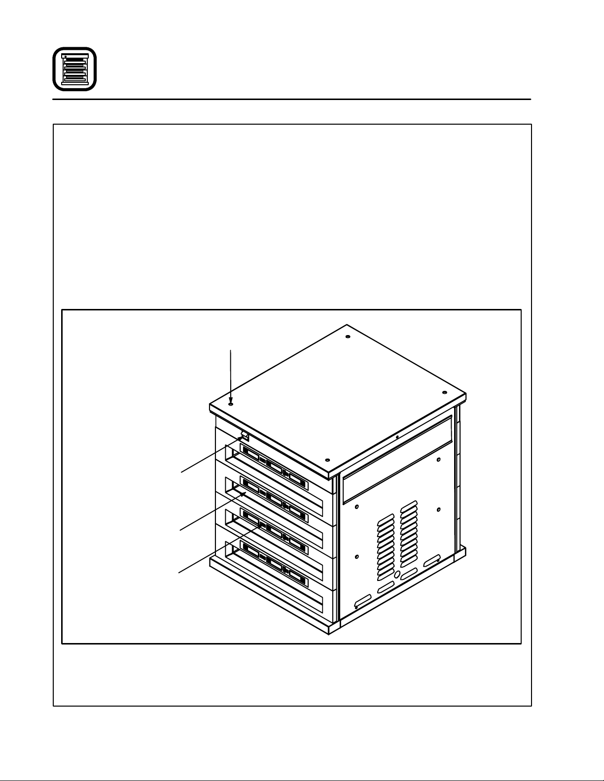
Description
The Blodgett Universal Holding Cabinet is a short
term holding device designed to maintain the
freshness of a variety of food product. The UHC
contains four product slots which can be controlled independently. Control panels are located
above each slot on both the front and rear of the
cabinet. All operator mode selections can be
made from either the front or rear display.
Power Switch --- controls power to the cabinet.
Product Slot --- holds up tothreetrays ofproduct
per slot.
Control Panel --- indicates the holding time and
product selection for each tray position.
Knockouts for
Double Stacking
1/3 Size Product Tray - -- designed for all grilled
products (meat, eggs, chicken). This tray maintains the product’s moisture.
1/2 Size Crumb Tray with Wire Rack --- designed
for fried products (crispy chicken, nuggets, fillet).
The tray keeps the fried crumbs from dropping
through the racks. It also allows moisture to escape leaving the outside of the product crispy.
Full Size Product T ray --- designed for bread
products (biscuits and muffins). This tray allowsa
small amount of moisture to escape.
Power Switch
Product Slot
Control Panel
Figure 1
2
Page 7

Installation
Delivery and Location
DELIVERY AND INSPECTION
All Blodgett holding cabinets are shipped in containers to prevent damage. Upon delivery of your
new unit:
D
Inspectthe shippingcontainerforexternaldamage. Any evidenceof damage should be noted
onthedelivery receiptwhichmustbe signed by
the driver.
D
Uncratetheunit and checkforinternaldamage.
Carriers will accept claims for concealed damage if notified within fifteen days of delivery and
the shipping container is retained for inspection.
The Blodgett Oven Company cannot assume
responsibility for loss or dama ge suffered in
transit. The carrier assumed full responsibility
for delivery in good order when the shipment
was accepted. We are, however, prepared to
assist you if filing a claim is necessary.
Each Universal Holding Cabinet is shipped with
the following:
D
Equipment manual
D
PM card
D
Training video
D
Quick-reference guide
D
Cleaning brush
At this time, please complete and return the
Service Tracking card shipped with your oven.
LOCATION
Thefollowing clearancesmustbeavailableforservicing.
D
Cabinet body sides --- 22” (56 cm)
D
Cabinet body back --- 25” (64 cm)
3
Page 8
Installation
Assembly and Connection
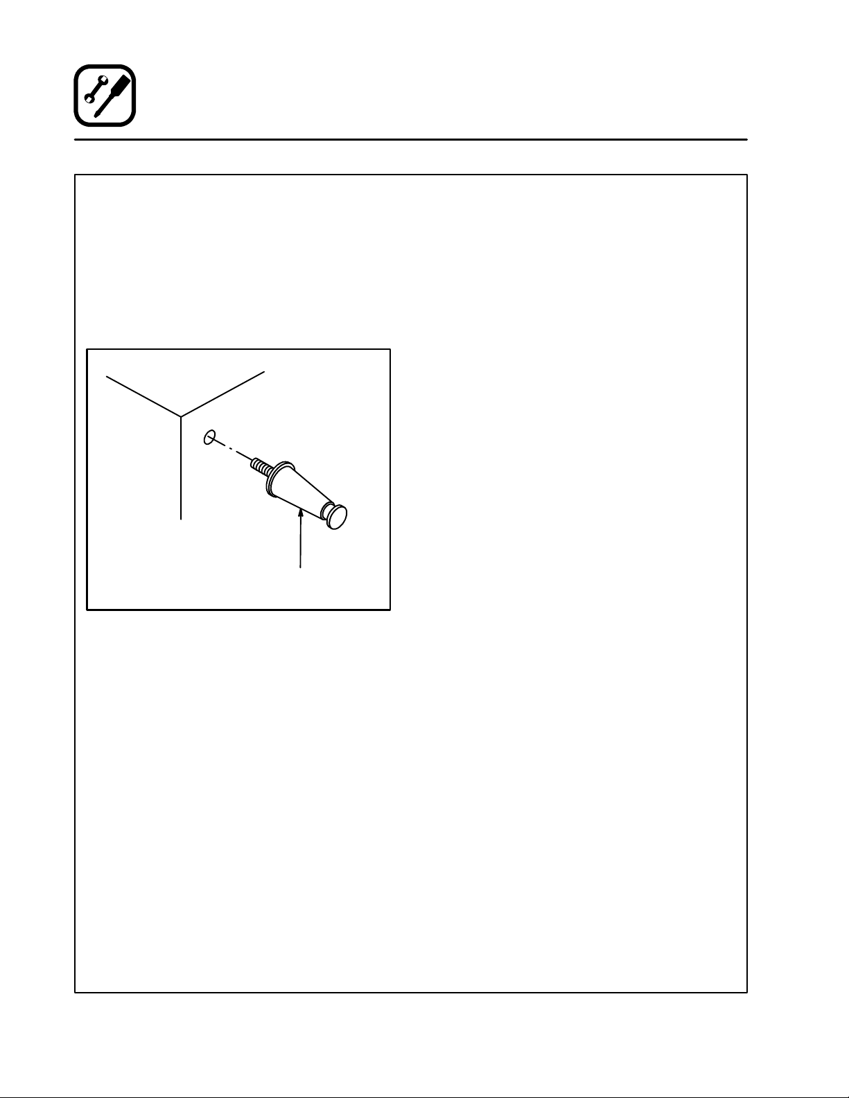
LEG ATTACHMENT
1. Lay the unit on its side.
2. Screw one 4” (10 cm) leg into each of the four
holes located near the corners on the bottom
of the UHC. See Figure 2.
3. Use a tool to tighten the hex nut at the top of
each leg.
4. Lift the unit onto the legs.
Bottom of
Cabinet
4” (10 cm)
Leg
ASSEMBLY TO STAND
1. Place the unit on top of the cart.
NOTE: Be surethelocking casters are facing
the front of the cabinet, the side with
the power switch.
2. Bolt the corners of the unit to the stand from
the underside of the stand top using 3/8” x
5/8” bolts provided.
Figure 2
4
Page 9
Installation
Assembly and Connection
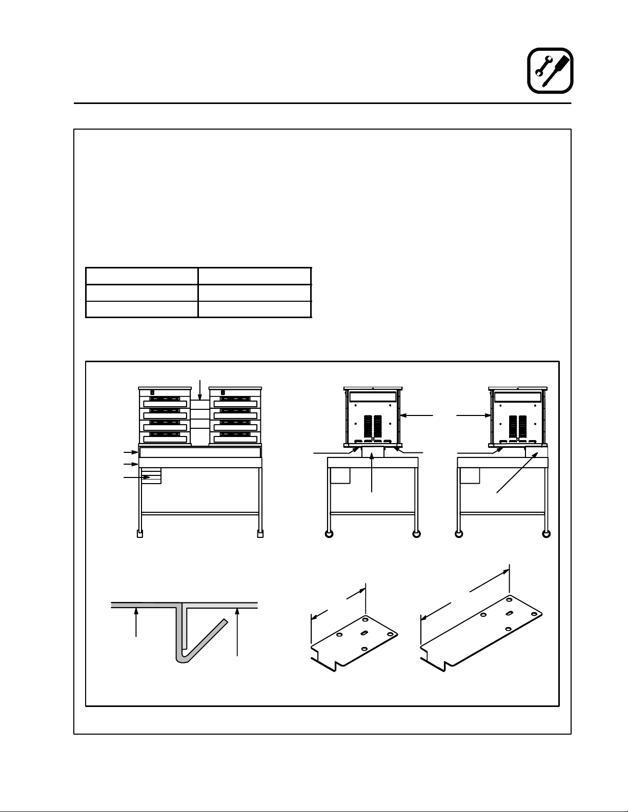
ASSEMBLY TO DUAL UHC TABLE WITH RISER
TheUHCcanbemountedonthetableforeither
double or single sided access. See Figure 3. For
double sided access the unit is centered on the
table. Forsinglesided access the unit is mounted
flush to the back of the table.
Besurethat youhavethecorrect mountingbrackets for your configuration. Refer to t he following
table.
Mounting Style
Bracket Length
Double Sided Access Short (6”, 15.5 cm)
Single Sided Access Long (12”, 31 cm)
NOTE: The installation requires two brackets per
UHC.
Tool Accessory
Bench
Table
Shelves
Hold Down
Bracket
(See View A)
1. Place the unit on top of the riser of the dual
UHC table.
2. Line up the center hole on each hold down
bracket with a leg mounting hole on the bottomoftheunit.Bolttwobracketstothebottom
of each UHC using the 3/8” x 5/8” bolts provided.Besure the formedangleofthebracket
cups the underside edge of the bench. See
Figure 3.
For Double Sided Access
Installonebracket ontheouterfrontcornerof
eachUHC.Installtheother bracketon theouter back corner of each UHC.
For Single Sided Access
Installonebracket ontheouterfrontcornerof
each UHC. Install the other bracket on the inner front corner of each UHC.
UHC
Hold Down
Bracket
Hold Down
Bracket
RiserSupport
Front View Side View
UHC
Riser
View A
Side View
(Double Sided Access)
6” (15.5 cm)
Double Sided Access
Short Bracket
Figure 3
5
RiserSupport
Side View
(SingleSided Access)
12” (31 cm)
Single Sided Access
Long Bracket
Page 10
Installation
Assembly and Connection
DOUBLE STACKING
1. Remove the four knockoutsfromthetop of the
lower unit.
2. Place the upper unit in position on top of the
lower unit.
3. Remove the side panels from the lower unit.
4. Attach the lower unit to the upper unit using
four 3/8” x 5/8” long bolts provided.
NOTE: The holes in the bottom of the upper
unit are the same as the leg mounting
holes. Theholesinthetop of thelower
unit are knockouts.
5. Replace the side panels.
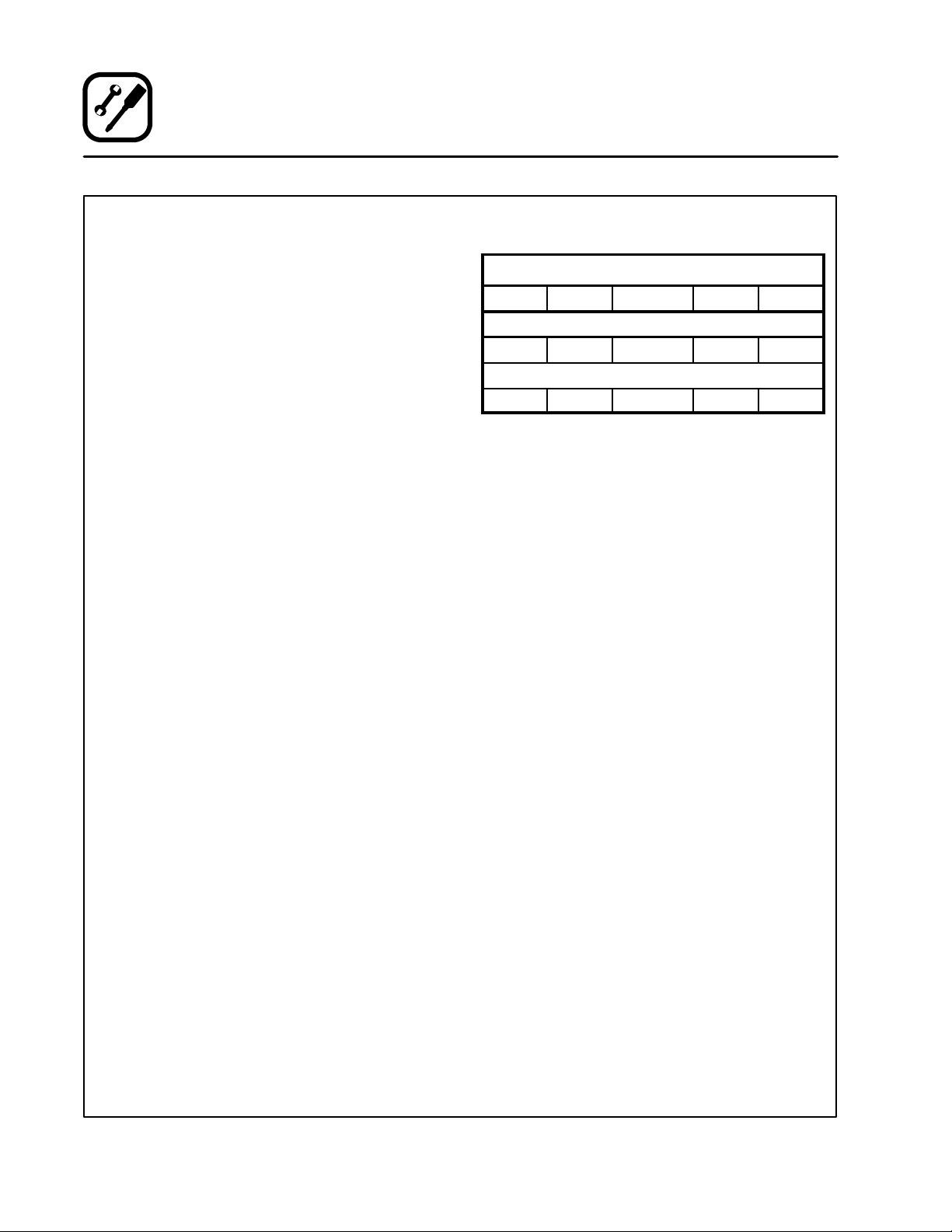
ELECTRICAL CONNECTION AND POWER UP
Electrical Specifications (per section)
KW Hz Volts Phase Amps
U.S. and Canadian installations
3.6 60 208/240 1 20
General Export installations
3.6 50/60 208-240 1 20
Installation must conform with local codes, or in
theabsenceoflocalcodes,withthe NationalElec-
trical Code, ANSI/NFPA 70---Latest Edition and/or
Canadian Electrical Code CSA C22.2 as applica-
ble.
Wiring diagrams are located inside the right side
panel.
This appliance is equipped with a three-prong
grounding plug for your protection against shock
hazard and must be plugged into a properly
groundedthree-prongreceptacle. DONOT cutor
remove the grounding prong from this plug.
1. Plug the UHC into the power source.
2. Togglethepowerswitchto ON.Allof the control displays illuminate.
3. Monitorthe temperatureof the slots. It should
take approximately15 minutes for the slots to
heat from room temperature to a 155_F
(68_C) setpoint. It should take approximately
25minutes forthe slotsto heatfromroomtemperature to a 200_F(93_C) setpoint.
THE BLODGETT OVEN COMPANY CANNOT ASSUMERESPONSIBILITYFORLOSSOR DAMAGE
SUFFEREDASA RESULTOFIMPROPERINSTALLATION.
6
Page 11

THE INFORMA TION CONTAINED IN THIS SECTIONIS PROVIDEDFORTHEUSEOFQUALIFIED
OPERATING PERSONNEL. QUALIFIEDOPERATING PERSONNEL ARE THOSE WHO HAVE
CAREFULLY READ THE INFORMATION CONTAINED IN THIS MANUAL, ARE FAMILIAR WITH
THE FUNCTIONS OF THE UNIT AND/OR HAVE
HAD PREVIOUS EXPERIENCE WITH THE OPERATIONOFTHE EQUIPMENTDESCRIBED.ADHERENCE TO THE PROCEDURES RECOMMENDED HEREIN WILL ASSURE THE
ACHIEVEMENT OF OPTIMUM PERFORMANCE
AND LONG, TROUBLE-FREE SERVICE.
Please take the time to read the following safety
andoperatinginstructions.Theyare the keytothe
successful operation of your Blodgett UHC.
Operation
Safety Information
SAFETY TIPS
For your safety read before operating
General safety tips:
D
DO NOT remove the control panels unless the
unit is unplugged.
D
DO NOT operate the UHC unless it has been
properly installed and checked.
D
DONOToperatetheU HC unlessallserviceand
access panels are in place and properly secured.
D
Use caution when operating the UHC to avoid
contact with heated surfaces.
7
Page 12
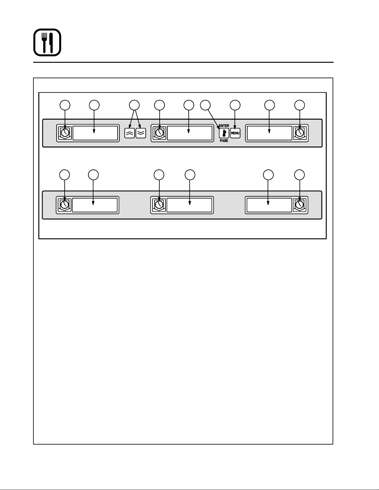
Operation
Control Panel Descriptions
1 1 12 2 25 4 3
1 1 12 2 2
UHC Front Control Panel
UHC Rear Control Panel
FRONT CONTROL PANEL
1. TIMER KEYS --- start and stopthe timer associated with each tray position. The timer keys
also turn off audible alarms. There are three
timerkeys oneachfrontpanel(left,centerand
right).
2. DISPLAYS --- show productselectionandhold
time for each tray position. The displays also
provide programming information in the program mode.Therearethreedisplaysoneach
front panel (left, center and right).
3. MENU KEY --- press to select meal transitions
(breakfast to lunch), clean mode operation
andtoturn individualslots onoroff. Themenu
key also provides access to the program
mode.
4. TEMPERATURE/ENTER/PAGE KEY --- this
key has three separate functions.
D
Display slot temperature information
D
Enter operationalchanges
D
Select page parameters in program mode.
5. UP and DOWN ARROW KEYS --- press to increase/decrease variables or change selections.
Figure 4
REAR CONTROL PANEL
NOTE: The rear panels are used for operational
functions only. All programming must be
performed from the front panels.
1. TIMER KEYS --- start and stopthe timer associated with each tray position. The timer keys
also turn off audible alarms. There are three
timerkeys oneachfrontpanel(left,centerand
right).
2. DISPLAYS --- show productselectionandhold
timeforeachtray position.Therearethreedisplays on each front panel (left, center and
right).
8
Page 13

Operation
Operator Mode
The operator mode is the normal operating mode
of the controller when all slots are at the proper
temperature and no alarm conditions exist. Product information and hold time are displayed.
SLOT TEMPERATURE CONTROL
Each product selection has its own temperature
setpoint and product hold time. All product timers
run independently.
Theslott emperature is controlledby the temperature setpoint ofthe leftmost productentry ineach
slot as viewed from the front of the cabinet (side
with the On/Off switch). Product selections that
have a hold temperature different than the left
most product selection will not be available for
entry into that slot’s configuration.
DISPLAY INFORMATION
In the operator mode the slot displaysprovidethe
following information:
D
The product selection for each tray location.
D
The hold time remaining (in minutes) for active
timers.
NOTE: An active timer alternately displays the
product selection and the time remaining.
Inactive timers displayonlyproduct selection.
DISPLAY IDENTIFICATION
Since there are three separate displays for each
slot it is important to identify product status for
each display. The operator mode indicates hold
time status by changing the display intensity.
There are three levels of display intensity used to
indicate product status.
D
USE FIRST DISPLAY --- indicates the product
with the least amount of hold time remaining.
This displayisidentified bythe brightestlevelof
intensity and running dots along the bottom of
the display.
D
ACTIVE TIMER --- indicates an active timer that
is not the product with the least amount of hold
time remaining. This display is identified by a
medium level of intensity.
D
INACTIVE TIMER --- only product selection is
displayed for inactive timers. This display is
identified by the lowest level of intensity.
SAUS
!.!.!
.
Use first timer
(highest intensity)
12
.!.!.!.
.
Running dots(decimal points)
Active timer
(medium intensity)
Figure 5
9
Inactive timer
(lowest intensity)
Page 14

Operation
Timer Operation
Starting a timer
1. Press the TIMER KEY above the desired t ray
position to start t he timer. The timer counts
down from a preset value and alternatelydisplays product selection and the hold time re maining.
2. Wait a minimumof3seconds beforepressing
another timer key t o initiate a secondary timing function.
NOTE: If more than one tray of product is timing,
the tray with the least hold time remaining
is indicated by the Use First display.
Adjusting a timer
1. Press the TIMER KEY to initiate the product
timer (if not already activated).
2. Press the TIMER KEY again within 3 seconds
to decrease the hold time by 5 minutes.
NOTE: The hold time will be decreased by 5
minutes each time the product key is
pressed.
3. The timer becomes active 3 seconds afterthe
lastkeypress.Thedisplayindicates themaximum holding time for the product and
changestoDisplayIntensity3 (brightest).The
display alternately displays the remaining
hold time and product mnemonic.
Stopping a timer
1. Press the TIMER KEY above the slot position to
turn off an active timer. The timer stops timing.
The display changes to the inactive status.
Timing out
1. Thetimeoutalarm alerts the operator that the
productholdtimehasexpired.Whenthehold
timeremainingreacheszeroan audiblealarm
sounds and the display reads --- 00 --- .
All other active displays in the cabinet switch
to the lowest intensity level until the audible
alarm is turned off.
2. Press the TIMER KEY to clear the timed out
display and silence the alarm.
If other timers in the cabinet have timed out,
theaudiblealarmremainsonuntilalltimedout
displays are cleared.
3. When all timers are cleared, active timers return to normal status. The Use First status is
switched to the next timer with the least hold
time remaining.
10
Page 15

SAUS
.!.!.!.
45
!.!.!
.
SAUS
.!.!.!.
.
Display alternately indicates hold time and
product selection for active timers.
Operation
Timer Operation
Press timer key to start a timer
--- 00 ---
Press timer key to stop or silencea timer
!.!.!
.
Use First indication changes to the next active timer
SAUS
.!.!.!.
Figure 6
.
11
Page 16

Operation
Meal Selection
Selecting breakfast and lunch
NOTE: The following example is for selecting
breakfast.Thesameprocedureappliesfor
selecting lunch.
1. Press the MENU KEY to change the product
selectionofthe slotfrombreakfastto lunch.All
displays are highlighted.
2. Press the ENTER KEY to activate the meal
selection. The displays switch to the inactive
mode.
NOTE: If the enter key is not pressed within
fiveseconds,theproductselectionreturns to the breakfast meal selection.
Changing meal selections
Active timers will not change to the new meal
selection until the timer(s) are stopped or time out
and are reset. Activetimersarestoppedbypressing the timer key.
If the product selection for the meal has a hold
temperaturedifferentthanthe currentmeal,a high
or low temperature alarm is displayed to alert the
operator that the hold temperature is being
changed.Shouldthehigh orlowtemperaturecondition remain for two or more minutes, an audible
alarmsounds.Tosilencethealarmpressanytimer
key.Thisdoesnotaffectthetimeroperationunless
the timer key is pressed again. The display alternately indicates the product selection and the
alarm message until the slot temperature is within
the preset limits.
If no keys are pressed, the alarm message automaticallyresets wh en the slot temperature is within the preset limits.
NUGG
Press menu key to display inactive
meal selection
NUGG NUGG
Press enter key to enter meal selection
and return to normal displaymode
Figure 7
12
Page 17

Operation
Clean Mode
The clean mode changes the temperature setpoint of all slots in the cabinet to 125_F(52_C).
To start the clean mode
1. PresstheMENUKEYtoscrolltotheclean
mode message, CLN MODE.
2. Press the ENTER KEY to activate the clean
mode. All slots change to clean mode.
NOTE: If the enterkeyis not pressed within 5
seconds thecontrolreturnstotheprevious meal selection.
If the t emperature is above 125_F(52_C),the
display alternately reads SLOT CLN MODE
CLN MODE
and NOT SAFE YET. The display reads SAFE
TO CLN when the slot is 125_F(52_C).
To ex it clean mode
1. Press the MENU KEY to display CLN MODE.
2. Press the ENTER KEY to exit the clean mode
and return to normal operation. The slot alternately displays SLOT TEMP LOW and the
productselectionuntilthetemperature iswithin the normal operating limits.
NOTE: If the enter key is not pressed within 5
seconds the slot returns to the clean
mode.
Press menu key to scroll to clean
mode message
Press enter key to start clean mode
SAFE TO CLN
CLN MODE
To exit clean mode press menu key
to display clean mode message
EXIT CLN MODE
Press enter key to return to normal
displaymode
Figure 8
13
Page 18

Operation
Slot On/Off
To turn slot off
1. Press the MENU KEY to scroll to the slot off
message, TURN SLOT OFF.
2. Press t he ENTER KEY to enter the selection.
The display reads SLOT IS OFF.
NOTE: If the enter key is not pressed within
five seconds the product selection returns to the operator mode.
TURN SLOT OFF
To turn slot on
1. Press the MENU KEY to scroll to the slot on
message, TURN SLOT ON.
2. Press the ENTER KEY to enter the selection
and return to the operator mode. The display
alternately reads SLOT TEMP LOW and the
productselectionuntilthetemperature iswithin normal operating limits..
NOTE: If the enter key is not pressed within
fiveseconds the slot returnstoslotoff
status.
Press menu key to scroll to slot off
message
Press enter key to turn slot off
SLOT IS OFF
SLOT IS OFF
Press menu key to scroll to slot on
message
TURN SLOT ON
Press enterkey to turn sloton and return
to normal display mode
Figure 9
14
Page 19

Operation
Displaying Slot Temperature Information
1. Press t he TEMPERATURE KEY to scroll the
following temperature information for each
slot:
D
Top plate actual temperature
D
Bottom plate actual temperature
D
Top plate setpoint temperature
D
Bottom plate setpoint temperature
TOP TEMP 155
BOT TEMP 155
2. Pressthe TEMPERATUREKEYagaintoreturn
the display to operator mode.
NOTE: The display automatically returns to
operator mode if no keyispressed for
five seconds.
Press temperature key to display top
platetemperature
Press temperature key to display
bottom plate temperature
Press temperature key to display top
platesetpoint temperature
TOP TSET 155
Presstemperaturekey to display bottom
platesetpoint temperature
BOT TSET 155
Press temperature key to turn return to
normal display mode
Figure 10
15
Page 20

Operation
Temperature Alarms
There are five temperature alarm functions.
D
High temperature alarm
D
Low temperature alarm
D
FDA alarm
D
Sensor alarm
D
Rise time alarm
Ifalarmconditionsoccuranaudible alarmsounds
and the displays alternately give the product
selection and an alarm message. Timers cannot
be started when a slot is in alarm condition.
Hi and Low Temperature alarm
Ifthe slottemperatureisaboveorbelowthe preset
limitsfor a product selection, the controllerenters
the high orlow alarm condition. The display reads
either SLOT TEMP HIGH or SLOT TEMP LOW.
Should the high or low temperature condition remain for two or more minutes, an audible alarm
sounds. To silence the alarm press any timer key.
HIGH/LOW TEMPERATURE ALARM
1. The displays alternately display the product
selection and the alarm messageuntil the slot
temperature is within the preset limits.
NOTE: The low temperature audible alarm is in-
hibited at powerup.TheSLOTTEMP LOW
messageisdisplayed until theslotiswithin the preset limits.
Food and Drug Administration (FDA) alarm
The FDA alarm indicates the slot temperature is
belowthe preset limit toholdthe product. The audible alarm sounds and the display reads TEMP
UNDR FDA. Active timers are automaticallyreset.
1. Toturn off the audible alarm press any TIMER
KEY. The alarmmessageremains untiltheslot
temperature is within the preset limits. If no
keysarepressedtheaudiblealarmand alarm
message remain.
A timer key must be pressed to clear an FDA
alarm.
FDA ALARM
SLOT TEMP LOW
Press any timer key to silence audible alarm
SLOT TEMP HIGH
Press any timer key to silence audible alarm
TEMP UNDR FDA
Press any timer key to silence audible alarm
Figure 11
16
Page 21

Operation
Temperature Alarms
Sensor Range alarm
The sensor fail alarm indicates a sensor temperature value above or below the operating limits of
the slot, 50---250_F (10-121_C).
1. Toturn off the audible alarm press any TIMER
KEY. The alarm message isdisplayeduntil the
slot temperature is within the operating limits.
Power to the slot’s heaters is turned off until
the sensor is repaired.
Service is required to correct a sensor alarm.
SENSOR RANGE ALARM
SENS ALRM
Press any timer key to silence audible alarm
RISE TIME ALARM
Rise Time alarm
Therisetimealarmindicates thattheslottemperature failed to reach operating temperature within
the preset time limits of the system at power up.
1. Toturn off the audible alarm press any TIMER
KEY.
Service is required to correct a rise time alarm.
SLOT RISE RATE
Press any timer key to silence audible alarm
Figure 12
17
Page 22

Operation
Product Selection for Each Slot
Program mode is used to select the products for
each slot. All entries are made through PAGE and
MENUselections.Eachslothas apageofconfiguration menus. The topslot in the cabinet is Slot 1.
D
The PAGE key selects the slot (1-4) pages.
D
The MENU key selects the configuration menu
items (meal and tray location).
D
The UP/DOWN arrow keys select the available
products for each meal.
PROG MODE
To enter Program Mode
1. Pressand holdthe MENU KEY forat least five
seconds. The display reads PROG MODE.
To enter Page Selections
Eachslotpage(1-4)containsproductselectionfor
each meal.
1. PressthePAGEKEYtoscrolltotheslot(1-4)
pages.
Press and holdmenu key to enter
program mode
Press page key to scroll slot page
selections
SLOT 1
SLOT 2
SLOT 3
SLOT 4
Figure 13
Press page key to scroll slot page
selections
Press page key to scroll slot page
selections
Press page key to scroll slot page
selections
18
Page 23

Meal Selection and Tray Position
1. Press the MENU KEY to scroll the meal and
tray position in the left and center displays.
SLOT 1 PAGE
BFST LEFT SAUS
Operation
Product Selection for Each Slot
The current product selection is indicated in
the right display.
Press menu to key to scroll
meal selection and tray position
Meal Selection Tray Position
Press menu to key to scroll
meal selection and tray position
BFST CENT SAUS
Meal Selection Tray Position
Press menu to key to scroll
meal selection and tray position
BFST RGHT SAUS
Meal Selection Tray Position
Press menu to key to scroll
meal selection and tray position
LNCH LEFT 10-1
Meal Selection Tray Position
Press menu to key to scroll
meal selection and tray position
LNCH CENT 10-1
Meal Selection Tray Position
Press menu to key to scroll
meal selection and tray position
LNCH RGHT 10-1
Meal Selection Tray Position
Figure 14
19
Press menu to key to scroll
meal selection and tray position
Page 24

Operation
Product Selection for Each Slot
To enter Product Selection
1. Press the UP/DOWN ARROW KEYS to scroll
the availableproduct selectionsfor each meal
and tray position.
The product selection for the left tray position of
each meal determines the hold temperature for
the slot. Only products that have hold temperatures within 5_F(2.8_C) of the left most product
selection willbe displayedfor selection inthe center and right tray position. If the left most product
selection is changed, the center and right posi-
PRODUCT SELECTION
BFST LEFT SAUS
Pressup/down arrow keysto
scroll product selections
BFST LEFT ROUN
Pressup/down arrow keysto
scroll product selections
tions must be reentered. If the product selection
for an active timer is changed, the timer is automatically reset.
To exit Program Mode
1. Press and hold the MENU KEY for five seconds.
NOTE: The controller automatically exits the
program mode if no entries are made
for five minutes.
Product Selections
BFST LEFT FOLD
BFST LEFT SCRA
EXITING PROGRAM MODE
BFST LEFT SCRA
Pressup/down arrow keysto
scroll product selections
Figure 15
20
Product Selections
Product Selections
Press and hold the menu key for
five seconds to exitprogram mode
Page 25

Sample product selection change
Thisexamplechangesthelunchproductselection
in the left position of slot 3 from 10-1 to NUGG.
Since the hold temperature for NUGG is different
than 10-1, the center and right product selections
PROG MODE
Operation
Product Selection for Each Slot
are cleared. Only items with hold temperatures
within5_F(2.8_C)ofthe left product selectioncan
be entered for the center and right position.
Press menu to key for five seconds
to enter the program mode
Press page key to scroll slot page
selections
SLOT 1
Press page key to scroll slot page
selections
SLOT 2
Press page key to scroll slot page
selections
SLOT 3
Press menu key to scroll meal
selection and tray position
BFST LEFT SAUS
Meal Selection Tray Position
Press menu key to scroll meal
selection and tray position
21
Page 26

Operation
Product Selection for Each Slot
BFST CENT SAUS
Meal Selection Tray Position
Press menu key to scroll meal
selection and tray position
BFST RGHT SAUS
Meal Selection Tray Position
Press menu key to scroll meal
selection and tray position
LNCH LEFT 10-1
Meal Selection Tray Position
Press menu key to scroll meal
selection and tray position
LNCH LEFT 4-1
Pressup/down arrow keysto scrollproduct selections
LNCH LEFT NUGG
Figure 16
22
Press and holdmenu key for five
seconds to exit program mode
Page 27

Operation
Entering and Editing Product Information
Changing or entering new product selections,
hold timer and temperature setting are password
protected functions.
To enter the password
1. Press and hold the MENU KEY for five seconds. The display reads PROG MODE.
2. Press the PAGE KEY to scroll to VIEW PAGE.
3. Press the MENU KEY to select the security
lock, SECRLOCK.UsetheUPandDOWNARROW KEYS to enter the security code 1 2 3.
ENTERING THE PASSWORD
PROG MODE
A new product entry requires entry of:
D
the product name,
D
hold time,
D
hold temperature from 55-250_F (13-121_C),
D
meal selection
The following example enters a new product,
named XXY, with a hold time of 25 minutes, and
hold temperature of 180_F(82_C).
Press and holdmenu key to enter
program mode
Press page key to scroll view page
VIEW PAGE
Press menu key to scroll to the
security lock
SECR LOCK 156
Press up/down arrow keys to enter password
SECR LOCK 123
Figure 17
23
Page 28

Operation
Entering and Editing Product Information
ENTERING THE PRODUCT NAME
SECR LOCK 123
EDIT PAGE SAUS
PROD NAME .
Press page key to scroll to the edit page
Press menu key to scroll to an
unused product(blank) mnenonic
Press up arrowkey to
scroll to the letter X
NOTE: The decimal point indicates which
display segment is beingentered.
PROD NAME X.
Press down arrow key to scroll to the next display segment
PROD NAME X.
Press up arrow key to scroll to the letter X
PROD NAME XX.
Press down arrow key to scroll to the next display segment
PROD NAME XX.
Press up arrow key to scroll to the letter Y
PROD NAME XXY.
Figure 18
24
Page 29

ENTERING THE PRODUCT HOLD TIME
PROD NAME XXY.
TIME PAGE XXY
XXY TIME 20
Operation
Entering and Editing Product Information
Press page key to scroll to the edit page
Press menu key to scroll to product
time selection
Press up/down arrow key to change time to 25 minutes
XXY TIME 25
Figure 19
25
Page 30

Operation
Entering and Editing Product Information
ENTERING THE PRODUCT HOLD TEMPERATURE
XXY TIME 25
TEMP PAGE XXY
XXY Ttop 155
Press up/down arrow key to change top plate temperature
Press page key to scroll to the temp page
Press menu key to scroll to product
top plate temperature selection
XXY Ttop 180
Press menu key to scroll to product
bottom plate temperature selection
XXY Tbot 155
Press up/down arrow key to change bottom plate temperature
XXY Tbot 180
Figure 20
26
Page 31

ENTERING MEAL USAGE
XXY Tbot 180
MEAL PAGE XXY
XXY MEAL ALL
Operation
Entering and Editing Product Information
Press page key to scroll to the meal page
Press menu key to scroll to product
meal selection
Press up/down arrow keys to select BFST
XXY MEAL BFST
Figure 21
27
Page 32

Operation
More Product Prompt Time Feature
A cook more time may be entered for each product type that will alert the operator to cook more
product before the holding time reaches zero.
When the product timer equals the cook time the
audible alarm will chirp for 3 seconds and the display message will alternately display PRODUCT
NAME,TIMERTIME,COOKand MORE until the
timer times out. If more than one tray of a product
type is active the cook more alarm will not occur
until allactive timers reach the cook time.If a position is indicating, COOK MORE and another timer
of the same product is started, the COOK MORE
message will be cleared. During transition from
breakfast to lunch the COOK MORE indication is
disabled. Use the following procedure to change
or enter the cook time of a product svelection:
DEFAULT SELECTIONS FOR THE PROMPT TIME
MNEMONICS
Left Center Right*
COOK PAGE Cook Page
SAUS COOK 4 Product 1 Cook Time 0 --- 30 Minutes 3
ROUN COOK 4 Product 2 Cook Time 0 --- 30 Minutes 3
1. Press and hold the menu key for 5 seconds.
2. Pressthepagekeytoscrolltoviewpage.
3. Press the menu key to scroll to the security
lock.
4. Pressthe upanddown arrowkeysto enterthe
manager security code: 3 3 1.
5. Press the page key to scroll to cook page.
6. Pressthemenu key to scrollto productselection.
7. Pressthe up anddownarrowkeys toincrease
ordecreasetheprompttime(inminutes)to
cook more product.
8. Whencomplete,pressandholdthemenukey
for 5 seconds to return to normal operation.
Description Available
Settings Level
Access
FOLD COOK 3 Product 3 Cook Time 0 --- 30 Minutes 3
SCRA COOK 3 Product 4 Cook Time 0 --- 30 Minut es 3
RBAC COOK 0 Product 5 Cook Time 0--- 30 Minutes 3
CBAC COOK 1 Product 6 Cook Time 0 --- 30 Minutes 3
MUFF COOK 3 Product 7 Cook Time 0 --- 30 Minutes 3
BISC COOK 22 Product 8 Cook Time 0 --- 30 Minutes 3
BURR COOK 0 Product 9 Cook Time 0 --- 30 Minutes 3
10 --- 1 COOK 2 Product 10 Cook Time 0 --- 30 Minutes 3
4 --- 1 COOK 4 Product 11 Cook Time 0 --- 30 Minutes 3
GRCK COOK 5 Product 12 Cook Time 0 --- 30 Minutes 3
NUGG COOK 5 Product 13 Cook Time 0 --- 30 Minutes 3
FISH COOK 5 Product 14 Cook Time 0 --- 30 Minutes 3
McCK COOK 7 Product 15 Cook Time 0 --- 30 Minutes 3
NOTE: Therightdisplaygivesthetimein minutes.
28
Page 33

Operation
Display Adjustments
Changing the Display Time
The rate at which an active timer alternately displays product selection and hold time may be adjusted as follows:
1. Press and hold the MENU KEY for five seconds.
2. Press the PAGE KEY to scroll to VIEW PAGE.
3. PresstheMENUKEYtoscrolltothesecurity
lock, SCR LOCK.
4. Pressthe UPandDOWNARROW KEYStoenter the security code 1 2 3.
5. PresstheMENUKEYtoscrolltoproductdisplay time, PROD TIME.
6. Press the UP and DOWN ARROW KEYS to
change the product display time.
7. PresstheMENUKEYtoscrolltotimerdisplay
time, TIMR TIME.
8. Press the UP and DOWN ARROW KEYS to
change the timer display time.
9. Press and hold the MENU KEY for five seconds to return to normal operation.
Changing from _Fto_C
The followingchanges the temperature units from
_Fto_C.
NOTE: Your UHC is factory programmed with the
proper temperature units. Access to level 3
programming is required to change the
units. Should you need to change the units
contact your local service agent for assistance.
1. Press and hold the MENU KEY for five seconds.
2. Press the PAGE KEY to scroll to VIEW PAGE.
3. PresstheMENUKEYtoscrolltothesecurity
lock, SCR LOCK.
4. Pressthe UPandDOWNARROW KEYStoenter the security code.
5. PresstheMENUKEYto scrolltodisplayunits.
6. Press the UP and DOWN ARROW KEYS to
change from _Fto_C.
7. Press and hold the MENU KEY for five seconds to return to normal operation.
Changing the Display Intensity
The brightnessofeachof the three intensitylevels
used for product status may be adjusted as follows:
1. Press and hold the MENU KEY for five seconds.
2. Press the PAGE KEY to scroll to VIEW PAGE.
3. PresstheMENUKEYtoscrolltothesecurity
lock, SCR LOCK.
4. Pressthe UPandDOWNARROW KEYStoenter the security code 1 2 3.
5. PresstheMENUKEYtoscrolltodisplayintensity level. The display reads DISP IntX.There
are three display intensity levels.
Level #
1 (dimmest) Int1 10---25 10
2 (mid-level) Int2 10---25 10
3(brightest) Int3 67-100 100
6. Press the UP and DOWN ARROW KEYS to
change the intensity level.
7. Press and hold the MENU KEY for five seconds to return to normal operation.
Display Range Default
29
Page 34

Operation
Operating Tips and Menus
Correct heat and moisture levels are important to
the proper operation of the UHC. There are no
doors inthe cabinet.Thetrays act as doors,therefore it is important that they be positioned correctly. The trays must be inserted to the stop line. The
stop line is clearly marked on the handle of all
three tray styles.
Product Slots
The UHC has four slots that can hold up to three
trays of product per s lot.
Slot 1
Slot 2
Slot 3
Slot 4
Baked Products
Thefullsizetrayisdesignedtoholdallbaked
products such as biscuits and muffins.
D
UseaUHCtraylinerwiththefullsizetray.
D
After biscuits have been removed from the biscuit oven, remove the wrapper and open the
cardboard box. Slide the biscuits onto the tray
liner.
D
Fullsize trayscan hold up to 30 frozen biscuits,
20 scratch biscuits or 20 muffins.
Grilled Products
The 1/3 tray is designed to hold all grilled products.
D
Product shouldnot be drained when picked up
from the grill.
D
Use a UHC tray liner with the 1/3 tray.
D
Product should be stacked when placed in the
lined1/3 sizetray.10:1and sausagepattiescan
be stacked up to six high. Eggs (except
scrambled), grilled chicken and 4:1 patties can
bestackeduptothreehigh.
D
Productshould be placedtowardsthecenterof
the tray.
Figure 22
Fried Products
The 1/2 crumb tray with the wire rack is designed
to hold all fried products.
D
Product should be held in the wire rack which
is placed in the crumb tray.
D
UHC tray liners are not necessary when using
thewirerackforfriedproduct.
Figure 23
30
Page 35

Operation
Operating Tips and Menus
Thefollowing arecopiesof the ProductionControl
Charts for the breakfast and regular menus. The
laminated charts can be ordered through O’Brien
Budd, Inc. The ordering numbers are:
D
Breakfast UHC card #MCD 63102
D
Regular Menu UHC card #MDC 63102A
WEEKEND(S) REGULAR MENU
Recommended Tray Size/
Recommended Stack
Ultra High Volume 18 / 6 15 / 3 15 / 3 1/1 10 / 1 14 / 1
Units Trays Trays #Pieces Bags #Pieces #Pieces
Time Period 10:1 4:1 GRCK NUGG McCK FISH
WEEKEND(S) BREAKFAST MENU
9/3 9/3 8/3 1/1 8/1 8/1
Ultra high volume should be used when the grills
and fryers are set up in such as way that they can
cook all the items that can fit in one tray at the
same time. For example, a restaurant cooks two
runs of 9 patties of 10:1 at the same time. In this
case the 18 pattiescan be staged in one tray and
stackeduptosixhigh.
These charts indicate how may pieces of each individual menu items fit in the trays.
Recommended Tray Size/
Recommended Stack
Ultra High Volume 30 / 1 24 / 6 18 / 3 6/1 18 / 3 30 / 3 20 / 1 9/1
Units Trays Trays Trays Trays Trays Trays Trays Trays
Time Period BISC SAUS FOLD SCRA ROUN CBAC MUFF BURR
30 / 1 12 / 3 6/3 6/1 6/3 15 / 3 5/1 9/1
31
Page 36

Operation
Operating Tips and Menus
LUNCH (REGULAR) MENU
Stack
Product
10:1 6 18 Trays Yes 1/3 size
4:1 3 15 Trays Yes 1/3 size
Grilled
Chicken
Deluxe
Nuggets 1 1Bag Bags No 1/2 size wire 20
Crispy
Chicken
Deluxe
Fish Fillet
Deluxe
(maximum)
3 15 #Pieces Yes
1 10 #Pieces No 1/2 size wire 20
1 12 #Pieces No 1/2 size wire 30
Tray
Amount
(maximum)
Units Liner Tray Type
plastic
plastic
1/3 size
plastic
Maximum
Hold
25
25
30
NOTE: All products reflect maximum holding time in the UHC. All products can be heldfor an additional
10 minutes in the transfer bin.
32
Page 37

BREAKFAST MENU
Operation
Operating Tips and Menus
Stack
Product
Biscuits 1 30 Trays Yes Full size
Sausage 6 24 Trays Yes 1/3 size
Folded
Egg
Scrambled
Egg
Round Egg 3 18 Trays Yes 1/3 size
Canadian
Bacon
(maximum)
3 18 Trays Yes 1/3 size
1 6 Trays Yes 1/3 size
3 30
Tray
Amount
(maximum)
(10 rows of 3
overlapped)
Units Liner Tray Type
plastic
plastic
plastic
plastic
plastic
Trays Yes 1/3 size
plastic
Maximum
Hold
***50
60
20
20
20
*60
Muffins 1 20 Trays Yes Full size
plastic
Burritos
mix/rolled
NOTE: All products reflect maximum holding time in the UHC. All products can be heldfor an additional
10 minutes in the transfer bin.
* Time reflects UHC only. Carter Hoffman Cabinet still remains at 90 minutes.
** Burrito mix cannot be held in the Carter Hoffman Cabinet.
*** Testing to increase holding from 50 to 60.
1 1batch
9 burritos
single layer
Batch/Tray No 1/3 size
plastic
33
20
**30/20
Page 38

Maintenance
Cleaning and Preventative Maintenance
DAILY CLEANING
1. At the end of the operating day, turn the unit
to clean mode. Refer to page 13.
2. Remove all plastic and wire trays. Take the
trays to the sink for cleaning.
Wash the trays in a hot McD All PurposeSu-
per Concentrate (APSC) (HCS) solution as
drawn throughthe sink proportioneror mix0.3
fl. oz. McD APSC (HSC) for each gallon of
solution.
Rinse the trays thoroughly under hot water.
Sanitize the trays by immersing in McD Sink
Sanitizer (HCS) solution, (1 pack per 10 gallons of water) or McD Sanitizer (HCS) solution (4 packs per 10 gallons of water), for at
least 1 minute.
Remove from the sanitizer solution and allow
to air dry.
NOTE: DO NOT use MCD Sink Sanitizer
(HCS)to cleantheexterioroftheUHC.
3. Let the unit cool until the display reads SAFE
TOCLN.Use the cabinetcleaningbrush to re-
move any remaining buildup on the slot surface.
NOTE: DO NOT use any other tool other than
the cabinet cleaning brush to clean
the cabinet shelves. Wire brushes,
abrasive pads, or metal scrapers will
permanently damage the surface of
the cabinet slot.
4. With the cabinet cleaning brush, remove all
loose particles by pushing the debris out the
opposite end of the cabinet.
5. Wrap a cloth soaked with McD APSC (HCS)
around the cabinet cleaning brush. Use to
wipe excess grease from the shelves, control
panel and bottom of the unit.
6. Wipe clean all exterior cabinet surfaces witha
clean,sanitizedtowelthathas been soaked in
McD APSC (HCS).
PREVENTATIVE MAINTENANCE
The best preventativemaintenancemeasures are
theproperinstallationof the equipmentandaprogram for routinely cleaning the unit.
If maintenance or repairs are required, contact your
local Blodgett service company at 800-298-1862, a
factory representative or the Blodgett Oven company at 800-331-5842.
Weekly Maintenance
Verifythe calibration of the heatedplates.Usethe
Atkins Temperature sensor along with the following procedure in the morning:
1. Turn on power to the unit.
2. Face the front of the unit. Place your hand on
the left access panel to verify motor operation.
Air should be circulating if the motors are operational. Be sure the louvers are not blocked
with debris. If any blockage exists, use the
brush provided to scrape and remove debris.
3. Allow eachshelf to stabilize at the holding temperature (approximately20minutes). Slide the
sensor into the cavityto the center of theplate.
4. Allow three minutes for the sensor to equilibrate in temperature and proceed to read the
temperature using the calibrated temperature
sensor. If the temperature varies from the set-
point by more than ¦5_F(3_C), contact your
Blodgett service company at 800-298-1862.
WARNING!!
Alwaysdisconnecttheappliancefromthe
power supply before servicing or cleaning.
WARNING!!
DO NOT use any other cleaner than McD
APSC(HCS).Usin goth e rcompounds may
result in damage to control components.
34
Page 39

MCDONALD’S UHC
ORIGINAL EQUIPMENT WARRANTY
(For U.S. and Canada)
The BlodgettOvenCompany warrants to each originalBuyerthatits UniversalHolding Cabinet will be free
from defects in materialand workmanship for two yearsfromthe earlier of thedate of installationor90days
after shipment. Blodgett Oven Company’s obligation under this warranty shall be limited to replacing or
repairing, at its option, any part found to be defective within the specified warranty period.
Anylaborexpense or part failureincurred after the warranty periodwillbe the responsibilityof the enduser.
Blodgett Oven Company agrees to pay any authorized Blodgett service agency within the United States
or Canada for any labor required torepair or replace, at Blodgett Oven Company’s option, any part which
provestobedefectivedue to defects in materialorworkmanshipduring the warrantyperiod.Thiswarranty
includestravel timenotto exceed two(2) hours andmileagenot to exceedonehundred(100) miles, round
trip.
Thiswarrantydoesnotcovera ny defect due to, or resulting from, ordinarywearandtear, handling, abuse,
misuse, improper ventilation, or harsh chemical action, nor shall it extendto any unit from which the s erial
numberhas beenremovedoraltered, ormodificationsmade byunauthorizedservicepersonnelordamage
byflood, fireor other acts ofGod.Adjustmentssuch as calibrations,leveling,or tighteningoffastenersnormally associated with original installation are the responsibility of the dealer or installer and not that of the
Blodgett Oven Company.
Blodgett OvenCompanyshallnotbeliable,directlyor indirectly,under anycircumstances forconsequentialorincidentaldamages, including,butnotlimitedto:(i) anyloss ofbusiness orprofits; and (ii)labor ,material or other charges, claims losses or damages incurred or suffered from, in connection with or in conse quence of the workingupon, alteration,or repairof anysuch defectiveproducts orparts bypersons orfirms
other than Blodgett Oven Company.
THIS WARRANTY AND THEOBLIGATIONSASSUMED BYBLODGETT OVEN COMPANYAREEXCLUSIVE
AND IN LIEU OF ALL OTHER LIABILITIESANDWARRANTIES,EXPRESS OR IMPLIED.BLODGETT OVEN
COMPANYMAKES NO REPRESENTATION OR WARRANTY OFANY KIND, EXPRESSOR IMPLIED, AS TO
MERCHANTABILITY,FITNESSFORAPARTICULARPURPOSE,ORANYOTHERMATTERWITHRESPECT
TO THE PRODUCTS SOLD HEREUNDER, WHETHER USED ALONEORIN COMBINATION WITH OTHER
EQUIPMENT. This warranty gives buyer specific legal rights, and buyer may have other rights which vary
from state to state.
IMPORTANT NOTICE
The end-user purchasing a Universal Holding Cabinet is urged to return the purchaser registration card
included in the owner’s documentpackage. By returning the registrationcard, the end-user can establish
the date of installation in the end-users’premisesforpurposes of determining the warranty period. If such
registrationcardisnotreturned, then thewarranty periodwillbedeemed tohave commenced on the date
of invoice for the particular oven to the dealer or other intermediate customer, w hich may have the effect
of reducing substantially the duration of the warranty period.
BLODGETT OVEN COMPANY
50 Lakeside Avenue, Box 586, Burlington, Vermont 05402 USA
T el ephone (802) 860-3700 FAX: (802) 864-0183
 Loading...