

Page 1

TBG36-CM, TBG36-FM AND TBG36-S
ELECTRIC CONVEYOR GRILL
STARTUP AND CALIBRATION GUIDE
BLODGETT OVEN COMPANY
www.blodgettcorp.com
50 Lakeside Avenue, Box 586, Burlington, Vermont 05402 USA T elephone (800) 331-5842, (802) 860-3700 Fax: (802)864-0183
PN G0172 Rev A (7/01)
E 2001 --- G.S. Blodgett Corporation
Page 2

Table of C o n t e n t s
Introduction
Blodgett Conveyor Grill Description 2.................................
Specifications and Utility Requirements 3.............................
Controls Identification 4.............................................
Startup Procedures
Platen Alignment 5.................................................
Height Calibration 7................................................
Thermocouple Continuity Test 8.....................................
Assembly for Testing 9.............................................
Complete Functional Testing 10.......................................
Page 3
Introduction
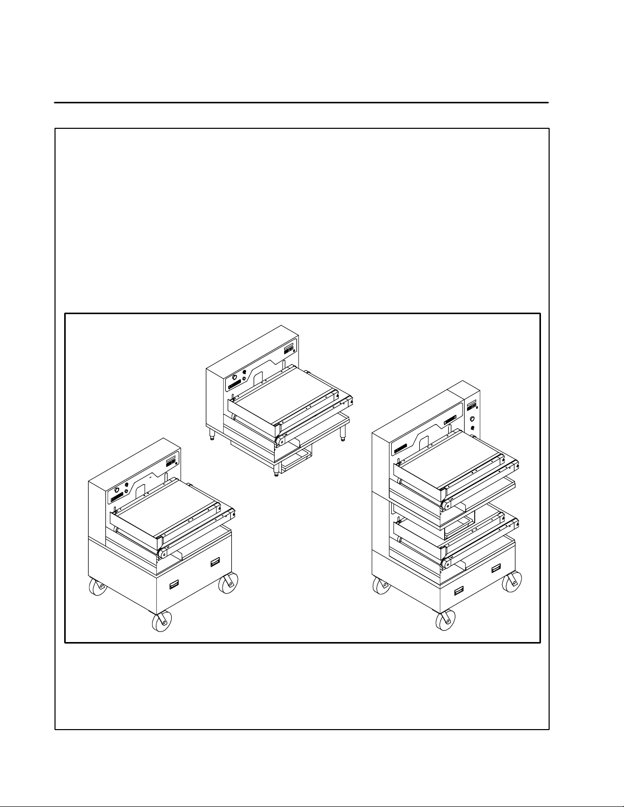
Blodgett Conveyor Grill Description
TheBlodgettConveyorGrillisamicroprocessor
controlled conveyorized belt cooking grill built by
Blodgett. The Blodgett Conveyor Grill uses two
Tef lon coated woven fiberglass belts each encircling an electrically heated aluminum cooking
platen. Food placed on the lower belt travels over
a preheat zone where the food is slightly thawed
(in the case of frozen food) and then between the
upper and lower platens where it is cooked on
both sides simultaneously. After cooking, the food
slides into a receiving pan. During the cooking
process, wipers remove excess grease from the
belts and collect it in a grease pan in the bottom
of the unit continuously.
The conveyor cooking technique assures consistent, dependable results. By closely controlling all
the variables --- cooking time, temperature, belt
speed and product contact pressure --- the possibility of improper cooking due to operator error or
inconsistency is greatly minimized. For the most
consistent cooking results use a portion controlled/consistent food product. The microprocessor controls six easy to use programmable menu
selections at the push of a button. It is the responsibility of the person(s) operating the machine to
periodically check that the food is properly
cooked.
TBG36-FM
Floor Model
TBG36-CM
Counter Model
TBG36-S
Stack Capacity
Model
2
Page 4
Specifications and Utility Requirements
DIMENSIONS AND WEIGHT SPECIFICATIONS
Introduction
TBG36-CM/AA
Counter Model
Width 35.75” (91 cm) 35.75” (91 cm) 43” (109 cm)
Height 31.5” (80 cm) 49.5” (126 cm) 69” (175 cm)
Depth 33.75” (86 cm)* 33.75” (86 cm)* 33.75” (86 cm)*
Weight
Crated
Uncrated
NOTE: * Includes 1.5” ( 3.81 cm) box on rear cover.
TBG36-CM/AA, TBG36-FM/AA and TBG36-S/AA ELECTRICAL SPECIFICATIONS
Hz Volts Phase Amps
60/50 208 3 50
60/50 220 3 47
60/50 240 3 43
60/50 440 3 24
680 lbs (308 kg)
580 lbs (263 kg)
TBG36-FM/AA
Floor Model
790 lbs (353 kg)
690 lbs (313 kg)
TBG36-S/AA
Stack Capacity Model
1545 lbs (701 kg)
1445 lbs (655 kg)
60/50 480 3 22
60/50 380 3 27
60/50 415 3 25
A 3 phase, 50/60 Hz, 3-wire grounded equipment branch circuit, permanently connected in accordance with applicable articles of ANSI/NFPA 70 (NEC code), is required. The stack capacity unit
requires tw o identical circuits.
Provision is made for 1-1/2” trade size conduit for incoming power. UL Listed reducing seals (donut
washers) will be required if a smaller size fitting is used.
Stack capacity (TBG36-S) model requires (2) power feeds, (1) for each cooking section. The stack
capacity design is not currently UL listed in Canada.
3
Page 5
Introduction
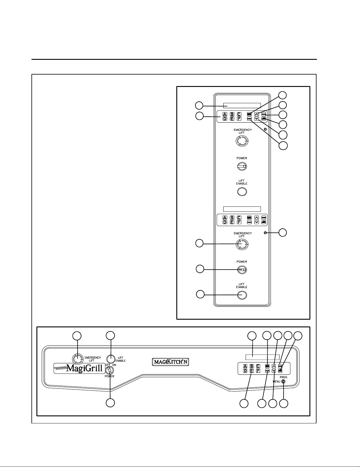
Controls Identification
1. SELECT/DISPLAY --- used to select the dis-
play information.
2. UP and DOWN ARROW --- u s e d i n p r o g r a m -
ming to increase/decrease selection choices.
3. ENTER --- used to enter a menu selection into
the current program.
4. OFF/CANCEL --- cancels the current menu so
another may be entered.
5. KEYSWITCH --- requires a key to change from
MENU mode to PROGRAM mode.
6. CLEAN --- raises the upper platen for thor-
ough cleaning.
7. MENU buttons --- used in the MENU mode to
load programming for products A through F.
Used in PROGRAM mode to select menu designations and product descriptions.
8. DISPLAY --- displays the menu a nd program
mode information selected.
9. EMERGENCY LIFT --- immediately raises the
upper platen to the clean position. Push and
turn to re-set/release button.
10. LIFT ENABLE --- a safety feature requiring the
operator to hold the button in while movingthe
platen to a cooking position after a programming adjustment or menu change.
11. MAIN POWER SWITCH --- An ON-OFF rotary
switch for emergency or convenience use
which controls all electrical power inside the
unit. When power is on, the display lights up.
8
7
9
11
10
1
2
3
4
2
6
5
TBG36-S Control
10
NEED NEW ARTWORK
11
TBG36-CM and TBG36-FM Control
4
1 2 3
89
7
4
526
Page 6

Startup Procedures
Platen Alignment
MECHANICAL INSTALLATION OR SERVICING
OF THIS MACHINE TO BE CARRIED OUT ONLY
BY PERSONNEL WHO HAVE BEEN AUTHORIZED BY BLODGETT TECHNICAL SERVICE.
NON-AUTHORIZED REPAIR OR INSTALLATION
WORK MAY VOID THE WARRANTY COVERAGE.
CALL BLODGETT TECHNICAL SERVICE AT
888-992-6624 TO CONFIRM AUTHORIZATION OF
SERVICE PERSONNEL TO WORK ON THIS UNIT,
TO CHECK THAT THE UNIT’S ELECTRICAL SUPPLY WIRING HAS BEEN COMPLETED BY A
QUALIFIED ELECTRICIAN PRIOR TO INSTALLATION OR TO SCHEDULE ANY INSTALLATION OR
SERVICE WORK ON THIS UNIT.
CHECKING SUPPLY VOLTAGE
Touch the multimeter probes to all three poles of
the definite purpose contactor to be sure all legs
are at the correct voltage and are reasonably
equal. Check each pole to ground the same way.
✍
Enter readings on startup form.
PLATEN ALIGNMENT
NOTE: Be sure the teflon belts are not installed
before performing the platen alignment.
After shipping, the unit will require checking and
may need re-squaring of the platens. Re-calibration of the linear potentiometer may also be necessary.
To check platen alignment
1. Place the unit in the clean mode as follows:
a.) Turnonthemainpowerswitchonthefront
panel.
b.) Check that the red Emergency Lift button,
on the left side of the unit, is released. Release the Emergency Lift button by turningittotherightasindicatedbythearrows on the button face.
c.) Place the keyswitch in the menu mode.
The key should be in the horizontal position. The display briefly flashes, scrolls
through several programming messages
and then reads [MENU?A].
d.) Press the CLEAN button. This raises the
upper platen approximately 4” to t he
clean position.
e.) Remove any remaining packaging from
between the platen.
2. Place the unit in the password mode (PSWD)
as follows:
a.) Turn the keyswitch to the PROGRAM posi-
tion. The key should be in the verticalposition. The display reads [PROG?A].
b.) Press the SELECT/DISPLAY button. The
display reads [PSWD?]
c.) Press the E NTER button and then press
the A button. The display reads [0:SE-
LECT MODEL].
d.) Press ENTER. Use the ARROW keys to
toggle the display to [TBG36”]. Then
pressENTER.Thisoperationisnecessary
to set the belt speed time constant since
thesamecontrollerisusedontwodifferent size models of TBG.
3. Set the calibration height as follows:
a.) Press the UP ARROW key once. The dis-
play reads [1:LIFT CAL].
b.) Press ENTER. The display reads [H=X.XXX],
the current position value.
NOTE: With the platen in the CLEAN posi -
tion this number will be greater
than 1.900.
c.) Adjust this value to .500 using the ARROW
keys while holding in the LIFT ENABLE
button. The last digit of this number may
fluctuate slightly.
5
Page 7

Startup Procedures
Platen Alignment
4. Test the spacing between the platens using
the 1/2” calibration rod (included with the
parts and accessories). If the gap is too small
for the rod to fit anywhere between the platens
adjust as follows:
a.) REMOVE THE ROD.
b.) While holding the LIFT ENABLE button,
use the ARROW keys to adjust the gap until the 1/2” rod just fits at the tightest point.
UP
1/2”
Calibration
Rod
DOWN
Figure 1
5. If the variation in the gap, using the 1/2” rod,
is no greater than ±0.016” (±1/64”) between
the front and the back of the platens or any of
the corners, no further alignment a djustment
is necessary and you may move to the Height
Calibration procedure.
To adjust platen al ignment if necessary
1. If platen alignment is necessary, use two 7/16”
wrenches as shown in Figure 1 to turn the nut/
bolt assemblies on each of the four corners of
the upper and lower platen assemblies until
the platens are aligned.
2. If you are unable to align the platens satisfactorily at the 1/2” setting, it may be necessary
to carry out a rough alignment at a 3” height.
When aligning at the 1/2” setting it is difficult
or impossible to adjust the two rear bolt/nut
pairs on the upper platen, so setting the alignment at this larger gap allows hand access to
all of the nut/bolt pairs.
a.) Use a piece of 3” rigid plastic pipe cut
squarely or other block of material of the
right size. Adjust all the nut/bolt pairs so
they are in the middle of their travel range.
b.) Raise the upper platen to allow the 3”
gauge to fit in and follow the instructions
for t he 1/2” rod.
c.) When the 3” gauge fits uniformly every-
where between the platens, repeat the
calibration with the 1/2” rod to fine tune.
d.) When the 1/2” rod fits uniformly at allspots
between the platens, the alignment process is complete.
NOTE: DO NOT discard the 1/2” rod, it may be
necessary for future servicing of the unit.
✍
Check off platen alignment on startup form
upon completion of procedure.
Tips for platen alignment
D
Make small adjustments (1/2 turns). Re-check
the entire platen for squareness frequently.
D
Always turn the nut and bolt together as a unit
wherepossible(youwillonlybeabletoturnthe
assembly using nut on the inner nut/bolt assemblies).
D
It may be necessary to use two wrenches to
loosen the nut slightly while holding the bolt
head if the nut/bolt assembly is too tight to turn.
D
If the nut/bolt will not turn as an assembly, try replacing the locking nut with a new one.
D
Always make sure the bolt heads and nuts
are both tight against the platen frame mem bers during adjustment and are snug after final alignment.
D
Do not continue to turn a nut/bolt assembly if it
has bottomed out at it’s limit in the frame assembly or you may break the adjusting bolt assembly.
6
Page 8

ADJUSTING PLATEN HEIGHT AND LINEAR
POTENTIOMETER
!
NOTE: If the display still reads .500
016”, then
no linear potentiometer calibration is necessary, and you may move on to checking
the thermocouples.
To adjust the platen height
1. Removetherearcover.
2. Loosen the two locknuts on the potentiometer
shaft using the 5/16” combination wrenches.
3. When you lower the locknuts on the shaft, the
display value goes down. When you raise the
locknuts the display value goes up. When the
display reads .500 ± 010”, hold the bottom nut
still and tighten the top nut against it.
NOTE: Check the display while tightening to
ensure that the value doesn’t change.
✍
Check off Height Calibration on startup form
upon completion of procedure.
Startup Procedures
Height Calibration
Linear
Potentiometer
Plunger Shaft
Plunger Weight
Adjustment Nuts
Moving
Reference Bracket
Figure 2
WARNING!!
Be very careful, you will be working with
metal wrenches in a live voltage area. If
the unit y ou are working on does not have
a protective plastic sheet over the definite
purpose contactor area, you should make
one out of plastic,cardboardor some other non-conductive material.
7
Page 9

Startup Procedures
Thermocouple Continuity Test
1. De-energize the unit.
2. Remove the 18 pin Molex plug from connector
J-4 of the controller board.
3. Check for continuity across each of the pairs
of thermocouples. If a thermocouple is open
(no continuity), check all connections and replace/repair the thermocouple a s necessary.
4. Check each of the pins for a short to ground.
If there is a short to ground, replace or repair
the thermocouple in question.
✍
Check off Thermocouple Continuity Test on
startup form upon completion of procedure.
J Type Thermocouple
(ambient)
Bottom Heat, Oufeed, Red ( --- )
Bottom Heat, Infeed, Red (--- )
Top Heat, Oufeed, Red (--- )
Top Heat, Infeed, Red (---)
Pinout Diagram for the Thermocouple Connector J4
Figure 3
Bottom Heat, Oufeed, White (+)
Bottom Heat, Infeed, White (+)
Top H eat, Oufeed, White (+)
Top H eat, Infeed, White (+)
Figure 4
8
Page 10

Startup Procedures
Assembly for Testing
IDLE ROLLERS
1. Replace the rear covers if they were previously
removed and energize the Blodgett Conveyor
Oven.
2. Slip the idle roller into the slots on the idle roller
adjustment blocks.
Idle Roller
Figure 5
COOKING BELTS
1. Slide the cooking belts over the roller on the
platen deck s. The longer belt goes on the lower platen deck. See Figure 6.
2. After the belts are installed, back the adjusting
bolts out until there is at least a 1/8” gap between the bolt head and the plastic idle roller
bearing block. See Figure 7. The belts will now
have tension on them.
3. Re--check periodically after use to see that
there is still a 1/8” gap, since the belts may
stretch slightly over time.
Upper
Belt
Lower
Belt
3. The idle roller adjustment blocks are spring
loaded. The adjusting bolts must be turned in
all t he way in order to install or remove the
cooking belts on the platen a ssemblies. Use
the Tee Handle Tool supplied for this adjustment.
Figure 6
End view of idle roller
Approximately 1/8” gap
between bolt head and
idle roller tension block
during normal operation
Figure 7
9
Page 11

Startup Procedures
Complete Functional Testing
PROGRAMMING FLOW CHART
Power Switch
ON
Turn
KEYSWITCH
to vertical
position
Display reads
PROG?A
NO
YES
ARROW KEYS
Belt Speed
Press ENTER
display reads
A
Press
to set
PH = BH
UP
T=XX.XX
DOWN
CHANGE SPELLING
Select letter
with
ARROW KEYS
L E T T E R K E Y A --- F
youwishto
Top H e a ter
Press ENTER
display reads
ARROW KEYS
to set temp
Bottom Heater
Press ENTER
display reads
TBG60
ARROW KEYS
to set temp
Press the
program
TH = XXX
Press
BH = XXX
Press
UP
DOWN
TBG36
DOWN
ARROW KEYS
to set time
Height Between
Platens
Change
Food Product
Descriptions
Press ENTER
display reads
H=XX.XX
ARROW KEYS
to set height
Press ENTER
display reads
FOOD PRODUCT
Press
Press
Change
product
spelling?
UP
UP
DOWN
DOWN
YES
CONTINUE
SPELLING
Press
ENTER to lock
in letter
DONE
Press
SELECT DISPLAY
Display reads
SAVE A>F
Press ENTER
display reads
SAVING
Display reads
PROG?A
Finished
programming
Preheater
Press ENTER
display reads
PH = XXX
A
UP
NO
NOTES:
_
All temperature setting must be less than or equal to 450
Platen height (H = X.XXX) must be less than or equal to 1.900” and greater than or
equal to 0.100”
Belt speed (T = X.XXX) must be less than or equal to 4 minutes and great than or equal
to 35 seconds.
F
10
Page 12

START/POWER
switch on
Turn KEY to program
(vertical position)
Press SELECT DISPLAY
Display reads PSWD?::
Unlocks Display
Press ENTER then A
Startup Procedures
Complete Functional Testing
CALIBRATION FLOW CHART
Page 1 of 3
Display reads
0:SELECT MODEL
Press ARROW key
to continue
programming
display reads
1:LIFT CAL
Press ARROW key
to continue
programming
2:CJ CAL
Press ARROW key
to continue
programming
Display reads
3:TEMP CAL
Press
A button
Display
reads
Change linear pot
calibration
Calibrate thermocouple
cold junctions
When finished press
OFF/CANCEL
Calibrate 3 platens
to external reference
Press ENTER
display reads
TBG36 or TBG60
When finished
Press ENTER
Press ENTER
display reads
H=X.XXX
When finished
Press
OFF/CANCEL
Press ENTER
display reads
CJ=XX
Press ENTER
to save
Press ENTER
display reads
SET = 400
Press ARROW
keys to
select
Press ARROW keys
and LIFT ENABLE to
set height. Calibrate with
known dimension
Press ARROW keys
to adjust. Use external
meter for calibration
Press ARROW
keys to set
temperature
Press ARROW key
to continue
programming
A
Press
OFF/CANCEL
Set
TH = SET
BH = SET
PH = SET
with ARROW keys
Set each
temperature by
pressing ENTER
11
Scroll display with
SELECT DISPLAY
compare
temperature with
external meter
Press ENTER
3 platens heat
to temperature
and stabilize
Page 13

Startup Procedures
Complete Functional Testing
CALIBRATION FLOW CHART
A
Change all cooking
menu parameters while
operating
Display reads
4:TEST COOK
Page 2 of 3
Press ENTER
then a menu key
A --- F
Press ENTER and
LIFT ENABLE
release ENTER
(hold LIFT ENABLE
until platen stops moving)
Display reads
T = XX:XX
(counts down until up
to temperature)
belts start moving
Press ARROW key
to continue
programming
Display reads
5:SET TOPHEAT
Press ARROW key
to continue
programming
Display reads
6:SET BOT HEAT
Press ARROW key
to continue
programming
Display reads
7:SET PREHEAT
Change top
platen temperature
(actual platen temp)
Press OFF/CANCEL
Change bottom
platen temperature
(actual platen temp)
Press OFF/CANCEL
Change preheat
platen temperature
(actual platen temp)
Default to old setting
Press OFF/CANCEL
Save changes
press ENTER
Press ENTER
display reads
T = XXX
twice to exit
Press ENTER
display reads
T = XXX
twice to exit
Press ENTER
display reads
T = XXX
When
done
press
OFF/CANCEL
Press OFF/CANCEL
display reads
TH XXX
(current platen temp)
Press OFF/CANCEL
display reads
BH XXX
(current platen temp)
Press OFF/CANCEL
display reads
PH XXX
(current platen temp)
Press SELECT/DISPLAY
Use ARROW keys to select
parameter to change
TH BH PH T H
(change to desired setting)
Press ARROW keys
to adjust temperature
Press ENTER
display reads
T = XXX
(showns platens temp)
Press ARROW keys
to adjust temperature
Press ENTER
display reads
T = XXX
(showns platens temp)
Press ARROW keys
to adjust temperature
Press ARROW key
to continue
programming
Press OFF/CANCEL
twice to exit
Press ENTER
display reads
T = XXX
(showns platens temp)
B
12
Page 14

B
Display reads
8:SET TIME
FOR TECHNICIAN ONLY
Shows main control board is
picking up magnetic speed
control output
Press ENTER
display reads
T = X:XX
(shows a time value)
Startup Procedures
Complete Functional Testing
CALIBRATION FLOW CHART
Page 3 of 3
Press ENTER
display reads
S=XXXXX
(shows fluctuating number)
pick up is working “OK”
Press ARROW key
to continue
programming
Display reads
SET HEIGHT
Press ARROW key
to continue
programming
Display reads
10:STOP ALL
Press ARROW key
to continue
programming
Display reads
11:DEFAULT MENU
Press ARROW key
to continue
programming
Obsolete Function
LIFT CAL does the
same function
Discontinues all
password setting
8through10
Only to change all
menus to preset variables
(current position)
Press
OFF/CANCEL
twice to exit
Press ENTER
display reads
P=X.XXX
When finished
display reads
Press ENTER
to change
Press ENTER
to change
P = X.XXX
Press OFF/CANCEL
twice to exit
Press OFF/CANCEL
display reads
P = X.XXX
(adjust to desired height)
Press ENTER
platen will adjust
Press OFF/
CANCEL
to exit
Scroll through the
following
12:EE WORD
13:EE BYTE
14:SET CHECKSUM
FINISHED
RESTRICTED
DO NOT ACCESS
FOR ENGINEERING
ONLY
13
Page 15

Startup Procedures
Complete Functional Testing
OPERATIONAL FLOW CHART
Turn on
MAIN POWER
SWITCH
(turn knob to right)
A
Release
EMERGENCY LIFT
if set
(turn knob to right)
Turn
KEYSWITCH
to Menu
(horizontal position
display reads
MENU?A
Press (1) desired
menus selection
button A --- F
Press and hold
ENTER and LIFT ENABLE
buttons at the same time
oven beeps
Release ENTER
hold LIFT ENABLE
until upper platen lowers
to cooking height and
stops
Push Red
EMERGENCY LIFT
button
Cooking cycle
complete
T=00:00
Push OFF/CANCEL
display reads
remaining time
T=XX:XX
Push
OFF/CANCEL
Finish
select new program
Display reads
STANDBY
platens preheat and
counts down from 15 min.
T=XX:XX
Roller and belts start
moving
Blodgett Conveyor Oven
ready to cook
(display scrolls cooking
description)
A
14
Page 16

Startup Procedures
Complete Functional Testing
Checking the cooking consistency
1. Press OFF/CANCEL twice.
2. Press A and ENTER.
3. Place the 9 fresh bread slices on the infeed of
the lower platen (3 rows and 3 columns). See
Figure 8.
4. All nine slices should emerge evenly done on
all sides with no variations in appearance. A
variation in appearance between the tops and
bottoms of the slices indicates a possible
problem with temperature control or height
calibration. A variation between columns or
rows indicates a possible platen alignment
problem.
✍
Report on cooking performance on startup
form upon completion of test.
Back of Unit
BELT TRAVEL
Exiting the functional testing
1. Press OFF/CANCEL.
2. Wait for the cooking cycle to time out.
3. Press CLEAN.
4. Turntheredpowerswitchtotheoffposition,
and disconnect the power.
Installation checklist
Complete and return the startup form to Blodgett
Technical Service.
OUTFEED
Back Row
Middle Row
INFEED
Front Row
Lower Belt Test Cooking Pattern for Sliced Bread
Figure 8
15
 Loading...