

Page 1

TBG36-CM, TBG36-FM AND TBG36-S
ELECTRIC CONVEYOR GRILL
INSTALLATION -- OPERATION -- MAINTENANCE
BLODGETT OVEN COMPANY
www.blodgettcorp.com
50 Lakeside Avenue, Box 586, Burlington, Vermont 05402 USA T elephone (800) 331-5842, (802) 860-3700 Fax: (802)864-0183
PN G0171 Rev A (7/01)
E 2001 --- G.S. Blodgett Corporation
Page 2

IMPORTANT
WARNING: IMPROPER INSTALLATION, ADJUSTMENT,
ALTERA TION, SERVICE OR MAINTENANCE CAN CAUSE
PROPERTY DAMAGE, INJURY OR DEATH. READ THE INSTALLATION, OPERATING AND MAINTENANCE INSTRUCTIONS THOROUGHLY BEFORE INSTALLING OR
SERVICING THIS EQUIPMENT
FORYOURSAFETY
Do not store or use gasoline or other flammable vapors or
liquids in the vicinity of this or any other appliance.
The information contained in this manual is important for the proper
installation, use, and maintenance of this g rill. Adherence to these
procedures and instructions will result in satisfactory cooking results and long, trouble free service . Please read this manual carefully
and retain it for future reference.
Errors: Descriptive, typographic or pictorial errors are subject to correc-
tion. Specifications are subject to change without notice.
Page 3

THE REPUTATION YOU CAN COUNT ON
For over a century and a half, The Blodgett Oven Company has been building
ovens and nothing but ovens. We’ve set the industry’s quality standard for all
kinds of ovens for every foodservice operation regardless of size, application
or budget. In fact, no one offers more models, sizes, and oven applications
than Blodgett; gas and electric, full-size, half-size, countertop and deck, convection, Cook’n Hold, Combi-Ovens and the industry’s highest quality Pizza
Oven line. For more information on the full line of Blodgett ovens contact your
Blodgett representative.
Page 4

Your Service Agency’s Address:
Model:
Serial Number:
Your grill was installed by:
Your grill’s installation was checked by:
Page 5

Table of C o n t e n t s
Introduction
Blodgett Conveyor Grill Description 2.................................
Specifications and Utility Requirements 3.............................
Installation
Delivery and Inspection 4...........................................
Agency Approvals 6................................................
Grill Ventilation, Clearances and Installation Requirements 7.............
Blodgett Conveyor Grill Assembly 8..................................
Upper Grease Wiper Box 8.......................................
Lower Grease Wiper Box 8.......................................
Drain Pan 9....................................................
Optional Outfeed Slide and Receiving pan 9........................
Optional Infeed Slide 9..........................................
Grease Pan and Crumb Tray 10....................................
Operation
Control Panel 11....................................................
Program Mode 12...................................................
Menu Mode 14.....................................................
Menu Development 15...............................................
Grilling Tips 16.....................................................
Maintenance
Cleaning 18........................................................
Cleaning the Grill 18..............................................
Cleaning the Cooking Belts 19.....................................
Troubleshooting 20..................................................
Page 6
Introduction
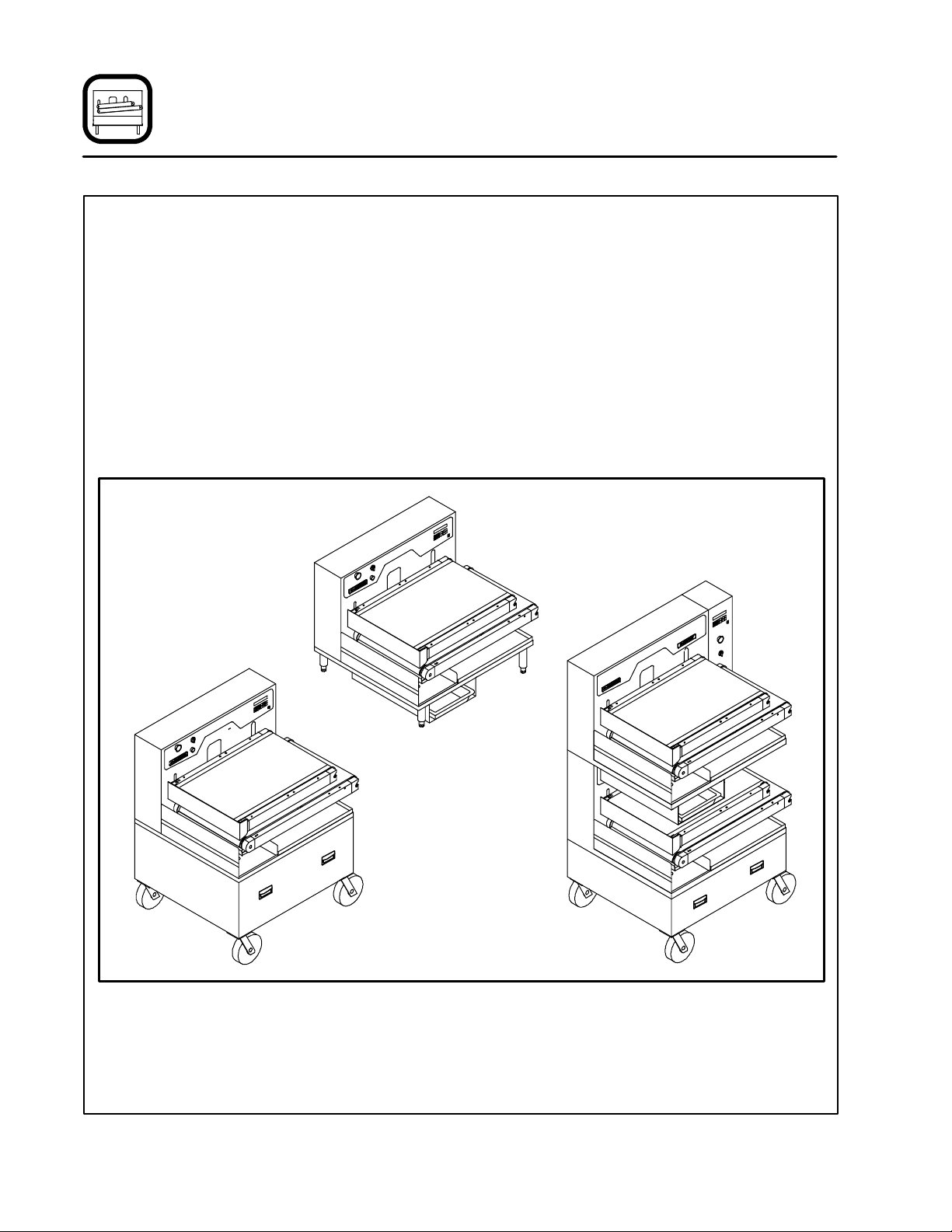
Blodgett Conveyor Grill Description
TheBlodgettConveyorGrillisamicroprocessor
controlled conveyorized belt cooking grill built by
Blodgett. The Blodgett Conveyor Grill uses two
Tef lon coated woven fiberglass belts each encircling an electrically heated aluminum cooking
platen. Food placed on the lower belt travels over
a preheat zone where the food is slightly thawed
(in the case of frozen food) and then between the
upper and lower platens where it is cooked on
both sides simultaneously. After cooking, the food
slides into a receiving pan. During the cooking
process, wipers remove excess grease from the
belts and collect it in a grease pan or bucket in the
bottom of the unit continuously.
The conveyor cooking technique assures consistent, dependable results. By closely controlling all
the variables --- cooking time, temperature, belt
speed and product contact pressure --- the possibility of improper cooking due to operator error or
inconsistency is greatly minimized. For the most
consistent cooking results use a portion con trolled/consistent food product. The microprocessor controls six easy to use programmable menu
selections at the push of a button. It is the responsibility of the person(s) operating the unit to periodically check that the food is properly cooked.
TBG36-FM
Floor Model
TBG36-CM
Counter Model
TBG36-S
Stack Capacity
Model
Figure 1
2
Page 7
Introduction
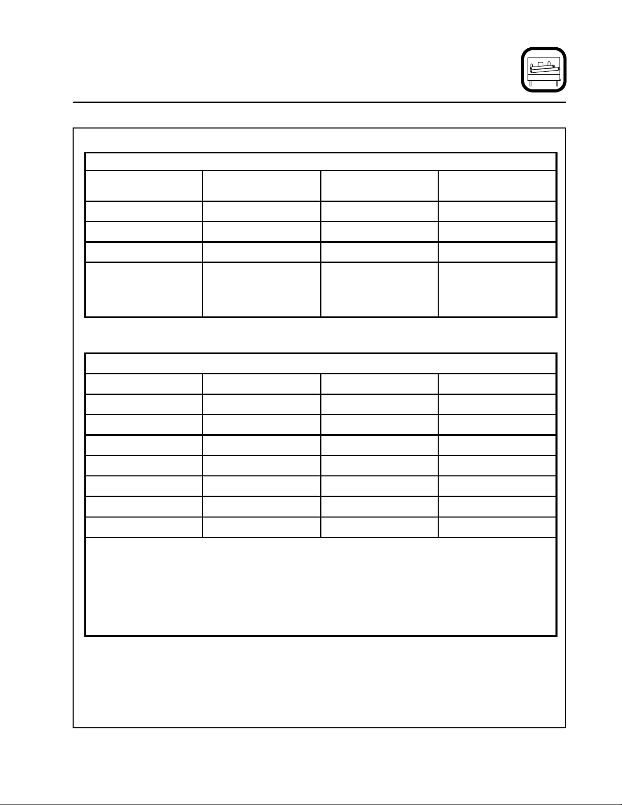
Specifications and Utility Requirements
DIMENSIONS AND WEIGHT SPECIFICATIONS
TBG36-CM/AA
Counter Model
Width 35.75” (91 cm) 35.75” (91 cm) 43” (109 cm)
Height 31.5” (80 cm) 49.5” (126 cm) 69” (175 cm)
Depth 33.75” (86 cm)* 33.75” (86 cm)* 33.75” (86 cm)*
Weight
Crated
Uncrated
NOTE: * Includes 1.5” ( 3.81 cm) box on rear cover.
TBG36-CM/AA, TBG36-FM/AA and TBG36-S/AA ELECTRICAL SPECIFICATIONS
Hz Volts Phase Amps
60/50 208 3 50
60/50 220 3 47
60/50 240 3 43
60/50 440 3 24
680 lbs (308 kg)
580 lbs (263 kg)
TBG36-FM/AA
Floor Model
790 lbs (353 kg)
690 lbs (313 kg)
TBG36-S/AA
Stackable Model
1545 lbs (701 kg)
1445 lbs (655 kg)
60/50 480 3 22
60/50 380 3 27
60/50 415 3 25
A 3 phase, 50/60 Hz, 3-wire grounded equipment branch circuit, permanently connected in accordance with applicable articles of ANSI/NFPA 70 (NEC code), is required. The stack capacity unit
requires tw o identical circuits.
Provision is made for 1-1/2” trade size conduit for incoming power. UL Listed reducing seals (donut
washers) will be required if a smaller size fitting is used.
Stack capacity (TBG36-S) model requires (2) power feeds, (1) for each cooking section. The stack
capacity design is not currently UL listed in Canada.
3
Page 8
Installation
Delivery and Inspection
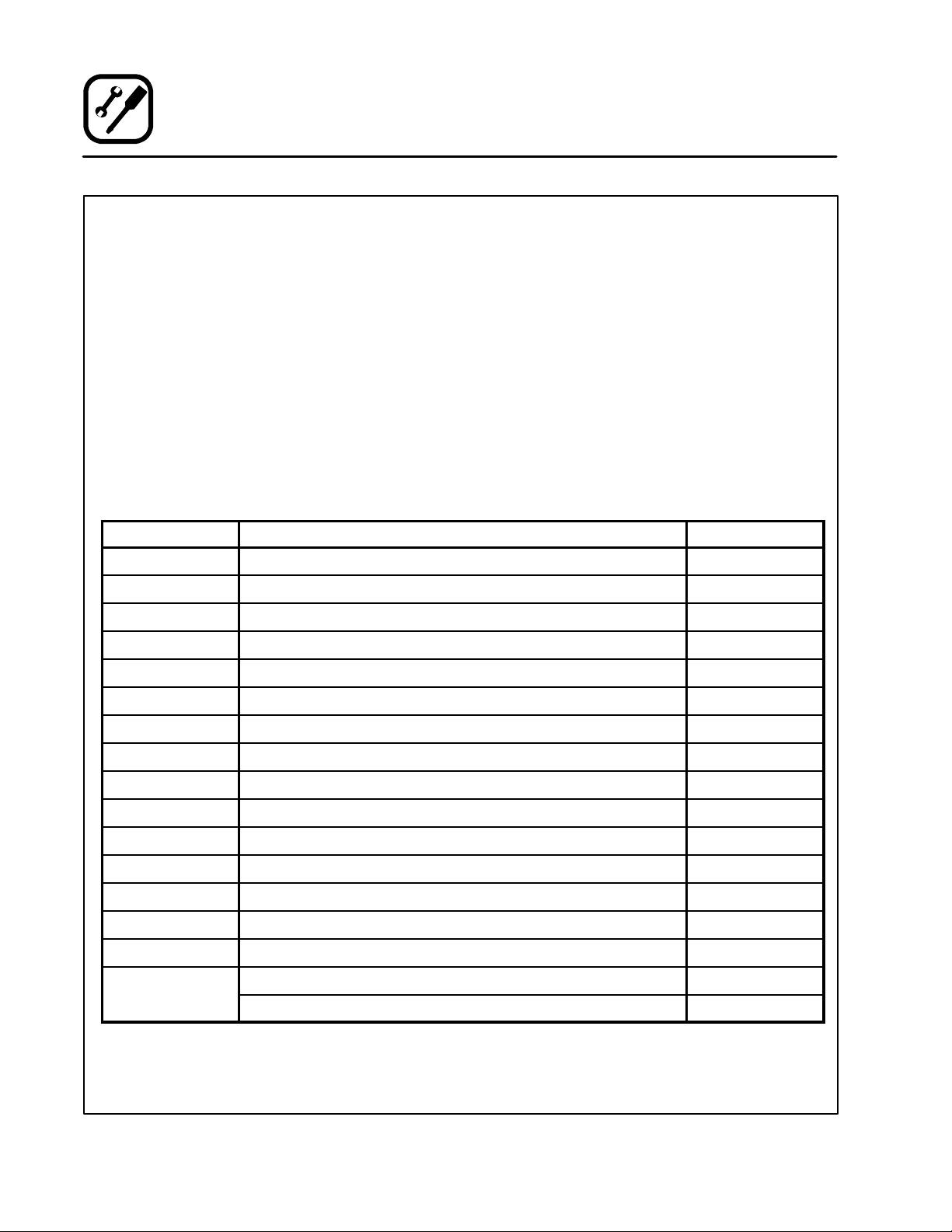
Upon delivery of your Blodgett Conveyor Grill:
Inspect the shipping container for external damage. Any evidence of damage should be noted on
the delivery receipt and the bill of lading, which
must be signed by the driver. Uncrate the Blodgett
Conveyor Grill a nd check for internal damage.
Inspect the unit immediately upon receipt. Do not
sign off on shipment until the packaging has been
removed and the unit has been inspected for damage. Blodgett cannot assume responsibil i ty for loss
or damage suffered in transit. The carrier assumed
full responsibility for delivery in good order when the
shipment was accepted. We are, however , prepared
to assist you in filing a claim if necessary.
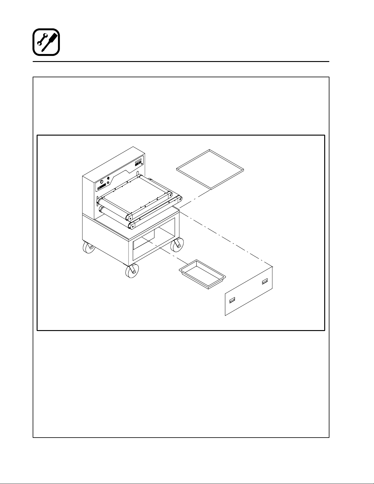
ITEM
1 Blodgett Conveyor Grill, Model TBG36 (TBG36-FM shown) 1
2 Idle Rollers 2
3 UpperConveyorBelt 2
4 LowerConveyorBelt 2
5 Drain Pan 1
DESCRIPTION QTY.
Unpacking the unit:
Open all parts boxes carefully. DO NOT USE A
BLADECUTTERORKNIFE!One of the boxes
contains the woven glass Teflon impregnated
cooking belts which can easily be cut and damaged or destroyed. The warranty will not cover accidental cutting of belts during unpacking.
Remove all shipping bands and loose packaging
material from the unit. Remove all loose parts from
theupperandlowerplatenassemblies.Donot
discard the shipping crate or materials until installation is complete and unit is operating.
Check that all of the following parts have been received. Contact Blodgett immediately if any of the
components are damaged or missing.
6 Product Receiving Pan 1
7 Grease Pan / Bucket 1
8 Crumb Tray 1
9 Upper Wiper Box 1
10 Lower Wiper Box 1
11 Controller Programming Keys 2
12 Owner’s Manual 1
13 Door Panel (FM and S models only) 1
14 9/16” Tee Handle Wrench 1
15 1/2” Calibration Rod 1
Items not
shown
Wiper Blades 2
Bacon Scraper Blade 1
4
Page 9

Installation
Delivery and Inspection
TBG36-S has two platen sets for cooking on a single base with casters (quantities of all parts are doubled for TB G36 -S models)
TBG36 -FM floor model shown, TBG36-CM counter model has legs in place of the base with casters,
Figure 2
5
Page 10
Installation
Agency Approvals
THE INSTALLATION INSTRUCTIONS CONTAINED HEREIN ARE FOR THE USE OF QUALIFIED INSTALLATION AND SERVICE PERSONNEL
ONLY. INSTALLATION OR SERVICE BY OTHER
THAN QUALIFIED PERSONNEL MAY RESULT IN
DAMAGE TO THE OVEN AND/OR INJURY TO
THE OPERATOR.
Qualified installation personnel are individuals, a
firm, a corporation, or a company which either in
person or through a representative are engaged
in, and responsible for:
D
the installation of electrical wiring from the electric meter, main control box or service outlet to
the electric appliance.
Qualified installation personnel must be experienced in such w ork, familiar with all precautions
required, and have complied with all requirements
of state, national and/or local authorities having jurisdiction.
U.S. and Canadian installations
The unit must be wired in compliance with ANSI/
NFPA 70 NEC (the National Electrical Code) and
all local codes and ordinances required where the
Blodgett Conveyor Grill is installed.
General export installations
Installation must conform with Local and National
codes and installation standards. Local installation codes a nd/or requirements may vary. If you
have any questions regarding the proper installation and/or operation of your Blodgett Conveyor
Grill, please contact your local distributor. If you do
not have a local distributor, please call Blodgett
Technical Service at 0011-888-992-6624.
117F LISTED
COMMERCIAL COOKING APPLIANCE
TBG36-S not currently listed in Canada
6
Page 11

Installation
Grill Ventilation, Clearances and Installation Requirements
VENTILATION
While the Blodgett Conveyor Grill requires less
ventilation than a conventional griddle, a power
vented hood of at least 525 CFM capacity is required for proper performance and safety of one
TBG36.
CLEARANCES
The unit is designed for 0” clearance on t he sides
and back, however, it is wise to allow more clearance for ease of operation, cleaning and maintenance.
INSTALLATION REQUIREMENTS
A UNIT INSTALLATION AND CALIBRATION SERVICE IS PROVIDED FOR AND IS REQUIRED BEFORE USING THE BLODGETT CONVEYOR
GRILL FOR THE FIRST TIME. UNIT INSTALLATION AND CALIBRATION IS TO BE CARRIED
OUT ONLY BY SERVICE AGENTS OR PERSONNEL AUTHORIZED BY BLODGETT TECHNICAL
SERVICE TO PERFORM THIS WORK. IF ONE
HAS NOT YET BEEN PERFORMED ON YOUR
UNIT, CONTACT BLODGETT TECHNICAL SUPPORT AT 888-992-6624 TO ARRANGE FOR AN
ASAP SERVICE VISIT.
WARNING!!
DO NOT use the unit befo re this service
has been performed. Use of the unit prior
to this or installation or servicing by other
than Blodgett Technical Service authorized service agencies or personnel may
void warranty coverage.
7
Page 12
Installation
Blodgett Conveyor Grill Assembly
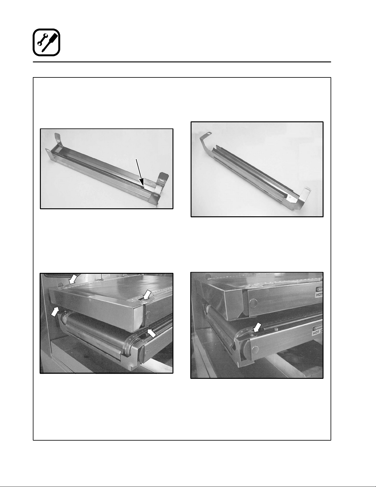
UPPER GREASE WIPER BOX
1. Before installing the upper grease wiper box,
slidetherubberwiperbladeintoit’sslotinthe
wiper box. Slide the long edge in first. See
Figure 3.
Wiper
Blade
Figure 3
2. Snap the four spring fingers of the upper wiper
box over the screws in the end frame. See
Figure 4. The long fingers go on top.
NOTE: The wiper box opens towards the
back to allow the grease to flow to the
rear of the unit.
LOWER GREASE WIPER BOX
1. Before installing the lower wiper box, insert
the rubber wiper blades into their slots in the
wiper box. See Figure 5.
Figure 5
2. Install the lower wiper box by hanging the slots
in the mounting brackets onto the screw
heads on top of the deck. See Figure 6. The
wiper box rides against the belt by its own
slung weight.
Figure 4
Figure 6
8
Page 13
Installation
Blodgett Conveyor Grill Assembly
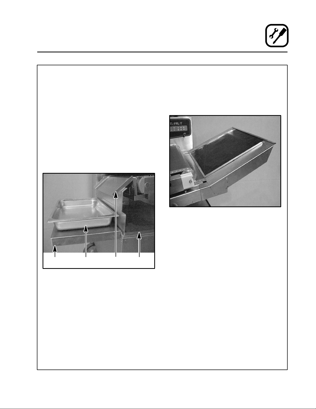
DRAIN PAN
1. Place the drain pan into position at the bottom
left of the unit .
OPTIONAL OUTFEED SLIDE AND RECEIVING
PAN
1. Slide the outfeed slide onto the left hand edge
of the drain pan and push it to the back. Be
sure the slot on the baffle fits tightly onto the
side of the drain pan.
2. Attach the removable shelf to the left side of
thegrillbaseandseatitfirmlyontothebase
rim.
3. Place a product receiving pan up to 4-1/2”
deep on the shelf and under the lower edge of
the slide to collect the finished foods.
OPTIONAL INFEED SLIDE
The infeed slide option allows food product to be
loaded on a slide to feed by itself so other work
may be done while cooking.
1. Slip the infeed slide onto the lower platen rails
at the infeed end. Push until it seats fully.
Figure 8
Removable
Shelf
Receiving
Pan
Figure 7
Outfeed
Slide
Drain Pan
9
Page 14
Installation
Blodgett Conveyor Grill Assembly
GREASE PAN AND CRUMB TRAY
1. Place the grease pan (grease bucket for floor
models) in its compartment under the front of
the unit, making sure it is located beneath the
downspout tube of the drain trough.
2. Slide the crumb tray under the lower platen on
the right side of the unit.
3. Install the door panel on the front of the lower
compartment (TBG36-FM and TBG36-S only).
Crumb Tray
Figure 9
Grease Pan
Door Panel
10
Page 15

Operation
Control Panel
THE INFORMATION CONT AINED IN THIS SECTION IS PROVIDED FOR THE USE OF QUALIF IED
OPERA TIN G PERSONNEL. QUALIFIED OPERATING PERSONNEL ARE THOSE WHO HAVE CAREFULLY READ THE INFORMATIO N CONTAINED IN
THIS MANUAL, ARE FAMIL IAR WITH THE FUNCTIONS OF THE OVEN AND/OR HAVE HAD PREVIOUS EXPERIENCE WITH THE OPERATION OF
THE EQUIPMENT DESCRIBED. ADHERENCE TO
THE PROCEDURES RECOMMENDED HEREIN
WILL ASSURE THE ACHIEVEMENT OF OPTIMUM
PERFORMANCE AND LONG, TROUBLE-FREE
SERVICE.
Please take the time to read the following operating instructions. They are the key to the successful
operation of your Blodgett Conveyor Grill.
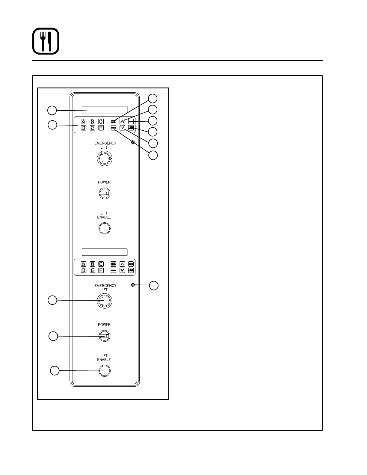
CONTROL DESCRIPTIONS
NOTE: For TBG36-CM and TBG36-FM, refer to
Figure 10. For TBG36-S, refer to Figure 11.
1. SELECT/DISPLAY --- used to select the dis -
play information.
2. UP and DOWN ARROW --- u s e d i n p r o g r a m -
ming to increase/decrease selection choices.
3. ENTER --- used to enter a menu selection into
the current program.
4. OFF/CANCEL --- cancels the current menu so
another may be entered.
5. KEYSWITCH --- requires a k ey to change from
MENU mode to PROGRAM mode.
6. CLEAN --- raises the upper platen for thor-
ough cleaning.
7. MENU buttons --- used in the MENU mode to
load programming for products A through F.
Used in PROGRAM mode to select menu designations and product descriptions.
8. DISPLAY --- displays the menu and program
mode information selected.
9. EMERGENCY LIFT --- immediately raises the
upper platen to the clean position. Push and
turn to reset/release button.
10. LIFT ENABLE --- a safety feature requiring the
operator to hold the button in while movingthe
platen to a cooking position after a programming adjustment or menu change.
11. MAIN POWER SWITCH --- An ON-OFF rotary
switch for emergency or convenience use
which controls all electrical power inside the
unit. When power is on, the display lights up.
10
11
NEED NEW ARTWORK
TBG36-CM and TBG36-FM Control
Figure 10
11
89
1 2 3
5267
4
Page 16
Operation
Program Mode
8
7
9
PROGRAMMING
1
2
3
4
2
6
5
PROGRAM mode is used to define six cooking
programs A through F. It can only be entered by
use of the keyswitch. To use the PROGRAM mode
follow the steps below:
Select Desired Menu to program:
1. Turn on the unit MAIN POWER SWITCH (11).
2. Turn the KEYSWITCH (5) to the PROGRAM
position. The display reads [PROG?A].
3. Press the letter of the desired MENU KEY (7).
4. Press ENTER (3) to select the desired menu.
NOTE: If the display reads [TBG36?], the
model size has not been selected.
Press ENTER (3) to select the 36”
model size.
Setting the Cooking Temperature
NOTE: The maximum cook temperature is 450
The minimum cook temperature is 70
1. The display reads [TH=xxx], indicating that the
top heater (TH=) is set for xxx_F. U s e t h e A R ROW (2) keys to raise or lower the temperature
setting for the upper platen.
2. Press ENTER (3) to choose that temperature
and enter it into the program.
3. The display now reads [BH=xxx], indicating that
the bottom heater (BH=) is set for xxx_F. U s e
the ARROW (2) keys to raise or lower the temperature setting for the upper platen.
4. Press ENTER (3) to choose that temperature
and enter it into the program.
Setting the Cook Time
_
_
F.
F.
11
10
TBG36-S Control
Figure 11
NOTE: The maximum cook time is 10:00 minutes.
The minimum cook time is 0:30 seconds.
NOTE: This is the actual cooking time (the time
spent between the upper and lower platens) not the total time to travel the length
of the lower conveyor belt.
1. The display now reads [T=xx.xx]. This indicates the current cooking time is xx.xx minutes/seconds. Use the ARROW (2) keys to enter the desired cooking time.
2. Press ENTER (3) to enter the new cooking
time into the program.
12
Page 17

Operation
Program Mode
Setting the Platen Height
NOTE: The maximum platen height is 1.900”. The
minimum platen height is 0.100”.
1. The display now reads [H=x.xxx]. This indi-
cates the current distance between platens in
inches and thousandths. Use the ARROW (2)
keys to change this value.
2. Press ENTER (3) to enter the new platen
height into the program.
Setting the Product Description
If you do not want to change the product description:
1. Press SELECT DISPLAY (1) followed by ENTER to save the program.
To change the product description:
1. If the display now reads [CHICKEN],thisisthe
product description for the menu you are now
modifying. The text is changed one letter at a
time using the ARROW (2) keys for the letter
that is blinking.
2. Press ENTER (3) to select t hat character and
move onto the next letter. Move from one char acter to the next using the ENTER (3) key until
you reach the end.
3. You will need to blank out any unwanted/extra
letters before saving. The blank space is located a few characters after the z.
4. Press SELECT DISPLAY (1) t o select and store
the whole word (product description).
Saving the New Menu Programming
1. When your menu programming session is
complete, press ENTER (3) to save the new
program. The display reads [SAVING].
PROGRAMMING TIPS
D
Once a setting has been entered, you cannot go
back to change it during the current programming session. If you make a mistake, finish programming any desired variables and save the
program. Go back into the programming mode
for that menu, cycle through the variables with
the ENTER (3) button and correct the desired
entry. Press ENTER (3) to save the program
again.
D
Do not enter a platen height of less than 0.100”
or grea ter than 1.900”.
D
Do not enter cooking t imes (belt speeds) of less
than 30 seconds or more than 10 minutes.
13
Page 18

Operation
Menu Mode
Menu mode allows the user to select one of the six
programmed product settings. To operate the unit
in the MENU mode simply follow the steps below:
Select Desired Menu to Run
1. Turn on the MAIN POWER SWITCH (11).
2. T urn the KEYSWITCH (5) to the MENU position.
3. The display reads [MENU?A].
4. Press the letter of the desired MENU (7) key.
5. Press ENTER (3) to select the desired menu
and press and hold the LIFT ENABLE (10) button until the display shows a countdown or the
menu description starts to scroll and the belts
begin t o turn.
Preheat Standby
1. Once the unit has reached the programmed
height, the display will count down from 15:00
while the unit is preheating to the programmed
temperature.
2. When the platens have reached the programmed temperature the menu description
starts to scroll and the belts begin to turn.
Cooking Process
1. The unit is now ready to begin cooking and the
product may be placed on the lower belt. Be
sure the product receiving pan, grease pan and
wiper boxes are in place.
2. During the cooking process the display will
show one of the following scrolling lists:
D
Tem p e r a t u r e [ TH/BH]
D
Height
D
Cook Time
D
Product Description
Press SELECT/DISPLAY (1) to toggle through
the list.
WARNING!!
During operation, check the contents of
the grease pan regularly. Do not allow the
pan to become so full that it is awkward to
handle and empty safely.
End Selected Menu
1. Press OFF/CANCEL(4) to exit from the current
menu.
2. The display reads [T=xx:xx] (programmed
cook time). The belts will continue to move until one cook cycle has finished. To exit before
the count down or cycle is complete, press
OFF/CANCEL (4) again.
Emergency Lift
1. Pushing the Emergency Lift (9) button will immediately raise the upper platen deck to the
clean position. To release the Emergency Lift
button, turn it to the right as indicated by the
arrows on the button.
NOTE: If the upper platen moves down, then
right back up when it attempts to posi tion in MENU mode, this button is
probably pushed and locked in. This
button must be released before the
platen height can be adjusted.
14
Page 19
Operation
Menu Development
Blodgett recommends setting the bottom platen
temperature 25_ to 50_F lower than the top platen
setting. This results in an even browning top and
bottom. The bottom of the food items have direct
contact with the belt throughout the baking process. The top of the food product may not have
continuous contact with the belt.
When creating menu settings, the items tested
should reach an internal temperature 25_Fhigher
than the minimum recommended temperature. This
allows for possible temperature variations under ex-
PROBLEM
SYMPTOM: Acceptable internal temperature but unacceptable results
S
Overdone tops
S
Underdone tops
S
Overdone bottoms
S
Underdone bottoms
SYMPTOM Unacceptable internal temperature
treme conditions such as colder than normal holding temperatures, improper product spacing on the
belt or a continuous load production.
It is important to check the internal product temperatures on the front, middle and back rows. These internal temperatures must be monitored continuously to ensure that safety guidelines are met.
Use the troubleshooting guide below to adjust your
menu settings if necessary.
SUGGESTED REMEDY
S
Lower the top platen temperature or raise the
platen height.
S
Raise the top platen temperature or lower the
platen height.
S
Lower the bottom platen temperature.
S
Raise the bottom platen temperature.
S
Internal temperature too low
S
Internal temperature too high
SYMPTOM: Uneven browning
S
Need more browning on top of food product
S
Need less browning on top of food product
S
Need a darker bottom
S
Need a lighter bottom
S
Raise t he temperature or increase the cook time.
S
Lowerthetemperatureordecreasethecooktime.
S
Lower the platen height or increase the
temperatureorcooktime.
S
Raise the platen height or decrease the
temperatureorcooktime.
S
Increase the bottom platen temperature.
S
Decrease bottom platen temperature.
15
Page 20

Operation
Grilling Tips
The following menus have been developed for various products a nd will serve as a starting point for your
menu development.
Portion To p
Product
MEATS (settings will vary greatly depending on product thickness)
Hamburger,
frozen
Hamburger,
fresh
Steak, fresh 6oz 450_F 425_F 0.73” 4:00 2 1:30
Pork Rib Cutlets,
boneless,
cooked
Minute Steak,
frozen
Bacon Strips,
fresh
10:1
(1.6 oz)
6:1
(2.7 oz)
4:1
(4 oz)
4:1
(4 oz)
6:1
(2.7 oz)
2 450_F 425_F 0.24” 1:00 3 440 Adjust height to obtain
sliced 450_F 425_F 0.15” 0:45 8-10 1840-
Heat
450_F
450_F
450_F
450_F 425_F 0.48” 1:40 3 700 For lighter burgers, lower
450_F 425_F 0.50” 1:45 3 530
Bottom
Heat
425_F
425_F
425_F
Height Time
0.35”
0.43”
0.54”
1:35
2:20
3:30
Qty
row
3
3
3
Qty
hr
850
500
330
2300
Comments
For lighter burgers, lower
temp. and extend time
For lighter burgers, lower
temp. and extend time
52 seconds per ounce
temp. and extend time
desired browning
Adjust height to obtain
desired browning
Bacon Strips,
frozen
POULTRY (settings will vary greatly depending on product thickness)
Chicken Breast,
fresh boneless
Chicken Patties,
cooked,
breaded, frozen
Chicken Fingers,
cooked,
breaded
sliced 450_F 425_F 1.15” 0:55 8-10 1500-
5oz 450_F 425_F 0.75” 4:00 3 200 G o ld e n b r o w n ---
2.5 oz 450_F 425_F 0.70” 5:30 3 210 G o ld e n b r o w n ---
450_F 425_F 0.58” 3:50 8 810 G o l d e n b r ow n ---
16
1800
Adjust height to obtain
desired browning
48 seconds per oz
48 seconds per oz
48 seconds per oz
Page 21

Operation
Grilling Tips
Portion To p
Product
BREAKFAST ITEMS
Toas t ,
Commercial
bread slices
Waffles, frozen 450_F 425_F 0.55” 1:05 3 860 For lighter waffles, lower
French Toast,
fresh
Sausage,
cooked frozen
patty
OTHER
Grilled Cheese 450_F 425_F 1:00” 1:15 3 750 It is not necessary to
Onions, sliced 450_F 425_F 0.25” 0:55 Lightly spray with oil
Quesadillas,
cheese
sliced 450_F 425_F 0.50” 0:40 3 1420
Heat
450_F 425_F 0.50” 0:50 3 1130 Buttersidedown
450_F 425_F 0.38” 1:45 3 530
450_F 350_F 0.68” 2:00 2 260
Bottom
Heat
Height Time
Qty
row
Qty
hr
temp. and extend time
butter the bread
before grilling
Comments
Fish Sticks,
frozen breaded
450_F 425_F 0.55” 3:15 10 960 Adjust height to obtain
desired crispness
17
Page 22
Cleaning
Maintenance
CLEANING THE GRILL
WARNING!!
The Blodgett Conveyor Grill WAS NOT designed for nor intended to be washed down
by water hose! Electric shock and/or severe injury to the operator and nearby personnel could result from allowing water to
run over an energized unit!
Water may also damage the internal mechanisms in the unit which may require major
service work to restore operation again.
Preparing the unit for cleaning
Place the unit in the clean position a nd shut it off
to cool down before cleaning.
1. Press the CLEAN key on the control panel. The
upper platen raises to the cleaning position.
2. Shut off the power to the unit at the disconnect
switch or circuit breaker panel.
Cleaning the unit
Cleaning intervals will vary depending upon the
types a nd quantities of foods prepared on the
Blodgett Conveyor Grill. As a rule, most users will
put the unit in the clean position and shut it down
at the end of the shift or workday. In the morning,
or when the unit is just warm clean as follows:
1. Remove the wiper boxes, drain pan, product
receiving pan, grease pan, crumb tray, outfeed slide and infeed slide (if applicable).
Wash these components using detergent and
hot w ater.
2. The platen assemblies, drive rollers and other
surfaces of the unit shouldbe washed by hand
with detergent and water, then rinsed.
3. The cooking belt should be cleaned in place
daily and removed for weekly cleaning. See
page 19 for belt cleaning information.
4. When grease build-up occurs, the unit surfaces may be sprayed with a non-caustic degreasing cleaner.
Reassemble after cleaning
NOTE: Refer to the Blodgett Conveyor Grill As -
sembly section of this manual for assembly instructions.
1. Reinstall all removed components.
2. Retension the belts when removed.
18
Page 23
CLEANING THE COOKING BELTS
To ensure longer life from the Teflon release material on your cooking belts, please follow these directions:
D
Never fold or crease the cooking belts; always
handle them carefully.
D
Neverallowsharpobjectsorabrasivestocome
in contact with either side of a cooking belt.
D
Machine w ashing is not recommended.
Daily Cleaning
1. DO NOT remove the belts. With the belts and
drive rollers turning, wash the cooking surface
of the belts w ith soap or detergent and warm
waterorwhitevinegar.
2. Rinse thoroughly.
3. If desired, use isopropyl alcohol afterward to
kill bacteria.
Weekly Cleaning
1. Use a wrench to tighten the adjusting bolts on
the end of the idle roller tension blocks. This
will release the tension on the belts so they
can be removed. See Figure 13.
2. Slide the cooking belts from the platens.
3. Wipe down both sides with warm water or
white vinegar and rinse thoroughly.
4. If desired, use isopropyl alcohol afterward to
kill bacteria.
5. Allow the belts to dry.
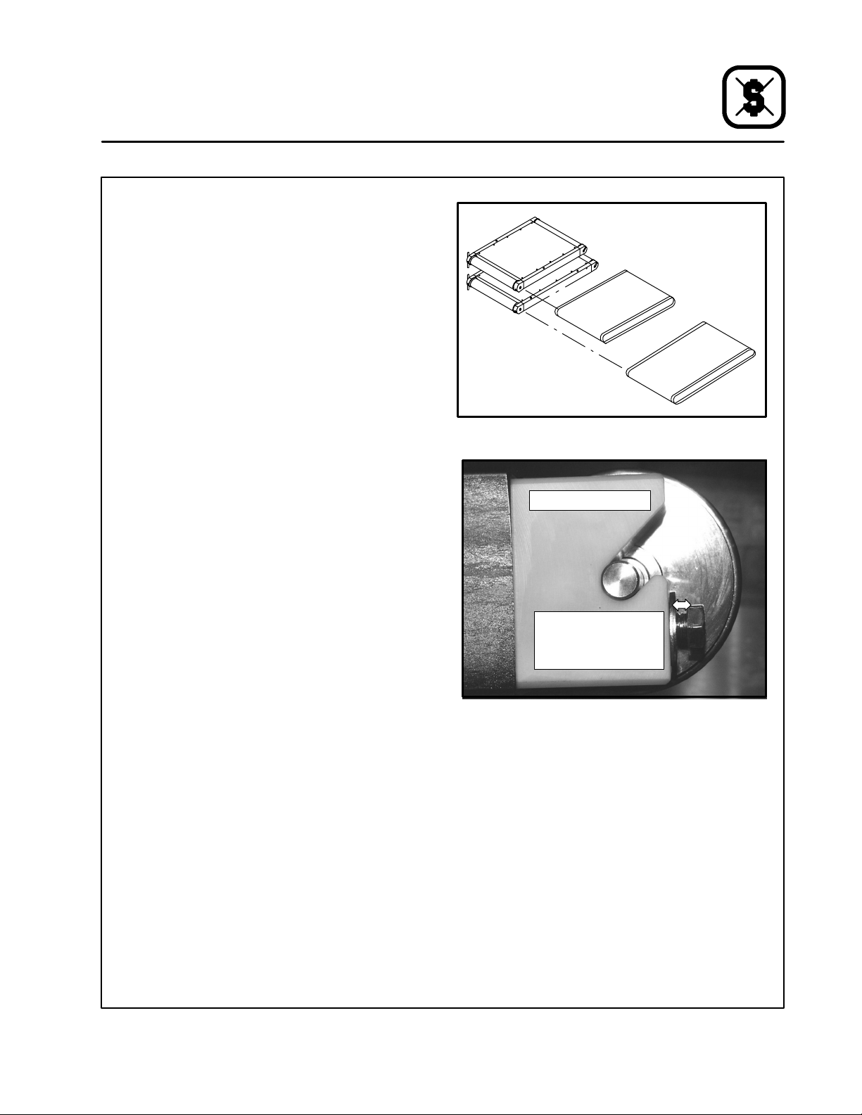
6. Reinstall the belts as follows:
a.) Slide the cooking belts over the rollers on
the platen decks. The longer belt goes on
the lower platen deck. See Figure 12.
b.) After the belts are installed, back the ad-
justing bolts out until there is at least a 1/8”
gap between the bolt head and the plastic
idle roller bearing block. See Figure 13.
The belts will now have tension on them.
c.) Re-check periodically after use to see that
there is still a 1/8” gap, since the belts may
stretch slightly over time.
Maintenance
Cleaning
Upper
Belt
Lower
Belt
Figure 12
End view of idle roller
Approximately 1/8” gap
between bolt head and
idle roller tension block
during normal operation
Figure 13
19
Page 24
Maintenance
Troubleshooting
POSSIBLE CAUSE(S) SUGGESTED REMEDY
SYMPTOM: Food items not moving through the belts
S
Food piles up the the infeed end
S
Food gets stuck betw een the belts
SYMPTOM: Belt not moving
S
The unit has not reached the preheat
temperature
S
Menu key not selected
S
Belt tension not adjusted properly
SYMPTOM: The platen height will not adjust
S
The emergency lift button is engaged.
S
The platen height is not adjusted.
S
The unit is in the program mode.
S
Check the variations in food product t hickness
S
Raise/adjust the height setting
S
Wait for the unit to reach the preheat temperature
S
Select the desired MENU key followed by the
ENTER k ey.
S
Loose or tighten the belt tensioners
S
Release the EMERGENCY button.
S
Hold the LIFT ENABLE to adjust the platen height.
S
Change to Menu mode. Select the desired
MENU k ey followed by the ENTER key.
SYMPTOM: Inconsistent cooking results
S
Inconsistent product thickness
S
Inconsistent final product temperature
SYMPTOM: Lightening under load
S
Product load too heavy
SYMPTOM: Front/middle/back rows bake differently
S
Uneven platen settings
S
Contact or element failure inside a platen
SYMPTOM: Cook time is not correct
S
The control is set for a 60” grill.
*Denotes remedy is a difficult operation and should be performed by qualified personnel only. It is recommended, however, that All
repairs and/or adjustmentsbe done by your local Blodgett service agency and not by the owner/operator. Blodgett cannotassume
responsibility for damage as a result of servicing done by unqualified personnel.
S
Maintain food item thickness
S
Maintain portion control and pre-cooked
temperatures.
S
Stagger food items. The products can be close
but not touching.
S
*
S
*
S
Change the default to 36”. Refer to page 12.
20
 Loading...