

Page 1

TBG36-CM, TBG36-FM AND TBG36-S
ELECTRIC CONVEYOR GRILL
SERVICE AND REPAIR MANUAL
BLODGETT OVEN COMPANY
www.blodgettcorp.com
50 Lakeside Avenue, Box 586, Burlington, Vermont 05402 USA T elephone (800) 331-5842, (802) 860-3700 Fax: (802)864-0183
PN G0173 Rev A (7/01)
E 2001 --- MagiKitch’n Incorporated
Page 2

TABLE OF CONTENTS
1. INTRODUCTION
Unit Description 1 --- 1..................................................................
Specifications 1 --- 2....................................................................
Required Service Tools 1 --- 3............................................................
Electrical Safety 1 --- 3..................................................................
Wiring Diagrams 1 --- 4..................................................................
2. UNIT CONTROLS
Controls Identification 2 --- 1.............................................................
Programming Flow Chart 2---2..........................................................
Operation Flow Chart 2 --- 3.............................................................
Calibration Flow Chart 2 --- 4.............................................................
Controller Removal and Replacement 2---7...............................................
Switch Replacement 2 --- 9..............................................................
3. TEMPERATURE CONTROL
Description 3 --- 1......................................................................
Wiring Diagram 3 --- 2...................................................................
Troubleshooting 3 --- 3..................................................................
Thermostats 3 --- 3..................................................................
Overtemperature Safety Thermostat Circuit 3---4.......................................
Thermocouple Diagnostic Procedure 3---5................................................
Platen Contactor Diagnostic Procedure 3---7..............................................
4. PLATENS
Description 4 --- 1......................................................................
Platen Diagnostic Procedure 4---2.......................................................
Platen Removal and Replacement 4---3..................................................
Platen Removal 4 --- 3...............................................................
Platen Replacement 4 --- 5...........................................................
Platen Alignment 4 --- 6.................................................................
5. POSITION CONTROL
Description 5 --- 1......................................................................
Troubleshooting 5 --- 2..................................................................
Wiring Diagram 5 --- 3...................................................................
Lift Motor 5 --- 4........................................................................
Diagnostic Procedure 5---4..........................................................
Setting Lift Motor Limit Switches 5---4................................................
Removing and Replacing the Lift Motor 5---5..........................................
Linear Potentiometer 5 --- 6..............................................................
i
Page 3

TABLE OF CONTENTS
6. MISCELLANEOUS COMPONENTS
Hourmeter 6 --- 1.......................................................................
Drive Motor 6 --- 2......................................................................
Description 6 --- 2...................................................................
Drive Train Troubleshooting Guide 6--- 3..............................................
Drive Motor Removal and Replacement 6--- 4..........................................
Drive Motor Components Wiring Diagram 6--- 6........................................
Speed Sensor Removal and Replacement 6---7...........................................
Drive Roller and Bearing Block Removal and Replacement 6--- 8............................
Idle Roller T ension Blocks 6-- -10..........................................................
Wipers 6 --- 1 1..........................................................................
7. MAINTENANCE
Service Checks 7 --- 1...................................................................
ii
Page 4

CHAPTER 1
INTRODUCTION
Page 5
BLODGETT CONVEYOR GRILL
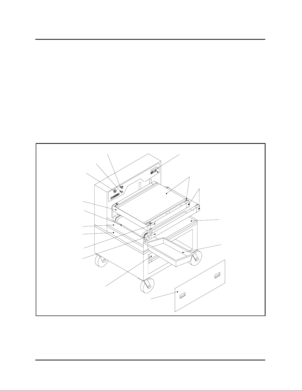
UNIT DESCRIPTION
The Blodgett Conveyor Grill is a microprocessor
controlled conveyorized belt cooking grill built by
Blodgett. The Blodgett Conveyor Grill uses two Teflon coated woven fiberglass belts each encircling
an electrically heated aluminum cooking platen.
Food placed on the lower belt travels over a preheat zone where the product is s lightly thaw ed (in
the case of frozen food) and then between the upper and lower platens where it is cooked on both
sides simultaneously. After cooking, the food falls
into a receiving pan. During the cooking process,
wipers remove excess grease from the belts and
collect it in a grease pa n or bucket in the bottom of
the unit.
Main Power Switch
Lift Enable Button
Emergency Lift Button
Upper Wiper Assembly
The conveyor cooking technique assures consistent, dependable results. By precisely controlling
all the variables --- cooking time, temperature, belt
speed and product contact pressure --- the possibility of improper cooking due to operator error or
inconsistency is greatly minimized. However, it is
still the responsibility of the person(s) operating the
machine to periodicallycheck that the food is properly cooked. The microprocessor controller provides six easy to use programmable menu selections at the push of a button.
Control Panel
Upper&LowerConveyorBelts
Idle Roller
Lower Wiper Assembly
Baffle & Pan Guide
Drain Trough
Upper Platen Deck
Lower Platen Deck
Crumb Tray
Food Receiving Pan
Grease Pan
Door Panel
FIGURE 1
1 --- 1
Page 6

SPECIFICATIONS
INTRODUCTION
DIMENSIONS AND WEIGHT SPECIFICATIONS
TBG36-CM/AA
Counter Model
Width 35.75” (91 cm) 35.75” (91 cm) 43” (109 cm)
Height 31.5” (80 cm) 49.5” (126 cm) 69” (175 cm)
Depth 33.75” (86 cm)* 33.75” (86 cm)* 33.75” (86 cm)*
Weight
Crated
Uncrated
NOTE: * Includes 1.5” ( 3.81 cm) box on rear cover.
TBG36-CM/AA, TBG36-FM and TBG36-S/AA ELECTRICAL SPECIFICATIONS
Hz Vol ts Phase Amps
60/50 208 3 50
60/50 220 3 47
680 lbs (308 kg)
580 lbs (263 kg)
TABLE 1
TBG36-FM/AA
Floor Model
790 lbs (353 kg)
690 lbs (313 kg)
TBG36-S/AA
Stackable Model
1545 lbs (701 kg)
1445 lbs (655 kg)
60/50 240 3 43
60/50 440 3 24
60/50 480 3 22
60/50 380 3 27
60/50 415 3 25
A 3 phase, 50/60 Hz, 3-wire grounded equipment branch circuit, permanently connected in accordance with applicable articles of ANSI/NFPA 70 (NEC code), is required. The stack capacity unit
requires tw o identical circuits.
Provision is made for 1-1/2” trade size conduit for incoming power. UL Listed reducing seals (donut washers) will be required if a smaller size fitting is used. See the Electrical Installation Manual,
P/N 31-12-11343 for details.
Stack capacity (TBG36-S) model requires (2) power feeds, (1) for each cooking section. The stack
capacity design is not currently UL listed in Canada.
TABLE 2
1 --- 2
Page 7

BLODGETT CONVEYOR GRILL
REQUIRED SERVICE TOOLS
In addition to tools normally used when servicing
appliances, you may need the following tools:
These tools can be ordered individually from Blodgett Technical Service (888-992-6624 phone;
802-860-3784 fax) using the Blodgett part numbers shown or a complete kit of these items is available from Blodgett under part number G0235, TBG
Service Tools Kit. In either case, the tools will be
supplied at cost with no mark-up on a one-time ba-
QTY
1 Digital Multimeter Amprobe AM-1260 or similar;
1 Clamp-on ammeter Amprobe model RS-3 or similar;
1 24 VDC lift motor power supply (optional) Blodgett P/N G0239
1 Molex Mini fit crimping tool Molex 11-01-0197-P;
1 Molex Mini fit pin extraction tool Molex 11-03-0044;
DESCRIPTION P/N
sis. Replacement tools will be billed at the usual
dealer/agency price.
A Service Parts Replacement Kit (part number
G0236) is also available. This kit contains pa rt s that
normally require replacement and a few critical
components. This kit will be billed at full price with
replacements made for warranty usage when accompanied by complete documentation.
Blodgett P/N G0237
Blodgett P/N G0238
Blodgett P/N G0240
Blodgett P/N G0241
20 Molex Mini fit Jr. female pins Molex 39-00-0039;
Blodgett P/N G0242
1 Anti-seize compound, food grade, can McMaster 1404K11 or similar;
Blodgett P/N G0243
TABLE 3
ELECTRICAL SAFETY
De-energizing the unit
For servicing purposes throughout this manual,
two distinct operations are referred to frequently
and their meaning must be understood clearly for
your safety. One is the use of the Main Power
Switch and the other is “disconnect supplypower”.
The main power switch turns the Blodgett Conveyor Grill on and off for all user purposes. When working inside the machine, however, the main power
feed wires and over-temperature protection ther-
mostat wiring are very much alive and remain so
whetherthemainpowerswitchisonoroff.
To de-energize the machine completely, the
supply power must be disconnected at the circuit breaker or (fused) disconnect switch labeled for this unit.
NOTE: Stack capacity units have separate power
supplies. Be sure the power has been
turned off for the appropriate unit.
1 --- 3
Page 8
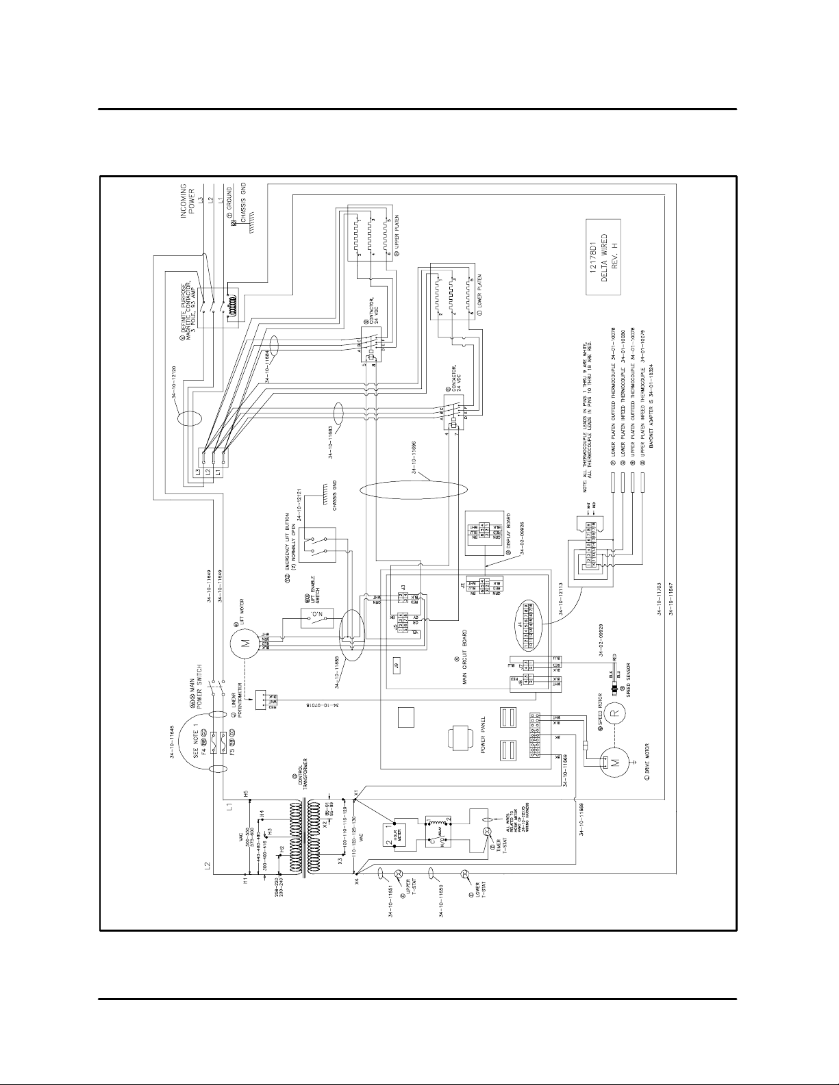
WIRING DIAGRAMS
INTRODUCTION
FIGURE 2
1 --- 4
Page 9
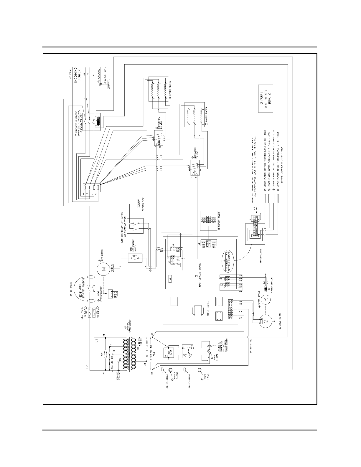
BLODGETT CONVEYOR GRILL
FIGURE 3
1 --- 5
Page 10

CHAPTER 2
UNIT CONTROLS
Page 11
BLODGETT CONVEYOR GRILL
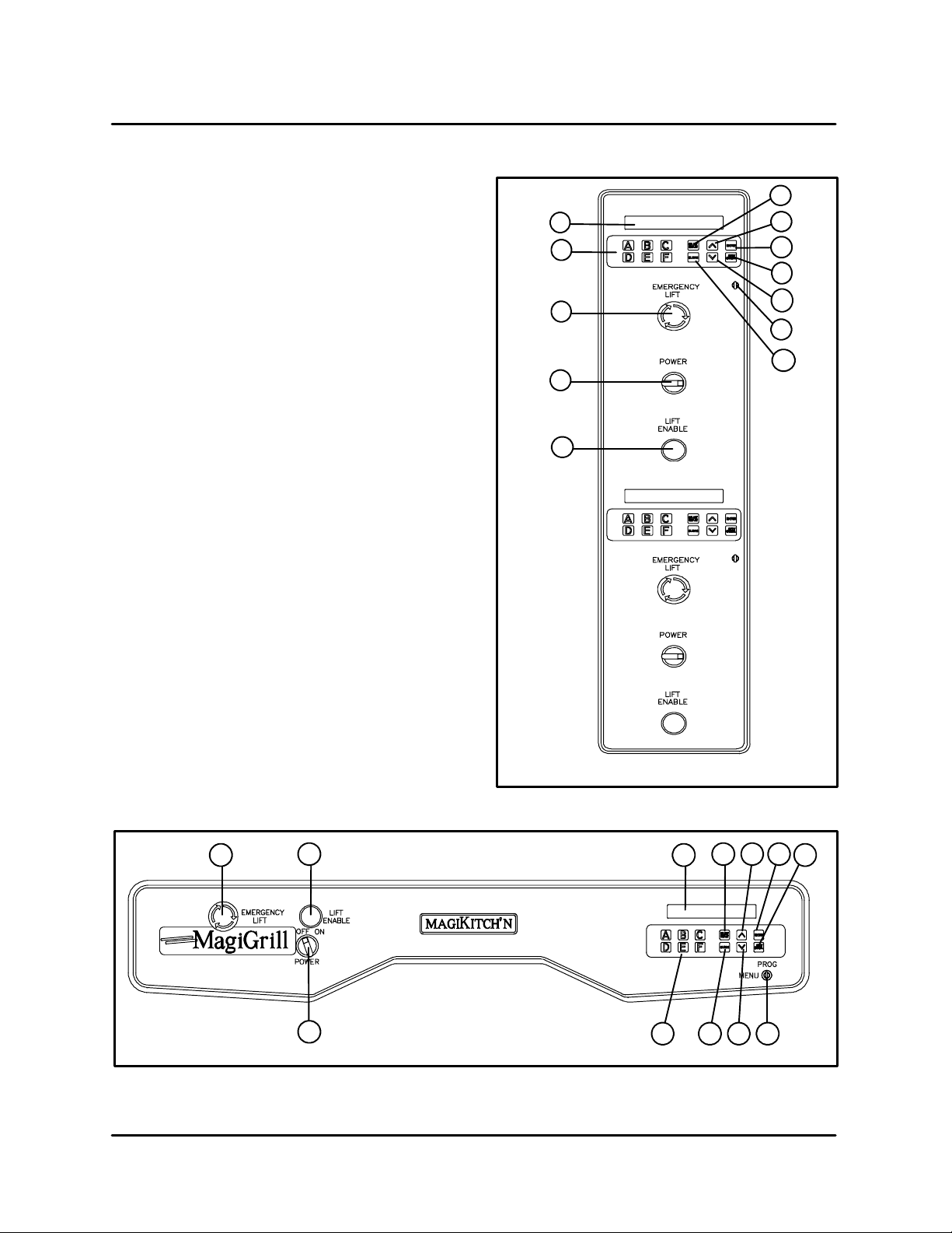
CONTROLS IDENTIFICATION
1. SELECT/DISPLAY --- used to select the display information.
2. UP and DOWN ARROW --- u s e d i n p r o g r a m ming to increase/decrease selection choices.
3. ENTER --- used to enter a menu selection into
the current program.
4. OFF/CANCEL --- cancels the current menu so
another may be entered.
5. KEYSWITCH --- requires a key to change from
MENU mode to PROGRAM mode.
6. CLEAN --- raises the upper platen for thorough
cleaning.
7. MENU buttons --- used in the MENU mode to
load programming for products A through F.
Used in PROGRAM mode to select menu designations and product descriptions.
8. DISPLAY --- displays the menu and program
mode information selected.
9. EMERGENCY LIFT --- immediately raises the
upper platen to the clean position. Push and
turn to reset/release button.
11
10
1
8
7
9
2
3
4
2
5
6
10. LIFT ENABLE --- a safety feature requiring the
operator to hold the button in while moving the
platen to a cooking position after a programming adjustment or menu change.
11. MAIN POWER SWITCH --- An ON-OFF rotary
switch for emergency or convenience use
which controls all electrical power inside the
unit. When power is on, the display lights up.
10
11
TBG36-CM and TBG36-FM Control
FIGURE 2
TBG36-S Control
FIGURE 1
89
7
1 2 3
526
4
2 --- 1
Page 12
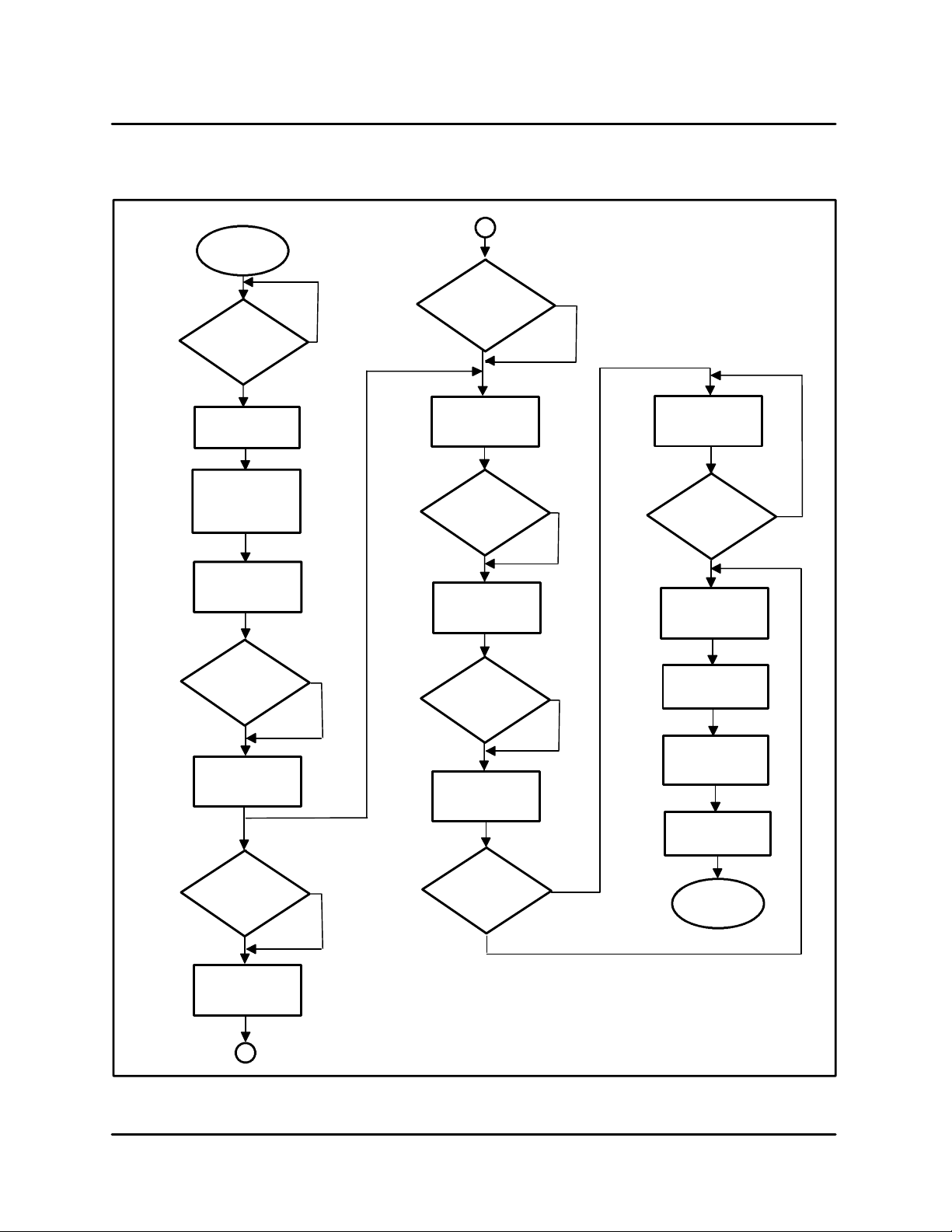
PROGRAMMING FLOW CHART
Power Switch
ON
Turn
KEYSWITCH
to vertical
position
Display reads
PROG?A
YES
NO
Belt Speed
A
Press
ARROW KEYS
to set
PH = BH
UP
Press ENTER
display reads
T=XX.XX
UNIT CONTROLS
DOWN
CHANGE SPELLING
Select letter
with
ARROW KEYS
L E T T E R K E Y A --- F
Top H e a ter
Press ENTER
display reads
ARROW KEYS
to set temp
Bottom Heater
Press ENTER
display reads
TBG60
ARROW KEYS
to set temp
Press the
youwishto
program
TH = XXX
Press
UP
BH = XXX
Press
DOWN
TBG36
DOWN
ARROW KEYS
to set time
Height Between
Platens
Change
Food Product
Descriptions
Press ENTER
display reads
H=XX.XX
ARROW KEYS
to set height
Press ENTER
display reads
FOOD PRODUCT
Press
Press
Change
product
spelling?
UP
UP
DOWN
DOWN
YES
CONTINUE
SPELLING
Press
ENTER to lock
in letter
DONE
Press
SELECT DISPLAY
Display reads
SAVE A>F
Press ENTER
display reads
SAVING
Display reads
PROG?A
Finished
programming
Preheater
Press ENTER
display reads
PH = XXX
A
UP
NO
NOTES:
_
All temperature setting must be less than or equal to 450
Platen height (H = X.XXX) must be less than or equal to 1.900” and greater than or
equal to 0.100”
Belt speed (T = X.XXX) must be less than or equal to 10 minutes and greater than or
equal to 30 seconds.
F
FIGURE 3
2 --- 2
Page 13
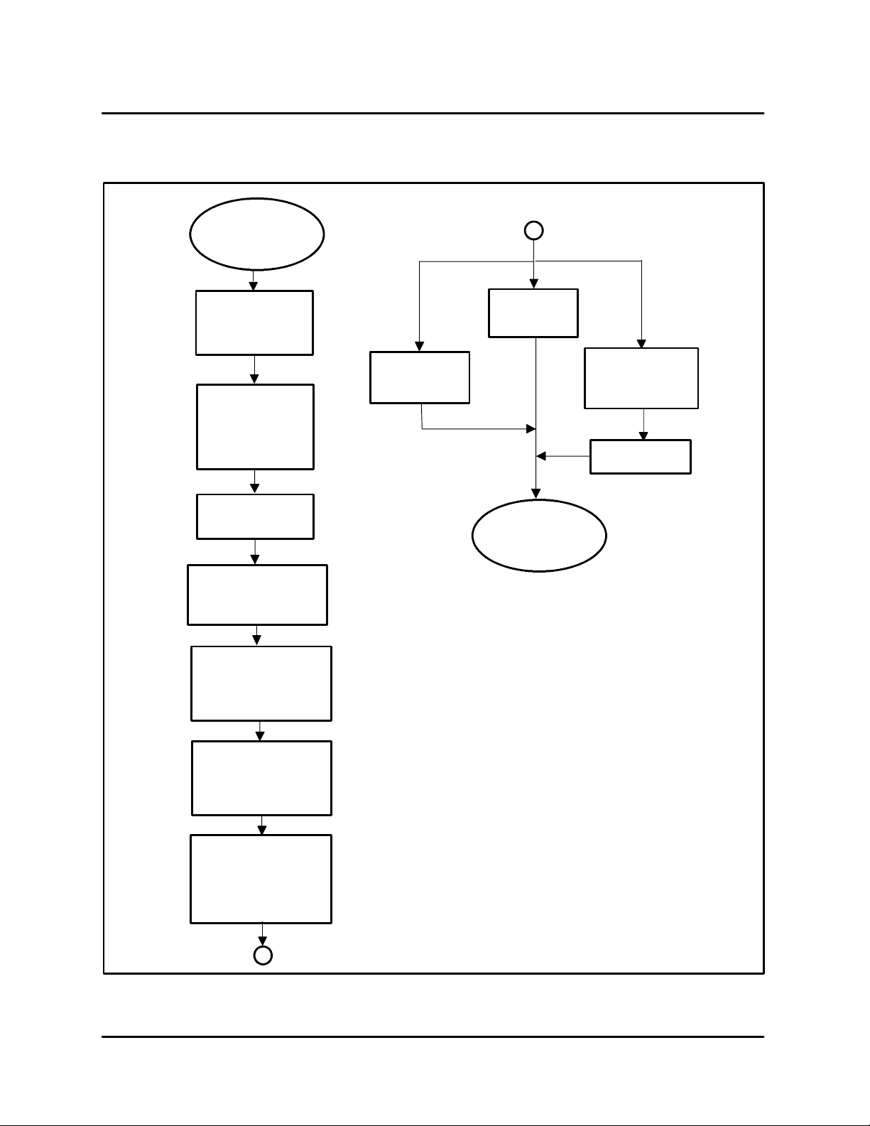
BLODGETT CONVEYOR GRILL
OPERATION FLOW CHART
Turn on
MAIN POWER
SWITCH
(turn knob to right)
A
Release
EMERGENCY LIFT
if set
(turn knob to right)
Turn
KEYSWITCH
to Menu
(horizontal position
display reads
MENU?A
Press (1) desired
menus selection
button A ---F
Press and hold
ENTER and LIFT ENABLE
buttons at the same time
oven beeps
Release ENTER
hold LIFT ENABLE
until upper platen lowers
to cooking height and
stops
Push Red
EMERGENCY LIFT
button
Cooking cycle
complete
T=00:00
Push OFF/CANCEL
display reads
remaining time
T=XX:XX
Push
OFF/CANCEL
Finish
select new program
Display reads
STANDBY
platens preheat and
counts down from 15 min.
T=XX:XX
Roller and belts start
moving
Blodgett Conveyor Grill
ready to cook
(display scrolls cooking
description)
A
FIGURE 4
2 --- 3
Page 14
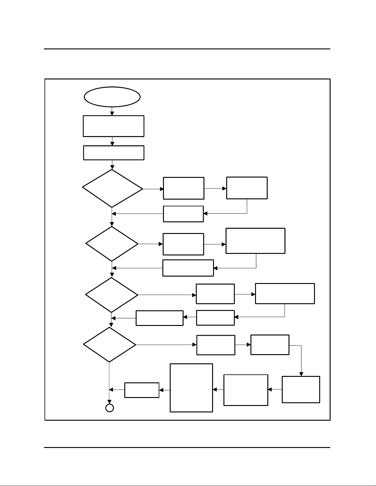
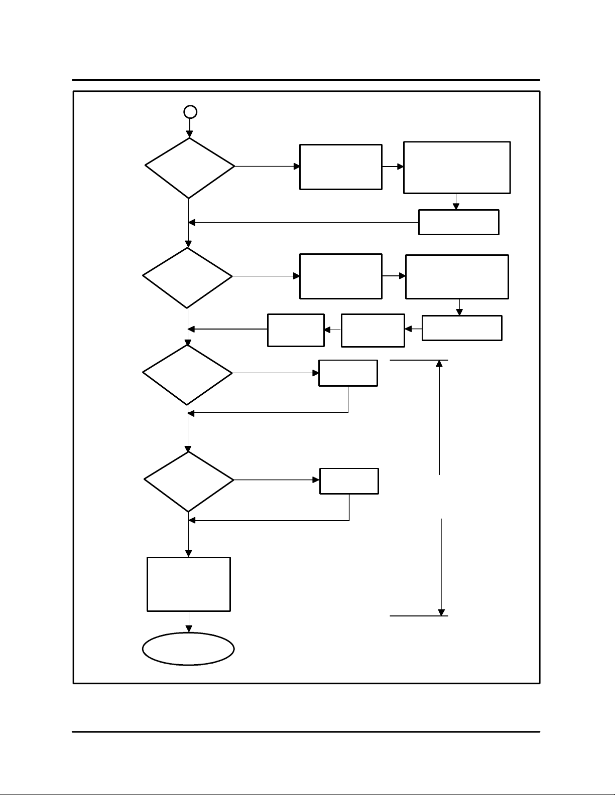
CALIBRATION FLOW CHART
UNIT CONTROLS
START/POWER
Turn KEY to program
(vertical position)
Press SELECT DISPLAY
Display reads PSWD?::
Unlocks Display
Press ENTER then A
Display reads
0:SELECT MODEL
Press ARROW key
to continue
programming
display reads
1:LIFT CAL
Press ARROW key
to continue
programming
2:CJ CAL
switch on
Press
A button
Display
reads
Change linear pot
calibration
Calibrate thermocouple
cold junctions
THE PASSWORD MODE ALLOWS ACCESS TO THE PROGRAMMING LOGIC AREA OF THE MICROPROCESSOR CONTROLLER.
DO NOT ATTEMPT TO ALTER A SETTING WITHOUT A COMPLETE
UNDERSTANDING OF THE CONTROLLER AND ITS PROGRAMMING AND A DIRECT CONSULTATION/APPROVAL FROM BLODGETT TECHNICAL SERVICE, 888-992-6624. THIS AREA IS USED
FOR INITIAL CALIBRATION, MENU DEVELOPMENT, TESTING
COMPONENT FUNCTION AND ADJUSTING PROGRAM VARIABLES BY A SERVICE TECHNICIAN. THIS AREA SHOULD NOT BE
ACCESSED BY THE USER.
Press ENTER
display reads
TBG36 or TBG60
When finished
Press ENTER
Press ENTER
display reads
H=X.XXX
When finished
Press
OFF/CANCEL
Press ENTER
display reads
CJ=XX
Press ARROW
keys to
select
Press ARROW keys
and LIFT ENABLE to
set height. Calibrate with
known dimension
Press ARROW keys
to adjust. Use external
meter for calibration
Press ARROW key
to continue
programming
Display reads
3:TEMP CAL
Press ARROW key
to continue
programming
A
When finished press
OFF/CANCEL
Calibrate 3 platens
to external reference
Press
OFF/CANCEL
Press ENTER
Press ENTER
display reads
SET = 400
Set
TH = SET
BH = SET
PH = SET
with ARROW keys
Set each
temperature by
pressing ENTER
FIGURE 5
2 --- 4
to save
Press ARROW
keys to set
temperature
Scroll display with
SELECT DISPLAY
compare
temperature with
external meter
Press ENTER
3 platens heat
to temperature
and stabilize
Page 15
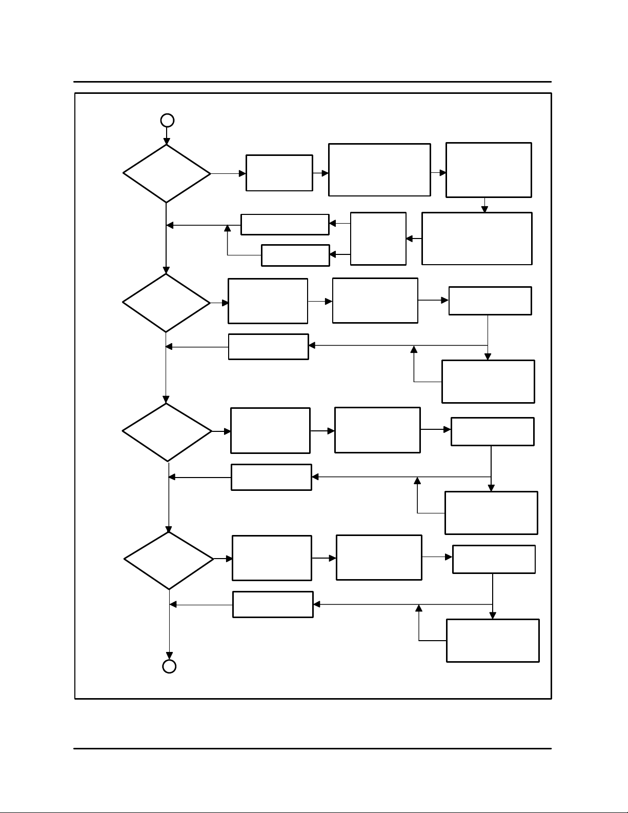
BLODGETT CONVEYOR GRILL
A
Change all cooking
menu parameters while
operating
Display reads
4:TEST COOK
Press ENTER
then a menu key
A --- F
Press ENTER and
LIFT ENABLE
release ENTER
(hold LIFT ENABLE
until platen stops moving)
Display reads
T = XX:XX
(counts down until up
to temperature)
belts start moving
Press ARROW key
to continue
programming
Display reads
5:SET TOPHEAT
Press ARROW key
to continue
programming
Display reads
6:SET BOT HEAT
Press ARROW key
to continue
programming
Display reads
7:SET PREHEAT
Change top
platen temperature
(actual platen temp)
Press OFF/CANCEL
Change bottom
platen temperature
(actual platen temp)
Press OFF/CANCEL
Change preheat
platen temperature
(actual platen temp)
Default to old setting
Press OFF/CANCEL
Save changes
press ENTER
Press ENTER
display reads
T = XXX
twice to exit
Press ENTER
display reads
T = XXX
twice to exit
Press ENTER
display reads
T = XXX
When
done
press
OFF/CANCEL
Press OFF/CANCEL
display reads
TH XXX
(current platen temp)
Press OFF/CANCEL
display reads
BH XXX
(current platen temp)
Press OFF/CANCEL
display reads
PH XXX
(current platen temp)
Press SELECT/DISPLAY
Use ARROW keys to select
parameter to change
TH BH PH T H
(change to desired setting)
Press ARROW keys
to adjust temperature
Press ENTER
display reads
T = XXX
(shows platens temp)
Press ARROW keys
to adjust temperature
Press ENTER
display reads
T = XXX
(shows platens temp)
Press ARROW keys
to adjust temperature
Press ARROW key
to continue
programming
Press OFF/CANCEL
twice to exit
Press ENTER
display reads
T = XXX
(shows platens temp)
B
FIGURE 6
2 --- 5
Page 16
Display reads
Press ARROW key
to continue
programming
Display reads
SET HEIGHT
Press ARROW key
to continue
programming
B
8:SET TIME
Discontinues all
password setting
8through10
FOR TECHNICIAN ONLY
Shows main control board is
picking up magnetic speed
control output
Obsolete Function
LIFT CAL does the
same function
Press
OFF/CANCEL
twice to exit
Press ENTER
display reads
T = X:XX
(shows a time value)
Press ENTER
display reads
P=X.XXX
(current position)
When finished
display reads
P = X.XXX
UNIT CONTROLS
Press ENTER
display reads
S=XXXXX
(shows fluctuating number)
pick up is working “OK”
Press OFF/CANCEL
twice to exit
Press OFF/CANCEL
display reads
P = X.XXX
(adjust to desired height)
Press ENTER
platen will adjust
Display reads
10:STOP ALL
Press ARROW key
to continue
programming
Display reads
11:DEFAULT MENU
Press ARROW key
to continue
programming
Scroll through the
following
12:EE WORD
13:EE BYTE
14:SET CHECKSUM
FINISHED
Only to change all
menus to preset variables
RESTRICTED
DO NOT ACCESS
FOR ENGINEERING
ONLY
Press ENTER
to change
Press ENTER
to change
Press OFF/
CANCEL
to exit
FIGURE 7
2 --- 6
Page 17
BLODGETT CONVEYOR GRILL
CONTROLLER REMOVAL AND REPLACEMENT
If repeated nuisance blowing of fuses persists, the
current rating of any of the fuses may be increased
to 5 amperes. The following are symptoms for a
blown fuse:
D
Definite Purpose Contactor pulls in but the display
remains blank. One of the following fuses has
blown. Fuse 1 (3A Slow-blo 24VDC), Fuse 2 (3A
Slow-blo 120VAC) or Fuse 4 (3A Slow-blo 24VAC)
D
Controller works but there is no belt drive motor operation. Fuse 3 (3A Slow-blo Drive Motor)
blown.
2
3
1
4
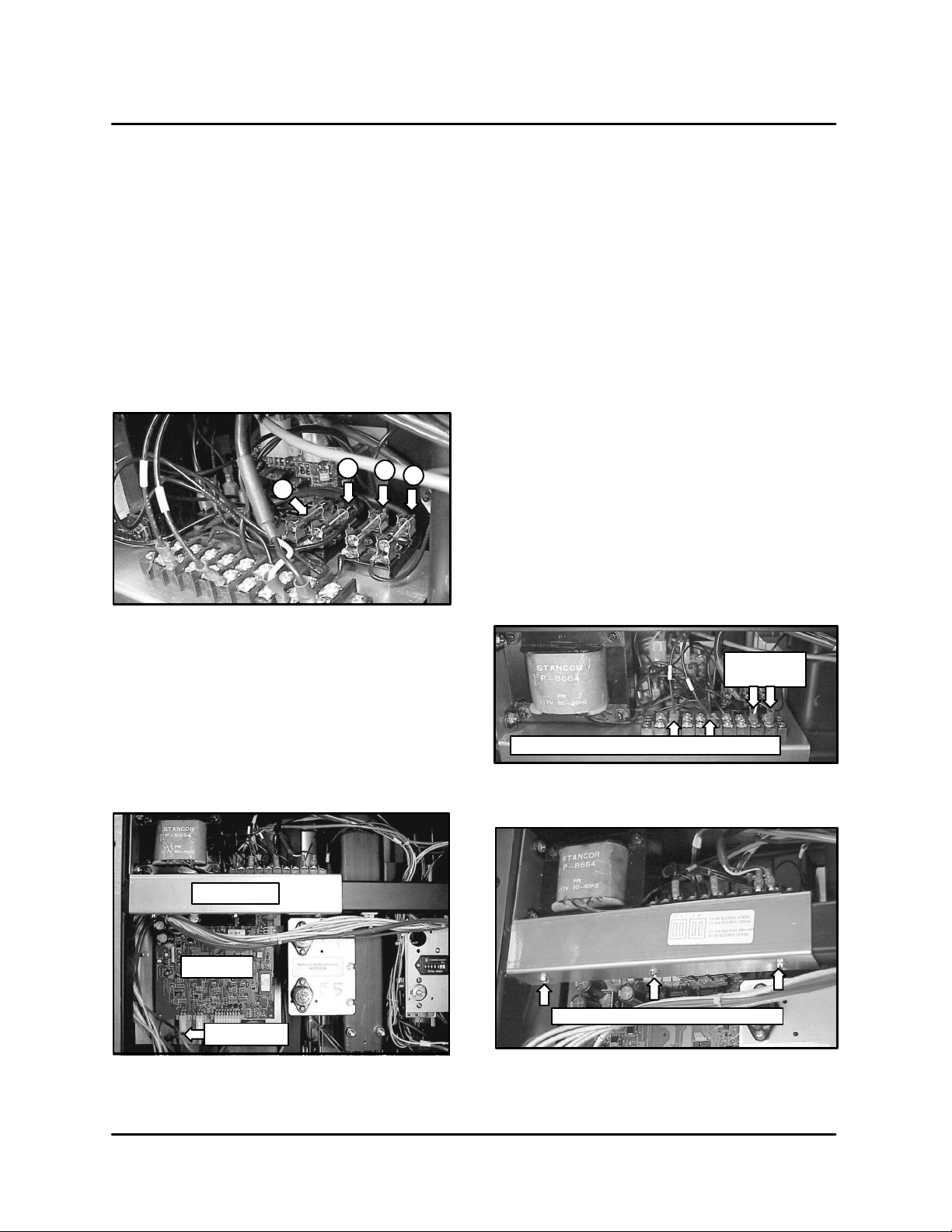
FIGURE 8
1. Remove the power supply as follows:
A.) Remove the three screw s securing t he
power supply mounting bracket to the
frame crossmember.
B.) Pull the power supply assembly/bracket
out of the unit about an inch to access the
screws on the terminal strip.
C.) Remove the two w ires from the drive motor
on the power supply terminal strip noting
which wire goes to which point on the terminal strip. If these are connected incorrectly the drive motor will run backwards.
D.) Remove the two wires supplying 120 VAC
from the 375 VA isolation transformer (located on the opposite side of the unit) to
the power supply terminal strip from the
terminal strip.
E.) Disconnect the power supply cable Molex
connector from plug J-9 on the main
board. Remove the power supply from the
unitandsetitaside.
The controller must be replaced as a set with the
following components:
D
Main board
D
Power supply board
D
Display
D
Display cable
Power Supply
Main Board
Display Cable
FIGURE 9
Drive Motor
Supply Wires
Wires from power transformer to power supply
FIGURE 10
Power supply bracket mounting screws
FIGURE 11
2 --- 7
Page 18
UNIT CONTROLS
2. Remove the main board as follows:
A.) Remove all other Molex connectors from
the main board. Note which connector
goes to which pin location on the board.
Be especially careful when removing/reconnecting the two 4 pin connectors from
J-7 and J-8 which are identical in appearance and are located a djacent to each other. If these are inadvertently switched the
display will show all segments lit when the
unit is energized. No damage to the board
will result, simply cycle the power off and
then switch the connectors to the correct
plugs before re-energizing.
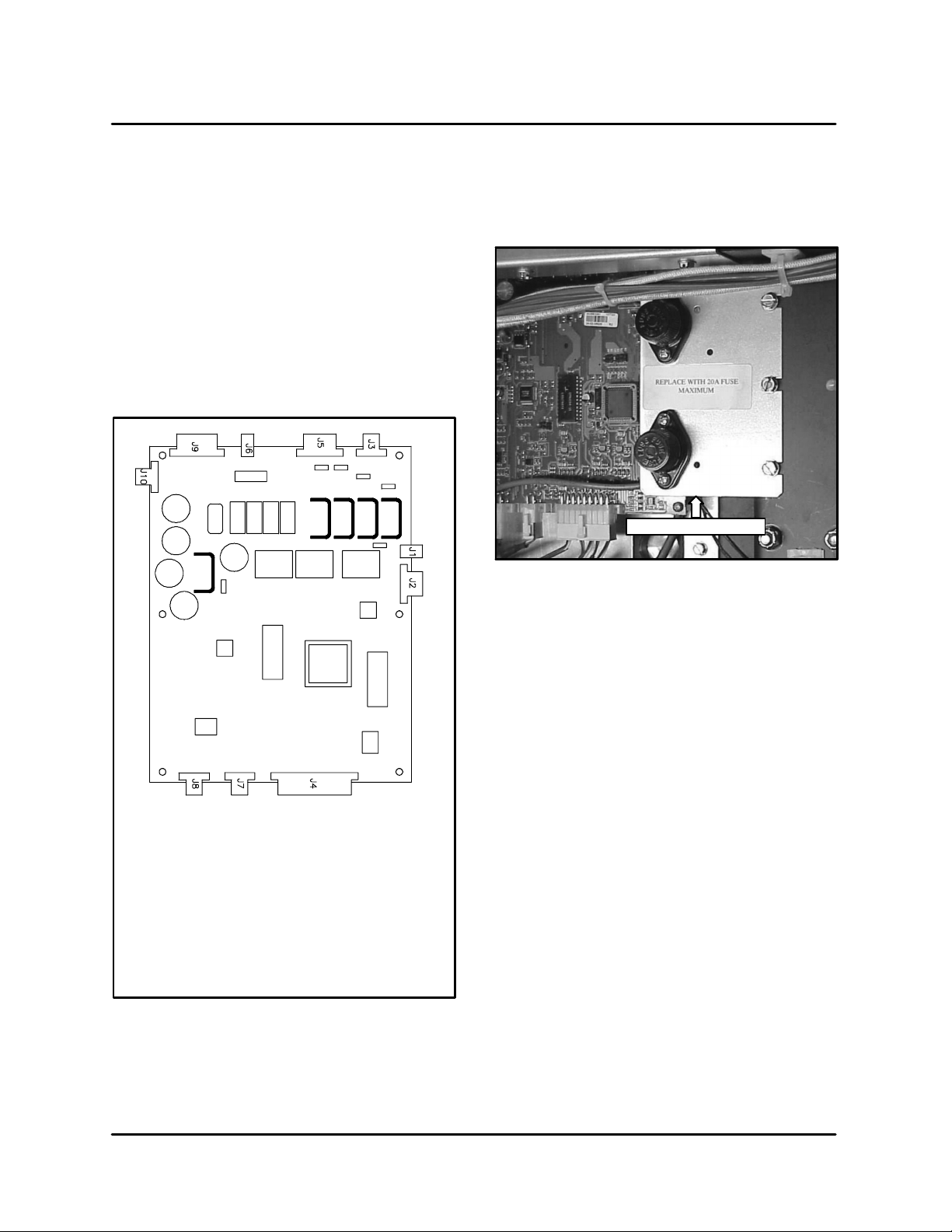
B.) Remove the screws securing the fuse
mounting bracket and move this out of the
way to allow the main board mounting
panel and main board to be removed as an
assembly.
Fuse mounting bracket
FIGURE 13
Plug Designations
J1 Not used
J2 Display
J3 Lift Motor
J4 Thermocouples
J5 Heating Contactors
J6 Not Used
J7 Speed Sensor
J8 Linear Potentiometer
J9 Power Supply
J10 Not Used
FIGURE 12
C.) Remove the main board by loosening, but
not removing, the three screws securing it
to the upright frame member. Remove the
screw securing it to the horizontal frame
member.
3. Remove the display board a s follows:
A.) Remove the (5) small nuts securing the
display to its stand-offs.
B.) Remove the display board.
4. Installation of the display, power supply panel,
and main board is opposite of removal. A linear
potentiometer calibration must be run following replacement of the control board. See
p a ge 5 --- 6 o f t h e P OS I T I O N C O NT R O L s e ct i o n
of this manual.
2 --- 8
Page 19

BLODGETT CONVEYOR GRILL
SWITCH REPLACEMENT
The following procedure describes how to replace
the Emergency Lift, Power and Lift Enable switches.
1. Remove the drive motor to gain access to the
switches.
2. TheLIFTENABLEandPOWERswitcheshave
similar constructions. Replace as follows:
Lift Enable Actuator Components
Normally Open
Contact Block
(snaps into back
of mounting bracket)
Contact Block
Mounting Bracket
A.) Remove the wiring from the back of the
switches.
B.) Turn the black plastic tab securing the
switch to its actuator. If the actuator needs
to be removed, remove the plastic nut from
the barrel of the actuator and pull the actuator out through the front of the unit.
Plastic Nut
(secures actuator to
sheetmetal panel)
Actuator
Power Switch Components
Mounting bracket with
tab turned to unlock
bracket from actuator
(note that four notches
are open)
Mounting bracket with
tab turned to lock
bracket to actuator
FIGURE 14
2 --- 9
Complete switch/actuator
assembly
Page 20

Emergency Switch Components
UNIT CONTROLS
Contact Block
Assembly
Mounting Block
Complete Emergency Switch Assembly
(Note tips of screws protruding out of mounting block.
These screws must be tightened against the sheetme-
tal to secure the actuator in place before assembling
the contact block assembly to the mounting block.)
Actuator
FIGURE 15
2 --- 1 0
Page 21

BLODGETT CONVEYOR GRILL
This page intentionally left blank.
2 --- 1 1
Page 22

CHAPTER 3
TEMPERATURE CONTROL
Page 23

BLODGETT CONVEYOR GRILL
DESCRIPTION
The temperature control circuitry for the Blodgett
Conveyor Oven employs two (2) J -type thermocouples located at the infeed and outfeed ends of
each heating platen. The thermocouple outputs
are fed into the control board through the Molex
connector on J-4. When the platen t emperature
drops below the programmed set point, a controller relay energizes a three-phase power contactor.
The contactor energizes three heating elements in
the platen until the platen temperature passes a
With back cover
differential set point and reaches the correct cooking temperature. The controller de-energizes the
contactor, cutting power to the heating elements.
As the platen loses heat in cooking, this cycle repeats itself.
Over-temperature protection is provided by thermostats which are normally closed and designed
to open at 583˚F. These are wired in series with t he
coil of the definite purpose contactor which controls power to the entire unit.
With back cover removed
FIGURE 1
3 --- 1
Page 24

WIRING DIAGRAM
TEMPERATURE CONTROL
FIGURE 2
3 --- 2
Page 25

BLODGETT CONVEYOR GRILL
TROUBLESHOOTING
A problem with uneven cooking or undercooking
of food on the top and/or bottom surface may be
the result of a temperature control malfunction. It
is advisable to use the Cooking Troubleshooting
Guide in isolating the cause of the problem. Possible causes for improper cooking operation that
could be the fault of the temperature control include:
D
Broken thermocouple wiring.
D
Looseorbrokenwiresfromtheplatens.
D
Platen contactor failure.
D
Platen heating element failure.
Pillow Block
Upper Thermostat
THERMOSTATS
Theplatensareprotectedfromoverheatingby
bulb sensor type thermostats. The bulbs sensors
are located w ithin thermowells cast into the platens. These thermowells are located in the center of
the (6) element sheaths exiting the side of the platen castings.
Thermostat Sensor Capillary
(thin bare copper tube)
Linear Shaft
Mounting Plate
FIGURE 4
Lower Thermostat
FIGURE 5
FIGURE 3
3 --- 3
Page 26

TEMPERATURE CONTROL
OVERTEMPERATURE SAFETY THERMOSTAT CIRCUIT
A problem with the overtemperature safety circuit
is indicated when a hot grill shuts off for no apparent reason. There is a noticeable thunk sound from
the back of the unit, indicating that the definite purpose contactor has de-energized and dropped out
all power to the platens. No display warning is given. Power to the platens shuts down completely
until the temperature of the problem platen has
cooled enough to reset the thermostat, at which
time the unit restarts.
Overtemperature sa fety thermostat problem
If an overtemperature safety thermostat fails by actuating at too low a temperature (one within the
normal cooking temperature range of up t o 450˚F)
the grill will still shut off, even though there is no
temperature problem. If this condition occurs:
1. Disconnect supply power at the branch circuit
breakerandremovethebackcoverwhilethe
unit is still hot. Be certain the wiring is de-energized by testing with a voltmeter.
2. Remove one of the w ires from the thermostat
and measure across the wiring terminals of
each of the overtemperature thermostats with
an ohmmeter to find the open device. This
must be accomplished before the thermostat
cools down and resets itself. The open switch
is the thermostat that has actuated prematurely, the others will read closed (zero ohms).
3. When the platen cools down, the actuated
switch will close again automatically.
4. The safety thermostat is either out of adjustment or defective and in need of replacement.
Overtemperature safety circuit problem
If a grill does not start at all, and all the obvious requirements are met (cord plugged in, power available, etc.) then the O/T safety circuit may be suspect. To test with the unit at room temperature:
1. Open the supply power breaker and check for
continuity through the thermostats, definite
purpose contactor coil, and wiring.
2. If there is an open circuit, label and isolate the
wiring, connections, and components. Check
for device continuity with the wires removed.
3. Repair or replace defective wiring and/or components as necessary.
Overtemperature protection thermostat with shaft in
proper position (normally closed, continuity between
wires)
Note 12:00 position of microswitch actuating pawl.
Note that microswitch is closed. Microswitch is not part
of circuit.
Overtemperature protection thermostat with shaft in
wrong position (open circuit between wires).
Note 3:00 position of microswitch actuating pawl.
Note that microswitchis open. Microswitch is not part of
circuit.
FIGURE 6
3 --- 4
Page 27

BLODGETT CONVEYOR GRILL
THERMOCOUPLE DIAGNOSTIC PROCEDURE
1. Visually inspect for any broken wires. Check at
control board connector J-4 for any bare wires
touching one another or ground.
2. To test suspect thermocouples at room temperature, unplug the Molex connector from J-4
on the controller board and measure the thermocouple’s output (temperature) using the
digital thermometer and a pair of test leads (Jtype if available) from the connector pins.
3. Follow the Molex diagram and compare their
readings against the room ambient. If outputs
are not within +/ --- 10%, replace the thermocouple. The 18 pin Molex plug must be disconnected from the control board to take readings
from individual thermocouples s ince the infeed
and outfeed thermocouples are averaged together on the control board and must be separated for testing.
A small section of thermocouple wire must be
connected to pins 8 a nd 17.
NOTE: These pins correspond to a separate
preheat platen used on a larger version
of this appliance. While they are not
used on this unit, a thermocouple input
must be provided to these two locations or the resulting open channel will
cause a problem with the control.
A digital multimeter (preferably with a diode test feature) is required. Remove the 18-pin Molex connector from the controller before proceeding. See the illustrations below and complete these steps in order
until the problem is identified and corrected.
Plug Designations
J1 Not used
J2 Display
J3 Lift Motor
J4 Thermocouples
J5 Heating Contactors
J6 Not Used
J7 Speed Sensor
J8 Linear Potentiometer
J9 Power Supply
J10 Not Used
FIGURE 7
NOTE: All thermocouple leads in Pins 1 thru 9 are white
All Thermocouple l eads in Pins 10 thru 18 are red.
Bottom Outfeed Thermocouple
Bottom Infeed Thermocouple
Top Outfeed Thermocouple
Top Infeed Thermocouple
FIGURE 8
3 --- 5
Page 28

TEMPERATURE CONTROL
Ref. Figure Red + Probe Black -- Probe Result
FIGURE 9
(Rule out
thermocouple
wiring shorted to
ground)
FIGURE 10
(Test T/C
junction integrity)
NOTE: It is easier to connect meter leads to Molex sockets if a spare Molex pin or an opened paper clip
is temporarily placed in the plug socket under test and the meter lead connected to the pin or clip.
Each socket on the
white Molex plug,
one at a time*.
Molex pin for one
thermocouple w h ite
wire.
See FIGURE 8*.
Ground lug on unit*. Should read open (no continuity, no
beep). If it does not, note the socket
number and identify the faulty thermocouple from the diagram above. Trace
theleadwireandlookforplaceswhere
bare thermocouple wire may be touching grounded metal. Remove the thermocouple from the platen well tube and
check for bare conductors.
Molex pin for one
thermocouple red
wire.
See FIGURE 8*.
TABLE 1
Each thermocouple should have continuity from white to red. If not, the thermocouple is open and needs to be replaced.
FIGURE 9 FIGURE 10
3 --- 6
Page 29

BLODGETT CONVEYOR GRILL
PLATEN CONTACTOR DIAGNOSTIC PROCEDURE
1. Disconnect supply power by opening the circuit break er to de-energize the unit.
2. Remove back cover and label all t h e wires connected to the suspect heating contactor.
3. Disconnect all the wires on the contactor and
measure the coil resistance. The value should
be between 82 and 110 W; if not, the coil is
faulty and the contactor must be replaced.
Control
Board
Controller
Power
Supply
Primary
Transf ormer
Fuses
Linear
Potentiometer
4. Check that there is an open circuit (infinite resistance) across each of the pole pairs of the
contactor.
5. Connect a separate 24VDC power supply to
energize the contactor coil and recheck the
pole resistances again. When energized, they
should show almost zero resistance. If not, the
contactor is defective and must be replaced.
Hour
Meter
Top Pla t en
Safety
Thermostat
Drive
Roller
Sprockets
Drive
Chain
Power
Distribution
Block
Definite
Purpose
Contactor
Ground Lug Lift
Motor
Heat
Contactors
FIGURE 11
3 --- 7
Bottom
Platen
Safety
Thermostat
Main Power
Transf ormer
Page 30

CHAPTER 4
PLATENS
Page 31

BLODGETT CONVEYOR GRILL
DESCRIPTION
Theupperandlowerplatensaremadefromcast
aluminum with an electroless nickel coating. Three
incoloy sheathed elements are cast into each platen running lengthwise. A thermocouple is located
on the infeed and outfeed end of each platen to
provide accurate temperature monitoring. Sheet-
metal filler strips and a cover surround the platen
to protect the thermocouples and to improve
cleanability. The platens are aligned to each other
by means of adjusting bolts in the platen frame assemblies. No maintenance other than routine
cleaning is required.
FIGURE 1
4 --- 1
Page 32

PLATEN DIAGNOSTIC PROCEDURE
WARNING!!
Be careful! You will be working near LIVE
ACpowerof208voltsorgreater!
Stack capacity models have two services.
Check that the correct circuit has been
turned off! When working on a de-energized stack capacity unit, half the unit may
still be live (energized)! DO NOT accidentally reach into the wrong section! For
your safety, replace the back cover on an
energized unit that is not being serviced.
In normal operation, one side of each
heating element is alwa ys energized relative to ground whenever the supply power
breaker is on, regardless of the main pow er switch position!
1. Re-energize the unit and run it from a cold start
in Menu A. Set the temperatures above 375_F.
2. While the platens are heating, measure the
current draw through each branch conductor,
feeding power into the unit using a clamp-on
tester. Compare measurements to TABLE 1. If
the values do not agree, measure the draw of
the individual heating elements in the platens
at the contactors. Compare against TABLE 1.
3. If all three feed wires read about half normal
current, an entire platen is not working. If two
of three feed wires read a ppreciably lower than
normal, one or two heating elements in a platen may be defective. You can check the current draws of the individual platen elements by
PLATENS
locating and measuring the current draw on
the individual supply wires to each of the platens at their contactor. Be careful, you will be
working with a live, hi-voltage circuit. Refer to
TABLE1forcorrectlinedrawsfortheplaten.
4. To isolate the suspect heating element:
A.) Open the power disconnect to de-ener-
gizetheunitandletitcooldown.
B.) Label then disconnect the three high tem-
perature wires (fiber cloth covered) from the
top of the heating contactor of the platen.
C.) Label then disconnect all the high temper-
ature wires from the main power terminal
block. Separate wires to keep them from
touching each other.
D.) Isolate each of the three elements in the
platen and measure the cold resistance
through them. Refer to TABLE 1 for the
correct resistance value for the voltage
andplatenonwhichyouareworking.
E.) Checktheresistanceofeachwireleadto
ground; they should read infinite resistance (open circuit). If one or more elements fail to meet these criteria, the heating platen must be replaced. If the heating
elements are good, the problem lies in the
wiring associated with heating.
F.) Be careful removing or re-connecting wir-
ing. DO NOT twist (break) the terminals off.
Be sure that all connections are secure.
TBG36 CURRENT DRAWS
208 VAC 220 VAC 240 VAC 440 VAC 480 VAC 380 VAC 415 VAC
Branch Conductor Current Draw
50 A 47 A 43 A 24 A 22 A 27 A 25 A
Element Current Draw and Cold Resistance for Upper Platen (2600 W)
12.5 A 11.8 A 10.8 A 5.9 A 5.4 A 6.8 A 6.3 A
15.1---17.5 Ω 16.8---19.5 Ω 20.0---23.2 Ω 67.4---78.0 Ω 80.2 ---92.8 Ω 50.3---58.2 Ω 59.9---69.4 Ω
Element Current Draw and Cold Resistance for Lower Platen (3400 W)
16.4 A 15.5 A 14.2 A 7.7 A 7.1 A 9.0 A 8.2 A
11.5---13.3 Ω 12.9---14.9 Ω 15.3---17.8 Ω 51.5---59.7 Ω 61.3 ---71.0 Ω 38.4---44.5 Ω 45.8---53.1 Ω
TABLE 1
4 --- 2
Page 33

BLODGETT CONVEYOR GRILL
PLATEN REMOVAL AND REPLACEMENT
PLATEN REMOVAL
1. Removethewipersandbeltsfrombothplaten
assemblies. Clean the platen assemblies before proceeding with any disassembly.
2. Put the upper platen in the CLEAN position
3. Remove the front two platen adjusting bolts,
spacer washers, and nuts from the front and
rear frame members of the platen assembly.
If the upper platen is being removed, use
1:LIFT CAL in PSWD mode (refer to Unit Controls of this manual) to move the upper platen
assembly down until the upper platen is touching the lower platen.
If the lower platen is being removed, leave the
upper platen assembly in the CLEAN position.
4. Remove the sheetmetal cover from the platen
assembly. Remove the two large hole plugs
from t h e front frame member.
Arrangement of Supply Wire Exiting Platen Ca sting (cooking side down)
Platen Adjustment Nut,
Filler
Strip
Platen Adjustment Nut,
Bolt & Spacer Washer
Bolt & Spacer Washer
FIGURE 2
1/2-13
Mounting
Lug Bolts
Hole for Front
Mounting Lug Bolts
center element
Thermowell for
thermostat bulb
Bottom pair is for nearest element
Toppairisforfarelement
Center pair is for center elementCenter pair is for
FIGURE 3
4 --- 3
Page 34

PLATENS
5. Disconnect the unit from its power supply.
Note that there are three elements in each platen and six wires leading from these three elements on the replacement platen. These must
be connected properly to form a delta connection. The six wires must be grouped in sets of
2 per element with one set connected between
L1-L2, one set connected between L2-L3, and
the last set connected between L1-L3. Failure
to correctly connect these wires will lead to
an element that doesn’t heat o r an overloaded, unbalanced circuit.
Input Line 3
Input Line 1
Input Line 2
Load Line 1
Load Line 3
Load Line 2
7. Pull the safety thermostat sensor bulb from the
rear of the unit a nd out of its thermowell in the
platen side entry.
Thermostat Sensor Capillary
FIGURE 6
FIGURE 4
L3
L2
L1
FIGURE 5
6. Disconnect the thermocouples on the platen
infeed and outfeed. Remove the thermocouple
adaptors from the old platen and reinstall them
on the replacement platen.
FIGURE 7
8. Remove the two 1/2-13 bolts and nuts securing
thefrontframemembertotheplatenlugs.Removethefrontframememberandfillerstrip.Be
careful not to loose the spring washer from the
driverollerwhenremovingtheframemember.
9. Remove the two 1/2-13 bolts and nuts securing
the platen to the rear frame member. Remove
the platen. Carefully pull the wires through the
hole in the back of the unit while removing the
platen. Be careful not to loose the drive roller
spring washer. DO NOT remove the drive roller.
Unit with Upper Platen Removed
FIGURE 8
4 --- 4
Page 35

BLODGETT CONVEYOR GRILL
PLATEN REPLACEMENT
1. Assemble the frame members, filler strips,
drive roller, drive shaft, spring washers, and replacement platen in place on the unit. Secure
with the four 1/2-13 bolts and nuts removed.
Y o u will need to feed the wires through the rear
cover and engage the platen conduit with the rear
cover while pushing the platen into place. DO NOT
fully tighten them at this time, make them snug
enough to hold all the pieces in place.
The filler strips need to be bumped into position (using a wood block and hammer) so they
are even with one edge of the frame member.
Use the bottom edge on the top frame member, and the top edge on the bottom frame
member.
The platen cooking surface should be parallel
to the same frame member edge, but 1/8” taller. There are angles machined into the platen
mounting lugs that are 1/8”. If the edge of the
mounting lug is even with the edge of the frame
member, the platen should have the required
1/8” spacing relative to the frame member.
2. Re-connect the wiring and thermocouples as
follows:
3. Put the unit in MENU mode. Press the CLEAN
button to move the platen assemblies all the
way apart. Install the platen adjustment bolts,
nuts, and spacers. The bolt head must be to
the inside of the frame member with the nut
and spacer on the outside.
Nut
Spacer Washer
Platen adjusting bolt h ead
must be towards platen
cooking surface
A.) Push the thermostat bulb into its t hermo-
well in the replacement platen.
B.) Secure the wiring and sensor leads as
they were before disassembly. Make sure
the bare, copper thermostat capillary tube
can not contact a ny live metal electrical
connections.
C.) If the upper platen has been replaced,
make sure the sensor bulb moves with the
platen assembly and that no motion is
transmitted to the bulb. Repeated flexing
of this bulb will cause premature failure of
the part.
FIGURE 9
4 --- 5
Page 36

PLATEN ALIGNMENT
PLATENS
1. If a new platen is being aligned, turn all the upper and lower platen adjustment bolt/nut combinations, using two wrenches, until the support rods are centered in the holes in the frame
members.
FIGURE 10
2. Set the platen height as follows:
A.) Turn the keyswitch to the PROGRAM posi-
tion. The display reads [PROG?A].
B.) Press the SELECT/DISPLAY button. The
display reads [PSWD?].
C.) Press ENTER then press the A button. The
display reads [0:SELECT MODEL].
D.) Press the ARROW key. The display reads
[1:LIFT CAL].
E.) Press ENTER. The display reads [H=X.XXX],
the current position value. If the platen is in
the CLEAN position, this number will be
greater than 1.900.
3. Adjust the upper and lower platen bolts up and
down as necessary to align the platens to each
other using the 1/2” alignment rod. When the
alignment rod can just be slid across the entire
platen surface with only a slight drag and no
gaps, the platens are aligned.
4. When finished, tighten the acorn nuts securely
to the alignment bolts. You must not allow the
bolt to turn while tightening the nut or the adjustment will change.
5. Re-check the alignment and make slight adjustments as n eeded. Sometimes this process
goes quickly,but it usually requires some practice and patience.
UP
1/2”
Calibration
Rod
DOWN
FIGURE 11
F.) Use the ARROW keys while holding the
LIFT ENABLE button to change the value
to .500. The last digit of this number ma y
fluctuate slightly.
4 --- 6
Page 37

BLODGETT CONVEYOR GRILL
This page intentionally left blank.
4 --- 7
Page 38

CHAPTER 5
POSITION CONTROL
Page 39

BLODGETT CONVEYOR GRILL
DESCRIPTION
The positioning control uses a 24 VDC lift motor
(linear actuator) with internal limit switches and an
external 2000 W linear potentiometer with a 2-inch
stroke, which supplies positioning feedback to the
electronic controller. The lift motor attaches to the
upper platen sliding carriage by a bolt and notched
bracket. The sliding carriage houses four pillow
block bearings t hat ride on vertical polished shafts
bolted to the frame. The upper platen is carried by
two support rods that pass through the sliding
seals in the stainless cover and are bolted to the
sliding carriage.
The height of the upper platen deck over the lower
platen is measured by a linear potentiometer
mounted on the sliding carriage assembly inside.
Calibration is made by adjusting the resting position of the potentiometer shaft against it’s reference stop so that the display height reading agrees
with the actual measured distance between the
platens. Adjustment is accomplished by moving
the two locknuts on the potentiometer’s threaded
shaft. Re-calibration will be needed if the platens
have j ust been re-squared.
Linear Potentiometer
Plunger Shaft
Plunger Weight
Adjustment Nuts
Reference Stop
Limit
Switch
Access
Lift Motor
FIGURE 1
5 --- 1
Page 40

POSITION CONTROL
TROUBLESHOOTING
POSSIBLE CAUSE(S) SUGGESTED REMEDY
SYMPTOM: Measured gap between platens never agrees w ith the display value --- too high or too low.
D
Unit not calibrated properly.
SYMPTOM: Measured gap between platens sometimes doesn’t agree with display value.
D
Check linear potentiometer shaft for freedom of
movement.
D
Check that the small donut weight is installed on
the end of the potentiometer shaft.
D
Check for any looseness of the sliding carriage
assembly.
D
Check for loose or broken wires/connectors on
cable from potentiometer.
D
Follow instructions to adjust jam nuts on the
linear potentiometer.
D
Clean shaft.
D
Install weight if missing.
D
Clean & lubricate vertical shafts.
D
Reconnect cable.
SYMPTOM: Unit can’t find it’s position
D
Linear potentiometer shaft sticking.
D
Linear potentiometer faulty.
D
Pillow block bearings not moving freely on
vertical shafts.
D
Check for loose or broken wires/connectors on
cable from potentiometer.
SYMPTOM: Lift motor does not move up or down
D
Liftmotororcontrollerfailure.
SYMPTOM: Unit fails to return from clean position.
D
Clean shaft.
D
Replace.
D
Clean and lubricate lightly.
D
Reconnect cable.
D
Unplug the red, white, green, and black wires to
the lift motor and check for 24 + VDC between the
red and black wires when the unit is put in the
“CLEAN” mode. If voltage is present, go to the “Lift
Motor Diagnostics” section. If not, check the lift motor supply harness for continuity and check the
control board Molex receptacle for 24 + VDC
(when the unit is in the “CLEAN” mode) between
the pins which correspond to the red and black
wires on lift motor supply harness Molex plug. Replace the harness or control board as necessary.
D
Lift motor limit switch failed or sticking.
D
TABLE 1
5 --- 2
Replace lift motor.
Page 41

BLODGETT CONVEYOR GRILL
WIRING DIAGRAM
FIGURE 2
5 --- 3
Page 42

LIFT MOTOR
POSITION CONTROL
NOTE: You may use the 24 VDC power supply avail-
able from Blodgett Tec h n ic al Support to perform these operations. This power supply
has connectors that plug into the lift motor
and an extend/retract switch allowing operation of the lift motor without power to the unit.
DIAGNOSTIC PROCEDURE
To test the lift motor for proper function, follow
these directions to use the existing lift motor power
supply and harness as a 24 VDC power source:
1. Shut off supply power at the circuit breaker or
disconnect and remove the rear cover.
2. Cut the wire tie securing the electrical supply
harness near the lower end of the lift motor.
Disconnect the connectors for the red, black,
white, and green wires in the supply harness.
3. Energize the unit again and place it in [MENU
A?] mode. Press the CLEAN button and check
for 24 VDC between the red and black wires
coming from the supply harness. If you do not
have 24 VDC, there is a problem with the controller or supply harness which must be corrected before you can test the lift motor.
4. If 24 VDC is present, de-energize the unit and
re-connect the black and red wires from the
supply harness to the black and red wires of
the lift motor . Connect the female bullet terminal from the short test wire coming from the
black wire on the supply harness to either the
white (for extend) or green (for retract) wire on
the lift motor. If the supply harness does not
have a short test wire attached to the black
wire, cut off the existing female bullet terminal
from the end of the harness wire and re-crimp
on a new female bullet terminal and a short (4”)
section of black wire with another female bullet
connector on the other end.
SETTING LIFT MOTOR LIMIT SWITCHES
NOTE: Complete the Lift Motor Diagnostics Pro-
cedure before setting the lift motor limit
switches.
Theliftmotorlimitswitchesmustbesetcorrectly.
A lift motor with an incorrectly set lower limit switch
may not allow movement of the upper platen to the
smaller height settings required for some products. An upper limit switch set higher than 4” will
cause damage to t he rear sheetmetal cover. The lift
motor limit switches are to be set so the lift motor
provides a total of 4” (+/ --- 1/16”) of travel from the
zero position. Set the switches as follows:
1. Remove the rubber plug beneath the wire inlet
into the motor to access the two small plastic
limit switch adjusting screws .
2. Turn the [retract length] screw to increase or
decrease the retracted position so the lift motor shuts off at the same point at which the platens are touching each other. This adjustment
is carried out in the CLEAN mode by disconnecting and connecting t he test jumper from
the green to the white wires repeatedly to establish the zero position. If this adjustment is
attempted with the lift motor removed from the
unit, the operating shaft must never be allowed
to rotate because the limit settings will be lost!
3. Repeat step 2 for the [extend length]. Set the
¦
upper limit to 4” (
extended.
4. Re-check the lower limit. Re-adjust if necessary.
1/16”) when the shaft is fully
5. Energize the unit and place in the CLEAN
mode. This causes the lift motor to extend or
retract depending on the lead the test wire was
connected to. Repeat for both extend and retract functions. If the motor fails to extend or retract, replace it and set the limit switches on the
new motor. If the motor does function properly,
check the limit switch settings to completely
test the lift motor.
FIGURE 3
5 --- 4
Page 43

BLODGETT CONVEYOR GRILL
REMOVING AND REPLACING THE LIFT MOTOR
1. Insert a 2” thick board or other non -marring objects between the platen assemblies to support the weight of the upper platen.
2. Energize the unit and go to the [1:LIFT CAL]
mode. Press ENTER and use the ARROW key
to lower the platen gently onto the board or
support object. Further lowering will withdraw
the lift motor shaft and cross bolt from the upper motor mounting bracket. If the lift motor is
totally non-functional, it will be necessary to
force boards between the platens to raise the
upper platen about 2” and free the upper lift
motor bracket.
4. Reverse the procedure to install the new lift
Upper Motor
Mounting
Bracket
Motor Shaft
Cross Bolt
motor:
A.) IntheLIFTCALmenuinPSWDmodeuse
Lower Lift Motor
Mounting Bolt
FIGURE 5
the ARROW keys to extend or retract the
cylinder shaft to fit it into position in the
cradle bracket. DO NOT allow the motor
shaft to rotate when extending or retracting the shaft, otherwise the limit switch settings w ill be lost.
FIGURE 4
3. Whentheuppershaftisfree,de-energizethe
unit and disconnect supply power in order to
work inside.
A.) Disconnect the four wires.
B.) Loosen and remove the lower lift motor
bolt.
C.) Remove the motor from the unit.
D.) Remove the upper shaft cross bolt and lock-
nut and re-install on replacement lift motor.
B.) Tighten the lower mounting bolt.
C.) The linear potentiometer will now need re-
calibrating and the limit switches will need
to be checked/reset. Failure to do so will
result in damage to the rear sheetmetal
cover of the unit if the lift motor extends
more t han 4”.
D.) Raise the platen using the ARROW keys in
[LIFT CAL] mode and remove the wooden
board from between the platens.
5 --- 5
Page 44

LINEAR P OTENTIOMETER
POSITION CONTROL
DIAGNOSTIC PROCEDURE
1. Disconnect the cable from J-8 on the control
board.
2. Check the resistance between each pair of
wiresandcomparewithTABLE2.Iftheresistance of the linear potentiometer you are working with does not approximately match these
values,itmustbereplaced.
LINEAR POTENTIOM ETER RESISTANCE IN
OHMS AT VARIOUS POSITIONS
Shaft fully
Red-
Green
open (1) open (1) closed (0)
Green-
Black
Red-
Black
extended
Shaftat1” open (1) open (1) 1.01
Shaft fully
open (1) open (1) 2.02
compressed
TABLE 2
REMOVAL AND REPLACEMENT
1. Turn the main power switch to de-energize the
unit and remove the rear covers.
2. Disconnect the 3-wire potentiometer cable
from J-8 on the controller board and cut any
wire tie wraps to free the cable from the rest of
the wiring harness.
CALIBRATION
NOTE: Before calibrating the potentiometer the
platen alignment must be checked and revised as necessary. Refer to Platen section
for procedures.
¦
If the display still reads .500
.016” then no calibration is necessary, and you may move on to temperature calibration. If not, calibrate as follows:
1. Loosen the two locknuts on the potentiometer
shaft using the two 5/16” combination
wrenches. When youlower the locknuts on the
shaft, the display value goes down, and when
you raise them the display value goes up.
¦
2. When the display reads .500
010”, hold the
bottom nut still and tighten the top nut against
it. Check the display while tightening to ensure
that the value doesn’t change when the nuts
are tightened. Be sure that the sliding shaft
and weight move smoothly up and down and
come to rest positively on the reference angle.
WARNING!!
Be very careful as you will be working with
metal wrenches in a live voltage area. If
the unit you are working on does not have
a protective plastic sheet over the definite
contactor area, you should make one out
of plastic, cardboard or some other nonconductive material.
3. Remove the two screws securing the potentiometer brackets to the sliding carriage assembly.
4. Remove the faulty linear potentiometer from
the mounting bracket and install the replacement unit. Reverse the procedure to install the
new assembly. The new unit MUST be calibrated before use.
5 --- 6
Potentiometer Shaft Weight Ring
Reference
Angle
Lock Nuts
FIGURE 6
Page 45

BLODGETT CONVEYOR GRILL
This page intentionally left blank.
5 --- 7
Page 46

CHAPTER 6
MISCELLANEOUS
COMPONENTS
Page 47

BLODGETT CONVEYOR GRILL
HOURMETER
The Blodgett Conveyor Grill is equipped with a 120
VAC hourmeter wired in parallel with the control
board power supply . A normally closed bulb sensor
thermostat set to approximately 200_F controls a
normally open relay which energizes/de-energi zes
the hourmeter. The thermostat opens above 200_F,
causing the relay to close and the hourmeter to record elapsed time.
The purpose of the hourmeter is to record the
elapsed time the unit is in use. The hourmeter only
records time when the unit’s power switch is on
and the platen temperature is over 200_F.
If the hourmeter does not function properly:
1. Run the unit in MENU mode with temperature
settings of 450_F for at least 15 minutes to heat
up the platens.
2. Shut off the power supply to the unit. Disconnect the wire (E) from the hourmeter to the
relay. Make and connect a wire from the output
side of the transformer (X2) to the open side of
the hourmeter (2). Secure and tape off any
bare wires.
3. Turn the unit power supply back on. The display should be lit and the hourmeter should be
running. If it does not, the hourmeter is faulty
and must be replaced. If it does record time,
the problem is with the thermostat, relay, or associated wiring.
4. Shut off the power supply and while the platens are still heated to over 200 degrees, check
that there is an open circuit across the thermostat. Reconnect the hourmeter to the relay.
If not open, the thermostat is either faulty or improperly set. If it is closed, turn the power sup ply to the unit back on and check for 120 VAC
across the hourmeter. If there is no voltage
across the hourmeter, it is likely that the relay
is faulty.
5. With the power supply off, disconnect the wire
from the relay to the thermostat (F). Make and
connect a wire from the relay (2) to the other
side of the transformer (X2) to deliver 120 VAC
across the relay coil. When the power supply
is re-connected and the power s witch turned
on, check for continuity across the contacts of
the relay(C to N/O). If there is no continuity, t he
relay is faulty and must be replaced.
6. If the problem persists after completing the
previous steps, check the individual wires for
continuity and properly crimped terminals. As
a last resort replace all wires and components
in the circuit.
FIGURE 1
6 --- 1
Page 48

DRIVE MOTOR
MISCELLANEOUS COMPONENTS
DESCRIPTION
The belt drive system consists of a 130 VDC gearmotor, a magnetic speed sensor and disk rotor, a
microprocessor controller board and power supply, and a chain drive train. Power is supplied to the
gearmotor by the controller through a cable connected to the terminal block mounted on the power
supply board of the controller. The speed of rota-
Upper Idle Sprocket
(not visible)
Speed Rotor
Speed
Sensor
tion is reported by a 60-pole magnetic disk rotor on
the gearmotor tail shaft and measured by a hall effect sensor connected to the controller by a cable
connected to J-7 on the control board. The controller then regulates the gearmotor speed to maintain
the desired cooking time / belt travel speed. The
gearmotor output is coupled by a chain with a tensioning arm and idler sprockets to drive the two
driverollersprockets.
Drive Sprocket
(not visible)
Gear Motor
Upper Drive Sprocket
Drive Chain
FIGURE 2
Lower Drive Sprocket
Chain Tensioner Sprocket
Chain Tension Spring
6 --- 2
Page 49

BLODGETT CONVEYOR GRILL
DRIVE TRAIN TROUBLESHOOTING GUIDE
The gearmotor control circuitry has proven to be
very reliable. Any problems relating to speed control have proven to be mechanical in nature; e.g.
belt slippage, loose gears on shafts, etc. If a speed
control (cooking time) problem is suspected, test
Mark the belt by placing a small wet ball of paper
towel at the infeed and time the mark’s travel from
infeed to outfeed. The time should agree with the
cook time setting. If not, remove the rear covers
and refer to the troubleshooting guide below.
by setting a desired cook time in the controller.
POSSIBLE CAUSE(S)
SYMPTOM: Unit always runs at high speed
D
Speed sensor faulty or not positioned correctly.
D
Check wires from the speed sensor to J-7.
Gap between sensor and disc rotor must not exceed .032”.
SYMPTOM: Timed belt speed does not match cook time setting.
D
Belts slipping in drive rollers.
D
Increase belt tension by evenly adjusting the
screw blocks on the infeed end of the platens.
D
Clean belts and drive rollers and platen surfaces.
D
Check that the tension blocks are providing
proper belt tension.
D
Check for loose or slipping drive sprocket on
motor output shaft and on drive rollers.
SUGGESTED REMEDY
SYMPTOM:Driverollerorchainjumpy,timingvaries.
D
Excessive drive roller binding can cause the
chain to jump the sprocket.
D
Gears not properly aligned.
TABLE 1
D
Remove the belts and chain from the drive roller
sprockets and see if the drive roller shafts turn
freely.
D
Check alignment of gears and chain. If gears are
not properly aligned, loosen the setscrews on
each of the drive roller gears and run the unit with
the gears loose. The chain will pull them into
alignment after which the setscrews can be re-
tightened.
6 --- 3
Page 50

MISCELLANEOUS COMPONENTS
DRIVE MOTOR REMOV AL AND REPLACEMENT
NOTE: If necessary, go into MENU or PSWD mode
to make sure the platens are moved down
into a normal cooking height, not the
CLEAN position.
1. Disconnect the unit from the supply power
source before beginning work.
2. Remove the drive chain by raising the chain
tension arm to create slack in the chain and
take it off the idler sprocket and other gears.
3. Remove the s peed sensor from its bracket.
4. Disconnect the drive motor power supply
cable at the terminal strip on the controller
power supply panel.
6. Loosen/remove the four bolts securing the
drive motor to the unit, and remove the drive
motor. You will need to angle it down and out
the back.
FIGURE 3
5. Loosen the two screws holding the upper thermostat mounting plate to the center plate of
the sliding carriage. Move the plate with the
thermostat, wiring, and sensor bulb out of the
way. Be careful not to pull any of t he wires off
or stress the sensor bulb.
FIGURE 4
FIGURE 5
6 --- 4
Page 51

BLODGETT CONVEYOR GRILL
FIGURE 6
7. Remove and save the drive sprocket and key
on the drive motor output shaft.
8. Remove the speed sensor disk from the motor
tail shaft. Remove the sheetmetal bracket. Reinstall the bracket and sensor disk on the new
drive motor.
9. Reverse the procedure t o reinstall the drive
motor, adding the following steps:
A.) Replace any wire ties removed in the ex-
change, bundling the wires just as they
were.
B.) Make sure the upper platen thermostat
mounting plate has been re-secured and
that the wiring and thermostat sensor bulb
are safely routed. Make sure that the sensor
bulb is riding with the moving plate and that
no motion is transmitted to the bulb as the
upper platen moves up or down. If any motion is transmitted to this bulb, the repeated
flexing will cause it to become brittle and
break. Make sure the sensor bulb cannot
contact any live electrical connections or it
will cause a short to ground.
C.) Replace and re-adjust the speed sensor
and speed sensor disk to have a gap not
exceeding .032” (1/32)”.
D.) The drive sprocket on the motor output
shaft should be flush with the end of the
motor shaft and in a lignment with the roller
sprockets that will be driven by the chain.
6 --- 5
Page 52

MISCELLANEOUS COMPONENTS
DRIVE MOTOR COMPONENTS WIRING DIAGRAM
FIGURE 7
6 --- 6
Page 53

BLODGETT CONVEYOR GRILL
SPEED SENSOR REMOVAL AND REPLACEMENT
1. Loosen the setscrew securing the speed sensor disk to the drive motor tail shaft. Remove
the speed sensor disk.
2. Disconnect the sensor wiring by slitting the
black shrink tube insulation and cutting the
splice connections to the cable wires. Cut any
wire ties holding t he sensor wires to the unit.
3. Remove the sensor from its bracket by removing the upper nut and slipping it from the hole
in the bracket.
4. Strip the new sensor leads and slip the re placement heat shrinkable sleeving onto the
wires before reconnecting them. Solder the
leads to the cable ends exactly as removed. In sulate carefully by heat-setting the shrinkable
sleeving.
5. Reverse the removal procedure to install the new
sensor and replace any wire ties previously removed to ensure that wiring does not come to
harm from moving parts during operation.
6. Center the sensor disk into place above the
sensor and tighten the setscrew. Turn the positioning nuts on the sensor to set the gap between it and the edge of the rotor to 1/32” or
less. Tighten the sensor into place.
The gap between the sensor disk and
the sensor should not exceed .032”
FIGURE 8
6 --- 7
Page 54

MISCELLANEOUS COMPONENTS
DRIVE ROLLER AND BEARING BLOCK REMOVAL AND REPLACEMENT
The drive rollers are secured to shafts supported
by spherical bearings mounted in plastic pillow
blocks which slide into the outfeed ends of the platen frames.
1. Place the unit in the clean position and remove
the wiper boxes and belts.
2. Open the power disconnect for the unit and remove the rear cover(s). Remove the drive chain.
3. Loosen the 1/4-20 set screws securing the
driverollertotheflatofthedriveshaft(there
may be one on both ends or only one on end
towards front).
Set Screw
(not visible)
FIGURE 9
4. Removethe3/4”holepluginthefrontframe
member that covers the end of the drive shaft.
Use a round rod as a drift pin to push the drive
shaft out of the roller taking care not to damage
the end of the drive shaft. Do not lose the
spring w ashers.
5. If the drive roller bearings or seals need re placement, remove the 1/4-20 bolts securing
the plastic drive roller bearing blocks to the
frame and slide them out.
6. Press grease seals and spherical bearings out
if replacement is necessary. Lubricate bearings with high temperature food service grade
(USP or NSF) grease.
NOTE: Newer models have plastic bearings
without grease fittings.
7. Position the drive roller between the frame
members.
8. Spread the rear frame member slightly by
wedging a small screwdriver between it and
the drive roller.
FIGURE 11
9. Leaving the first screwdriver wedged between the
drive roller and the rear frame member, use a second small screwdriver to push the spring washer
into place between the drive roller and the frame
member . When it is located correctly you will be
able to push the drive shaft through the rear cover ,
drive roller bearing block, and frame member and
capture the spring washer on the shaft before
pushing it through the drive roller . Failure to
install the spring washers can result in the
chain jumping off of the drive sprockets.
Spring washer shown
before pushing into
place between roller
Bearing Block
and frame.
Drive Roller
FIGURE 10
FIGURE 12
6 --- 8
Page 55

BLODGETT CONVEYOR GRILL
10. With the drive shaft just extending past the other end of the drive roller, pull the drive roller up
as far as possible to a llow the second spring
washer to be put in place over the end of the
shaft. Push the drive roller down into position
while pushing forward on the drive shaft to
keep the spring washer in place. When the
drive roller and shaft are correctly located the
shaft should push through the hole in the front
frame member and into the seals and bearing
in the bearing block.
Second
Drive Shaft
FIGURE 14
Drive Shaft
Spring Washer
FIGURE 13
11. It may be necessary to use a second drive shaft
to align the bearing in the bearing block to allo w
the drive shaft to be pushed through it.
Drive Shaft with Sprocket
12. Tighten the drive roller set screws to the flats of
the shafts.
13. Align roller drive sprockets with the drive motor
sprocket so the chain will track in vertical alignment. Run the unit, check chain tracking and
move sprockets accordingly if misaligned or
the chain chatters.
Drive Roller
Set Screw
Spring Washer
FIGURE 15
6 --- 9
Page 56

IDLE ROLLER TENSION BLOCKS
MISCELLANEOUS COMPONENTS
Belt tensioning is provided by springs located behind the nylon idle roller tension blocks. The idle
roller tension block/spring assembly is secured to
the frame by two sheetmetal screws located on the
bottomsideoftheinfeedendofeachoftheframe
members. A bolt goes through the idle roller block,
a compression spring, into a 3/8”-16 threaded stop
angle and has a 3/8-16 locknut on the end. The tension is removed from the belts by turning the bolt
in to compress the spring as far as possible.During
normal operation, the bolt is turned out until the
beltstakeallthetensionofthespringsandthere
is about a 1/4” gap between the bolt head and the
idle roller tension block.
3/8-16
Lock Nut
Tensi o n
Spring
Idle Roller
Tensi o n Blo c k
5. Grab the end of the spring in a vise and compress it by pushing on the bolt and block until
the end of the bolt sticks out past the spring.
6. Thread the stop angle onto the threads (the
open end of the angle faces away from the
back side of the idle roller block) so that 3/4”
of the bolt extends past the stop angle.
End view of idle roller
Approximately 1/8” gap
between bolt head and
idle roller tension block
during normal operation
FIGURE 17
Nut Mounting
Bracket
3/8-16 x 5-3/4” Bolt
FIGURE 16
To r e p l a ce the tensio n b l o c k
1. Remove the two sheetmetal screws from the
frame members.
2. Hold the stop angle in a vise and turn the locknut until the spring comes free of the 3/8”-16
bolt.
3. Hold the stop angle in the vise while turningthe
bolt head. The spring is pre -loaded by 2” so
push the bearing block down to compress the
spring w hile loosening the last few threads of
the bolt from the stop angle.
4. To install a new spring, put the bolt into the idle
roller block and slide the spring over the bolt.
7. Tighten the locknut onto the end of the bolt
whileholdingthebolthead.
8. The assembly can now be put into the frame
member and secured with the two sheetmetal
screws.
Sheetmetal
Screws
FIGURE 18
6 --- 1 0
Page 57

BLODGETT CONVEYOR GRILL
WIPERS
1. The upper wiper assembly snaps onto four
screw heads on the outfeed end of the upper
platen frame.
FIGURE 19
2. The lower wiper assembly hangs from two
brackets with keyhole slots that engage two
screws under the lower platen frame members. Viton wiper blades are fitted into channels in each of these assemblies. These
blades w ill need to be replaced periodically.
FIGURE 21
FIGURE 20
FIGURE 22
6 --- 1 1
Page 58

CHAPTER 7
MAINTENANCE
Page 59

BLODGETT CONVEYOR GRILL
SERVICE CHECKS
Service personnel should check the following on
each visit:
D
Fill out entry in “Service Log” and fax copy to
Blodgett Technical Support at 802-860-3784.
D
Grease drive roller fittings with food service
grade grease when applicable.
D
Check the amp draws for all legsof each platen
against values shown in the table in the PLATEN section of this manual. Replace platens as
necessary.
D
Check and adjust idle roller tension block gap
between bolt head and block.
D
Check and adjust platen alignment if out of
parallel by more than .062.
7 --- 1
 Loading...