

Page 1
SG2136 E & G
CONVEYOR OVEN
REPLACEMENT PARTS LIST
EFFECTIVE AUGUST 29, 2001
Superseding All Previous Parts Lists.
The Company reserves the right to make substitution in the event that items specified are not available.
ERRORS: Descriptive and/or typographic errors are subject to correction.
www.blodgett.com
Page 2

AUGUST 29, 2001 2 SG2136E & G
SERIAL NUMBER LOCATION / KEY:
IMPORTANT: When ordering parts, please provide the model, gas
type and serial number of the oven. The identification plate is
located on the front of the control box above the conveyor belt.
SERIAL NUMBER IDENTIFICATION CODE:
FC = SG2136 GAS OVENS
FD = SG2136 ELECTRIC OVENS
SERIAL NUMBER EXAMPLES
072501FC001T
07/25/01 = DATE
FC = LETTER CODE FOR SG2136 GAS
001 = FACTORY SEQUENCE
T = TOP, B = BOTTOM, M = MIDDLE, S = SINGLE
(LAST LETTER IS HOW OVEN WAS PURCHASED OR ORDERED)
THE BLODGETT CORPORATION
50 Lakeside Avenue, Burlington, Vermont 05401 USA
Telephone: (802) 860-3700 (800) 331-5842 Fax: (802) 860-3732
www.blodgett.com
Page 3

AUGUST 29, 2001 3 SG2136E & G
TABLE OF CONTENTS
Doors Are Not Returnable
CONTROL BOX, ELECTRIC INTERIOR VIEW .................................. PAGE 4
CONTROL BOX, GAS INTERIOR VIEW ........................................... PAGE 5
INTERFACE BOARD, EXPLODED .................................................... PAGE 6
CONTROL BOX EXTERIOR & INTERIOR TOP VIEW ........................ PAGE 7
GAS BURNER COMPONENTS, DOMESTIC ..................................... PAGE 8
GAS BURNER COMPONENTS, CE & EXPORT ................................. PAGE 9
GAS BURNER COMPONENTS, FRANCE & BELGIUM ..................... PAGE 10
CONVECTION COMPONENTS ......................................................... PAGE 11
CONVEYOR COMPONENTS - SINGLE BELT ................................... PAGE 12
CONTROL COMPONENTS ............................................................... PAGE 13
CONTROL COMPONENTS - EXPLODED REAR/FRONT VIEWS ...... PAGE 14
DOOR COMPONENTS ..................................................................... PAGE 15
EXTERIOR VIEW & ACCESSORIES ................................................. PAGE 16
STACKING KITS .............................................................................. PAGE 17
Page 4
AUGUST 29, 2001 4 SG2136E & G
R0166
Terminal
Ground Block
M4542
Terminal Power
Block, Qty 2
9
10
R1580
End Stop
M9477
Din Rail
3
M10278
Interface
Board
8
Cover, Control
19
11
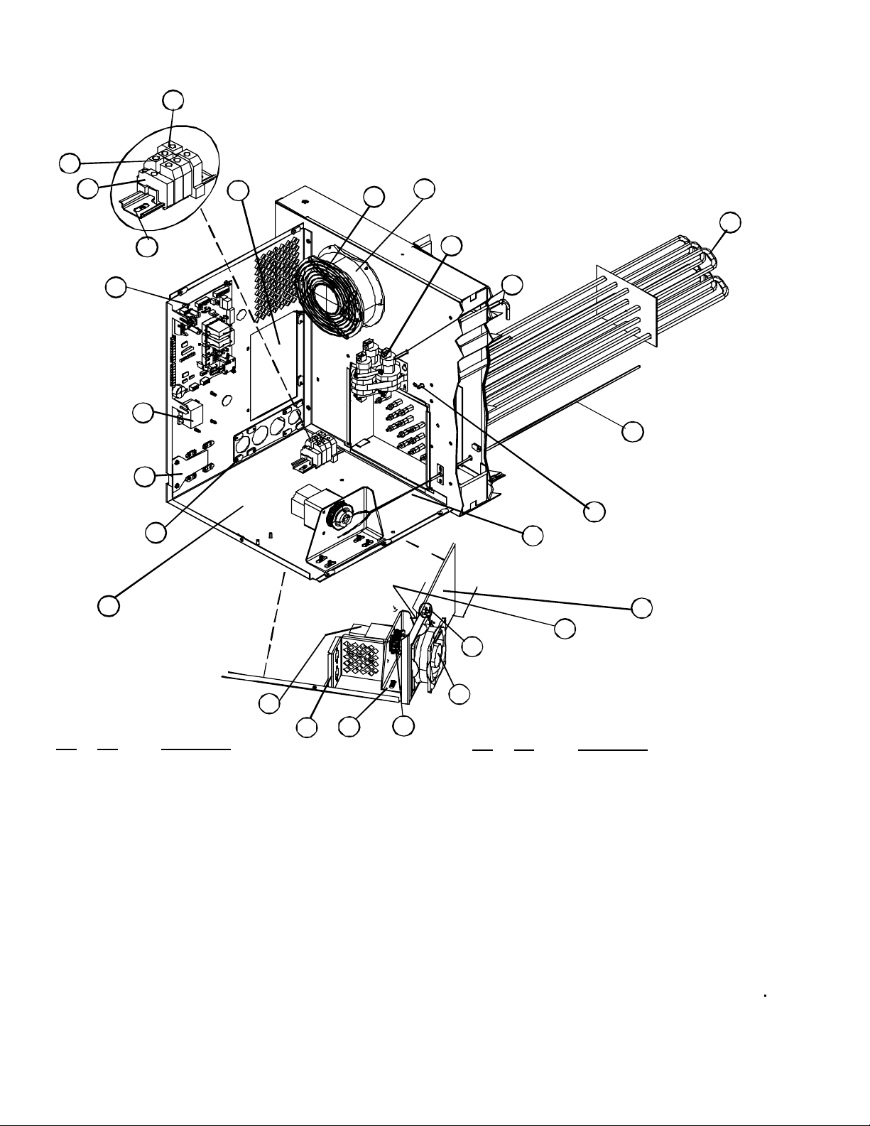
CONTROL BOX - INTERIOR VIEW
ELECTRIC OVENS-DOMESTIC, EXPORT, AND CE
M10277
Access
Box
T0321
Fan Guard,
top
1
M9609
Axial Fan, top, 7"
2
M10482
Contactor
12
M10486
Pressure
Tube Assy
22
20
M2697
M2699
M2698
M2571
M2572
M2574
M2573
Element
R7603
Hi-Limit
Thermostat
M10479
Block Off
Plate
Plate, Power
Line Adaptor
Ref. Part
No. No. Description
1 T0321 Fan Guard, top
2 M9609 Axial Fan, top, 7"
3 M10278 Interface Board
4 R7603 Hi-Limit Thermostat
5 M10479 Block Off Plate, Electric Ovens
6 M10112 Plate, Power Line Adaptor, Electric Ovens
7 M9622 Probe, RTD 20" 100 Ohms
8 R0166 Terminal Ground Block, Qty 1 per oven
9 M4542 Terminal Power Block, Qty 2 per oven
10 R1580 End Stop, Terminal Block, Qty 1 per oven
11 M9477 Din Rail, for Terminal Block mounting
12 M10482 Contactor, 60 Amp, 24V, 3 PH
13 M8991 Probe Well Assy, EGO
14 M10556 Conveyor Drive Motor
15 M10519 Motor Mount Bracket
16 M10512 Pulley, Sprocket
17 M9616 Axial Fan, bottom
18 M0571 Fan Guard, bottom
19 M10277 Access Cover, Control Box
4
5
M10112
21
Control Box
M10589 Interface Plate & Decal Kit (not pictured)
6
M10214
Bottom
Conveyor Drive Motor
M10556
Fuseholder
14
M10460
Bracket
15
23
M10519
Motor Mount
Bracket
16
M10512
Pulley
7
M9622
Probe, RTD,
20" 100 Ohms
13
7
M9622
Probe, RTD,
20" 100 Ohms
M10509
Retractable
25
Pin, Plunger
M9616
Axial Fan,
17
bottom
Ref. Part
No. Description
No.
20 M2697 Element, 208V (**Need Kits) 1 PH
20 M2699 Element, 220V (**Need Kits) 1 PH
20 M2698 Element, 240V (**Need Kits) 1 PH
20 M2571 Element, 208V (**Need Kits) 3 PH
20 M2572 Element, 240V (**Need Kits) 3 PH
20 M2574 Element, 240/415V 3 PH EXPORT
20 M2573 Element, 220/380V 3 PH EXPORT
21 M10214 Control Box Bottom
M10471 Control Box, Top Assy, not pictured
22 M10486 Pressure Tube Assy
23 M10460 Fuseholder Bracket
24 M10424 Control Box, Lower Panel
25 M10509 Retractable Pin Plunger, Locking
Probe Well
Assy, EGO
18
Fan Guard,
See page 6
M8991
M0571
bottom
M10424
24
Control Box,
Lower Panel
Page 5
AUGUST 29, 2001 5 SG2136E & G
30
r
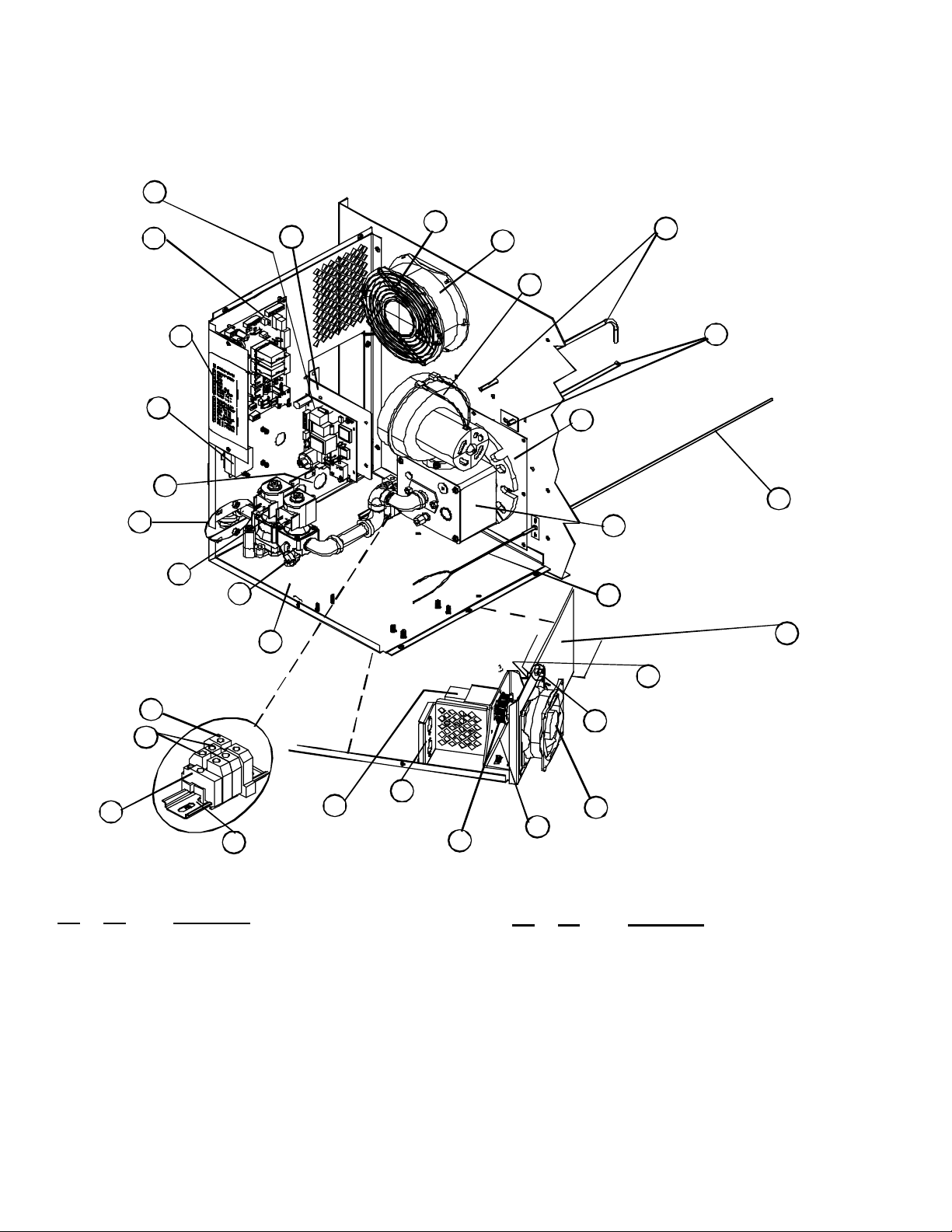
CONTROL BOX - INTERIOR VIEW
M10279
Ignition
Control
4
3
M10278
Interface
Board
M10589
Interface Plate
& Decal Kit
R7603
Hi-Limit
Thermostat
M10112
Power Line
Adaptor Plate
M10270
Block Off
Plate
M8999
Gas Valve,
Nat/LP
R0166
Terminal
Ground Block
R0164
Terminal Power
Block, Qty 2
12
R1580
End Stop
Ref. Part
No. No. Description
1 T0321 Fan Guard, top
2 M9609 Axial Fan, top, 7"
3 M10278 Interface Board
4 M10279 Ignition Control Board
5 M10489 Bracket, Ignition Control Board
6 R7603 Hi-Limit Thermostat
7 M10270 Block Off Plate, Gas Ovens
8 M10112 Plate, Power Line Adaptor, Gas Ovens
9 M9622 Probe, RTD 20" 100 Ohms
10 R0166 Terminal Ground Block, Qty 1 per oven
11 R0164 Terminal Power Block, Qty 2 per oven
12 R1580 End Stop, Terminal Block, Qty 1 per oven
13 M9477 Din Rail, for Terminal Block mounting
14 M8991 Probe Well Assy, EGO
15 M10486 Pressure Tube Assy
16 M10556 Conveyor Drive Motor
21
6
8
7
22
Flex Tubing
(Mounts here)
10
11
33488
M10214
Control Box
Bottom
13
M9477
Din Rail
23
GAS OVENS-DOMESTIC, EXPORT, AND CE
M10489
Bracket,
Igniton Control
Board
5
28
16
M10556
Conveyor
Drive Motor
Fan Guard,
26
M10460
Fuseholder
Bracket
T0321
top
1
M10512
Pulley
18
M9609
Axial Fan, top, 7"
2
M9887
Blower Assy
30
M2027
24
Burner Plate
Support
25
9
M10509
29
Retractable
Pin, Plunger
19
17
M10519
Motor Mount
Bracket
Ref. Part
No.
17 M10519 Motor Mount Bracket
18 M10512 Pulley, Sprocket
19 M9616 Axial Fan, bottom
20 M0571 Fan Guard, bottom
21 M10589 Interface Plate & Decal Kit
22 M8999 Gas Valve, Nat & LP
23 33488 Flex Tubing, 12"
24 M2027 Burner Plate Support
25 M10211 Burner Assy
26 M10460 Fuseholder Bracket
27 M10424 Control Box, Lower Panel
28 M10214 Control Box, Bottom
29 M10509 Retractable Pin Plunger, Locking
No. Description
M10471 Control Box Top Assy, not pictured,
M9887 Blower, Burne
15
M10486
Pressure
Tube Assy
M10211
Burner Assy
M9622
Probe, RTD,
20" 100 Ohms
M0571
20
Fan Guard,
bottom
M9616
Axial Fan,
bottom
see page 6
14
M8991
Probe Well
Assy, EGO
9
27
M9622
Probe, RTD,
20" 100 Ohms
M10424
Control Box,
Lower Panel
Page 6
AUGUST 29, 2001 6 SG2136E & G
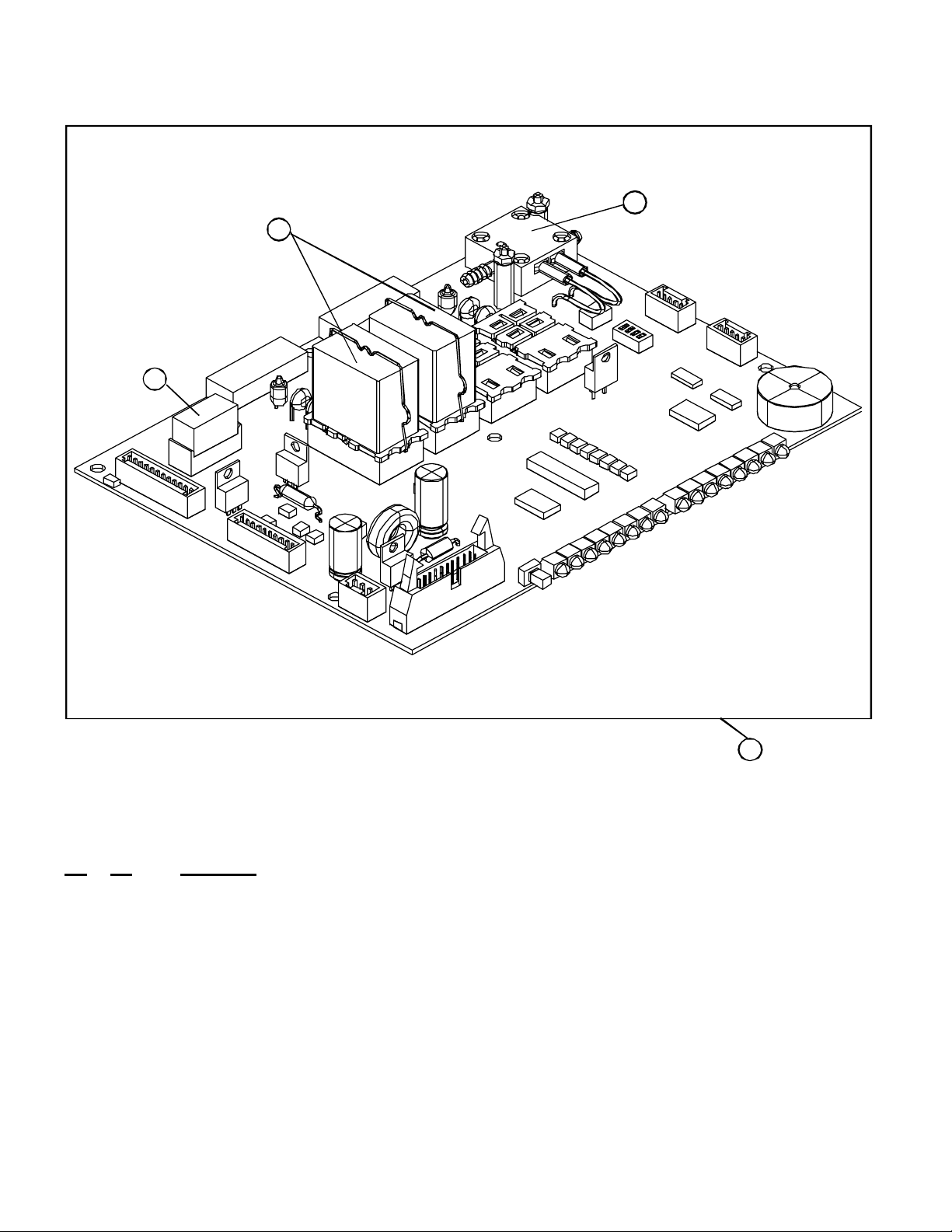
INTERFACE BOARD COMPONENTS
M10139
Heat Relay, 1 Pole
1
M9720
Relay, 2 Pole
2
3
M10165
Pressure
Switch
Ref. Part
No. No. Description
1 M10139 Heat Relay, 1 Pole
2 M9720 Relay, 2 Pole Qty 2
3 M10165 Pressure Switch
M9705 Tubing Polyurethane for pressure switch
4 M10278 Interface Board, Complete as shown above
M10278
4
Interface
Board
Page 7

AUGUST 29, 2001 7 SG2136E & G
CONTROL BOX EXTERIOR & INTERIOR TOP VIEW
DOMESTIC, EXPORT, AND CE
4
M0593
Terminal
Block
NOTE: M10471, COMPLETE TOP ASSY
M9477
Din Rail
M10488
Mounting
Bracket
1
R1580
End Stop
2
T
OP
3
VIEW
, UNDER SIDE
M9611
RTD
Converter
9
M10280
PLC Control
M10277
Access Cover
10
12
M10451
Control Box
Top
11
M9611
RTD
Converter
10
9
M10136
PLC Control
M10475
Bushing, 1/2
5
M9659
Conveyor Motor
Gear Control
M10271
6
Mounting
Plate
8
R.H. SIDE
M9608
7
Power
Supply, 24V
16
M10419
Tunnel
See Stack Assy part numbers
on page 7-9
22241
Ref. Part
No. No. Description
1 M9477 Din Rail
2 M10488 Mounting Bracket
3 R1580 End Stop
4 M0593 Terminal Block
5 M9659 Conveyor Motor Gear Control
6 M10271 Mounting Plate
7 M9608 Power Supply, 24V
8 M10475 Bushing 1/2
9 M10280 PLC Control
10 M9611 RTD Converter
11 M10451 Control Box Top
12 M10277 Access Cover
13 22241 Manifold Bracket
14 M10254 Access Panel, Control Box
15 M6035 Latch, Access Panel
16 M10419 Tunnel
13
Manifold
Bracket
14
M10254
Access
Panel,
Control Box
15
M6035
Latch
Page 8

AUGUST 29, 2001 8 SG2136E & G
GAS BURNER COMPONENTS
DOMESTIC OVENS
M9887
10
M0317
Elbow
Blower Assy
13
11
R5347
Nipple
597
Ell, 90º
12
10
M0317
Elbow
14
M10211
Burner Assy
M3219
Plastic Cap
M0282
Gas Valve,
Manual
7
2
1003
Tee 3/4
3
17876
Bushing
M8690
Bushing
1/2x 1/8
17
4588
6
Nipple, 3/4 NPT
1
4588
6
Nipple, 3/4 NPT
10809
4
Nipple, Pipe1/2 x 2
M8999
8
Gas Valve, Main
LP & Nat
15
5
M0281
Plug
9
21225
Elbow
M2835
Elbow 1/8
Ref. Part
No. No. Description
1 M3219 Plastic Cap
2 1003 Tee, 3/4
3 17876 Bushing 3/4 x 1/2
4 10809 Nipple, Pipe 1/2 x 2
5 M0281 Plug 1/8
6 4588 Nipple 3/4"
7 M0282 Gas Valve, Manual
8 M8999 Gas Valve, Main LP & Nat
9 21225 Elbow 1/4 x 1/8
10 M0317 Elbow 1/2 NPT Street Qty 3 per oven
11 R5347 Nipple 1/2 NPT x 3.00
12 597 Ell, Black 90º
13 M9887 Blower Motor Assy
14 M10211 Burner Assy
M0415 Flame Sensor, not pictured
M10593 Pilot Burner & Ignitor Assy, NAT
M10594 Pilot Burner & Ignitor Assy, LP
15 M2835 Elbow 1/8
16 33488 Flex Tubing 1/4 x 12"
17 M8690 Bushing 1/2 x 1/8
16
33488
Flex
Tubing
NOTE: M10215, Complete Stack Assy
Nat & LP
Page 9

AUGUST 29, 2001 9 SG2136E & G
GAS BURNER COMPONENTS
FOR EXPORT & CE OVENS ONLY
EXCEPT FOR FRANCE & BELGIUM, SEE PAGE 9
M9887
Blower Assy
14
4588
7
Nipple, 3/4 NPT
M3219
Plastic Cap
1
2
1003
Tee
3
17876
Bushing
4
M8690
Bushing
5
M3443
Bushing,
Export
Adapter
Ref. Part
No. No. Description
6
M2841
Fitting,
Pressure
Tap
21225
Elbow
Pressure Tap
10
M2841
Fitting,
M0282
8
Gas Valve, Manual
4588
Nipple, 3/4 NPT
7
10809
16
Nipple, Pipe1/2 x 2
6
9
M8999
Gas Valve, Main
LP & Nat
M0317
Elbow
11
M2835
17
Elbow, 1/8 NPT
Street
5
M3443
Bushing,
Export Adapter
12
18
597
Ell, 90º
13
11
M0317
Elbow
R5347
Nipple
33488
Flex
Tubing
Ref. Part
No. No. Description
15
M10211
Burner Assy, Nat
MXXXXX
Burner Assy, LP
NOTE: M10505, Complete Stack Assy
Nat & LP
1 M3219 Plastic Cap
2 1003 Tee
3 17876 Bushing
4 M8690 Bushing 1/2 x 1/8
5 M3443 Bushing Export Adapter
6 M2841 Fitting, Pressure Tap
7 4588 Nipple 3/4 NPT
8 M0282 Gas Valve, Manual
9 M8999 Gas Valve, Main LP & Nat
10 21225 Elbow 1/4 T x 1/8 NPT
11 M0317 Elbow 1/2 NPT Street Qty 3 per oven
12 R5347 Nipple 1/2 NPT x 3.00
13 597 Ell, Black 90º
14 M9887 Blower Motor Assy
15 M10211 Burner Assy
M0415 Flame Sensor, not pictured
M10593 Pilot Burner & Ignitor Assy, NAT
M10594 Pilot Burner & Ignitor Assy, LP
16 10809 Nipple, Pipe 1/2 x 2
17 M2835 Elbow 1/8 NPT Street
18 33488 Flex Tubing 1/4 x 12"
M10700 Gas Conversion Kit, LP to NAT CE & Gen Exp
M10701 Gas Conversion Kit, Nat to LP CE& Gen Exp
M10505 Complete Stack Assy, Nat & LP as shown above
Page 10

AUGUST 29, 2001 10 SG2136E & G
GAS BURNER COMPONENTS
FRANCE & BELGIUM OVENS ONLY
M9887
Blower Assy
14
Ell, 90º
12
R5347
Nipple
597
13
11
M0317
Elbow
33488
16
Flex Tubing
15
M10211
Burner Assy
NOTE: M10506, Complete Stack Assy
Nat & LP
Plastic Cap
M0282
Gas Valve,
Manual
2
4
1003
Tee 3/4
5
M8690
Bushing
1/2 x 1/8
6
M3443
Bushing,
Export
Adaptor
M3219
1
M2841
Fitting,
Pressure
Tap
4588
3
Nipple, 3/4 NPT
M10507
9
Nipple & Orifice
Assy
M8999
10
Gas Valve, Main
LP & Nat
M0317
Elbow
11
8
M2835
18
21225
Elbow
7
17876
Bushing
3/4 x 1/2
17
Elbow 1/8
M3443
6
Bushing, Export Adaptor
M2841
8
Fitting,
Pressure Tap
Ref. Part
No. No. Description
1 M3219 Plastic Cap
2 M0282 Gas Valve, Manual
3 4588 Nipple, 3/4 NPT
4 1003 Tee 3/4
5 M8690 Bushing 1/2 x 1/8
6 M3443 Bushing, Export Adapter
7 17876 Bushing 3/4 x 1/2
8 M2841 Fitting, Pressure Tap
9 M10507 Nipple & Orifice Assy
10 M8999 Gas Valve, Main LP & Nat
11 M0317 Elbow 1/2 NPT Street Qty 3 per oven
12 R5347 Nipple
13 597 Ell, 90º
14 M9887 Blower Motor Assy
Ref. Part
No. No. Description
15 M10211 Burner Assy
M0415 Flame Sensor, not pictured
M10593 Pilot Burner & Ignitor Assy, NAT
M10594 Pilot Burner & Ignitor Assy, LP
16 33488 Flex Tubing 12"
17 M2835 Elbow 1/8
18 21225 Elbow
M10702 Gas Conversion Kit, LP to Nat
France and Belgium
M10708 Gas Conversion Kit, Nat to LP
France and Belgium
M10506 Complete Stack Assy, Nat & LP
as shown above
Page 11

AUGUST 29, 2001 11 SG2136E & G
M9829
Temperature Probe
4
M2870
Motor Assy, CCW
DOM
or
M2872
Motor Assy, CCW
CE or Export
M10580
Air Diverter
CONVECTION COMPONENTS
DOMESTIC, EXPORT & CE
M2871
Motor Assy, CW
DOM
or
M2873
Motor Assy, CW
1
8
CE or Export
2
M10304
3
Air Slide
6a
M10629
5a
M10619
Air Plate Assy, LH
R-L Belt Dir.
Air Plate Assy, RH
R-L Belt Dir.
REAR VIEW -
MOTORS
3
1
M2870
Motor Assy, CCW
DOM
or
M2872
Motor Assy, CCW
CE or Export
Ref. Part
No. No. Description
1 M2870 Motor & Blower Assy, CCW Domestic
2 M2871 Motor & Blower Assy, CW Domestic
1 M2872 Motor & Blower Assy, CCW CE, Gen Exp
2 M2873 Motor & Blower Assy, CW CE, Gen Exp
M10585 Blower Insulation Kit
3 M10304 Air Slide, Qty 2 per oven
4 M9829 Probe, RTD 2" 100 Ohms
5 M10631 Air Plate Assy, LH L-R Belt Direction
6 M10623 Air Plate Assy, RH L-R Belt Direction
5a M10619 Air Plate Assy, LH R-L Belt Direction
6a M10629 Air Plate Assy, RH R-L Belt Direction
24613 Hook, Air Pan not pictured
2
M2871
Motor Assy, CW
DOM
or
M2873
Motor Assy, CW
CE or Export
M10304
Air Slide
Burner Tube
9
M2140
5
M10631
Air Plate Assy, LH
L-R Belt Dir.
7
M10597
Nozzle Assy, (Qty 5)
Ref. Part
No. No. Description
7 M10597 Nozzle Assy, Qty 5 per oven
8 M10580 Air Diverter, not shown,
located in between motors.
9 M2140 Burner Tube Assy
6
M10623
Air Plate Assy, RH
L-R Belt Dir.
Page 12

AUGUST 29, 2001 12 SG2136E & G
M10509
Retractable
Locking Pin
12
1
M10513
Pulley, Sprocket
2
M0108
Sprocket 3/4 Bore
Qty 5
M0108
Sprocket 3/4 Bore
Qty 5
6
Crumb Pan, Drive
for Single or Bottom Unit
M5335
CONVEYOR COMPONENTS-SINGLE BELT UNITS
CLOSE-UP VIEWS
9
M0122
11
Bearing,
Rulon
M5071 Crumb Pan, Idle
M2388
Belt Tensioner Assy,
contains spring,
sleeve and shaft
4
3
M2013
Shaft, Conveyor,
Drive
2
M10515,
7
Conveyor Assy, Drive
M0108
Sprocket 3/4 Bore
Qty 5
8
M5066, Conveyor Assy, Idle
4
M2388
Belt Tensioner Assy,
contains spring,
sleeve and shaft
5
for Single or Bottom Unit
2
3a
M2014
Shaft,
Conveyor Idle
masterlink. Call Tech. Service for
10
5a
M6996 Crumb Pan, Idle
for Top or Middle Unit
NOTE: Cut here to create a
additional information.
1-800-331-5842
M4309
Product Stop
10
M2740
Belt,
Conveyor
(sold per foot,
total 11 feet)
6a
Crumb Pan, Drive
for Top or Middle Unit
Ref. Part
No. No. Description
1 M10513 Pulley, Sprocket
M10572 Belt, for pulley 16"
2 M0108 Sprocket, 3/4 Bore, 10 per unit, 5 per conveyor assy
3 M2013 Shaft, Conveyor Drive Side
3a M2014 Shaft, Conveyor Idle Side
4 M2388 Belt Tensioner Assy
5 M5071 Crumb Pan, Remote, Idle for Single or Bottom Units
5a M6996 Crumb Pan, Remote, Idle for Top or Middle Units
6 M5335 Crumb Pan, Remote, Drive for Single or Bottom Units
6a M6995 Crumb Pan, Remote, Drive for Top or Middle Units
M10581 Crumb Pan, Integral, Drive for Top or Middle Units
M10570 Crumb Pan, Integral, Idle for Top or Middle Units
7 M10515 Conveyor Assy, Drive Side
8 M5066 Conveyor Assy, Idle Side
M6995
M2388
Belt Tensioner Assy,
contains spring,
sleeve and shaft
4
Depicts a blown-up section of belt,
M2740
10
M2740
Belt,
Conveyor
(sold per foot,
total 11 feet)
Ref. Part
No. No. Description
9 M4309 Product Stop
10 M2740 Belt, Wire S/S for Conveyor Assy 21" wide
Sold per foot, total 11 feet
11 M0122 Bearing, Rulon, 4 per unit, 2 per conveyor
assy
12 M10509 Retractable Locking Pin, for conveyor shaft
Page 13

AUGUST 29, 2001 13 SG2136E & G
CONTROL COMPONENTS
DOMESTIC, EXPORT, AND CE
FRONT VIEW OF "MANUAL" CONTROL
OPTION
M10137
Manual Control Assy, Remote
or
M10138
Menu Control Assy, Remote
1
REMOTE CONTROL OPTION ONLY
FRONT VIEW OF "MENU" CONTROL
OPTION
3
M9828
Remote Mounting
2
M9712
Docking Station
Remote Control
Bracket Assy
Ref. Part
No. No. Description
1 M10137 Control Assy, Manual
1 M10138 Control Assy, Menu
2 M9712 Docking Station, Remote Control
3 M9828 Remote Mounting Bracket Assy
NOTE: Decals are not available separately. You must
purchase the entire control assy.
4
Harness, Display
Ref. Part
No. No. Description
M9836 Remote Cable Assy, 10 foot
M9837 Remote Cable Assy, 50 foot
M9722 Harness, PLC to Interface Board4
4 M9723 Harness, Display
M9836 Remote Cable Assy, 10 foot
M9837 Remote Cable Assy, 50 foot
M9722 Harness, PLC to Interface Board
M10151 Power Circuit Board, Remote Controls
M10153 Power Circuit Board, Integral Controls
M9723
Page 14

AUGUST 29, 2001 14 SG2136E & G
CONTROL REAR & FRONT VIEW
DOMESTIC, EXPORT, AND CE
M10418
4
Drip Shield
3
M3299
REAR VIEW OF CONTROL
Bracket,
for high limit
2
M0635
Thermal Switch,
HIgh Limit
1
M10137
Control Assy, Manual
or
M10138
Control Assy, Menu
M10415
Housing,
Computer Display
IntegralOption
Ref. Part
No. No. Description
1 M10137 Control Assy, Manual
1 M10138 Control Assy, Menu
2 M0635 Thermal Switch, High Limit
3 M3299 Bracket, for Switch
4 M10418 Drip Shield
5 M10415 Housing, Computer Display Integral Option
FRONT VIEW OF CONTROL
5
Page 15

AUGUST 29, 2001 15 SG2136E & G
M10257
Latch
1
L.H. SIDE
VIEW OF
ACCESS
ANEL
P
M2398
Hinge Pin, LH
M2399
Hinge Pin, RH
(Kit M2801 includes 1 each)
3
M10251
2
Latch Keeper
DOOR COMPONENTS
EXPLODED VIEW
FRONT VIEW OF ACCESS PANEL
1016470
Nameplate
7
16470
Nameplate
4
M10281
Access Panel w/door, shown
or
M10272
Access Panel, w/o door
5
M7000
False Front,
Solid
6
M7001
False Front,
for sandwich
door
Ref. Part
No. No. Description
1 M10257 Latch, Access Panel
2 M10251 Latch Keeper, Access Panel
3 M2398 Hinge Pin, LH
3 M2399 Hinge Pin, RH
3 M2801 Hinge Pin Kit, RH & LH
Contains 1 each of M2398 & M2399
4 M10281 Access Panel w/sandwich door
M10272 Access Panel w/o sandwich door,
not pictured
5 M7000 False Front, Solid
6 M7001 False Front, w/sandwich door opening
7 16470 Nameplate
8 M10290 Sandwich Door, Glass 22" w/handle
9 M4582 Pivot Plate, for sandwich door LH
10 M4581 Pivot Plate, for sandwich door RH
11 M4275 Handle Kit, for sandwich door
Pivot Plate LH
10
M4581
M10290
Sandwich Door,
8
Glass 22"
9M4582
Pivot Plate RH
11
M4275
Handle Kit, 22"
Page 16

AUGUST 29, 2001 16 SG2136E & G
EXTERIOR VIEW & ACCESSORIES
EXPLODED
Access Panel
M10419
Tunnel
(under conveyor)
4
M10254
Assy, Control
Box
3
See page 13 for Door
Components breakdown.
2
M6255
Body Top
M6220
1
Body Back
M10583
Chimney Kit
Double Ovens
9
OR
M10584
Chimney Kit
Triple Ovens
10
NOTE: See page 12
for Controller breakdown
Ref. Part
No. No. Description
1 M6220 Body Back
2 M6255 Body Top
3 M10254 Access Panel Assy, Control Box
4 M10419 Tunnel Assy
5 21391 Legs, Set of 4, 23 1/4" Single Ovens
6 21390 Legs, Set of 4, 17 1/4" Double Ovens
7 22067 Triple Base & casters, Set of 4, Triple Ovens
14444 Casters, Cradle, Triple Ovens
NOTE: Legs or caster kits must be ordered in
addition to your stacking kit. See page 17.
21242 Gas Installation Hose, 48" Quick Disconnect
21826 Gas Installation Hose, 36" Quick Disconnect
6
21390
Legs 17 1/4"
Double Ovens
8
M10582
Chimney Kit
Single Ovens
Ref. Part
No. No. Description
8 M10582 Chimney Kit, Single Ovens
9 M10583 Chimney Kit, Double Ovens
10 M10584 Chimney Kit, Triple Ovens
7
22067
Triple Base
w/Casters
5
21391
Legs 23 1/4"
Single Ovens
M7002 Product Extension 6"
M6997 Product Extension 12"
NOTE: Chimney Kits must be ordered in additon
to your stacking kit. See page 17.
Page 17

AUGUST 29, 2001 17 SG2136E & G
STACKING KITS
NOTE: STACKING KITS INCLUDE ALL COMPONENTS
DEPICTED HERE - EXCEPT LEGS.
1
M7887
Alignment
Pins
Set of 4
2
M10586
Stacking Kit,
Remote Ovens
OR
3
M10587
Stacking Kit,
Integral Ovens
Ref. Part
No. No. Description
1 M7887 Alignment Pins, Set of 4
2 M10586 Stacking Kit, Remote Computer Ovens
3 M10587 Stacking Kit, Integral Computer Ovens
NOTE: Stacking Kits include all stacking rails, stacking trims,
4 M10588 Heat Shield Assy, Integral Ovens only
NOTE: Remote ovens do not utilize a heat shield kit. There is no
Stacking Rails
NOTE: See page 16
for legs & casters and
chimney kit breakdowns.
heat shield & brackets, and crumb pans with all
applicable hardware. Legs or caster kits and chimney
kits must be ordered separately. See page 16.
need for one, because there is no tunnel to attach the
heat shield on to.
Stacking Trim,
Control Box
4
M10588
Heat Shield
Assy, Integral
Ovens Only
Control Box
Stacking
Spacer
Page 18

 Loading...