

Page 1

KCO -25E
CONVECTION OVEN
INSTALLATION -- OPERATION -- MAINTENANCE
BLODGETT OVEN COMPANY
www.blodgett.com
44 Lakeside Avenue, Burlington, Vermont 05401 USA Telephone (800) 331-5842, (802) 860-3700 Fax: (802)864-0183
PN 31594 Rev C (6/01)
E 2000 --- G.S. Blodgett Corporation
Page 2

IMPORTANT
WARNING: IMPROPER INSTALLATION, ADJUSTMENT,
ALTERATION, SERVICE OR MAINTENANCE CAN CAUSE
PROPERTY DAMAGE, INJURY OR DEATH. READ THE INSTALLATION, OPERATING AND MAINTENANCE INSTRUCTIONS THOROUGHLY BEFORE INSTALLING OR
SERVICING THIS EQUIPMENT
FORYOURSAFETY
Do not store or use gasoline or other flammable vapors or
liquids in the vicinity of this or any other appliance.
The information contained in this manual is i mportant for the proper
installation, use, and maintenance of this oven. Adherence to these
procedures and instructions will result in satisfactory baking results
and long, trouble free service. Please read this manual carefully and
retain it for future reference.
Errors: Descriptive, typographic or pictorial errors are subject to correc-
tion. Specifications are subject to change without notice.
Page 3

THE REPUTATION YOU CAN COUNT ON
For over a century and a half, The Blodgett Oven Company has been building
ovens and nothing but ovens. We’ve set the industry’s quality standard for all
kinds of ovens for every foodservice operation regardless of size, application
or budget. In fact, no one offers more models, sizes, and oven applications
than Blodgett; gas and electric, full-size, half-size, countertop and deck, convection, Cook’n Hold, Combi-Ovens and the industry’s highest quality Pizza
Oven line. For more information on the full line of Blodgett ovens contact your
Blodgett representative.
Page 4

Your Service Address: Model:
Serial Number:
Your oven was installed by:
Your oven’s installation was checked by:
Page 5

Table of Contents
INTRODUCTION
Electrical Specifications 2.................................................
Oven Approvals 3........................................................
Pre-Installation 4.........................................................
Delivery 4...............................................................
INSTALLATION
Oven Location 5.........................................................
Electrical
Connections 5...........................................................
Oven Assembly 6.........................................................
OPERATION
General Guidelines for Operating Personnel 8................................
Oven Controls 9.........................................................
Display Messages 9.......................................................
Oven Operation 10........................................................
Product Programming 11...................................................
MAINTENANCE
Cleaning the Oven 12......................................................
Preventative Maintenance 12................................................
Troubleshooting Guide 13..................................................
Page 6

INTRODUCTION
CONNECTIO
N
ELECTRICAL SPECIFICATIONS
KIOSK CONVECTION OVEN KCO-25E
AMPERES
KW/SECTION VOLTS (60 HZ) PHASE
3.0 208 1 15 --- 15 14
* Refer to Page 4 in this manual for Electrical Connection specifications
Load ratings are double the above data for Double Stacked units.
L1 L2 L3
ELECTRICAL
AWG*
2
Page 7

INTRODUCTION
OVEN APPROVALS
KCO-25E
Single
KCO-25E
Double Stacked
3
Page 8

INTRODUCTION
PRE -INSTALLATION
THE INSTALLATION INSTRUCTIONS
CONTAINED HEREIN ARE FOR THE USE
OF QUALIFIED INSTALLATION PERSONNEL ONLY. INSTALLATION OR SERVICE
BY OTHER THAN QUALIFIED PERSONNEL MAY RESULT IN DAMAGE TO THE
OVEN AND/OR INJURY TO THE OPERATOR.
Qualified installation personnel are individuals, a
firm, a corporation, or a company which either in
person, or through a representative are engaged in
and responsible for :
D
The installation of electrical wiring from the electric meter, main control box, or service outlet, to
the appliance. Qualified installation personnel
must be experienced in such work, familiar with
all precautions required, and have complied with
all requirements of state or local authorities having jurisdiction. Reference: National Electrical
Code, ANSI/NFP A 70 --- Latest Edition and/or
Canadian Electrical Code CSA C22.1 as applicable.
DELIVERY
All Blodgett Ovens are strapped on heavy wooden
skids, and surrounded by tri-wall cartons to prevent
shipping damage. When tendered to the carrier,
each unit has been carefully inspected and packaged.
Upon delivery of your Blodgett oven:
D
Inspect the shipping container for ex ternal damage. Any evidence of damage should be noted on
the delivery receipt, which must be signed by the
driver.
D
Uncrate the oven and check for any concealed
damages. Carriers will accept claims for damages,
if notified within 15 days of delivery, and the carton is retained for inspection.
The Blodgett Oven Co. cannot accept responsibility for loss or damages suffered in
transit. The carrier assumed full responsibility for delivery in good order, when the shipment was accepted. However we are prepared to assi st you in your claim.
D
The ventilation of this oven should be in accordance with local codes. In the absence of local
codes, refer to the National ventilation code
titled, “Standard for the Installation of Equipment for the Rem ov alof Smoke and Grease Laden
Vapors from Commercial Cooking Equipment”,
NFPA -9 6 -Latest Edition.
4
Page 9

OVEN LOCATION
INSTALLATION
The well planned and proper placement of the oven
will result in long term operator convenience and satisfactory performance. It is therefore, urged that adequate thought be given to the location of the oven
prior to its delivery for installation.
Placethe oven in an area which is accessible for proper operation and servicing.
It is also essential that ventilation air not be obstructed in any way if proper operation is to be assured. Tripping of the blower motor thermal overload protective device is caused by excessive ambient
temperature in the motor compartment resulting
from insufficient ventilation. Such a condition must
be corrected immediately if permanent damage to
theovenistobeavoided.
ELECTRICAL
CONNECTIONS
This unit is supplied with a power cord and L6-20P
NEMA plug (3 prong grounding 250 volt). It is intended for use with a L6-20R NEMA receptacle.
Before making any connections to this oven, check
the rating plate attached to the back of the oven to
assure that the voltage, phase and KW rati ng are
compatible with the electrical supply. See the table
on Page 2 for electrical specifications.
WARNING
THIS APPLIANCE IS EQUIPPED
WITH A THREE-PRONG GROUNDINGTYPEPLUGFORYOURPROTECTION AGAINST SHOCK HAZARD. THE APPLIANCE MUST BE
PLUGGED DIRECTLY INTO A
PROPERLY GROUNDED THREE
PRONG RECEPTACLE. DO NOT
CUT OR REMOVE THE GROUNDING PRONG FROM THE PLUG.
5
Page 10
INSTALLATION
OVEN ASSEMBLY
MOUNTING OVEN ON 4” LEGS:
NOTE:Before operating the KCO-25E, the unit must
be mounted on the legs provided.
1. Tilt the oven onto its back.
2. Screw 4” legs into 4 holes located near oven corners.
3. Use a tool to tighten the hex nut at the top of
each leg.
4. Lift oven forward onto legs.
LEVELING THE OVEN:
After the oven is mounted on the legs it should be leveled by screwing the adjustable leg feet in or out as
necessary. Check with a spi rit level placed on the top
of the oven.
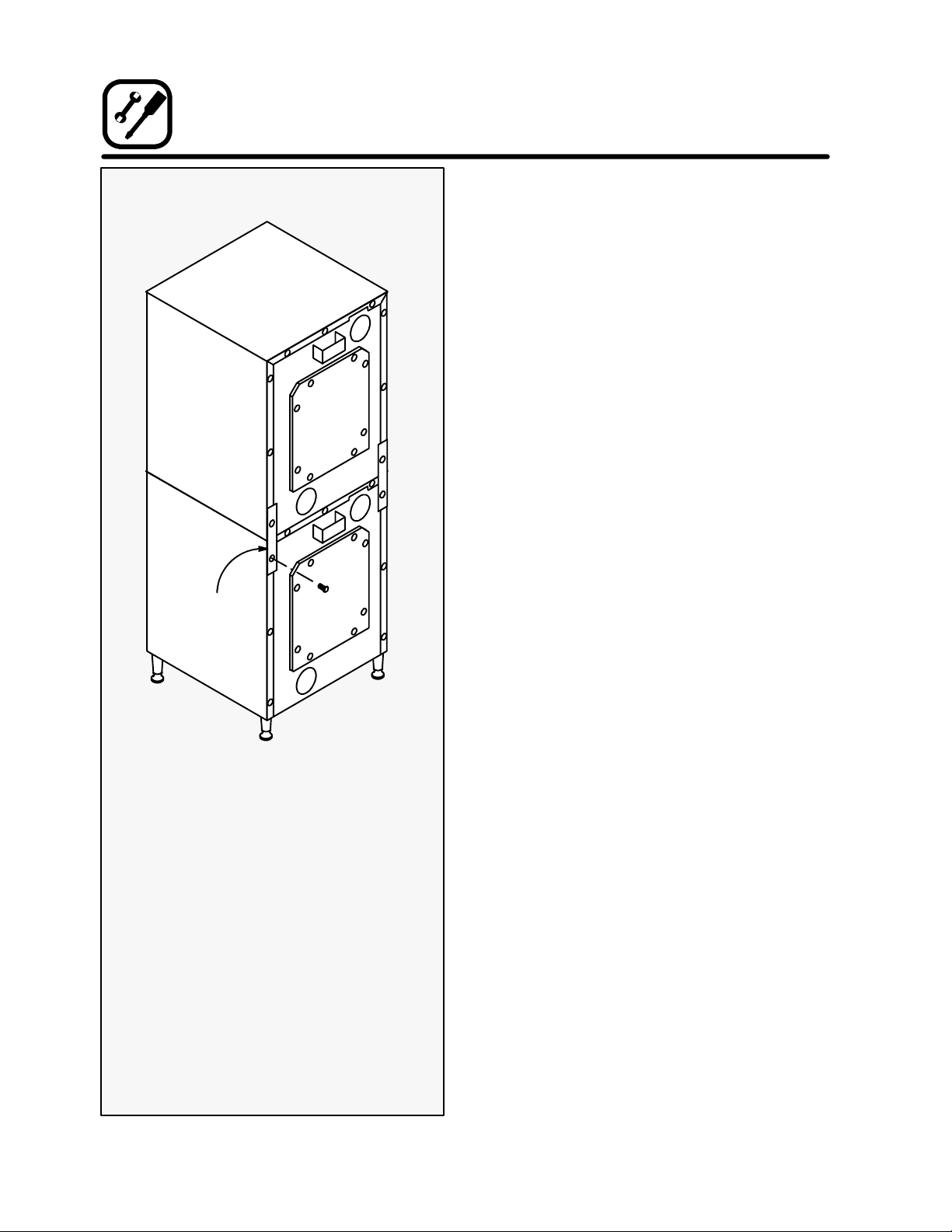
DOUBLE STACKING:
1. Mount the lower section on legs as directed.
Stacking
Angle
DOUBLE STACKING
2. Set the upper section on the lower section.
3. Remove the bottom left and right screws from
the upper section. Remove the top left and right
screws from the lower section.
4. Attach the two stacking angles with the screws
removedinStep2.
6
Page 11

DOOR RELOCATION
The KCO-25E is shipped with the door hinged on t he
right side. If left hand operation is necessa ry use the
following procedure to relocate the door.
1. Shut off the oven power switch.
2. Remove the door as follows:
a.) Loosen the two upper door bolts.
b.) Loosen the two lower door bolts. Remove
the top bolt.
c.) Slide the remaining lower door bolt up in
its slotted hole.
NOTE: The lower door pin attached to
the bolt will release from the
bushing in the unit frame.
d.) Tilt the door (with the 5/16” thick washer)
away from the unit.
e.) Lower the door so that the upper door pin
drops out of the bushing in the unit frame.
3. Relocate the hinge and catch parts as follows:
a.) Remove the trim plates located on the
frame opposite the door pins. The two
plates are attached with one screw each.
NOTE: This will expose the pin/bushing
holes for the alternate door location.
b.) Move the two brass door bushings in the
unit frame to the alternate door pin/bushing holes.
c.) Attach the trim plates to the frame over
the two holes where the bushings were.
Mounting holes are provided at the new
locations.
NOTE: Note that the upper trim plate has
a slotted air opening.
d.) Move the door catch plate located on the
upper door frame to the opposite side of
the oven cavity. Mounting holes are provided at the new location for the catch
plate (two screws).
4. Reattach the door as follows:
a.) Attach the door to the unit at the relo-
cated bushings by reve rsing the steps
above.
b.) Tighten the four door bolts hand tight
only.
INSTALLATION
5. Relocate the handle and plate assembly on the
door as follows:
a.) Remove the four hex head screws which
attach the handle plates to the door.
b.) Twist the upper plate around the door
handle by at least 90_.
c.) Lower the handle a nd plate assembly out
of the door.
d.) Flip the handle and plate assembly 180_.
e.) Reattach the assembly by inserting the
roller latch plate into the opening at the
door top.
f.) Twist the lower plate around the door
handle to its original mounting position.
g.) Reinstall the four screws through the han-
dle plate into the door.
6. Adjust the door as follows:
a.) Close the door and check that the roller
latch secures the door tightly.
b.) Adjust the catch plate (by its slotted
mounting holes) if necessary.
7. Turn the unit on and verify that the door proximity switch shuts off the fan when the door opens.
Door Catch
Under Overhand
Handle & Plate
Assembly
Door Bolt
Trim Plate
7
Page 12

OPERATION
GENERAL GUIDELINES FOR
OPERATING PERSONNEL
TO OBTAIN OPTIMUM PERFORMANCE FROM
THEKCO-25E,PLEASEOBSERVETHEFOLLOWING PROCEDURES AND SUGGESTIONS.
D
Follow the Time and Temperature recommendations provided for the product to be prepared in
the oven. Cooking at higher temperatures will not
reduce cooking time, it will produce unsatisfactory results. Time will vary with the amount of product loaded, the t ype of pan and the temperature.
Record times and temperatures which provide
best results for future reference.
D
Three rack positions are available in the oven.
D
Do not place a pan or aluminum foil on the bottom of the oven. This will obstruct the flow of air
andresultinunevenbaking.
D
When baking, weigh the product to assure equal
quantities in all pans or uneven results may occur.
THE INFORMATION CONTAINED IN
THIS SECTION IS PROVIDED FOR THE
USE OF QUALIFIED OPERATING PERSONNEL. QUALIFIED OPERATING PERSONNEL ARE THOSE WHO HAVE CAREFULLY READ THE INFORMATION CONTAINED IN THIS MANUAL, ARE FAMILIAR WITH THE FUNCTIONS OF THE
OVEN AND/OR HAVE HAD PREVIOUS
EXPERIENCE WITH THE OPERATION
OF THE EQUIPMENT DESCRIBED. ADHERENCE TO THE PROCEDURES RECOMMENDED HEREIN WILL ASSURE
THE ACHIEVEMENT OF OPTIMUM PERFORMANCE AND LONG, TROUBLE FREE SERVICE.
8
Page 13

OPERATION
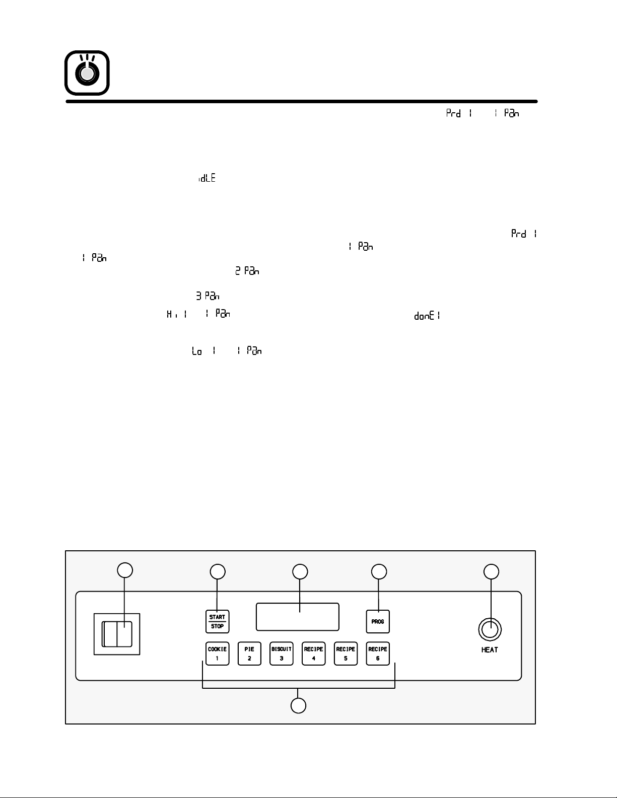
OVEN CONTROLS
1. POWER ON/OFF - Controls the operation of
the oven. If the power switch is lighted the power
to the unit is on. If the power switch is not lit, the
power to the unit is off.
2. DISPLAY --- Displays time and temperature and
other information related to oven function.
Time is displayed in minutes and seconds and
counts down.
3. START/STOP KEY --- Starts or stops the selected product key program.
4. PRODUCT KEYS (1-6) --- Associates a time and
temperaturewith a specific productfor each key.
5. PROGRAM KEY --- Accesses the program mode
to set or change the time or temperature of a
product key.
6. HEAT LIGHT --- Indicates that the elements are
operating.
DISPLAY MESSAGES
Indicates the oven is heating to, or cycling at
the idle temperature. (Temperature the
oven maintains when not in use).
Indicates the oven temperature is too high
for the selected product recipe. Wait until
is di splay ed.
Indicates the oven temperature is too low
for the selected product recipe. Wait until
is di splay ed.
Indicates the oven has reached the selected
recipe temperature. Ready for productload.
Indicates the number of pans of the same
product in one load.
Indicates the timer has counted down to
00:00 and the product is done.
Indicates the control is ready to accept the
code and enter the program mode.
Indicates the control has entered t he program mode.
Indicates the cook temperature for a product key can be programmed.
Indicates the cook time for a single pan can
be programmed.
Indicates the cook time for two pans can be
programmed.
Indicates the cook time for three pans can be
programmed.
Indicates an open or shorted probe.
1
23 5
6
4
9
Page 14
OPERATION
OVEN OPERATION
NOTE:The display examples given below are for a
single pan of product 1.
1. Toggle the POWER SWITCH (1) to the ON
position. T he display reads
to, or cycles at the programmed idle temperature.
2. Select one of the six (6) programmed PRODUCT KEYS (4). Press the key once if one pan of
the product is to be loaded. The display reads
. Press twice if two pans of the product are
to be loaded. The display reads
three times if three pans of the product are to be
loaded. The display reads
The display flashes
oven temperature is greater than the programmed temperature for the selected product
key. The display flashes
current oven temperature is lower than the programmed temperature for the selected product
key.
as the oven heats
.Press
.
and if the current
and if the
When the display flashes
unit is at the programmed temperature.
3. If the wrongproduct i s selected repeat Step 2 using the correct PRODUCT KEY (4).
If the product choice is correct but the number
of pans is wrong; press the appropriate PRODUCT KEY (4) until the display reads the correct
number of pans.
4. When both the product selection and number of
pans are correct, and the display flashes
and ; load the product i nto the oven. Close
the door.
5. Press the START/STOP key (3) to begin the
product countdown. The display flashes as the
time counts down.
6. The display flashes
when the product has timed out.
7. Press the START/STOP key (3) to turn off the
buzzer.
8. Remove t he product.
and the buzzer sounds
and the
1
23 5
6
4
10
Page 15

OPERATION
PRODUCT PROGRAMMING
NOTE: The example given below is for Product 1.
To enter the Program Mode:
1. Press and hold the PROGRAMkey (5) for 3 seconds. The buzzer sounds and the display reads
.
NOTE:If the programkey is pressedand NOTheld
the controller displays the current oven
temperature and the program mode will
not be accessed.
2. When the display reads
KEYS (4) to enter the program mode access
code.Theaccesscodeis:1111
3. Press the PROGRAM key (5). The display reads
.
To program a selected Product Key:
1. Press the desired PRODUCT key (4). The control flashes
key) then displays the current cook temperature.
The new cook temperature may now be entered.
Use product key 5 to increase the temperature.
Use product key 6 to decrease the temperature.
If the key is pushed quickly the units will increase/decrease by one. If the key is held, the
units will increase/decrease by one to the nearest
ten. The units will then increase/decrease by ten.
When the desired temperature is reached press
the PROGRAM key (5) to save the new temperature.
2. T he control flashes
rent t ime for a single pan of product.
The new cook time for a single pan of product
may now be entered in minutes and seconds. Use
product key 5 to increase the time. Use product
key 6 to decrease the time.
When the desired time is reached press the
PROGRAM key (5) to save the new time.
3. T he control flashes
rent time for two pans of product.
The new cook time for two pans of product may
now be entered in minutes and seconds. Use
product key 5 to increase the time. Use product
key 6 to decrease the time.
When the desired time is reached press the
PROGRAM key (5) to save the new time.
(number of selected product
use the PRODUCT
then displays the cur-
then displays the cur-
4. T he control flashes
rent t ime for three pans of product.
The new cook time for three pans of product may
now be entered in minutes and seconds. Use
product key 5 to increase the time. Use product
key 6 to decrease the time.
When the desired time is reached press the
PROGRAM key (5) to save the new time.
5. All items for the selected product key have now
been programmed. The display reads
NOTE: Another product key may be programmed
at this time by repeating Steps 1-4.
To ex i t th e P r o gr a m M o d e :
1. After the last product key has been programmed, press the PROGRAM key (5) to exit
the program mode. The display reads
then displays the cur-
.
.
PRESET PROGRAMMING
The product keys have been preprogrammed at the
factory as follows:
Recipe
1 325_F 15:00 17:00 17:00
2 400_F 15:00 16:00 17:00
3 425_F 16:00 18:00 18:00
4 350_F 00:00 00:00 00:00
5 350_F 00:00 00:00 00:00
6 350_F 00:00 00:00 00:00
Tem p. 1Pan 2Pan 3Pan
RESET DEFAULT PROGRAMMING
To reset the control to the default values listed above:
1. Press and hold PROGRAM key for 3 seconds.
The buzzer sounds and the display reads
NOTE:If the programkey is pressedand NOTheld
the controller displays the current oven
temperature and the program mode will
not be accessed.
2. When the display reads
KEYS to enter the reset default programming
code.
Thecodeis:6662
The controller will reset to the default settings.
3. Press the PROGRAM key (5) to exit the reset
mode.
use the PRODUCT
.
11
Page 16

MAINTENANCE
CLEANING THE OVEN
On the stainless exterior, deposits of baked on splatter may be removed with any of the following elements: Grade FFF Italian Pumice, Liquid Nu Steel,
Permapass, Samea or Cameo paste, Nu Steel, or DuBois Temp. Heat tint and heavy discoloration may be
removed with one of the following: Penny-Brite,
Copper-Brite, DuBois Temp., Paste Nu Steel, 5 to
15% phosphori c acid. Apply cleaners when the oven
is cold, and always rub with the grain of the metal.
The racks and rack supports may be cleaned by removingthem from the oven and soaking them in a solution of ammonia and water.
Care should be taken to keep liquids away from temperature probes, heating elements etc. and avoid
spraying the oven’s electrical connections and thermostat.
PREVENTATIVE
MAINTENANCE
The best preventative maintenance measures are,
the proper installation of the equipment and a program for routinely cleaning the ovens. This oven requires no lubrication, however, the venting system
should be checked annually for possible deterioration. If maintenance or repairs are required, they
should only be performed by qualified service personnel.
Remember: Always disconnect the power supply before cleaning or servicing the appliance!
12
Page 17

TROUBLESHOOTING GUIDE
SYMPTOM POSSIBLE CAUSE(S) SUGGESTED REMEDY
S
Blower motor not runni ng
S
Controller displays PROB
S
Motor is running: No Heat
S
No power to oven
S
Door is open
S
Door switch malfunction
S
Motor burned out
S
Short or open temperature
probe
S
Loose probe connections at
computer controller
S
Internal problem with controller
S
Loose wire between element
and relay
S
Element burned out
S
Element relay malfunction
S
Malfunction in controller
thermostat
S
Hi limit thermal switch opened
MAINTENANCE
S
Press POWER ON/OFF key
S
Close the door
S
*
S
*
S
*
S
*
S
*
S
*
S
*
S
*
S
*
S
*
S
Oven on --- Control not workingSComputer controller not
properly installed
S
Internal problem with computer
controller
S
Baking Problems - -- Product
too light or dark
* Denotes remedy is a difficult operation and should be performed by qualified personnel only. It is recommended, however, that All repairs
and/or adjustments be done by your local Blodgett service agency and not by the owner/operator. Blodgett cannot assume responsibility for
damage as a result of servicing done by unqualified personnel.
S
Oven calibration
S
Cook temperature or time not
correct for the product
S
Initial raw product temperature
not consistent for programmed
product time and temperature
S
Reinstall
S
*
S
*
S
Adjust the controller recipe
program
S
Adjust the initial product temperature to meet McDonald’s
standards
WARNING!
ALWAYS DISCONNECT THE POWER SUPPLY WHEN SERVICING THE OVEN!
13
Page 18

CUSTOMER
INSERT
WIRING DIAGRAM
HERE
Page 19

MCDONALD’S KCO-25E
ORIGINAL EQUIPMENT WARRANTY
The Blodgett Oven Company warrants to each McDonald’s original Buyer that its KCO-25E ovens will be
free from defects in material and workmanship for two years from the earlier of the date of installation or
90 days after shipment. Blodgett Oven Company’s obligation under this warranty shall be limited to replacing
or repairing, at its option, any part found to be defective within the specified warranty period.
Blodgett Oven Company agrees to pay any authorized Blodgett service agency withinthe Continental United
States for any labor required to repair or replace, at Blodgett Oven Company’s option, any part which proves
to be defective due to defects in material or workmanship during the warranty period. This warranty includes
travel time not to exceed two (2) hours and mileage not to exceed one hundred (100) miles, round trip. Any
labor expense or part failure incurred after the warranty period will be the responsibility of the end-user.
This warranty does not cover any defect due to, or resulting from, handling, abuse, misuse, improper ventilation, or harsh chemical action, nor shall it extend to any unit from which the serial number has been removed
or altered, or modifications made by unauthorized service personnel or damage by flood, fire or other acts
of God. Adjustments such as calibrations, leveling, tighteni ng of fastene rs or plumbing connections normally
associated with original installation are the responsibilityof the dealer or installer and not that of t he Blodgett
Oven Company.
Blodgett Oven Company shall not be liable, directly or indirectly, under any circumstances for consequential
or incidental damages, including, but not limited to: (i) any loss of business or profits; and (ii) labor, material
or other charges, claims losses or damages incurred or suffered from, in connection with or in consequences
of the working upon, alteration, or repair of any such defective products or parts by persons or firms other
than Blodgett Oven Company.
THIS WARRANTY AND THE OBLIGATIONS ASSUMED BY BLODGETT OVEN COMP ANY ARE
EXCLUSIVE AND IN LIEU OF ALL OTHER LIABILITIES AND WARRANTIES, EXPRESSED OR
IMPLIED. BLODGETT OVEN COMPANY MAKES NO REPRESENTATION OR WARR ANTY OF
ANY KIND, EXPRESS OR IMPLIED, AS TO MERCHANTABILITY, FITNESS FOR A PARTICULAR
PURPOSE, OR ANY OTHER MATTERWITH RESPECT TO THE PRODUCTS SOLD HEREUNDER,
WHETHER USED ALONE OR IN COMBINATION WITH OTHER EQUIPMENT. This warranty gives
buyer specific legal rights, and buyer may have other rights which vary from state to state.
IMPORTANT NOTICE
The end-user purchasing a Blodgett KCO-25E Oven is urged to return the purchaser registration card included i n the owner’s document package. By returning the registration card, the end-user can establish the
date of inst allation in the end-users’ premises, for purposes o f determining the warranty perio d. If such registration card is not returned, then the warranty period will be deemed to have commenced on the date of invoice for the particularoven to the dealer or other intermediate customer,which may have the effect of reducing substantially the duration of the warranty period.
Since 1848
50 Lakeside Avenue, Box 586, Burlington, Vermont 05402 USA
Telephone (802) 860-3700 F A X: (802) 864-0183
 Loading...