

Page 1

KCH-DS Series
DIRECT STEAM CABINET BASE TILTING KETTLE
INSTALLATION – OPERATION – MAINTENANCE
BLODGETT OVEN COMPANY
www.blodgett.com
44 Lakeside Avenue, Burlington, Vermont 05401 USA Telephone (800) 331-5842, (802) 860-3700 Fax: (802) 864-0183
S00054 Rev A (5/04)
1
Page 2
IMPORTANT NOTES FOR INSTALLATION AND OPERATION
It is recommended that this manual be read thoroughly and that all instructions be
followed carefully.
This is the safety alert symbol. It is used to alert you to potential
personal injury hazards. Obey all safety messages that follow this
symbol to avoid possible injury or death.
WARNING: Improper installation, operation, adjustment, alteration,
service or maintenance can cause property damage, injury or death.
Read the installation, operating and maintenance instructions
thoroughly before installing, operating or servicing this equipment.
Intended for commercial use only. Not for household use.
This manual should be retained for future reference.
2
Page 3

TABLE OF CONTENTS
DESCRIPTION PAGE
1.0 SERVICE CONNECTIONS .................................................................................... 4
2.0 INSTALLATION INSTRUCTIONS .......................................................................... 5
3.0 INTRODUCTION...................................................................................................... 7
4.0 BASIC FUNCTIONING ............................................................................................ 8
5.0 OPERATING INSTRUCTIONS ............................................................................... 9
6.0 MAINTENANCE ..................................................................................................... 10
7.0 HYDRAULIC SYSTEM ADJUSTMENTS .............................................................. 11
8.0 CLEANING INSTRUCTIONS ............................................................................... 12
9.0 TROUBLESHOOTING ......................................................................................... 13
Appendix A, Material Safety Data Sheet ....................................................................... 14
3
Page 4
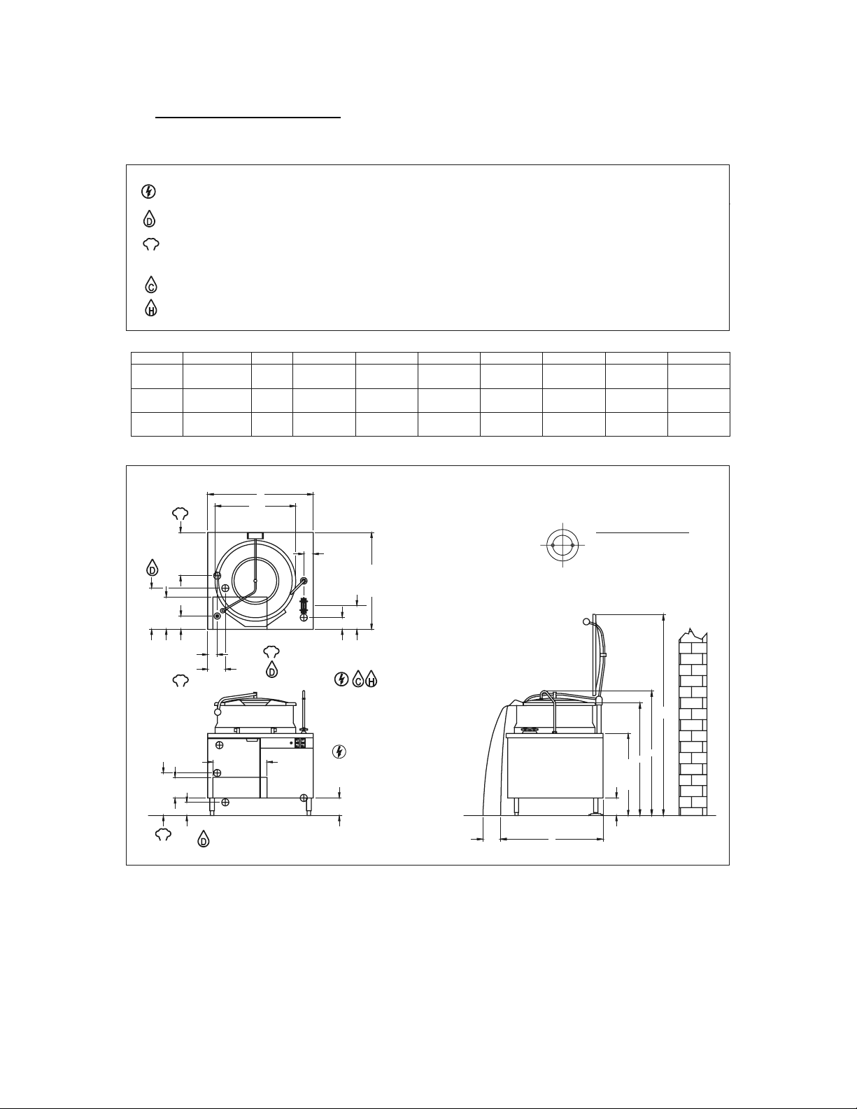
1.0 SERVICE CONNECTIONS
ELECTRICAL CONNECTION: (Tilt models only) 1/2" conduit connection to controls. Unless otherwise specified, Field Wire Electrical Connection to be 120
Volts, 60 Hertz single phase 10 Amps with grounding wire.
DRAIN: 5/8 O.D. tubing to open floor drain. No Solid Connection.
STEAM SUPPLY: 3/4" IPS for incoming steam. Min 5 PSI(34 kPa), MAX 30 PSI(207 kPa), 45 PSI (310 kPa) optional.
S
Important: Pressure reducing valve required if incoming steam pressure exceeds the kettle rating.
COLD WATER: 3/8" O.D. Tubing to faucet.
HOT WATER: 3/8" O.D. tubing to faucet.
DIMENSIONS
MODEL
KCH-30DS
KCH-40DS
KCH-60DS
CAPACITY
3O gallons
114 litres
40 gallons
151 litres
60 gallons
227 litres
S
14.75 [375]
UNITS
inches
inches
inches
B
ØA
mm
mm
mm
A
24
610
26
660
29.5
749
3.25 [83]
B
914
36
914
42
1067
DIMENSIONS ARE IN INCHES [MM].
33 [838]
C
16
406
15
381
16
406
39
991
40
1016
43
1092
D
E
37.25
946
38.38
975
41.12
1045
FLANGED FOOT DETAIL
EQUALLY SPACED
2
Ø
7/16" [11mm] HOLES
ON 2.5 [63] B.C.
41.5
1054
42.5
1080
47.62
1210
F
G
65.2536
1657
68.25
1733
74.25
1886
14 [356]
11 [279]
3.25 [83]
S
4.5 [114]
S
7 [178]
14.5 [368]
4
5
.
S
1
1
[
4
]
6 [152]
18.5 [470]
SEE NOTE
4 [102]
8 [203]
NOTE: Area for kettle draw off
must be kept free of all piping connections.
8 [203]
G
F
E
6 [152]
28 [711]
DC
4
Page 5
2.0 INSTALLATION INSTRUCTIONS
WARNING: Electrical and grounding connections must comply with
applicable portions of the National Electrical Codes.
WARNING: Plumbing connections must comply with applicable health,
safety and plumbing codes.
1. Select a location to provide drainage directly below the draw-off valve. Allow
sufficient rear clearance from the wall for the kettle cover to lift upright freely without
obstructions. Allow for clearance to side service panels.
2. Level the unit. Then mark anchoring hole locations through flanged adjustable feet.
3. With hole locations marked, drill holes and insert expansion plugs to accommodate
5/16" size lag bolts.
4. Reposition the kettle. Check the level again.
5. Bolt the kettle down and seal with a high grade sealing compound. Sealant must be
applied not only to bolt heads but around the flanges and must be making contact
with floor surface to meet N.S.F. requirements. Wipe off excess sealant
immediately.
6. Connect the steam line to the kettle (3/4" i.p.s., 5 psi minimum to 30 psi maximum, or
45 psi with optional high pressure operation).
7. If the incoming steam pressure is greater than the kettle maximum operating
pressure, then a pressure reducing valve (supplied by others) must be installed in
the line.
8. Connect hot and cold water supply to the faucet.
5
Page 6

INSTALLATION INSTRUCTIONS (Continued)
9. A control box with a power supply equivalent to electrical rating of the unit should be
located nearby. A waterproof electrical connection for the power supply to the unit
must be provided.
10. The relief valve on the kettle must not be adjusted or closed off as it is set to relieve
excess pressure in the kettle.
11. If large amounts of water accumulate in the steam line, it will be necessary to install
one or more ball float traps (supplied by others) in the line to eliminate the water.
12. A steam line pressure gauge (supplied by others) is also recommended to determine
the actual amount of steam coming to the kettle.
13. Turn unit on when electrically connected, then check for proper operation.
6
Page 7

3.0 INTRODUCTION
DESCRIPTION
The Blodgett KCH-DS kettles are direct steam tilting models mounted in a modular
cabinet base. It has a hydraulic pump and cylinder to tilt the kettle to any angle between
zero and ninety degrees for complete emptying of food products. Includes a pan carrier
that holds a 12" x 20" pan. (Pan not supplied.)
The KCH-DS are direct steam operated pressure vessels with a double wall stainless
steel construction forming a steam chamber (jacket) around the lower two thirds of the
kettle. These kettles are furnished with a steam control valve and a hot and cold water fill
faucet mounted on the stainless steel counter top. Every kettle has a pressure relief
valve. Access to the inner cabinet area for installation or service is through the
removable side panels or the doors on the front of the unit.
The kettle bowl is the container for the food product which ideally should be a liquid or
semi-liquid for complete contact with the bowl surface to fully absorb the heat
transmitted through the surface from the steam in the kettle jacket.
These kettles are intended to be permanently floor mounted with adjustable flanged feet.
7
Page 8

4.0 BASIC FUNCTIONING
1. CAPACITIES
All model names contain either a 30, 40 or 60 to indicate the capacity of that kettle in
gallons. For example, model KCH-40DS indicates a tilting two thirds jacketed steam
kettle mounted in a cabinet base, with a capacity of 40 gallons.
CONTROLS
The electric controls are in the upper right area of the kettle front. One control is an
ON-OFF switch for the tilting mechanism. The second control, in the up position tilts
the kettle forward to full tilt. In the down position the kettle is lowered to full down.
Stopping the up or down control will hold the kettle at any position the kettle is
stopped.
PAN CARRIER
The KCH-DS is equipped with a pan carrier. The pan support is made of stainless steel
and is removable, without tools, for cleaning. It holds one 12" x 20" pan and will locate
the pan in a horizontal position not more than 2" from the kettle lip throughout the tilting
operation.
SWING DRAIN
Each kettle has a swing drain to use with the draw-off valve. It is removable, without
tools, and has a removable strainer.
HYDRAULIC SYSTEM
The hydraulic system has been adjusted and tested at the factory and no further
adjustment should be needed. If the unit fails to operate properly, all service work must
be performed by a qualified service agent.
8
Page 9

5.0 OPERATING INSTRUCTIONS
WARNING: Do not tilt kettle with lid down.
WARNING: The kettle is hot. Use care when operating and servicing the kettle.
1. Turn the power switch on only during tilt cycles. Running the hydraulic power unit
continuously may overheat or damage the system.
2. Push the toggle switch to the up position. Check that the kettle begins to rise. Allow
the kettle to travel to its full up position then push the toggle switch to the down
position and the kettle will return to the original position. The kettle will stop and hold
its position at any point along the travel path if the toggle switch is released.
3. Check that the draw-off valve is closed.
4. Fill the kettle with product to the desired level.
NOTE: Food products with milk or egg base should be placed into a cold kettle before the
cooking operation begins. Avoid sudden contact of these food products in a hot kettle, the
food will stick to the surface.
5. Slowly turn the steam control valve to the full open position (counterclockwise). The
kettle will begin to heat
6. Regulate the steam control valve depending on the type of food being prepared.
7. When the food is cooked, turn off the steam, remove the food by tilting. Clean the
kettle immediately to prevent residue from drying on the kettle bowl.
9
Page 10

6.0 MAINTENANCE
KETTLE
No preventive maintenance is required other than adhering to the Cleaning Procedure
instructions.
HYDRAULIC SYSTEM
SERVICE
Set up regular schedule for checking the oil temperature, hydraulic hoses and keeping
the equipment clean. A thick layer of dirt acts as insulation and prevents the hydraulic
system from getting rid of heat.
The hydraulic system has been adjusted and tested at the factory and no further
adjustment should be needed. If the unit fails to operate properly, all service work must
be performed by a qualified service agent.
1. Hot oil in the Hydraulic System is one of the primary causes of poor operation.
When the tilt system is not in use turn MOTOR switch off.
2. Inspect hydraulic hoses for wear and aging.
3. Check that fluid levels are kept full.
4. To replace oil, fill through filler breather.
5. Use proper oil as specified by factory. TYPE: AWH32 or equivalent.
6. Check the cleanliness of the oil strainer inside the reservoir once per year. This item
can be washed in clean Varsol.
7. Change the breather filter once per year.
8. Change the oil once every two years.
10
Page 11

7.0 HYDRAULIC SYSTEM ADJUSTMENTS
There are three controls available on this power unit. The first is an adjustable relief
valve mounted into the custom aluminum manifold block. The other two control the
linear speed of the actuator.
RELIEF VALVE:
The relief valve is located underneath an aluminum hexagon cover on the side of the
custom manifold block. This relief valve is factory set to 825 P.S.I. and locked and
should not be adjusted.
If adjustments are necessary, remove the hexagon cover which will give access to the
relief valve screw. With the pump running, and with a suitable flat blade style
screwdriver, rotate the screw clockwise to increase pressure, and anti clockwise to
decrease pressure. While this operation is being carried out some oil will leak down the
threads of the adjusting screw.
To obtain the pressure required, a pressure gauge will have to be located in the circuit.
The best location is on the cylinder hose. To set the pressure, energize the solenoid to
extend the cylinder fully and thus “deadhead” the system. The pressure can be set as
indicated above. When adjustment is complete, replace the hexagon cover. This will
seal the relief valve area. The actual factory set pressure is noted on the label and
should not be exceeded as this affects the HP draw on the electric motor.
FLOW CONTROL:
There are two flow control valves mounted on the power unit and located on the solenoid
valve subplate. The flow control valves will restrict the capacity of oil passing through
them when the knurled knob is screwed in - in a clockwise direction. This action will
reduce the linear speed of the cylinder. Turning the flow control valve adjustment in the
opposite direction - anti clockwise, will increase the speed of the cylinder. One flow
control valve (right side) will allow adjustment of the extension speed (travel speed
should be set at minimum 20 seconds), the other (left side) the retraction speed.
(Retraction speed should be set at minimum 10 seconds).
IMPORTANT:
It should be noted that if the cylinder speed is restricted by the flow control valves, the
balance of oil not delivered to the cylinder will go over the relief @ 825 P.S.I. which will
cause unwanted heat in the reservoir.
11
Page 12

8.0 CLEANING INSTRUCTIONS
Your kettle should be cleaned immediately after each use when cooking a different
product or when cooking is completed. Before cleaning, check that the kettle has cooled
enough to touch it.
1. Check that the steam supply and power supply is OFF.
2. Rinse the inside of the kettle thoroughly and drain to remove any food particles.
3. Using a nylon brush, clean the kettle with a mild detergent and water. Never use
steel wool or scouring powder as it will scratch stainless steel. Plain steel wool can
leave small pieces of steel which can rust.
4. Tilt the kettle to its highest position to allow the detergent and water solution to drain.
Rinse thoroughly with clean water.
5. By hand, turn the large hex nut on the draw-off valve counterclockwise until it is
completely disengaged from the threads. Grasp the valve knob and slowly pull out
the valve stem and disk. Do not allow the disk to come in contact with hard surfaces
as it can be damaged and cause valve leakage. Wash the valve stem, disk and
handle. Brush vigorously.
6. Replace the valve stem assembly and turn the hex nut until snug. Rinse the kettle
with clean warm water.
7. Wipe the exterior of the kettle with a clean, damp cloth.
8. Never spray water into the electrical controls.
CAUTION: Do not use cleaning agents that are corrosive.
Use of cleaning agents that contain chloride, acids or salts are corrosive and may cause
pitting and corrosion when used over a period of time; this will reduce the life of the
appliance.
Should pitting or corrosion occur this is not covered by warranty.
Follow the recommended cleaning instructions. Use a mild detergent, warm water and
rinse thoroughly.
12
Page 13

8.0 CLEANING INSTRUCTIONS (Continued)
WHAT TO DO IF SURFACE RUST APPEARS
Metal utensils should never be used as they will scratch the surface of the equipment
and rust may begin to form. To remove surface accumulation of rust from the
inadvertent use of such utensils, the following procedure may be used.
WARNING: Improper use of this procedure may damage your appliance!
1. Use undiluted white vinegar with a non-abrasive scouring pad (plastic) or cloth on the
affected area to remove the rust stain. The appliance should not be heated and
remain at room temperature during the entire cleaning process.
2. If the stain resists removal, additional exposure time with vinegar may be required, to
a maximum of one hour.
3. Thoroughly wash all of the vinegar away with fresh clear water. Dry the surface
completely and allow one hour before using the appliance to cook.
9.0 TROUBLESHOOTING
EXTREMELY SLOW COOKING TIME
Abnormally slow cooking time may be due to insufficient steam pressure and/or volume.
Inlet pressures of less than 10 psi will result in slow cooking performance. Note that
pressures approaching the rated kettle pressure are liable to set off the safety relief
valve. If required pressure is not available to kettle, then volume of steam is not
sufficient. Minimum 3/4" pipe size is required to the kettle, but if the steam generating
source is at a great distance from the kettle, larger pipe will be required. Also check the
core of the steam supply pipe for debris or scalants that impede steam flow. May
require disassembly and inspection.
DRAW OFF VALVE LEAKS
If a leak occurs through the valve stem, replace the “O” ring. If the leak can be attributed
to faulty sealing occurring between the stem disc and valve seat, then quite often this
problem can be corrected by cleaning off the dried on food residue with an extremely
fine emery cloth. If not, the rubber vulcanized stem piece has been damaged and must
be replaced.
NOTICE: DRAW OFF VALVE HAS A VULCANIZED RUBBER COATED STEM FOR BETTER
SEALING. DO NOT OVER TIGHTEN. THIS MAY CAUSE THE RUBBER TO PULL AWAY FROM
STEM AND PERMANENTLY DAMAGE IT.
13
Page 14

HOUGHTON CANADA INC.
100 Symes Road, P.O. Box 113, Station D
Toronto, Ontario, Canada, M6P 3J5
MATERIAL SAFETY DATA SHEET
Review Date: October 22, 2002
Product Code: 07122016
COSMOLUBRIC HF 122
SECTION I - PRODUCT IDENTIFICATION
Proper Shipping Name: Hydraulic System Fluid, Other Than Petroleum
WHMIS Hazard: Not Controlled
TDG Hazard Class: Non-Hazardous
Hazard Number: Not applicable
Chemical Family: Mixture
Completed By: J. Pajak
Telephone Number: 1-416-763-4691
Facsimile Number: 1-416-763-3167
DUNS Number: 20-167-2573
SECTION II - HAZARDOUS COMPONENTS
Material Description CAS No. Percent Hazard
This product contains no known hazardous components under current OSHA, ACGIH,
WHMIS or the IDL regulations.
SECTION III - PHYSICAL DATA
Boiling Point (Degree Fahrenheit) : >300
Specific Gravity (Water = 1) : 0.91
Vapour Pressure (mmHg) : <1
Evaporation Rate (BuAcr = 1) : <1
Vapour Density (Air = 1) : >1
Percent Volatile : Nil
Soluble in Water : Insoluble
pH Neat : Not Applicable
Appearance and Odour : Slightly hazy amber liquid with a bland odour.
14
Page 15

SECTION IV - FIRE AND EXPLOSION HAZARD DATA
Flash Point (Degrees Fahrenheit) : 520
Method Used : C.O.C.
LEL : Not Determined
UEL : Not Determined
NFPA Classifications, Health : 1
Fire : 1
Reactivity : 0
Extinguishing Methods : Carbon dioxide, foam, dry chemical
Special Fire Fighting Instructions : None required
Unusual Fire and Explosion Hazards: None
SECTION V - HEALTH HAZARD INFORMATION
Threshold Limit Value (TLV) and Permissible Exposure Limit (PEL): See Section II Hazardous Components
Primary Routes of Exposure - Eyes, skin, inhalation.
Chronic or Recurrent Effects: Unknown for this product.
Acute Effects:
Inhalation: No significant effects known.
Skin: May be a mild irritant on prolonged contact.
Eyes: Mild irritant
Ingestion: No significant effects known.
*** First Aid ***
Inhalation: Not applicable.
Skin: Wash with soap and water. Remove contaminated clothing and launder before
reusing.
Eye: Flush with water for 15 minutes. Consult physician.
Ingestion: Induce vomiting. Give liquids. Consult physician. Product contains fatty
acid ester.
Note to Physicians: No specific antidote known. Based on individual reactions of the
patient, the physician’s judgement should be used to control symptoms and clinical
conditions.
15
Page 16

SECTION VI - REACTIVITY DATA
Stability: Stable [X], Unstable [ ]
Incompatibility (Materials to Avoid): Strong Oxidizers
Hazardous Decompostion Products: Thermal, Oxides of Carbon
Hazardous Polymerization: May Occur: [ ], Will Not Occur [X]
SECTION VII - SPILL OR LEAK PROCEDURES
Potential as a Pollutant: Not considered a pollutant if effective waste disposal methods
are utilized. Keep out of sewers and streams.
Spill, Leak or Release: Apply dry absorbent material and sweep up.
Waste Disposal: Follow pertinent regulations for disposal. It is the responsibility of the
product user to determine, at the time of disposal, whether a material containing the
product or derived from the product should be classified as a hazardous waste (40 CFR
261.20-24).
SECTION VIII - SPECIAL PROTECTION INFORMATION
Respiratory Protection: Not required.
Ventilation: General workplace ventilation is satisfactory
Protective Gloves: Rubber if skin is sensitive.
Eye Protection: Safety goggles or safety glasses with side shields.
Other Protective Equipment: Eye wash and safety shower recommended.
SECTION IX - SPECIAL PRECAUTIONS
Storage and Handling: Keep containers closed when not in use. Avoid contact with
strong oxidizers. Wash thoroughly after handling.
16
Page 17

ADDITIONAL PRODUCT INFORMATION
Carcinogens as Defined By: NTP: None
IARC: None
OSHA: None
Cercla Reportable Quantity (Ibs.): None
RCRA Hazardous Waste Number: Not Applicable
CEPA: All components of this product are listed on the Domestic Substances List (DSL)
as encoded in the extract of the Canada Gazette, Part I.
SARA, Title III, Section 313: This product contains no toxic chemicals subject to the
reporting requirements of Section 313 of Title III of the Superfund Amendments and
Reauthorization Act of 1986 and 40 CFR part 372.
The information contained herein is based on data considered accurate. However, no
warranty is expressed or implied regarding the accuracy or the translation of this data or
the results to be obtained from the use thereof. Houghton Canada Inc. assumes no
responsibility for personal injury or damage to users or third parties caused by the
material. Such users assume all risks associated with the use of the material.
17
 Loading...