

Page 1

CB-E SERIES
ELECTRIC STEAM BOILER CABINETS
INSTALLATION – OPERATION – MAINTENANCE
BLODGETT OVEN COMPANY
www.blodgett.com
44 Lakeside Avenue, Burlington, Vermont 05401 USA Telephone (800) 331-5842, (802) 860-3700 Fax: (802) 864-0183
S00045 Rev A (5/04)
1
Page 2
IMPORTANT NOTES FOR INSTALLATION AND OPERATION
It is recommended that this manual be read thoroughly and that all instructions be
followed carefully.
This is the safety alert symbol. It is used to alert you to
potential personal injury hazards. Obey all safety messages
that follow this symbol to avoid possible injury or death.
WARNING: Improper installation, operation, adjustment,
alteration, service or maintenance can cause property damage,
injury or death. Read the installation, operating and
maintenance instructions thoroughly before installing,
operating or servicing this equipment.
CAUTION: Operating, testing, and servicing should only be
performed by qualified personnel.
WARNING: Disconnect the power supply to the appliance
before cleaning or servicing.
Intended for commercial use only. Not for household use.
This manual should be retained for future reference.
2
Page 3

. TABLE OF CONTENTS
DESCRIPTION PAGE
1.0 Service Connections ................................................................................................ 4
2.0 Installation Instructions ............................................................................................. 5
3.0 Operating Instructions ..............................................................................................8
4.0 CSD-1 Optional Feature ......................................................................................... 10
5.0 Periodic Maintenance ............................................................................................. 11
6.0 Troubleshooting .....................................................................................................14
3
Page 4
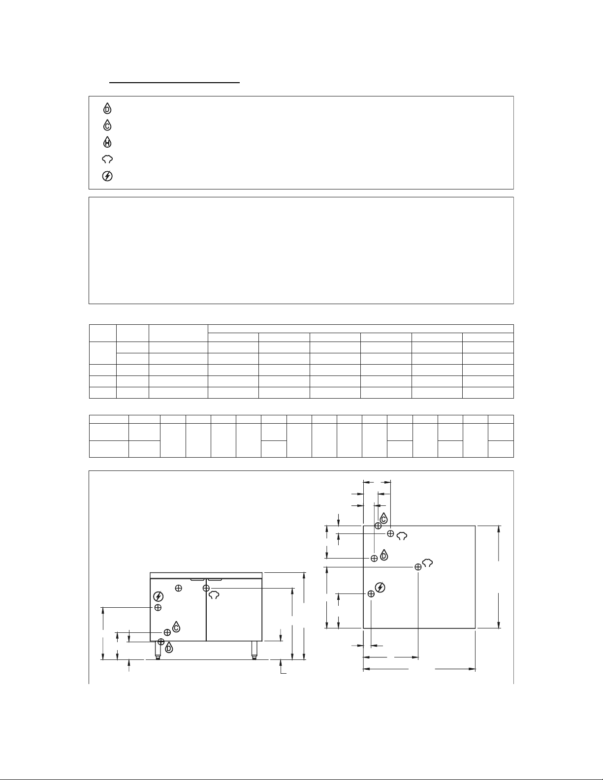
2.0 SERVICE CONNECTIONS
DRAIN: 2"IPS piped to open floor drain. No Solid Connection.
COLD WATER: 3/8" O.D. tubing at 25-50 PSI(170-345 kPa)
HOT WATER: 3/8" O.D. tubing at 25-50 PSI(170-345 kPa)
S
STEAM TAKE-OFF CONNECTION: 3/4"IPS to operate adjacent equipment.
Field Wiring Electrical Connection to be as specified on data plate.
Water quality is the major factor affecting the performance of your appliance. If you are unsure of water quality, consult a
local water treatment specialist and have the water analyzed. Your water supply must be within these general guidelines:
Water which fails to meet these standards should be treated by installation of a water conditioner.
FAILURE OR MALFUNCTION OF THIS APPLIANCE DUE TO POOR WATER QUALITY IS NOT COVERED UNDER WARRANTY.
kW
24
36
42
WIDTH
24
610
36
914
PHASE
1
3 69 66.6 62.9 57.7 36.5 33.4 28.9
3
314848
UNITS
OUTPUT
MAX. LBS/HR.
69
107
128
BCD
inches
mm 70
inches
mm 540
8.75
A
5.75
146222
208V
115 .4
99.9
116 .63
N/A N/A
16.75
425
WATER QUALITY STATEMENT
Total dissolved solids
Total alkalinity
Silica
Chlorine
pH Factor
Less than 60 PPM
Less than 20 PPM
Less than 13 PPM
Less than 1.5 PPM
7.0-8.5
ELECTRICAL CHARACTERISTICS
94.5
AMPS PER LINE
240V
100.0
86.6
115.5 72.9 66.8 57.7
220V
109.1
110.2 101.0
DIMENSIONS
23
584
EF
8.75
222
18
457
3.5
G
H
10.5
267
2.5
64
89
11. 12
283
N
19.75
502
480V
N/A
43.3
50.5
4.75
121
6.75
171
380V
N/A
54.7
J
K
2.75
4.75
121
415V
N/A
50.1
58.463.8
L
MP
13
330
2.5
64
21.25
DIMENSIONS ARE IN INCHES [MM]
NOTE: PRESSURE REDUCING VALVE -OPTIONAL
S
C
A
B
D
6 [152]
E
K
F
H
G
N
J
28 [710]
L
S
S
33 [838]
M
WIDTH
24 [610] or 36 [914]
4
Page 5

2.0 INSTALLATION INSTRUCTIONS
GENERAL
The electric boiler is designed to ASME Code and approved as a steam heating boiler
restricted to operation at pressure not to exceed 15 psi. Boilers are electrically rated as
shown on page 4. Boiler may have optional CSD1 controls.
UNPACKING
Immediately after unpacking, check for possible shipping damage. If the appliance is
found to be damaged, save the packaging material and contact the carrier within 15
days of delivery. Before installing, verify the electrical rating agrees with the
specification on the rating plate.
LOCATION
Position the boiler in its installation location. Check that there are sufficient clearances
to service the controls, door swing, etc. Also adequate clearance must be left for making
the required supply and drain connections.
Allow enough space between any other piece of equipment or wall for service access.
Service to the controls may be required on the left and/or right side panels of the
cabinet.
INSTALLATION CODES AND STANDARDS
The boiler must be installed in accordance with:
In Canada:
Provincial and local codes, or in the absence of local codes, with the Canadian Electric
Code, CSA C22.1 (latest edition). Copies may be obtained from the Canadian
Standards Association, 178 Rexdale Blvd., Etobicoke, Ontario, Canada, M9W 1R3.
In the U.S.A.:
State and local codes, or in the absence of local codes, with the National Electrical
Code, ANSI/NFPA-70 (latest edition). Copies may be obtained from The National Fire
Protection Association, Batterymarch Park, Quincy, MA, 02269.
5
Page 6
LEVELING AND ANCHORING THE CABINET
1. Place appliance in the installation position.
2. Place a carpenter’s level on top of the appliance and turn the adjustable feet to level
side-to-side and front-to-back.
3. Mark hole locations on the floor through the anchoring holes provided in the rear
flanged adjustable feet.
4. Remove appliance from installation position and drill holes in locations marked on
the floor. (See installation diagram on page 4.) Insert proper anchoring devices (not
supplied).
5. Place appliance back in the installation position.
6. Place carpenter’s level on top of appliance and re-level side-to-side and front-toback.
7. Bolt and anchor appliance securely to the floor.
8. Seal bolts and flanged feet with silastic or equivalent compound.
ELECTRICAL CONNECTIONS
WARNING: Electrical and grounding connections must comply with the
applicable portions of the National Electrical Code and/or other local
electrical codes.
WARNING: Disconnect electrical power supply and place a tag at the
disconnect switch to indicate you are working on the circuit.
When making electrical connections, use copper wire suitable for at least 200EF (90EC).
The steamer must be grounded in accordance with the National Electrical Code or
applicable local codes. The wiring diagram is located on the inside of the right panel.
6
Page 7

EXHAUST HOOD
An exhaust system should be located directly above the boiler to exhaust steam and
heat generated by the boiler.
PLUMBING CONNECTIONS (See Page 4)
WARNING: Plumbing connections must comply with applicable sanitary,
safety, and plumbing codes.
Water Supply Connection
The incoming cold water supply connection, at the rear of the boiler cabinet, requires
3/8" tubing and water pressure of 25 - 50 psig. A manual shut-off valve must be
provided convenient to the boiler; this valve should be open when the boiler is in
operation.
Drain Connection
The boiler drain (2" IPS) should be piped to a floor drain near the boiler. There should
be no solid drain connection; an “open gap” between the boiler and the floor drain is
required.
7
Page 8

3.0 OPERATING INSTRUCTIONS
For CSD-1 equipped boilers, see section 4.0 CSD-1 Optional Feature for proper
operating instructions.
BOILER CONTROLS (Inside Cabinet)
Main Power Switch - ON fills the boiler tank and turns the boiler heaters on. You
should allow 20 minutes to fill the tank and generate steam.
- OFF shuts off the boiler heaters and opens the Automatic
Blowdown Valve, emptying the boiler tank and releasing
water and steam to the drain. This should be done daily to
remove sediment, lime, or scale.
Pilot Light - Indicates main power is ON.
Boiler Pressure Gauge - Should read 9 - 11 psig during operation; 0 psig during
shutdown.
Water Level Sight Glass - Observe level of water and water quality in the boiler.
Murkiness in the water indicates inadequate water quality;
the owner must supply proper water to the boiler (see page
4).
Water Level Control - While boiler is ON, briefly open the water level control valve
once a day to remove any sediment that might accumulate.
(See page 11 for detailed instructions.)
Safety Valve - This valve will release (pop off) if the boiler has too much
pressure. Once a week, this valve should be tripped during
operation to make sure it functions properly.
OPERATION OF THE BOILER
Turn on water and power supply.
Open cabinet door and turn main power switch ON. Pilot light ignites and water begins
to fill boiler - observe water gauge sight glass to verify that proper water level is reached.
Once the proper water level is reached, the heaters begin to heat the water. Heaters
require about 15 minutes to begin steam generation. The boiler pressure gauge in the
cabinet should indicate steam pressure in a range of 9 to 11 psig.
SHUT DOWN
Turn the Main Power Switch OFF: Open manual drain valve. If unit is supplied with
Automatic Blowdown Valve, it will open, draining the boiler and releasing hot water and
steam to the drain.
8
Page 9

4.0 CSD-1 OPTIONAL FEATURE
OPERATING, TESTING, SERVICING AND CLEANING INSTRUCTIONS
Start-up Procedure
1. Close the manual blowdown valve.
2. Open cabinet door and turn “ON” power switch.
The green pilot light will come “ON.” Water will begin to enter the boiler. When
enough water has entered the boiler, the (amber) “STANDBY” pilot light will come
on.
1. Press the “RESET” switch to begin boiler operation.
The “STANDBY” pilot light will go off and the boiler will begin operation.
Normal Boiler Operating Cycle
Water Fill Cycle
On the initial filling of the boiler, the reset switch must be activated to initialize the safety
lockout circuit. Once the water in the boiler has reached the proper level, the level
control will stop the flow of water to the boiler. As water is consumed in the production
of steam, the level control will supply additional water to the boiler.
Firing Cycle
The elements are operated by pressure sensing devices. On initial operation, the boiler
should reach 14 psi in approximately 15 minutes. At this point, the operating pressure
switch will open, de-energizing the elements. Thereafter the operating pressure switch
will cycle the elements between 9 and 11 psi boiler pressure.
Condensing Drain
A thermostat is located in the drain assembly and is activated by the temperature of
steam. The thermostat operates the cooling solenoid, supplying water to the drain to
condense the steam.
Automatic Blowdown Valve
If the unit has an automatic blowdown valve, it is activated when the main power switch
is activated. The boiler will be drained should the main power switch be turned “OFF.”
9
Page 10

SAFETY LOCKOUT CONDITIONS
High Temperature Condition
A high temperature safety device is installed on the boiler. Should the temperature
exceed the limit of this device, the boiler will be shut down and put in a state of lockout.
The “TEMPERATURE” pilot light (red), and the “STANDBY” pilot light (amber), will come
on.
High Pressure Condition
A high pressure safety switch is installed on the boiler. Should the pressure exceed the
limit of this device, the boiler will be shut down and put into a state of lockout. The
“PRESSURE” pilot light (red), and the “STANDBY” pilot light (amber), will come on.
Should this device fail to operate, the safety relief valve will open.
Low Water Condition
A second low water safety cut off is supplied with the boiler. Should the water level fall
below normal operating levels, the boiler will be shut down and put into a state of
lockout. The “LOW WATER” pilot light (red), and the “STANDBY” pilot light (amber) will
come on.
10
Page 11

5.0 PERIODIC MAINTENANCE
Be sure to flush your boiler water level control daily. Failure to follow this procedure can
cause the control to malfunction resulting in serious boiler damage.
The Boiler Water Level Control installed on your boiler requires periodic maintenance.
As boiler water circulates into the float chamber, sand, scale and other sediment may be
deposited in the float chamber. While the chamber has been designed with a large
accumulation bowl, it is necessary to flush the sediment from the chamber by blowing
down the control so that the accumulation of sediment does not interfere with the
movement of the float in the control. Control must be flushed at least once a day.
CAUTION: Protect yourself. When flushing control, hot water and steam
will flow out of the drain.
When flushing control, note water level in gauge glass, allow the boiler to fill if
necessary, and also to come up to temperature.
Before flushing control, note that water level in gauge glass is within operating range and
the boiler pressure is at least 6 psi. While the boiler is being fired, open blowdown valve
at bottom of control by rotating the handle counterclockwise about 1/4 turn to fully open
the valve. Opening the blowdown valve also checks the cut-off operation. Float should
drop shutting elements off, hot water and steam will flow out the drain flushing away
sediment.
CAUTION: If heater does not shut off during blowdown, immediately
discontinue use of appliance and call for service.
11
Page 12

PERIODIC MAINTENANCE (Continued)
Continue draining water for about fifteen (15) seconds, from control until water is clean.
Manually close valve. Recheck gauge glass. If water level has dropped significantly,
wait for the boiler to restore water level and pressure and repeat if necessary.
1. Observe that the water in gauge glass is clean and clear. Extreme murkiness in
water indicates inadequate water quality.
2. Safety valve should be tripped during operation once a week to assure that it
functions properly.
3. Keep all exposed cleanable areas of unit clean at all times.
CAUTION: Take extra caution when blowing down water level control or tripping
safety valve as extreme hot water and live steam are present.
DESCALING BOILER
It is recommended that the boiler be checked every 90 to 120 days for scale build up.
Regular maintenance should be carried out at this time.
1. With boiler empty, close manual blowdown valve. If appliance is equipped with
Automatic Blowdown, turn water supply to appliance OFF. Turn power switch ON.
This will energize and close blowdown valve.
2. Remove 3/4" pipe plug from fitting on left front of boiler.
3. Insert appropriate hose or tube through fitting and pour in (½) half gallon (U.S.) of
CLR Descaling Solution. If available, use the Optional Deliming assembly available
from your dealer.
4. Replace 3/4" pipe plug securely.
5. Open water supply to appliance allowing water to fill boiler to required level.
6. Let appliance cycle, allow two hours for descaling and cleaning. DO NOT TURN ON
STEAM to attached appliances or to upper compartment.
7. Open both the blowdown and low water level control valves for complete drainage.
After boiler drains, close both valves.
8. Turn appliance switch ON. When boiler is completely filled turn power switch OFF.
This will rinse and drain boiler. Appliances with manual blowdown valve must be
opened to drain.
9. Complete Step 8 twice to assure boiler is completely rinsed.
10. Appliance is now ready for use.
12
Page 13

6.0 TROUBLESHOOTING
At least twice a year have an authorized service person clean and adjust
the unit for maximum performance.
Water not being supplied to boiler
1. Water supply is “OFF”.
2. Defective water fill solenoid.
3. Water level control clogged or defective, unable to operate fill valve.
4. Check drain valve is closed.
5. Supply water pressure too low.
Automatic blowdown valve does not drain
1. Defective blowdown valve.
2. Heat exchanger build up of scalant clogging drain lines and valve.
Boiler achieves pressure slower than normal
1. Heavy build up of lime on elements.
2. Loose element connections.
Safety valve blows
1. Defective safety valve.
2. Pressure too high, pressure switch requires adjustment (lower) or may be defective.
13
 Loading...