

Page 1

DIRECT STEAM KETTLES MOUNTED ON
ELECTRIC STEAM BOILER CABINETS
INSTALLATION – OPERATION – MAINTENANCE
BLODGETT OVEN COMPANY
www.blodgett.com
44 Lakeside Avenue, Burlington, Vermont 05401 USA Telephone: (802) 658-6600 Fax: (802) 864-0183
S00092 Rev A (8/05)
1
Page 2
IMPORTANT NOTES FOR INSTALLATION AND OPERATION
This is the safety alert symbol. It is used to alert you to
potential personal injury hazards. Obey all safety messages
that follow this symbol to avoid possible injury or death.
WARNING: Improper installation, operation, adjustment,
alteration, service or maintenance can cause property damage,
injury or death. Read the installation, operating and
maintenance instructions thoroughly before installing,
operating or servicing this equipment.
CAUTION: Operating, testing, and servicing should only be
performed by qualified personnel.
WARNING: Disconnect the power supply to the appliance
before cleaning or servicing.
Intended for commercial use only. Not for household use.
This manual should be retained for future reference.
It is recommended that this manual be read thoroughly and that all instructions be
followed carefully.
2
Page 3

TABLE OF CONTENTS
DESCRIPTION PAGE
1.0 Service Connections .......................................................................................... 4
2.0 Installation Instructions ...................................................................................... 8
3.0 Operating Instructions ...................................................................................... 11
4.0 CSD-1 Optional Feature .................................................................................. 12
5.0 Periodic Maintenance ...................................................................................... 14
6.0 Troubleshooting ............................................................................................... 18
7.0 Introduction - Direct Steam Kettles .................................................................. 19
8.0 Operating Procedures ...................................................................................... 20
9.0 Cleaning Procedures ....................................................................................... 20
10.0 Preventive Maintenance .................................................................................. 21
3
Page 4
1.0 SERVICE CONNECTIONS
WATER QUALITY STATEMENT
Water quality is the major factor affecting the performance of your appliance. If you are unsure of water quality, consult a
local water treatment specialist and have the water analyzed. Your water supply must be within these general guidelines:
Total dissolved solids
Total alkalinity
Silica
Chlorine
pH Factor
Water which fails to meet these standards should be treated by installation of a water conditioner.
FAILURE OR MALFUNCTION OF THIS APPLIANCE DUE TO POOR WATER QUALITY IS NOT COVERED UNDER WARRANTY.
Less than 60 PPM
Less than 20 PPM
Less than 13 PPM
Less than 1.5 PPM
7.0-8.5
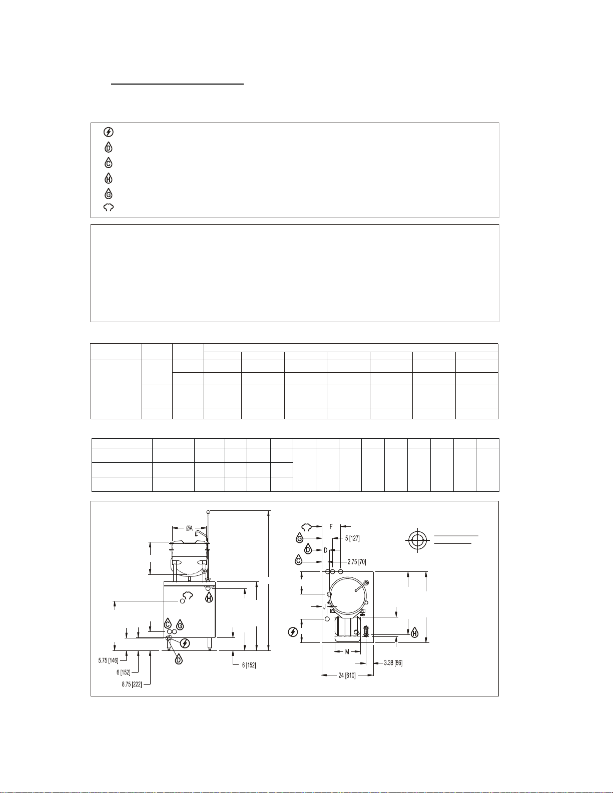
DIMENSIONS
A B
C
D E F
G
H
J
K L M
MODEL CAPACITY UNITS
CB24E-6K
CB24E-10K
CB24E-12K
6 gallons
23 litres
10 gallons
38 litres
12 gallons
45 litres
inches
mm
inches
mm
inches
mm
12
305
16
406
16
406
14.5
368
15
381
17
432
66.13
1680
65.13
1654
67.13
1705
3.58910.5
267
8.75
222
5.5
1407178
2.56411.12
283922912305
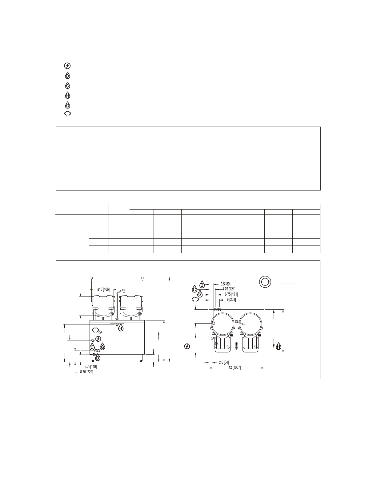
NOTE: SPLASH GUARD NOT SHOWN ON FRONT VIEW
DIMENSIONS ARE IN INCHES [MM]
REAR FLANGED
FOOT DETAIL
7/16" [11mm] HOLES
ON 2.5 [63] B.C.
2 EQUALLY SPACED
Ø
S
Field wire electrical connection to be as specified on rating plate
STEAM TAKE-OFF CONNECTION: 3/4"IPS to operate adjacent equipment.
COLD WATER: condensing drain and water faucet, 3/8" O.D. tubing at 25-50 PSI(170-345 kPa)
DRAIN: 2"IPS piped to open floor drain. No Solid Connection.
HOT WATER: 3/8" O.D. tubing at 25-50 PSI(170-345 kPa)
GENERATOR WATER: 3/8" O.D. tubing at 25-50 PSI(170-345 kPa)
ELECTRICAL CHARACTERISTICS
99.9
116.6
3
3
PHASE
208V
110.2 101.0
220V
94.5
240V
AMPS PER LINE
86.6
480V
58.463.8
415V
54.7
380V
50.1
50.5
43.3
24
42
36
kW
3
48
N/A
N/A
115.5 72.9 66.8 57.7
3 66.6 63
57.7
36.5 33.4 28.9
600V
40.5
34.6
46.2
23.1
MODEL
CB24E-6K
CB24E-10K
CB24E-12K
1 115.4 109.1
100
N/A N/A N/A N/A
S
B
23 [584]
32 [813]
C
28.87 [733]
S
33 [838]
L
E
K
29.25 [743]
Models CB24E-6K, CB24E-10K and CB24E-12K
4
Page 5
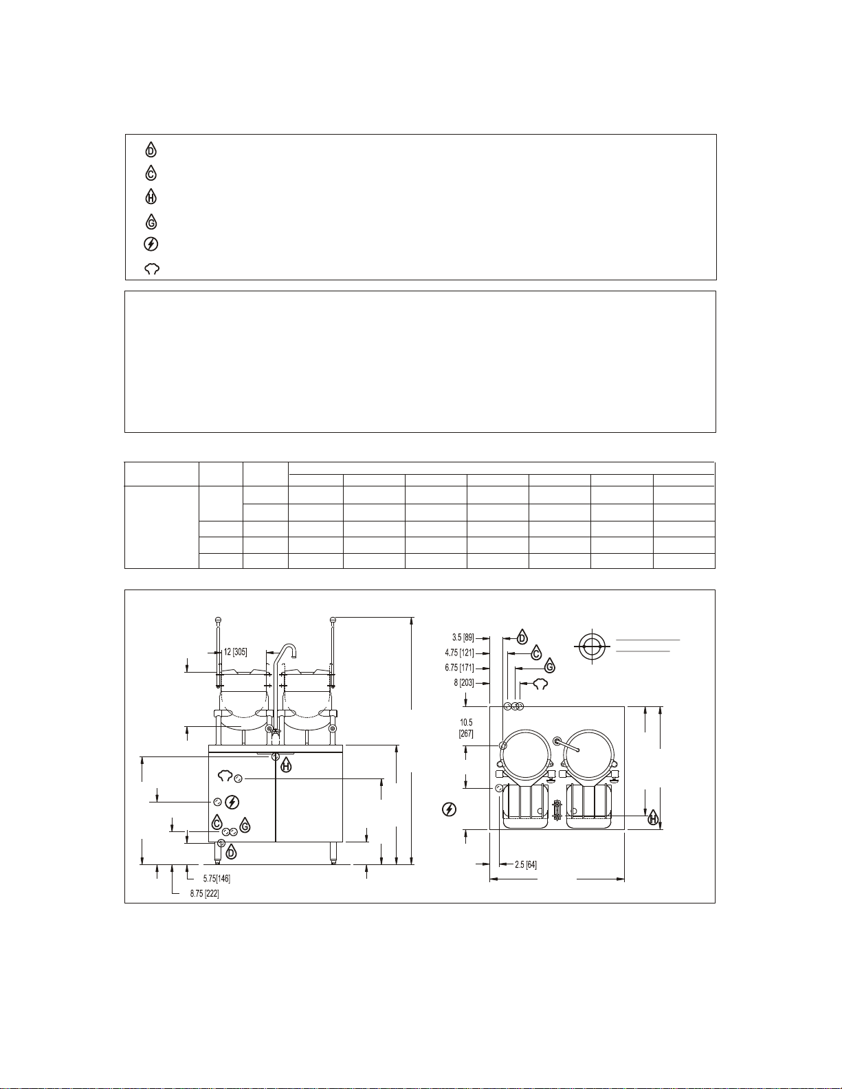
Model CB36E-6-6K
WATER QUALITY STATEMENT
Water quality is the major factor affecting the performance of your appliance. If you are unsure of water quality, consult a
local water treatment specialist and have the water analyzed. Your water supply must be within these general guidelines:
Total dissolved solids
Total alkalinity
Silica
Chlorine
pH Factor
Water which fails to meet these standards should be treated by installation of a water conditioner.
FAILURE OR MALFUNCTION OF THIS APPLIANCE DUE TO POOR WATER QUALITY IS NOT COVERED UNDER WARRANTY.
Less than 60 PPM
Less than 20 PPM
Less than 13 PPM
Less than 1.5 PPM
7.0-8.5
NOTE: SPLASH GUARD NOT SHOWN ON FRONT VIEW
DIMENSIONS ARE IN INCHES [MM]
REAR FLANGED
FOOT DETAIL
7/16" [11mm] HOLES
ON 2.5 [63] B.C.
2 EQUALLY SPACED
Ø
S
Unless otherwise specified, field wire electrical connection to be 208, 220 or 240 volts, 3 phase, 60 Hz with grounding wire.
STEAM TAKE-OFF CONNECTION: 3/4"IPS to operate adjacent equipment.
COLD WATER: condensing drain and water faucet, 3/8" O.D. tubing at 25-50 PSI(170-345 kPa)
DRAIN: 2"IPS piped to open floor drain. No Solid Connection.
HOT WATER: 3/8" O.D. tubing at 25-50 PSI(170-345 kPa)
GENERATOR WATER: 3/8" O.D. tubing at 25-50 PSI(170-345 kPa)
ELECTRICAL CHARACTERISTICS
99.9
116.6
3
3
PHASE
208V
110.2 101
220V
94.5
240V
AMPS PER LINE
86.6
480V
58.463.8
415V
54.7
380V
50.1
50.5
43.3
24
42
36
kW
3
48
N/A
N/A
115.5 72.9 66.8 57.7
3
66.6 63 57.7 36.5 33.4 28.9
600V
40.5
34.6
46.2
23.1
MODEL
CB36E-6-6K
1
115.4 109.1 100 N/A N/A N/A N/A
16.75 [425]
6 [152]
32 [813]
23 [584]
14.5 [368]
66.13 [1680]
28.88 [733]
S
11.12
[283]
29.25 [743]
S
33 [838]
36 [914]
5
Page 6
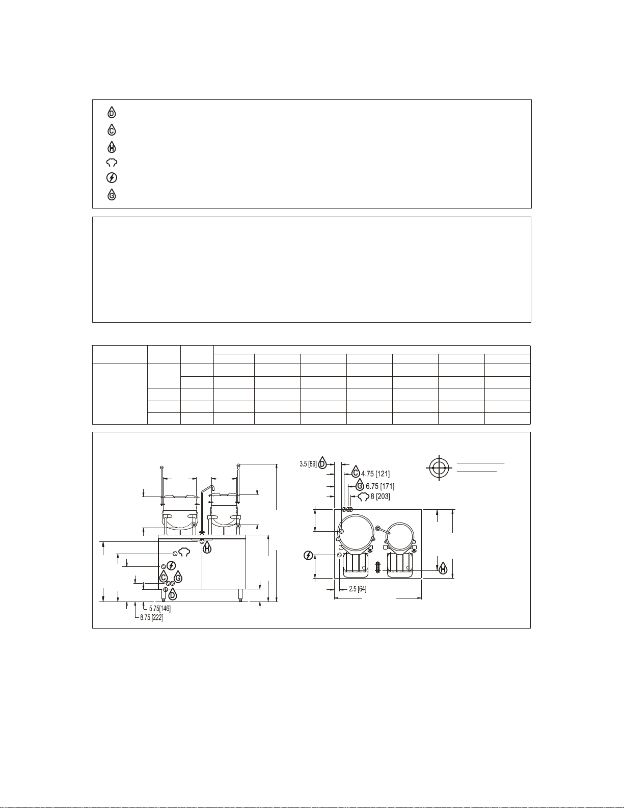
Model CB42E-10-6K
WATER QUALITY STATEMENT
Water quality is the major factor affecting the performance of your appliance. If you are unsure of water quality, consult a
local water treatment specialist and have the water analyzed. Your water supply must be within these general guidelines:
Total dissolved solids
Total alkalinity
Silica
Chlorine
pH Factor
Water which fails to meet these standards should be treated by installation of a water conditioner.
FAILURE OR MALFUNCTION OF THIS APPLIANCE DUE TO POOR WATER QUALITY IS NOT COVERED UNDER WARRANTY.
Less than 60 PPM
Less than 20 PPM
Less than 13 PPM
Less than 1.5 PPM
7.0-8.5
NOTE: SPLASH GUARD NOT SHOWN ON FRONT VIEW
DIMENSIONS ARE IN INCHES [MM]
REAR FLANGED
FOOT DETAIL
7/16" [11mm] HOLES
ON 2.5 [63] B.C.
2 EQUALLY SPACED
Ø
16.75 [425]
15 [381]
32 [813]
6 [152]
23 [584]
Ø16
[406]
14.5 [368]
Ø12
[305]
66.13 [1680]
S
28.88 [733]
11.12 [283]
42 [1067]
29.25 [743]
10.5 [267]
S
33 [838]
S
FIELD WIRE ELECTRICAL CONNECTION to be specified on data plate
STEAM TAKE-OFF CONNECTION: 3/4” IPS optional to operate adjacent equipment
.COLD WATER: condensing drain and water faucet, 3/8” O.D. tubing at 25-50 PSI (170-345 kPa)
DRAIN: 2"IPS piped to open floor drain. No Solid Connection.
HOT WATER: water faucet, 3/8” O.D. tubing at 25-50 PSI (170-345 kPa)
GENERATOR WATER: 3/8” O.D. tubing at 25-50 PSI (170-345 kPa).
ELECTRICAL CHARACTERISTICS
99.9
116.6
3
3
PHASE
208V
110.2 101.0
220V
94.5
240V
AMPS PER LINE
86.6
480V
58.463.8
415V
54.7
380V
50.1
50.5
43.3
24
42
36
kW
3
48
N/A
N/A
115.5 72.9 66.8 57.7
3 66.6 63 57.7 36.5 33.4 28.9
600V
40.5
34.6
46.2
23.1
MODEL
CB42E-10-6K
1 115.4 109.1 100 N/A N/A N/A N/A
6
Page 7
Model CB42E-10-10K
WATER QUALITY STATEMENT
Water quality is the major factor affecting the performance of your appliance. If you are unsure of water quality, consult a
local water treatment specialist and have the water analyzed. Your water supply must be within these general guidelines:
Total dissolved solids
Total alkalinity
Silica
Chlorine
pH Factor
Water which fails to meet these standards should be treated by installation of a water conditioner.
FAILURE OR MALFUNCTION OF THIS APPLIANCE DUE TO POOR WATER QUALITY IS NOT COVERED UNDER WARRANTY.
Less than 60 PPM
Less than 20 PPM
Less than 13 PPM
Less than 1.5 PPM
7.0-8.5
NOTE: SPLASH GUARD NOT SHOWN ON FRONT VIEW
DIMENSIONS ARE IN INCHES [MM]
REAR FLANGED
FOOT DETAIL
7/16" [11mm] HOLES
ON 2.5 [63] B.C.
2 EQUALLY SPACED
Ø
S
Field Wire Electrical Connection to be as specified on rating plate.
STEAM TAKE-OFF CONNECTION: 3/4” IPS optional to operate adjacent equipment
COLD WATER: condensing drain and water faucet, 3/8” O.D. tubing at 25-50 PSI (170-345 kPa)
DRAIN: 2"IPS piped to open floor drain. No Solid Connection.
HOT WATER: 3/8” O.D. tubing at 25-50 PSI (170-345 kPa)
GENERATOR WATER: 3/8” O.D. tubing at 25-50 PSI (170-345 kPa)
ELECTRICAL CHARACTERISTICS
99.9
116.6
3
3
PHASE
208V
110.2 101.0
220V
94.5
240V
AMPS PER LINE
86.6
480V
58.463.8
415V
54.7
380V
50.1
50.5
43.3
24
42
36
kW
3
48
N/A
N/A
115.5 72.9 66.8 57.7
3 66.6 63
57.7
36.5 33.4 28.9
600V
40.5
34.6
46.2
23.1
MODEL
CB42E-10-10K
1 115.4 109.1
100
N/A N/A N/A N/A
S
16.75 [425]
23 [584]
6 [152]
32 [813]
15 [381]
65.13 [1654]
28.88 [733]
29.25 [743]
S
10.5
[267]
11.12
[283]
33 [838]
7
Page 8

2.0 INSTALLATION INSTRUCTIONS
GENERAL
Direct steam tilting kettle(s) mounted on a cabinet base, housing an ASME Code
designed electric steam boiler approved as a steam boiler restricted to operation at
pressure not to exceed 15 psi. Hot and cold water fill faucet, 5" (152 mm) deep sink with
drain and splash guard(s). All models are suffixed with either -6, -10 or -12 to indicate
the capacity of the kettle(s) in US gallons. The electric boiler may be rated at 24 kW, 36
kW, 42 kW or 48 kW. Operational on 208V, 220V, 240V, 380V, 415V or 480V and have
optional CSD1 controls.
INSTALLATION
UNPACKING
Immediately after unpacking, check for possible shipping damage. If the appliance is
found to be damaged, save the packaging material and contact the carrier within 15
days of delivery. Before installing, verify the electrical rating agrees with the
specification on the rating plate.
LOCATION
Position the boiler in its installation location. Check that there are sufficient clearances
to service the controls, door swing, etc. Also adequate clearance must be left for making
the required supply and drain connections.
Allow enough space between any other piece of equipment or wall for service access.
Service to the controls may be required on the left and/or right side panels of the
cabinet.
INSTALLATION CODES AND STANDARDS
The boiler must be installed in accordance with:
In Canada:
Provincial and local codes, or in the absence of local codes, with the Canadian Electric
Code, CSA C22.1 (latest edition). Copies may be obtained from the Canadian
Standards Association, 178 Rexdale Blvd., Toronto, Ontario, Canada, M9W 1R3.
In the U.S.A.:
State and local codes, or in the absence of local codes, with the National Electrical
Code, ANSI/NFPA-70 (latest edition). Copies may be obtained from The National Fire
Protection Association, Batterymarch Park, Quincy, MA, U.S.A., 02269.
8
Page 9

LEVELING AND ANCHORING THE CABINET
WARNING: Electrical and grounding connections must comply with
the applicable portions of the National Electrical Code and/or other
local electrical codes.
WARNING: Disconnect electrical power supply and place a tag at
the disconnect switch to indicate you are working on the circuit.
1. Place appliance in the installation position.
2. Place a carpenter’s level on top of the appliance and turn the adjustable feet to level
side-to-side and front-to-back.
3. Mark hole locations on the floor through the anchoring holes provided in the rear
flanged adjustable feet.
4. Remove appliance from installation position and drill holes in locations marked on
the floor. (See installation diagrams on pages 4-7.) Insert proper anchoring devices
(not supplied).
5. Place appliance back in the installation position.
6. Place carpenter’s level on top appliance and re-level side-to-side and front-to-back.
7. Bolt and anchor appliance securely to the floor.
8. Seal bolts and flanged feet with silastic or equivalent compound.
ELECTRICAL CONNECTIONS
When making electrical connections, use copper wire suitable for at least 200F (90C).
The steamer must be grounded in accordance with the National Electrical Code or
applicable local codes. The wiring diagram is located on the inside of the right panel.
9
Page 10

EXHAUST HOOD
WARNING: Plumbing connections must comply with applicable sanitary,
safety, and plumbing codes.
An exhaust system should be located directly above the boiler to exhaust steam and
heat generated by the boiler.
PLUMBING CONNECTIONS (See Pages 4-7)
Water Supply Connection
The incoming cold water supply connection, at the rear of the boiler cabinet, requires
3/8" tubing and water pressure of 25 - 50 psig. A manual shut-off valve must be
provided convenient to the boiler; this valve should be open when the boiler is in
operation.
Drain Connection
The boiler drain (2" IPS) should be piped to a floor drain near the boiler. There should
be no solid drain connection; an “open gap” between the boiler and the floor drain is
required.
10
Page 11

3.0 OPERATING INSTRUCTIONS
For CSD-1 equipped boilers, see section 4.0 CSD-1 Optional Feature for proper
operating instructions.
BOILER CONTROLS (Inside Cabinet)
Main Power Switch - ON fills the boiler tank and turns the boiler heaters on. You
should allow 20 minutes to fill the tank and generate steam.
- OFF shuts off the boiler heaters and opens the Automatic
Blowdown Valve, emptying the boiler tank and releasing
water and steam to the drain. This should be done daily to
remove sediment, lime, or scale.
Pilot Light - Indicates main power is ON.
Boiler Pressure Gauge - Should read 9 - 11 psig during operation; 0 psig during
shutdown.
Water Level Sight Glass - Observe level of water and water quality in the boiler.
Murkiness in the water indicates inadequate water quality;
the owner must supply proper water to the boiler (see Water
Quality Statement, page 4).
Water Level Control - While boiler is ON, briefly open the water level control valve
once a day to remove any sediment that might accumulate.
(See page 14 for detailed instructions.)
Safety Valve - This valve will release (pop off) if the boiler has too much
pressure. Once a week, this valve should be tripped during
operation to make sure it functions properly.
OPERATION OF THE BOILER
Turn on water and power supply.
Open cabinet door and turn main power switch ON. Pilot light ignites and water begins
to fill boiler - observe water gauge sight glass to verify that proper water level is reached.
Once the proper water level is reached, the heaters begin to heat the water. Heaters
require about 15 minutes to begin steam generation. The boiler pressure gauge in the
cabinet should indicate steam pressure in a range of 9 to 11 psig.
SHUT DOWN
Turn the Main Power Switch OFF. Open manual drain valve. If unit is supplied with
Automatic Blowdown Valve, it will open, draining the boiler and releasing hot water and
steam to the drain.
11
Page 12

4.0 CSD-1 OPTIONAL FEATURE
OPERATING, TESTING, SERVICING AND CLEANING INSTRUCTIONS
Start-up Procedure
1. Close the manual blowdown valve.
2. Open cabinet door and turn “ON” power switch.
The green pilot light will come “ON.” Water will begin to enter the boiler. When
enough water has entered the boiler, the (amber) “STANDBY” pilot light will come
on.
3. Press the “RESET” switch to begin boiler operation. The “STANDBY” pilot
light will go off and the boiler will begin operation.
Normal Boiler Operating Cycle
Water Fill Cycle
On the initial filling of the boiler, the reset switch must be activated to initialize the safety
lockout circuit. Once the water in the boiler has reached the proper level, the level
control will stop the flow of water to the boiler. As water is consumed in the production
of steam, the level control will supply additional water to the boiler.
Firing Cycle
The elements are operated by pressure sensing devices. On initial operation, the boiler
should reach 11 psi in approximately 15 minutes. At this point, the operating pressure
switch will open, de-energizing the elements. Thereafter the operating pressure switch
will cycle the elements between 9 and 11 psi boiler pressure.
Condensing Drain
A thermostat is located in the drain assembly and is activated by the temperature of
steam. The thermostat operates the cooling solenoid, supplying water to the drain to
condense the steam.
Automatic Blowdown Valve
If the unit has an automatic blowdown valve, it is activated when the main power switch
is activated. The boiler will be drained should the main power switch be turned “OFF.
12
Page 13

SAFETY LOCKOUT CONDITIONS
High Temperature Condition
A high temperature safety device is installed on the boiler. Should the temperature
exceed the limit of this device, the boiler will be shut down and put in a state of lockout.
The “TEMPERATURE” pilot light (red), and the “STANDBY” pilot light (amber), will come
on.
High Pressure Condition
A high pressure safety switch is installed on the boiler. Should the pressure exceed the
limit of this device, the boiler will be shut down and put into a state of lockout. The
“PRESSURE” pilot light (red), and the “STANDBY” pilot light (amber), will come on.
Should this device fail to operate, the safety relief valve will open.
Low Water Condition
A second low water safety cut off is supplied with the boiler. Should the water level fall
below normal operating levels, the boiler will be shut down and put into a state of
lockout. The “LOW WATER” pilot light (red), and the “STANDBY” pilot light (amber) will
come on.
13
Page 14

5.0 PERIODIC MAINTENANCE
CAUTION: Protect yourself. When flushing control, hot water and
steam will flow out of the drain.
Be sure to flush your boiler water level control daily. Failure to follow this procedure can
cause the control to malfunction resulting in serious boiler damage.
The Boiler Water Level Control installed on your boiler requires periodic maintenance.
As boiler water circulates into the float chamber, sand, scale and other sediment may be
deposited in the float chamber. While the chamber has been designed with a large
accumulation bowl, it is necessary to flush the sediment from the chamber by blowing
down the control so that the accumulation of sediment does not interfere with the
movement of the float in the control. Control must be flushed at least once a day.
When flushing control, note water level in gauge glass, allow the boiler to fill if
necessary, and also to come up to temperature.
Before flushing control, note that water level in gauge glass is within operating range and
the boiler pressure is at least 6 psi. While the boiler is being fired, open blowdown valve
at bottom of control by rotating the handle counterclockwise about 1/4 turn to fully open
the valve. Opening the blowdown valve also checks the cut-off operation. Float should
drop shutting elements off, hot water and steam will flow out the drain flushing away
sediment.
14
Page 15

PERIODIC MAINTENANCE (Continued)
CAUTION: Take extra caution when blowing down water level
control or tripping safety valve as extreme hot water and live steam
are present.
CAUTION: If heater does not shut off during blowdown, immediately
discontinue use of appliance and call for service.
Continue draining water for about fifteen (15) seconds, from control until water is clean.
Manually close valve. Recheck gauge glass. If water level has dropped significantly,
wait for the boiler to restore water level and pressure and repeat if necessary.
1. Observe that the water in gauge glass is clean and clear. Extreme murkiness in
water indicates inadequate water quality.
2. Safety valve should be tripped during operation once a week to assure that it
functions properly.
3. Keep all exposed cleanable areas of unit clean at all times.
DESCALING BOILER
It is recommended that the boiler be checked every 90 to 120 days for scale build up.
Regular maintenance should be carried out at this time.
1. With boiler empty, close manual blowdown valve. If appliance is equipped with
Automatic Blowdown, turn water supply to appliance OFF. Turn power switch ON.
This will energize and close blowdown valve.
2. Remove 3/4" pipe plug from fitting on left front of boiler.
3. Insert appropriate hose or tube through fitting and pour in (½) half gallon (U.S.) of
CLR Descaling Solution.
4. If available, use the Optional Deliming assembly DPA-1 available from your dealer.
15
Page 16

DESCALING BOILER (Continued)
WARNING: At least twice a year have an authorized service person clean and
adjust the unit for maximum performance.
NOTE: Pressure switches are factory set. Calibration is only required if
pressure switches are replaced or if adjustment is required.
5. Replace 3/4" pipe plug securely.
6. Open water supply to appliance allowing water to fill boiler to required level.
7. Let appliance cycle, allow two hours for descaling and cleaning. DO NOT TURN ON
STEAM to attached appliances or to upper compartment.
8. Open both the blowdown and low water level control valves for complete drainage.
After boiler drains, close both valves.
9. Turn appliance switch ON. When boiler is completely filled turn power switch OFF.
This will rinse and drain boiler. Appliances with manual blowdown valve must be
opened to drain.
10. Complete Step 8 twice to assure boiler is completely rinsed.
11. Appliance is now ready for use.
ADJUSTMENTS:
TO CALIBRATE PRESSURE SWITCHES
Pressure switch range is from 1 to 15 psi.
Adjust all settings to maximum on high signal adjustment screw on pressure switches.
16
Page 17

TO CALIBRATE PRESSURE SWITCHES (Continued)
Adjust in the following sequence:
1. High limit pressure switch.
2. Operating pressure switch.
3. Turning screw clockwise to increase, counterclockwise to decrease pressure.
4. Use relief valve to release pressure from boiler for settling adjustments.
1. HIGH LIMIT PRESSURE SWITCHES
Allow pressure to build until unit shuts off. This should occur at 15 psi. Set the high
signal to switch at 14.5 psi on the gauge and the low signal to 13.0 psi.
2. OPERATING PRESSURE SWITCHES
Set the high signal to switch at 11 psi on the gauge and the low signal to 9 psi.
3. Release pressure in boiler to below 9 psi. Burner will come on. Once pressure has
reached 11 psi, burners will shut off. Repeat this process several times to make
sure burners come on at 9 psi and shut off at 11 psi.
Once completed, pressure switches have been calibrated.
SERVICE
Contact your local authorized service office for any repairs or adjustments needed on
this equipment.
17
Page 18

6.0 TROUBLESHOOTING
NOTICE: Contact the factory, the factory representative or local service
company to perform maintenance and repairs.
Water not being supplied to boiler
1. Water supply is “OFF”.
2. Defective water fill solenoid.
3. Water level control clogged or defective, unable to operate fill valve.
4. Check drain valve is closed.
5. Supply water pressure too low.
Automatic blowdown valve does not drain
1. Defective blowdown valve.
2. Heat exchanger build up of scalant clogging drain lines and valve.
Boiler achieves pressure slower than normal
1. Heavy build up of lime on elements.
2. Loose element connections.
Safety valve blows
1. Defective safety valve.
2. Pressure too high, pressure switch requires adjustment (lower) or may be defective.
18
Page 19

7.0 INTRODUCTION - DIRECT STEAM KETTLES
FUNCTIONING MODE
Direct connected steam jacketed kettles consist of a stainless steel bowl and a stainless
steel jacket which envelopes two thirds of the lower surface of the bowl thus forming a
sealed pressure vessel (chamber) into which steam is introduced by means of a manual
control valve.
The kettle bowl is the container for the food product which ideally should be of a liquid or
semi-liquid consistency to achieve complete contact with the bowl surface and thus fully
absorb the heat transmitted through that surface.
The temperatures required for the cooking process to function adequately must be
greater than the boiling point of the liquid food product. Further, the greater the steam
pressure used, the higher the temperature and consequently the quicker the cooking
process. For example, steam pressurized at 30 p.s.i. attains a temperature of 274
degrees Fahrenheit (135 degrees Celsius).
In the initial stages of the cooking process when the steam comes in contact with the
cold kettle bowl surface it condenses and forms considerable amounts of water. A
thermostatic steam trap has been plumbed to the exit end of the kettle jacket. This trap
is a mechanical device that closes on high temperatures and opens when the
temperature drops thus allowing the water formed from condensate to exhaust but retain
steam under pressure.
19
Page 20

8.0 OPERATING PROCEDURES
CAUTION: The appliance and its parts are hot. Use care when
operating, cleaning and servicing the appliance.
CAUTION: Do not use cleaning agents that are corrosive.
WITH BOILER IN OPERATION MODE
1. Fill kettle with product to desired level.
2. Slowly turn the steam control valve to full open position.
3. The water or food should boil 3 - 4 minutes per gallon. If it does not, then incoming
pressure should be checked to determine that it is adequate to operate the kettle
efficiently.
4. Regulate steam control valve depending on type of food being prepared.
5. When food is cooked, turn off steam, remove food and clean kettle immediately to
prevent residue from drying on kettle bowl surface.
9.0 CLEANING PROCEDURES
Your kettle should be cleaned immediately after each use.
1. Ensure that steam supply is OFF.
2. Pre-rinse inside of kettle thoroughly and tilt to remove any food particles.
3. Using a nylon brush, clean kettle with a mild detergent and warm water rinse. Never
use steel wool or scouring powder as it will scratch stainless steel.
4. Tilt kettle and rinse thoroughly draining out detergent solution.
Use of cleaning agents that contain chloride, acids or salts are corrosive and may cause
pitting and corrosion when used over a period of time; this will reduce the life of the
appliances.
Should pitting or corrosion occur this is not covered by warranty.
Follow the recommended cleaning instructions. Use a mild detergent, warm water and
rinse thoroughly.
20
Page 21

WHAT TO DO IF SURFACE RUST APPEARS
CAUTION: Improper use of this procedure may damage your
appliance!
NOTICE: Contact the factory, the factory representative or local
service company to perform maintenance and repairs.
Metal utensils should never be used as they will scratch the surface of the equipment
and rust may begin to form. To remove surface accumulation of rust from the
inadvertent use of such utensils, the following procedure may be used.
1. Use undiluted white vinegar with a non-abrasive scouring pad (plastic) or cloth on the
affected area to remove the rust stain. The appliance should not be heated and
remain at room temperature during the entire cleaning process.
2. If the stain resists removal, additional exposure time with vinegar may be required, to
a maximum of one hour.
3. Thoroughly wash all of the vinegar away with fresh clear water. Dry the surface
completely and allow one hour before using the appliance to cook.
Following daily and period maintenance procedures will prolong the life for your
equipment. Climatic conditions - salt air - may require more thorough and frequent
cleaning or the life of the equipment could be adversely affected.
10.0 PREVENTIVE MAINTENANCE
No preventive maintenance is required other than adhering to the Cleaning Procedure
instructions.
21
 Loading...