

Page 1

C70
CONVECTION MICROWAVE OVEN
SERVICE AND REPAIR MANUAL
BLODGETT OVEN COMPANY
www.blodgettcorp.com
50 Lakeside Avenue, Box 586, Burlington, Vermont 05402 USA Telephone (800) 331-5842, (802) 860-3700 Fax: (802)864-0183
PN T0582 Rev F (3/01)
E 2000 --- G.S.Blodgett Corporation
Page 2

TABLE OF CONTENTS
READ THIS FIRST i.........................................................
Important Safety Instructions ii...............................................
Precautions to Avoid Possible
Exposure to Excessive Microwave Energy iii....................................
Precautions to be Observed Before and During
Servicing to Avoid Possible Exposure to Excessive Microwave Energy iv...........
Grounding Instructions v.....................................................
RF Interference Considerations vi.............................................
Section 1 Installation Specs
Oven Description 1--- 1....................................................
Installation 1---1.........................................................
Section 2 Cleaning & Operating
Basic Cleaning Procedures 2---1...........................................
Oven Cavity Filter Cleaning 2---2...........................................
Glossary of Common Operating Terms & Error Messages 2---3................
Operational Flow Chart 2---4..............................................
Programming Flow Chart 2---6.............................................
Section 3 Test
Test Function Quick Reference 3---1........................................
Test Function Detailed Description 3---2.....................................
Section 4 Electrical Compartment
Key Sequence of Operation --- Failure Mode Analysis 4---1....................
Electrical Component Locations 4---2.......................................
Electrical Component Description with Voltage Information 4---3...............
Door Switches and Circuit Breakers 4---5...................................
Door Switch Adjustment 4---6.............................................
Door Removal and Replacement 4---9......................................
C70 Schematic 4---12.....................................................
Section 5 Convection Circuit
Catalytic Converter 5---1..................................................
Convection Element and Thermocouples 5---2...............................
Thermoelectric Voltage in Millivolts --- T ype K Thermocouple 5---3...........
Convection (Blower) Motor Operation 5---4..................................
Blower Motor Controller Fault Codes & T roubleshooting 5---5..................
Page 3

TABLE OF CONTENTS
Section 6 Microwave Circuit
Measuring for Microwave Radiation Leakage 6---1...........................
Magnetron Circuit 6---2...................................................
Magnetron Testing 6---3..................................................
Magnetron Removal and Replacement 6---3.................................
Component Testing 6---4..................................................
Transformer Specifications 6---5...........................................
Control Circuit Board 6---6................................................
Page 4

READ THIS FIRST
TECHNICAL SUPPORT PHONE NUMBER
1-888-992-6624
This Service and Repair manual is setup for use by qualified technicians only.If you are unfamiliarwiththiso ven, callthefactoryat thetollfree numberabovefor technicalassistance.Technical
support can be reached 24 hours a day, seven days a week.
Before working on the Acellis C-70 oven you must first read the safety instructions on the following
pages. The Accellis C-70 is a combinationconvection/microwave oven. While servicing this oven, an
RFmetermustbeusedatalltimestocheckformicrowaveleakage.ThisRFreadingmustberecorded
on your work invoice.
Very often poor cleaning will result in microwave leakage. Please refer to the first two sections of this
manual (INTRODUCTION and CLEANING & OPERATION) for information on the proper cleaning procedures.
Before removing the metal skin to access the electrical components in this oven, the power must be
shut off and the oven unplugged. Wait at least one full minute before removing the oven skin so that
themagnetron circuitcan self-discharge.FAILURETODOSOMAYRESULTINDEATHORSERIOUS
INJURY.
This oven has a one time registration feature on initial start-up. The Accellis C-70 will not operate until
youhave called and registered the ovenlocationand phone number with technicalsupport. Upon registration, an access code will be issued. B e sure that you have the location of the installation site and
phonenumberbeforecallingforregistration.
This manual is divided into seven (7) chapters as follows:
1. INSTALLATION SPECS --- This chapter includes oven specifications and the parameters for
proper installation.
2. CLEANING & OPERATION --- Improper cleaning can and will affect the operation of this oven. This
chapter includes a brief description of the cleaning and operation procedures of the oven and the procedure to edit or change a cooking
program.
3. TEST --- This chapter details the Test Mode, which allows the technician to
operateindividualcomponentsor sectionof theA ccellis C-70oven.
Using this feature will isolate most electrical troubleshooting
problems.
4. ELECTRICAL COMPARTMENT --- Thischapter identifiesthe electricalcompartment componentsa nd
provides voltage information.Usethekey to helpisolateelectrical
troubleshooting problems.
5. CONVECTION &
CATALYTIC CONVERTER --- This chapter provided information on the convection and blower
motorspeed control.Removaland cleaningofthe catalyticconverter are also provided.
6. MICROWAVE CIRCUIT --- This chapter includes informationon the microwave circuitand stirrer motor.
i
Page 5

IMPORTANT SAFETY INSTRUCTIONS
WHEN USING ELECTRICAL APPLIANCES, THE FOLLOWING
BASIC SAFETY PRECAUTIONS SHOULD BE STRICTLY ADHERED TO:
WARNING!!
To reduce the risk of burns, electric shock, fire, injury to persons or exposure toexcessive
microwave energy:
7. Read all instructions before using the appliance.
8. Readandfollow the specificPRECAUTIONS TOAVOID POSSIBLE EXPOSURE TOEXCESSIVE
MICROWAVE ENERGY found on page iii.
9. This appliance must be grounded. Connect onlyto properlygrounded outlet. SeeGROUNDING
INSTRUCTIONS found on page iv.
10. Install or locate this appliance only in accordance with the provided installation instructions.
11. Someproducts such as whole eggs andsealed containers --- forexample, closed glass jars --- may
explode and SHOULD NOT be heated in this oven.
12. Use this appliance only for its intended use as described in the manual. DO NOT use corrosive
chemicals or vapors in this appliance. This type of oven is specifically designed to heat, cook, or
dry food. It is NOT designed for industrial or laboratory use.
13. Children SHOULD NOT use this appliance.
14. DO NOT operate this appliance if it has a damaged cord or plug, if it is not working properly, or if
it has been damaged or dropped. See POWER SUPPLY CORD REPLACEMENT found on page
iv .
15. This appliance should be servicedonly by qualified service personnel. Contact the nearestautho-
rized service facility for examination, repair or adjustment.
16. DO NOT cover or block any openings on the appliance.
17. DO NOT store this appliance outdoors. DO NOTuse this product near water --- for example, near
a kitchen sink, in a wet basement, or near a swimming pool.
18. DO NOT immersecordorpluginwater.
19. Keep cord away; from heated surfaces.
20. DO NOT letcordhangoveredgeoftableorcounter.
21. DO NOT useawaterjetforcleaning.
22. See the Maintenance section of this manual.
23. To reduce the risk of fire in the oven cavity:
a.) DONOTovercookfood.Carefully attendappliance ifpaper,plastic, orother combustiblemate-
rials are placed inside the oven to facilitate cooking.
b.) Removewiretwist---tiesfrompaperorplasticbaginoven.
c.) Ifmaterials insidethe ovenshould ignite,keep oven doorclosed,turn oven off,and disconnect
thepowercord,orshutoffpoweratthefuseorcircuitbreakerpanel.
d.) DONOTuse the cavityforstorage purposes.DONOTleavepaper products, cooking utensils,
or food in the cavity when not in use.
SAVE THESE INSTRUCTIONS
ii
Page 6

PRECAUTIONS TO AVOID POSSIBLE
EXPOSURE TO EXCESSIVE MICROWAVE ENERGY
1. DO NOT attempt to operate this oven with the door open since open---door operation can result
inharmfulexposuretomicrowaveenergy.Itisimportantnottodefeatortamperwiththe safetyinterlocks.
2. DO NOT place any object between the ovenfront faceand the door orallow soilor cleaner residue
to accumulate on the sealing surfaces.
3. DONOToperate the oven if itis damaged. Itis particularly important that the ovendoorcloseproperly and that there is no damage to the:
a.) Door (bent).
b.) Hinges and latches (broken or loosened).
c.) Door seals and sealing surfaces.
4. The oven SHOULD NOT be adjusted orrepaired byanyoneexcept properlyqualified servicepersonnel.
SAVE THESE INSTRUCTIONS
iii
Page 7

PRECAUTIONS TO BE OBSERVED BEFORE
AND DURING
SERVICING TO AVOID POSSIBLE EXPOSURE
TO EXCESSIVE MICROWAVE ENERGY
1. DO NOT operate or allow the oven to be operated with the door open.
2. Make the following safety checks on all ovens to be serviced before activating the magnetron or
other microwave source, and make repairs as necessary:
a.) Interlock operation.
b.) Proper door closing.
c.) Seal a nd sealing surfaces (arcing, wear, and other damage).
d.) Damage to or loosening of hinges and latches.
e.) Evidence of dropping or abuse.
3. Beforeturningonmicrowavepower foranyservicetest orinspection withinthemicrowavegenerating compartments, check the magnetron, wa ve guide, or transmission line, and cavity for proper
alignment, integrity , and connection.
4. If the oven is operativeprior to servicing, a microwave emission check should be performed prior
to servicing the oven. Refer to page NO TAG of this manual for microwaveleakage testing procedure.
5. Anydefectiveor mis-aligned componentsin theinterlock, monitor, door seal,and microwave generation and transmission systems shall be repaired, replaced, or adjusted by procedures described in this manual before the oven is released to the owner.
6. A microwave leakage check to verify compliance with the Federal Performance Standard MUST
BE performed on each oven prior to release to the owner. Refer to page NO TAG of this manual
for microwave leakage testing procedure.
SAVE THESE INSTRUCTIONS
iv
Page 8

GROUNDING INSTRUCTIONS
This appliance MUST BE grounded. In the event of an electrical short circuit, grounding reduces the
risk of electric shock by providing an escape wire for the electric current. This appliance is equipped
with a cord having a grounding wire w ith a grounding plug. The plug must be plugged into an outlet
that is properly installed and grounded.
WARNING!!
Improper use of the grounding can result in a risk of electric shock.
Consult a qualified electrician or serviceman if the grounding instructions are not completely understood, or if doubt exists as to whether the appliance is properly grounded.
DO NOT use an extension cord. If the power supply cord is too short, have a qualified electrician or
serviceman install an outlet near the appliance.
POWER SUPPLY CORD REPLACEMENT
If the power supply cord is damaged, it MUST BE replaced by the manufacturer or its service agent
or a similarly qualified person in order to avoid a hazard.
SAVE THESE INSTRUCTIONS
v
Page 9

RF INTERFERENCE CONSIDERATIONS
This oven generates radio frequency signals. This device h as been tested and determined to be in
compliance with applicable part of FCC part 18 requirements and to the protection requirements of
CouncilDirective89/336/EECon theapproximationofthelaws ofthe Member Statesrelating toelectromagneticcompatibility at thetime of manufacture. However, someother equipment may exhibitsensitivity to signals below these limits resulting in interference with that equipment.
If your equipment experiences interference, the following steps should be considered:
1. Increase the physical separation between this oven and the sensitive equipment.
2. If the sensitive device can be grounded, do so following accepted grounding practices.
3. If battery powered microphones are being affected, insure that the batteries are fully charged.
4. Keep sensitive equipment on electrically separate circuits, if possible.
5. DO NOT route intercom wires, microphone wires, or speaker cables near oven.
SAVE THESE INSTRUCTIONS
vi
Page 10

CHAPTER 1
INSTALLATION SPECS
Page 11
ACCELLIS C70
OVEN DESCRIPTION
SPECIFICATIONS C70
Dimensions (single unit) 29” W x 21.5” H x 32.25” D (74.9 cm x 54.6 cm x 81.9 cm)
Maximum Input 8.0 KW/Hr.
Power Supply 208 VAC, 50/60 Hz, 1Ô, 39 amp,3 wire including ground
240 VAC, 50/60 Hz, 1Ô, 36 amp,3 wire including ground
Microwave Frequency 2.45 GHz
Connections including ground The unitissupplied with a 6’ power cord with an approvedplug.
The outlet box, receptacle and wall plate are to be furnishedby
the installing contractor.
Maximum Power Usage
Convection Oven
Microwave Oven
5Kw
2Kw
INSTALLATION
The Blodgett Accellis oven is manufactured to
comply with applicable CE, UL, CUL, FDA, and
FCCrequirements.Inaddition,the unitisULclassified to NSF 4. All equipment isdesigned and certified for safe operation when installed in accordancewithlocal and ornationalcodes.Many local
codes exist, and it is the responsibility of theowner
and installer to comply with these codes.
In no event shall the manufacturer assume any liabilityfor damages orinjuryresulting frominstallations which are not in compliance with the instructionsandcodeslistedabove.
WARNING!!
DEATH, INJURY, AND EQUIPMENT DAM-
AGEcould resultfrom improperinstallation
of this oven or installation of a unit whic h
has been damaged during shipment or
storage. Either of these conditi on s could
void the equipment warranty.
DO NOT INSTALL an oven suspected of
damage.
INSTALL this oven according to the policies and procedures outlined in this
manual.
TABLE 1
OVEN LOCATION
The well planned and proper placement of your
oven will result in long term operator convenience
and satisfactory performance.
Besuretoplacetheoveninan areawhichisaccessible for proper operation and servicing.
The countertop or work surface must be able to
support the weight of 200 pounds. The manufacturer shallnot assume liabilityfor damage or injury
resulting from improper installation of equipment
including temporary or unstable work stations or
countertops.
There must be 2” (5.08 cm) between thetop ofthe
unit a nd any shelf or other surface.
The oven must be installedlevel front to back and
side to side. The oven legs may be bolted to the
counter top if desired.
1 --- 1
Page 12

CHAPTER 2
CLEANING & OPERATING
Page 13
ACCELLIS C70
BASIC CLEANING PROCEDURES
PROBLEMS ASSOCIATED WITH IMPROPER
CLEANING
The Accellis C70 oven may not be operating correctly because it is not being cleaned properly. If
thedoorisleakingmicrowaves,erraticoperationof
the display and other electrical components can
occur. Also food deposits left in the oven will turn
into black carbon from the high heat. Carbon can
cause arking inside the cooking area and can reflect energy back to the magnetron.
Ifa customer tellsyou theyare experiencingcooking performance problems, carefully inspect the
cookingplatter and waveguidecap for chips. Ifthe
platter or waveguide cap are chipped and soaked
in w a ter, they will absorb the water. The water will
then be heated instead of the food product. The
chipped part must be replaced.
DAILY CLEANING
1. Carefully remove the ceramic cooking platter
and wave-guide cap. Spray both pieces generously with non-lye non-caustic oven cleaner
or non-lye non-caustic degreaser and set
aside to allow the cleaner to penetrate. DO
NOT soak the Ceramic Cook Platter or Waveguide Cap in water.
2. Clean the ceramic cooking platter, and wave
guide cap using brushes and scrub pads.
Rinsetoremoveallcleaneranddebris. Inspect
for damage and replace as required.
3. Reinstall the clean wave-guide cap into the
oven. This will protect the wave-guide seal
whilethecookchamberiscleaned.
4. To clean the interior of the oven, use a 3”x5”
green scrub pad. Use a non lye based cleaner
on tough spots. DONOT wash out t he interior
cooking area. The w aveguide quartz seal is
not a water tight seal. Wipe out the oven with
a damp rag. If the door area needs cleaning,
becareful nottodamagethe smallrubbergasket around the door shunt area.
5. Remove the lower access panel and grease
collection pan. Empty, clean and reinstall the
pan.
6. Verify the louvers on the front and side of the
oven are clean of lint and unobstructed.
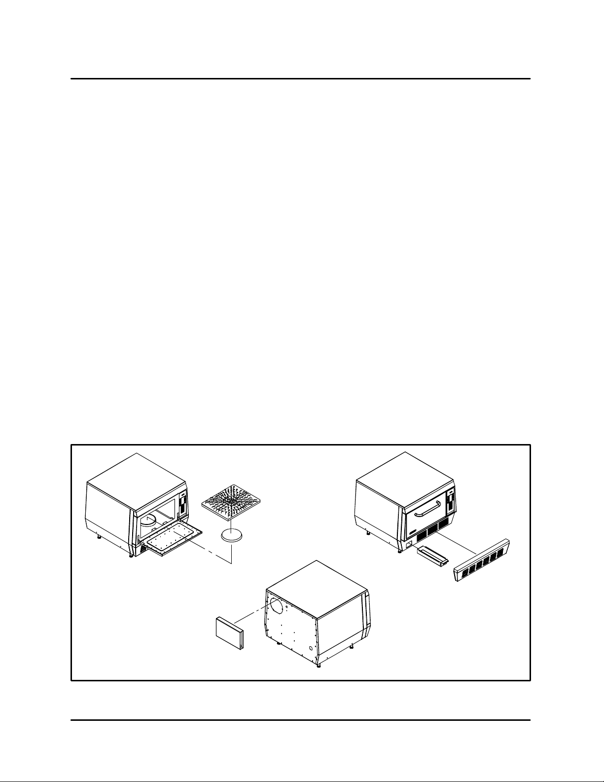
MONTHLY CLEANING
1. Remove and clean the exhaust cover from the
back of the oven.
Cook Platter
Exhaust
Cover
Waveguide
Cap
FIGURE 1
2 --- 1
Grease
Tray
Lower Access
Panel
Page 14
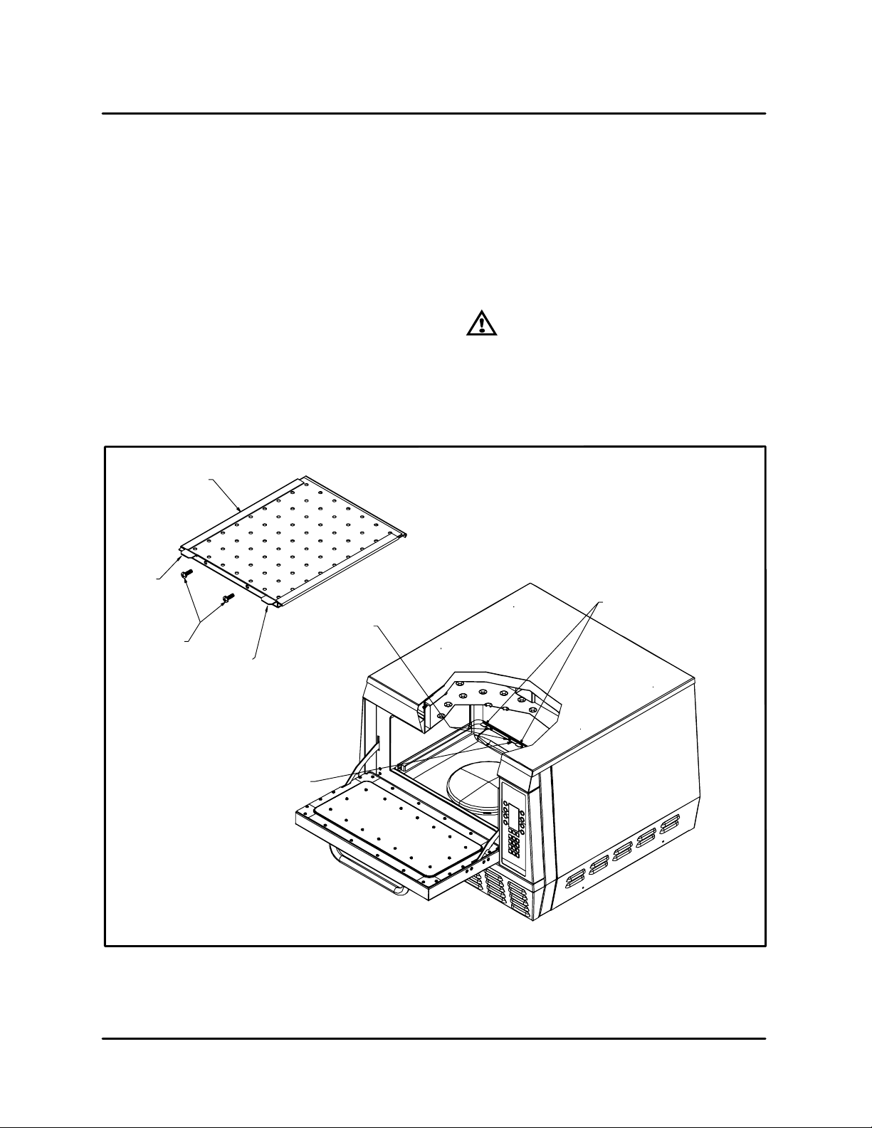
OVEN CAVITY FILTER CLEANING
CLEANING & OPERATING
Filter should be cleaned once a week, depending
on food product and unit run time.
1. Turn the C70 off and disconnect power to the
unit.
2. Allowthe unit to coolbefore cleaningthe filter.
3. Open the oven door.
4. Carefully remove the ceramic platter.
5. The oven cavity filter is located in the bottom
left corner .
6. Remove the two screws.
7. Pull the two tabs on the filter to remove it.
8. Clean the filter with soap and warm water.
Filter
Tab
9. Clean the oven filter cavity.
DO NOT reach into the air return more than
six inches.
10. Reinstall the filter and secure with the two
screws.
DO NOT over tighten the screws.
WARNING!!
DO NOT operate the unit without the
oven filter installed. Failure to do so
may result in prematurefailure of the
heater element.
Tabs
Screws
Screws
Tab
Filter
FIGURE 2
2 --- 2
Page 15

ACCELLIS C70
GLOSSARY OF COMMON OPERATING TERMS & ERROR MESSAGES
OVEN OPERATING COMPONENTS
Display --- Prima ry interfa ce t o relay messa ges to
the operator.
Keypad --- Primary interface for the operator to
control the oven.
Cook Chamber --- Cavity in which the food prod-
ucts are cooked.
PRODUCT RECIPES
Recipe --- The food product recipe programming
consistsoftime, percentage ofhotairflow(AIR)required and microwave (MW) level required.
Cook Cycle --- Time of operation for a recipe.
Cook Event – Segment of a recipe, up to 6 events
can be used for each recipe.
Duration --- Time, in seconds, of a single cook
event.
Air --- Percent of convection air flow during a cook
event.
MW --- Percent of microwave used during a cook
event.
Cook Temperature Set Point --- Tempera ture
should be a constant parameter. The same cook
temperature should be used by all cook recipes.
MODES
Mode – The software environment which allows
certain operations t o occur. There a re several
modes, STANDBY, COOK, WARM UP and COOL
DOWN in which the oven can operate.
Standby Mode --- The standby mode is similar to
oven off. In standby there is no power to the oven.
There is power to the control, however, the oven
will not operate in standby mode.
Warm-Up Mode --- Mode to bring the oven up to
the cook temperature set point.
Cool-Down Mode -- - Turns off all oven components
except the cooling fan and circulation blower.
ERROR MESSAGES
LO MAG CURR – the magnetron transformer is
drawing less than 7 amps. The normal current
draw is approximately9 amps. The current draw is
beingmonitored bythecontrol boardwhich has an
inductance ring on it.
LOCOOK TEMP – thetemperature s et for the C70
is not being maintained. It is referenced by two J
type thermocouples.
MAG OT – the snap disk on the magnetron has
overheated and has tripped.
BLOWERSTAT –the controlboardisnotreceiving
the proper output from the convection (blower)
motor speed control.
LO MAG FLUX – there is a small antenna in the
launchtube ofthe waveguide. Thisantenna orRF
cable is attached to the control circuit board. The
control circuit board amplifies the signal and looks
foracertainfluctuationwhichindicates themagnetronis operating and the stirrer blade inthe launch
tube is rotating. When not cooking a minimum
change of 20 is being looked for. When you are
cooking a product a minimumchange of 10 is being looked for. When viewing the RF display, it will
fluctuatequicklywithamaximumvalueof120(plus
or minus 20).
ELECTOVR TMP – the j type thermocouple connected to the control board is above 140_F.
OVEN DOOR OPEN – (during cook cycle) the
cooking door has been opened during a cook
cycle and has not been closed properly.
Cook Mode --- Mode used to perform the normal
oven operations, such as, monitor the key pad for
requests to cook or change mode, and maintain
the oven at the cook temperature set point.
2 --- 3
Page 16
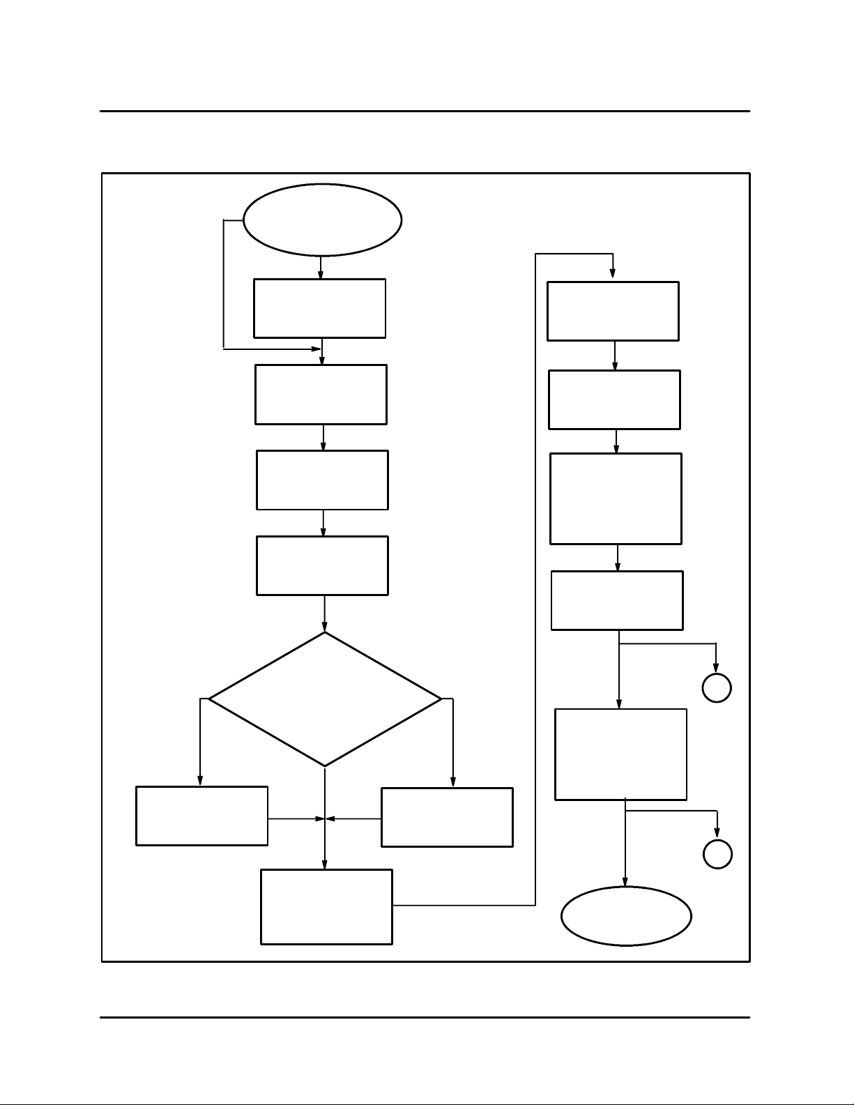
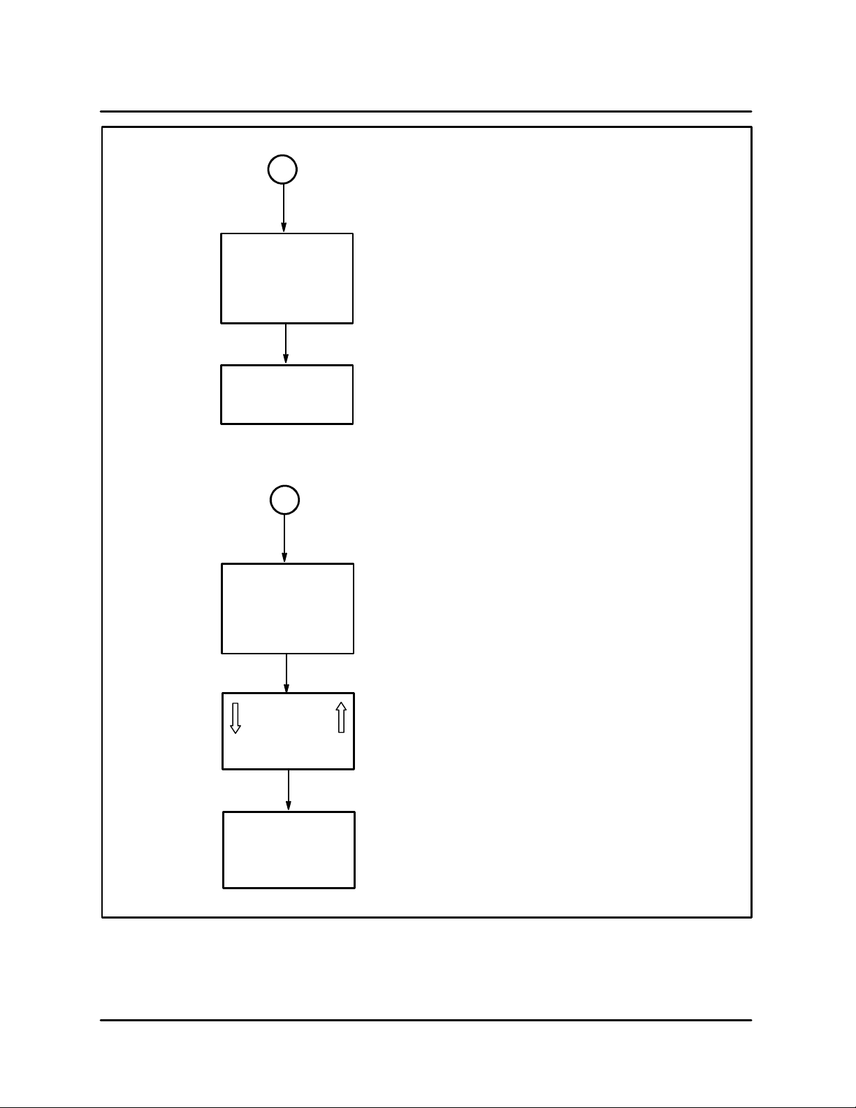
OPERATIONAL FLOW CHART
START
(Blank Display if off
for over one hour)
If the oven has
been used in
the last hour,
proceed to
here.
Press any key
to initialize
CLEANING & OPERATING
Press soft key to
select menu.
Display reads
OVEN OFF
Press soft key
next to OVEN ON
(to right of display)
Display reads
SET TEMP XXX
PRESS ENTER
Use theARROW keys to change
the temperatue. The range is
_
between 350
_
increments).
in 25
Press ENTER to
accept value.
Display reads
COOLING DOWN
F and 520_F
The oven will
default to the
programmed temperature
if no change
If oven
temp
high
is entered.
If oven
temp
low
Display reads
WARMING UP
Press soft key
to pick submenu.
Display reads
XX:XX
COOKING
MENU
SUBMENU
Cooking begins
Open Door
When finished
display reads
DONE
Please remove
food from oven
Cook More
A
See
next
page
Display reads
READY TO COOK
(oven beeps)
(oven to set temp)
2 --- 4
Press
STOP key
B
See
next
page
Page 17
ACCELLIS C70
Press RESUME
If the door is open during
A
the cook cycle
Display reads
PAUSE
GROUP
ITEM
RESUME
to continue
If you do not press the stop key you can
B
cook the product more if it is not done
Display reads
COOK MORE
BROWN MORE
COOK & BROWN
Use the
arrows keys
to set the time
(20 sec increments)
Press key to right
or left of desired
cook option
COOK MORE --- Microw ave only
BROWN MORE --- Convection only
COOK & BROWN - -- Microwave & Convection
FIGURE 3
2 --- 5
Page 18

PROGRAMMING FLOW CHART
Press BA C K key
until the display
reads OVEN OFF
Press the
ARROW keys
at the same
time for 3 seconds
Display reads
ENTER ACCESS
CODE
UNLOCKS DISPLAY
Enter Access code
8317
then press ENTER
Press soft key next
to display you wish
to change.
CLEANING & OPERATING
<GROUP>
Use the number/letter keys to
enter the desired menu name.
NOTE: Curser under
selected letter.
<ITEM>
Use the number/letter keys to
enter the desired submenu
name.
<SET TEMP>
(350_ to 525_)
in 25_ increments
CURSER & MOVEMENT KEY
NOTE: 1. Curser under figure indicates it is selected.
2. Curser advances to next figure after 3 seconds.
3. Use left or right soft key to select figure if you
make a spelling mistake.
4. Use UP or DOWN arrow keys to advance to any
desired line item.
5. Save,testorusebackkeytoexitwhenfinished.
L1
L2
L3
L4
GROUP A
ITEM 1
SET TEMP XXX
%AIR
TIME
1 00:00 0 0
2 00:00 0 0
3 00:00 0 0
4 00:00 0 0
5 00:00 0 0
6 00:00 0 0
TEST
%WAVE
SAVE
R1
R2
R3
R4
TIME
XX:XX
%AIR
XXX
%WAVE
XXX1
A. Set time from 00:01 to
59:59. Setting the time
to00:00 willend therecipe.
B. Set % of blower speed
from 10% to 100% in 10%
increments.
C. Set % of microwave
from 10% to 100% in 10%
increments.
D. You can program up to 6
events per item. When an
event is finished, the next
onebegins. Set a zerotime
to end a programmed
event.
Press SAVE. (TEST runs
program without saving it.)
Press BA C K key to exit
program mode.
2 --- 6
Page 19

CHAPTER 3
TEST
Page 20

ACCELLIS C70
TEST FUNCTION QUICK REFERENCE
DISPLAY PAGE 1
Press the BACK
until the display
OVEN OFF.
BACK & ENTER
keys at the same
time for 3 seconds
Display reads
ENTER ACCESS
UNLOCKS DISPLAY
Select XXX code
press ENTER
key
reads
Press the
CODE
and
CCXX - -- thermocouple cooking cavity temperature
BL O W ER– runstheblower motorin10%increments
ELEC–thermocoupleelectricalcompartmenttem-
perature
STEST – initiates the self test function
HXXX – thermocouple heat exchanger temperature
HEATER -- turns on HOT AIR heater element
MGTRON – (press & hold) runs the magnetron circuit
DIAG – runs the cooking display w/status indica-
tors at the bottom of the display
DISPLAY PAGE 2
CCXX - -- thermocouple cooking cavity temperature
HXXX – thermocouple heat exchanger temperature
S/N – for entering the serial number of the C70
CCC --- number of cook cycles
PIN – enters a new 3 digit password number
F/C -- Fahrenheit or Celsius temperature display
FF – view and reset cook fault counters
FIGURE 1
The test function allows the technician to operate
components individually and get diagnostic
information. There are 2 pages of test functions.
To change pages use the DOWN ARROW key.
Refer to the brief descriptions on this page to help
determinewhichtest functionwillhelp you. Before
operating a test function, read the full description
of the test function on these following pages.
IAF – allows you to view or change the Idle Airflow
3 --- 1
Page 21

TEST FUNCTION DETAILED DESCRIPTION
TEST
TO ENTER TEST FUNCTION MODE
1. F rom the standby mode, press and hold both
ARROW keys simultaneously for three seconds.
2. The display reads:
ENTER ACCESS CODE
3. Use the NUMERIC keypad to enter the following access code:
8317
4. Press the ENTER key.
TEST FUNCTION OPTIONS
The test screen displays the CC (cook cavity)and
HX (heat exchange) temperature at the top of the
screen.
The control displays page one of the test function
options. Press the DOWN ARROW key to display
page two of the test functions options.
To access a test function,press the corresponding
soft key repeatedly.
TEST FUNCTION OPTIONS -- PAGE 1
L1
L2
L3
TEST
CC XX HX XX
BLOWER HEATER
____ELEC
MGTRON
R1
R2
R3
Blower Speed
The BLOWER key (L2) increments the blower
speed in 10% steps. When the blower speed is
100%, the next press sets the speed to 0%.
Electronic Compartment Temperature
The _ELEC key (L3) displays the temperature inside the electronic enclosure.
Self Test Function
The STEST key (L4) initiates a self-test function to
test all major components oftheoven.Press the L4
key once to run the self test. Press the BACK key
to return to the standby mode.
Heater Test
The HEATER key (R2) turns the heater on or off. If
the heaters are on, pressing the R2 key turns the
heaters off. If the heaters are off and the maximum
heater temperature (700_F) is not exceeded,
pressing the R2 key turns the heaters on. If the
blower speed is 0, the blower speed is set to the
Idle Airflow.
Magnetron
The MGTRON key (R3) is a press and hold key to
test the magnetron. If the magnetron filamentsare
off when the MAG k ey is pressed, the message
“MAG WARMING UP” is displayed. After a 3 second delay or if the filamentsare already on, “MAG
ON,RFxxx”isdisplayed.“xxx”isthefluctuatingmicrowave power measured in the wave-guide(ifRF
detector is installed). Any time the MAG key is released,themagnetronturns off. The filamentpower (magnetron cooling fan and mode stirrer) remains on for three minutes.
Diagnostic Display
L4
NOTE: The R1-4andL1-4 are used for key identification in
STEST
Test Function Options --- page 1
this manual. They do not appear on the oven.
DIAG
R4
FIGURE 2
The DIAG key (R4) turns on or off the diagnostic
displayfeature. This featureadds temperature displays to the menu group screens.
While cooking, cook setting parameters are displayed when diagnostics are enabled.
With diagnostics enabled, status indicators are
displayedonthe lower left of the display.Each indicator is a letter, which is displayed in a positive
sense when the status conditionis on. The letter is
reversed when the conditionis off. There a re eight
status indicators:
3 --- 2
Page 22

ACCELLIS C70
P --- Cook door primary interlock switch
S --- Cook door secondary interlock switch
M --- Cook door monitor interlock switch
t --- Magnetron over temperature switch
h --- Heater turn on command
H --- Heater current det ected
A --- Blower motor speed control “run” status
W --- Magnetron current detected
TEST FUNCTION OPTIONS -- PAGE 2
L1
L2
L3
TEST
CC XX HX XX
S/N F/C
CCC
FF
R1
R2
R3
3. Usethe NUMERIC KEYPAD tochange thedigitsasfollows:
A.) Press the key once to enter the first letter.
B.) Pressthe keytwice toenter thesecond letter
C.) Pressthe key three timestoenter thethird
letter.
D.) Pressthe key fourtimesto enter the fourth
letter if applicable or number.
E.) Pressthe key fivetime toenter the number
if applicable.
4. Press the ENTER KEY to store the new name.
Cook Cycle Count
The CCC key (L3) displays the cook cycle count.
The count is incremented when the cook process
completes at least the first event. The count includes test cooks selected w hile in the edit function. Toreset the count, press 0 key.
PIN Number
The PIN key (L4) is used to enter a new personal
identification number (password) for accessing
the test and edit functions. When the button is
pressed the display reads:
L4
NOTE: The R1-4andL1-4 are used for key identification in
PIN
Test Function Options --- page 2
this manual. They do not appear on the oven.
IAF
R4
FIGURE 3
Serial Number
NOTE: Thisshouldonlybeneededwheninstalling
a new control. The S/N is located on the
back of the oven.
The first press of the S/ N key (L2) displays the
oven’s twelve-digit serial number. Use the following procedure to enter the serial number.
1. Press the S/N key again to enter the edit mode.
2. Press the ENTER KEY. A right and left arrow key
appear on the bottom of the display. These arrowsare usedtonavigatewithinthe text.Use the
L4 SOFT KEY to move the curser to the left.Use
theR4 SOFTKEYto movethe curser to theright.
ENTERPIN___
Usethe numerickeypadtoenter thenewPIN.Only
numbers are applicable for the PIN.
Temperature Units
The F/C key (R2) alternately selects fahrenheit or
celsius for temperature displays.
Cook Fault Counter
The FFkey (R3) is used to read andreset theoven
cookfaultcounters. Repeat pressingthe FFbutton
to view five fault counters. Press the 0 key to reset
the fault counter displayed. The faults include:
D
BLOWER STA T (blower motor speed controller)
D
LOW COOK TMP (temperature)
D
LOW MAG CURR (current)
D
MAG OVR TMP (over temperature switch)
D
ELEC OVR TMP (electronics)
Idle Airflow
The first press of the IAF key (R4) displays the selected idle airflow. Subsequent presses of the IAF
button increment the idle airflow in 10% steps.
Whentheidleairflowis50%,thenextpresssetsthe
airflow to 10%.
3 --- 3
Page 23

CHAPTER 4
ELECTRICAL
COMPARTMENT
Page 24

ACCELLIS C70
KEYSEQUENCEOFOPERATION---FAILUREMODEANALYSIS
Unit will perform self test of component functions.
1. No display. Check items:
#2 (fuse)
#4 (24VDC power supply).
#9(SMT controllerboard). Check for 5VDCon
P5 pin 1+ & 3 --- .
NOTE: Check cable connections.
2. Door interlock switch error. Check items:
#5 (primary & monitor door switch) (secon-
dary switch on left side of oven not shown.)
#6 (K2 relay)
#1 (circuit breaker)
Seepage4---5.
3. Mag current low. Check items:
#1 (circuit breaker) (CB1)
#3 (convection high heat OT)
#6 (K3 relay filament heat)
5. Mag Thermo SW. Check items:
#17 (magnetron)
#11 (magnetron cooling fan.)
NOTE: Attached to back of the magnetron is
the Mag thermo snap disk.
6. Blower motor defective message. Check
items:
#18 Blower motor speed controller.
#19 Convection (blower) motor
NOTE: Reference pages 5---5 and 5---6 for
BMSC defective messages.
7. Heat Exchanger Thermo OPEN. Display
shows the # 999. Check items:
#9 (SMT controller board connector (J2) pins
#37 & #38).
NOTE: Check pin connections.
NOTE: Reference pages 4---2 through 4---4.
8. CC Heat thermo OPEN. Display shows the
# 999. Check items:
#8 (K4 SS relay for magnetron)
#13 through #17.
NOTE: Reference page 6---4 and 6---6 for
component testing.
4. Mag Fluc Low.Checkitems:
#12 (stir motor)
# 9 (SMT controller board RF cable connec-
tion.)
#13 through #17
NOTE: If (RF) value on display is (0 or 1). No
RF power is present. If (RF) value is
displaying a number value like (60)
with little fluctuation then check item
#12 (Stirrer fan in launcher tube may
needtobeinspected.This involvesremoving the quartz seal.)
NOTE: Reference page 6---4 and 6---6 for
component testing.
#9 (SMT controller board connector (J2) pins
#37 & #38).
NOTE: Check pin connections.
NOTE: Reference pages 4---2 through 4---4.
9. Heat Rise Low. Check items:
#7 (K7 SS relay for heater)
#18 (convection motor controller)
NOTE: Reference pages 4---2 through 4---4.
forheatertestinginformation.
4 --- 1
Page 25

ELECTRICAL COMPARTMENT
ELECTRICAL COMPONENT LOCATIONS
9
5
6
1
2
8
7
18
10
19
3
4
13
14
15
1 Circuit Breaker BC1-35A
2Fuse
3 Convection Heat High Limit
4 24VDC Power Supply
5 Door Switch Assembly under
circuit breaker
6 K1 High Limit Relay
6a K2 Relay for Monitor Circuit
6b K3 Relay for Filament Heat
6c K6 Relay for Magnetron Cooling Fan
7 K5SolidStateRelayforHeaterElement
8 K4 Solid State Relay for Magnetron
Transformer T1
FIGURE 1
4 --- 2
121117
9 SMT Controller Board
10 ElectricalCompartmentCoolingFan#1
11 Magnetron Cooling Fan
12 Stir Motor
13 Diode
14 Capacitor
15 Filament Transformer
16 Magnetron Transformer T1
17 Magnetron
18 Blower Motor Speed Controller
19 Convection Motor
16
Page 26

ACCELLIS C70
ELECTRICAL COMPONENT DESCRIPTION WITH VOL TAGE INFORMATION
Item 6 K3 Relay for Filam ent Heat
CAUTION!
Magnetron voltage potential of 4800
VAC
NOTE: To test if 208/240 VAC is present use CB1
Terminal L2A white wire as neutral.
NOTE: Totest if voltage at coil is present, measure
voltage across coil. Voltage should be
present when activated.
COMPONENTS
Item 1 Circuit Breaker CB1-35A
D
208/240 VAC Trip Coil Terminals (1 & 2).
D
208 VAC Line Input.
D
208/240 VAC Line Output.
Item 2 Fuse
D
Qty (2) 10 AMP Fuse
NOTE: Remove front access panel to expose fuse
holders.
Item 3 Convection Heat High Limit
D
208/240 VAC (N/O) Terminals (13 &14).
_
NOTE: Manual reset trip temp 350
C or 670_F
Item 4 24 VDC power supply
D
Line power in (L & N) 208 VAC.
D
Output (+V & ---V) 24 VDC.
Item 5 Door Switch Assy
D
24 VDC Switch #1 C.D.P.
D
24 VDC Switch #2 C.D.S.
D
24 VDC Switch #3 C.D.M.
Item 6 K1 High Limit Relay
D
208/240 VAC Coil terminals (8 & 1).
D
208/240 VAC Input Terminal (6).
D
208/240 VAC Output Terminals (5).
Item 6 K2 Relay for Monitor circuit
D
24 VDC Coil Terminals (8)+24 VDC & (1)---24
VDC.
D
208/240 VAC Input Terminal (6).
D
208/240 VAC Output Terminal (7).
D
24 VDC Coil Terminal (8)+24 VDC & (1)---24
VDC.
D
208/240 VAC Input Terminals (6 & 3).
D
208/240 VAC Output Terminals (5 & 4).
Item 6 K6 Relay for Magnetron
Cooling Fan
D
24 VDC CoilTerminals24 VDC InputTerminals
(6)---24VDC & (3)+24VDC.
D
24 VDC Output Terminals (5)---24VDC &
(4)+24VDC.
Item 7 K5 Solid State Relay for Heater
Element
D
24 VDC Coil Terminals (3+ & 4---).
D
208/240 VAC Input Terminal #1.
D
208/240 VAC Output Terminal #2.
Item 8 K4 Solid State Relay for Magnetron
Transformer T1
D
24 V DC Coil Terminals (3+ & 4 --- )
D
208/240 VAC Input Terminal #1.
D
208/240 VAC Output Terminal #2.
Item 9 SMT Controller Board
D
24 VDC Line Input P2 location #16
D
24 VDC Line return location P2 #22
D
Current Sense Transformer CT1.
NOTE: Amp draw on wire going to Mag is 9
AMP.
D
Current Sense Transformer CT3.
NOTE: AmpdrawonwiregoingtoHeateris 19
AMP.
Item 10 Electrical Compartment Cooling
Fan #1
D
24VDCOutputfrom(---V24VDCPowersupply
&OT#1terminalNO).
NOTE: OT #1 closes at 120f.
Item 11 Magnetron Cooling Fan
D
24 VDC Input from K6 Terminals (5 & 3).
D
24 VDC Output from K6 Terminals. (5 & 4).
4 --- 3
Page 27
ELECTRICAL COMPARTMENT
Item 12 Stir Motor
D
208/240 VAC Connector J1 (1 & 2)
NOTE: Energized by K3 Filament Heat contactor.
Item 13 Diode
D
Referencepage6---4fortestprocedure.
Item 14 Capacitor
D
Referencepage6---4fortestprocedure.
Item 15 Filament Transformer
D
Referencepage6---4fortestprocedure.
Item 16 Magnetron Transformer T1
D
Referencepage6---4fortestprocedure.
Item 17 Magnetron
D
Referencepage6---3fortestprocedure.
Item 18 Blower Motor Speed Controller
D
208/240 VAC Line power location (N & 230V)
D
Motor output (U,V,W) 240 VAC 3 phase.
24 VDC Motor control inputs and outputs.
D
#4) FWD RUN 24 VDC input.
D
#7) 0 to 10 VDC Speed input example, 1
VDC = 10% RPM, 2 VDC= 20% RPM.
D
#9) Speed Command.
D
#11) 24 VDC Common
D
#12) Running B.M.R
Item 19 24 VDC Motor control inputs and
outputs.
D
208/240 VAC Input from B.M.S.C Terminals
(U.V.W)
Relay K1, 2, 3 & 6 Terminal Locations
Relay Base
24VDC
208/240VAC
21
6
22
7
24
11
3
12
2
14
Relay Coil
24VDC
208/240VAC
FIGURE 2
5
1 ( --- )
4
8(+)
4 --- 4
Page 28

ACCELLIS C70
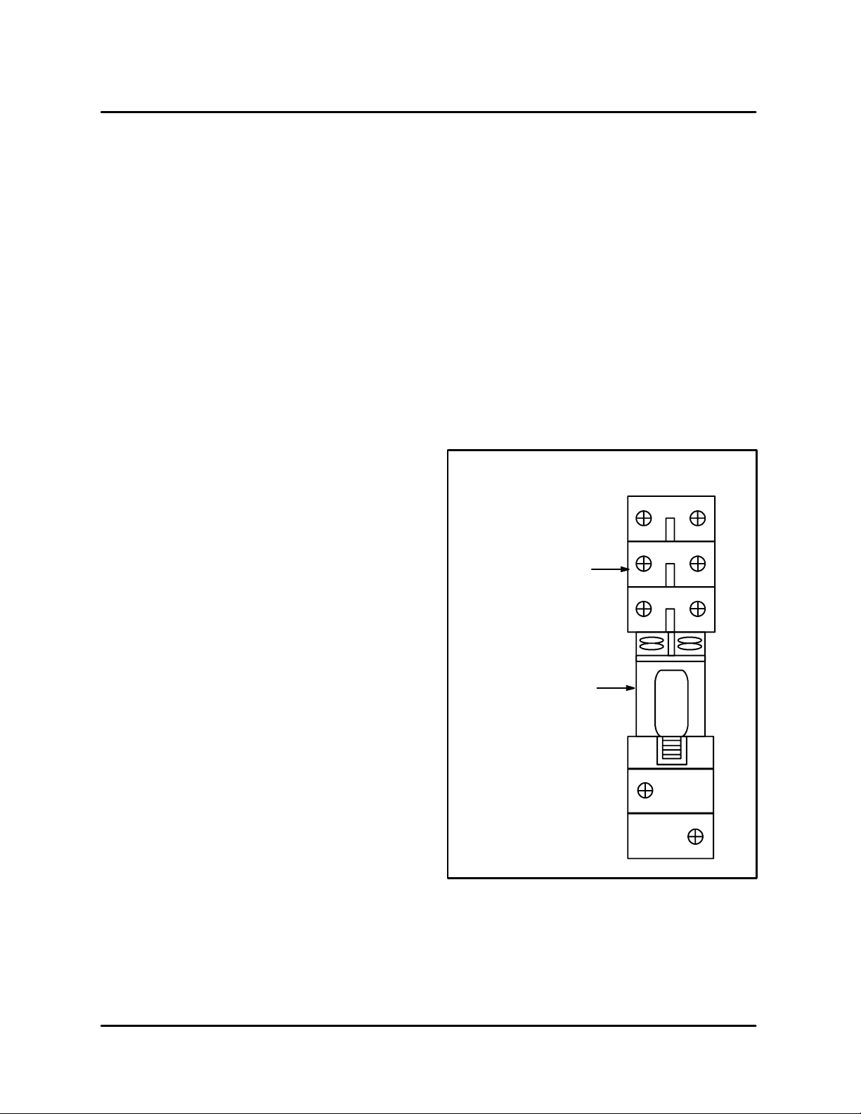
DOOR SWITCHES AND CIRCUIT BREAKERS
DOOR SWITCHES
The C-70 has 3 door switches. One door switch is
locatedon the left hand side andis calledthe secondary switch. Two switches are located on the
right hand side. One is called the primary switch
and the other is called the monitor switch. The
monitor switch must close before the primary
and secondary switches close or the circuit
breaker willtrip. Thecircuitbreaker will also trip
if a door switch is defective and not closing. To
determinewhat sequence thedoors areclosingin,
youwill needto access the Test mode andactivate
theDiagnosticmode(Seepages3---1to3---3).By
doing so, you will activate the status indicators at
thelowerleftbottom ofthedisplay.Slowly closethe
CIRCUIT BREAKER TRIP CHART
Component Possible Cause/Circuit Information
Magnetron transformer The magnetron transformerwilldraw approximately9 amps when func-
tioning properly. Check winding resistances (See Page 6---5) A 3 amp
draw indicates the diode is bad.
Solid state contactor for Magnetron (K4)
(See above for correct current draw.) The coil operates on24v dc. Solid
state relays tend to fail closed. Check with VOM meter.
dooronceyou have activatedthe Diagnosticmode
and observe the status indicators. You may need
to adjust the strike screw on the door cam so the
switches close in t he correct sequence. The
mounting screws for adjusting the door closer can
also be adjusted if needed. (The mounting brackets for the door are slotted to allow a djustment. )
CIRCUIT B REAKER
The circuit breaker is a manual reset switch. It will
trip if the total current draw is more than 35 amps
orifitisactivatedbyasafetyfault. Referto thechart
below to help you determine what problem you
may have if the circuit breaker has tripped.
Hot air heater element Use VOM meter.
240V element is 12ohms / current is 20amps
208V element is 9 ohms / current is 23 amps
Solid state contactor (K5) for
hot a ir element
High limit & K1 relay High limit tripped (670F). Reset withs crewdriver. Check thermocouples
Door switch closure (Read first paragraph on this page.) CheckSwitches with VOM meter.
(See above for correct current draw.) The coil operates on24v dc. Solid
state relays tend to Fail closed. Check with VOM meter.
(See page 4 --- 8 and 5 --- 3) Verify contact points (6 to 5) on K1 relay ares
open. Check K5.
TABLE 1
4 --- 5
Page 29

DOOR SWITCH ADJUSTMENT
ELECTRICAL COMPARTMENT
TOOLS R EQUIRED:
D
7/16 Allen wrench
D
5/16 socket and ratchet or 5/16 box & open
end wrench
D
#2 Phillips head screwdriver
D
Blodgett Door Switch Adjustment Kit, part
#T0631
D
RF survey meter
DOOR SWITCH ADJUSTMENT INFORMATION
The goal of this adjustment procedure is toadjust
the door switches so they close and open in the
propersequence. There arethree doorsw itches in
the C70 oven. They are called the Monitor switch,
thePrimaryswitch,and the Secondaryswitch. The
secondary switch is located on the left-hand side
ofthe oven. The Primaryand Monitor switch arelocated on the right hand side of the C70 oven. The
Monitorswitch is mounted closesttothe ovencavity, with the Primary switch mounted next to it.
When closing the oven door, the Monitor switch
mustclosefirst, thenthe Secondaryswitchand the
last switch to close is the Primary. The door
switches willopenin theopposite sequence when
the door is opened; first the Primary, then the secondary, and the last switch to open is the Monitor
switch.
Thisprocedureis written to insureproper oven operation and compliance with Federal regulations.
ADJUSTMENT
NOTE: Readtheseinstructionscompletelybefore
starting this procedure.
1. The C70 oven must be at room temperature to
adjust the door switches.
2. Withthe power offto theC70, removetheoven
body top and both sides. Use the security
screwdriver provided in the Blodgett Shim kit
where needed.
3. Loosenor removethe five screws securingthe
top oven molding across the top of the oven.
See FIGURE 3 for location of the screws.
4. Reapply power to the C-70 oven.
5. Enter the TEST function mode. Refer to page
3---2 for instructions. Activate the Diagnostic
mode and read the short paragraph on this
test function. You will be using the status indicators enabled in this mode to insure proper
switch adjustment. You will be monitoring the
P, S, and M status indicators when adjusting
the door switches. Remember, when the indicator letter is dark, the switch is open. When
the indicator letter is bright, the switch is
closed. With the door open, manually operate
the Secondary switch lever and observe the
changein thestatus indicatoronthe displayto
demonstrate the sw itch open and closedindication.
6. Shut off the circuit beaker (down position)
CB-1.
7. Locate the Blodgett shim kit, part number
T0632. This kit contains a total of 12 shims. All
the shims are engraved with their dimensions.
Threeshimsareofthesamethickness.Locate
matching shims and separate them into 4
groups on top of the oven. Group the shims
from left to right in the following order: 0.060,
0.048, 0.030, and 0.024. This is the order you
willbe using them in. The other tools in this kit
will be used later.
8. Inspect all shims for flatness prior to starting.
Any bent edges or non-planar (not flat) surfaces will cause incorrect measurements. Repair or replace damaged shims before proceeding.
9. Before starting to do any adjustments, review
FIGURE 4.IntheupperlefthandsideofFigure
1isa detailof the doorswitch and itsactuating
screw. Compare this figure to the door
switches on the C70 oven with the oven door
is closed. The activator switch screw (5) must
be engaging the door switch interlock switch
lever (7). If these two parts are not engaging,
it may be necessary tomove the whole switch
assembly by adjusting the two Phillipsscrews
holding the door switch assembly in place.
10. Be sure the actuator switch screw at any time
during this door switch adjustment isnot overdriving the interlock switch lever (7) so that itis
hitting the switch body (6).
11. All door switch adjustments for the rest of this
procedurewill bedonebylooseningthe nut on
an actuating switchscrew (5/16 nut) and then
using the Allen head wrench (7/64)to turn the
actuatorswitch screw. It is recommendedthat
4 --- 6
Page 30

ACCELLIS C70
adjustments be made in 1/4or less turn increments.Whena doorswitchadjustment iscompleted, tighten the nut on the actuator switch
screw while holding the actuator sw itch screw
head in place with the (7/64) Allen head
wrench.
12. Openthe C70ovendoor.Slidethe0.060shims
in place as shown in FIGURE 3. The longer lip
with the etching must be on the inside of the
door. (Allshims must be placed as such when
installed on the oven door.)
13. Hold the loosened (if not removed) top oven
molding up so when you open and close the
door with the shims in place such that the
shims will clear the molding.Shimming it with
cardboard (not provided) works well. See
FIGURE 3.
14. Slowly close the oven door. All door switches
must be open. (The Monitor status indicator
letter (M) will be dark. The Primary(P)andSecondary (S) status indicators will be dark.)
15. Open the door 2 inches, then release it. The
door should close firmly and all switches must
be open. (With the door closed, the Monitor
status indicator letter (M)w ill be dark. The Primary (P) and Secondary (S) status indicators
will also be dark.) Repeat and readjust the
doorswitch activatorscrew asneededtomeet
these criteria forboth thedoor closings before
continuing. (Step 14 & Step 15)
16. Remove the 0.060 shims and re-shim the door
with the 0.048 shims.
17. Slowly close the oven door. The Monitor door
switch must be closed. (With the door closed,
the Monitor status indicator letter (M) will be
bright.)At this time, donotworryabout the other indicatorstatus letters. Youw ill be adjusting
them later in this procedure.
18. Openthedoor2inches,then releaseit. Thedoor
should close firmly and the Monitor switch must
be closed. (With the door closed, the Monitor
status indicator letter (M) will be bright.) At this
time, do not worry about the other indicator status letters. Yo uwill be adjusting them later in this
procedure. Repeat and readjust the door switch
activator screws as needed to meet this criteria
for both the door closings before conti nuing.
(Step 17 & Step 18).
19. Remove the 0.048 shims and re-shim the door
with the 0.030 shims. Slowly close the door.
20. Adjust the Primary and Secondary switch ac tuator screws so they are just open when the
door is closed. (With the door closed the Primarystatus indicatorletter(P)will be dark and
theSecondary statusindicatorletter(S)willbe
dark. The Monitor indicator letter (M) will be
bright.) Repeat and readjust the door switch
activator screws as needed to meet these criteria before continuing.
21. Open the door 2 inches, then release it. The
door should close firmly.The Primary and Secondary switches must be open when the door
is closed. (With the door closed the Primary
status indicator letter (P) will be dark and the
Secondary status indicator letter (S) will be
dark. The Monitor indicator letter (M) will be
bright) Repeat and readjust the door switch
activator screws as needed to meet these criteria for both the doorclosings before continuing. (Step 19 & Step 20)
22. Adjust the Secondary switch actuator screw
1/4 turn clockwise.
23. Remove the 0.030 shims and re-shim the door
with the 0.024 shims. Slowly close the door.
24. The Primary, Secondary,and Monitorswitches
must be closed. (With the door closed the Primary status indicator letter (P) will be bright
and the Secondary status indicator letter (S)
will be bright. The Monitor indicator letter (M)
will also be bright.) Repeat and readjust the
door switch activator screws as needed to
meet these criteria before continuing.
25. Open the door 2 inches, then release it. The
Primary, Secondary, and Monitor switches
must be closed. (With the door closed the Primary status indicator letter (P) will be bright
and the Secondary status indicator letter (S)
will be bright. The Monitor indicator letter (M)
will also be bright.) Repeat and readjust the
door switch activator screws as needed to
meet thiscriteria before continuing.(Step 23 &
Step 24)
26. While opening and closing the door gently,
look at the status indicator letters. (When you
close the door, the Monitor, Secondary, and
Primary will close in that order .When you open
the door, the Primary, Secondary, and Monitor
will open in that order.) Repeat and readjust
the door switch activator screws as needed to
meet these criteria before continuing.
27. The next procedure will confirm the opening
and closing of the door switches in the correct
sequence using the Blodgett door leak test
tool, part # T0629.
4 --- 7
Page 31

ELECTRICAL COMPARTMENT
28. If you removed the top oven molding, reinstall
itat this time. Ifyou didnotremovethe topoven
molding, tighten the mounting screws.
29. Install the Blodgett leak test tool as shown on
page NO TAG. Snug up the bottom 2 bolts to
the face of the oven door. Adjust the top bolt
so it is not hitting the top oven molding.
30. Slowly tighten and loosen the top bolt on the
Blodgett leak test tool and observe the status
indicatorletters. Theymust open and closeas
Display in diagnostic mode:
M=CDM, P=CDP, S=CDS
(When indicator is bright contactsare closed.When indicator is
dark, contacts are op en.)
Oven Molding Screws
Oven Molding
Screw (inside)
Door Shims
describedin Step 26. Repeat and readjust the
door switch activator screws as needed to
meet these criteria.
31. The C-70 oven must now be checked for microwave leakage. Refer to page NO TAG.
32. If you can not obtain the proper switch closing
sequence, it may be necessary to adjust the
door cam (roller) positions as described inthe
door replacement and installation procedure.
Oven Molding
Screw (inside)
Insert Card board
Here
Oven Molding
Door Shim
Cook
Door
Removable Lower
Access Panel
Cook Door
Secondary
Cook Door Primary
Cook Door Monitor
FIGURE 3
4 --- 8
Page 32

ACCELLIS C70
DOOR REMOVAL AND REPLACEMENT
Tools Required:
D
12” long #2 Phillips screw driver
D
3/8” hex driver
D
3/8” socket with 1/4” ratchet wrench
D
Set of feeler gages
DOOR REMOVAL
1. Remove the side and top panels, top and bottom
plugs, control panel, and perimeter trim piece.
2. Remove the interlock actuator bracket (#3)
and front guideblockassembly(#9) from both
sides of the oven.
NOTE: The guide block assembly may or may
not contain guide block support shims
(#22). Guide block assemblies should
be re-installed in the location they were
removedfrom (i.e. right guide block assembly re-installedon rightside) toprevent potential trailing arm binding.
3. Close the oven door and disconnect the
springs (#8) from both trailing arms (#2).
4. Loosen but do not remove the nuts (#10) that
hold the cam follower assembly (#12) in position, thenrotate both assembliesdown tovertical orientation.
5. Remove the door:
F.) Remove the four 10-32 UNF Philli ps screws
(#15) from the door hinge bar mounti ng
brackets (#13) on both sides of the oven.
G.) Pull the door away from the oven, bottom
first, to slide the hinge bars (#14) out of
their slots. Use caution in removing the
doorto avoidbending the hingebars. Ifthe
bars bind in their slots, gently wiggle the
door to free them.
A.) Slide the trailing arms through the upper
slots and over the rollers.
B.) Slide the hinge bars (#14) through the
lower slots. Use caution in installing the
doorto avoidbending the hingebars. Ifthe
bars bind in their slots, gently wiggle the
door to free them.
C.) Attach the bars to the door hinge bar
mounting brackets (#13) with four 10-32
UNF screw s (#15) on each side (finger
tight). Apply thread-locker to screw
threads prior to installation.
D.) Close the doo r and apply even pressure
(approximately15to20pounds)totheface
of the door to squarely seat the door shunt
on the ov en face. Continue to apply this
force whil e tightening the four screws on
each side (two people are recommended).
3. Install the spring (#8) on each side between
the trailing arm and spring bracket. Any interference between any other component or wiring and the springs or trailing arms must be
corrected before proceeding.
4. Install the front trailing arm guide blocks (#9):
A.) Assemble (per side) one spacer block
(#17), two guide blocks (#18), two
spacers (#19), and two screws (#20) with
lock-washers (#21).
NOTE: The guide block assembly may or may
not contain guide block support shims
(#22). Guide block assemblies should
be re-installed in the location they were
removedfrom (i.e. right guide block assembly re-installedon rightside) toprevent potential trailing arm binding
B.) Install one guide block assembly over
each trailing arm and tighten screws.
H.) Removethe door ,guiding the hooked por-
tion of the trailing arm over the cam follower rollers (#11).
DOOR INSTALLATION
1. Rotatecam follower assembly (#12)down tovertical position to permit the trailing arms (#2) to pass
over the cam follower roller (#11) in step 2.
2. Assemble the door to the oven:
5. Install the interlock actuator brackets (#3):
A.) Open the door.
B.) Attach the interlockactuator brackets to the
trailing arms with two 6-32 UNC screws
(#4), nuts, and lock - washers on each side.
NOTE: As you face the oven front, the right-
handsidebracketis mounted tothe in-
side of the arm; the left-hand side
4 --- 9
Page 33

ELECTRICAL COMPARTMENT
bracket is mounted to the outside of
the arm.
WARNING!!
At the first closing of the door verify that
the brackets do not hit and bend on the
trailing arm guides (#1 and #9). If actuator switch screws (#5) are installed on the
actuator brackets, insure that the interlock switch levers (#7) do not bottom out
on the switch body (#6). If they do, open
the door and back the problem screw(s)
out, again checking for interference with
the guide as the door is closed.
DOOR ADJUSTMENT
1. Adjust cam follower assembly (#12) to tension
the trailing arms (#2) to apply closingpressure:
A.) Close the door.
B.) Rotate the cam follower assembly so that
thetop ofthe trailingarm engages the rear
guide (#1) 0.125 inch (+0.125 ---0.031)
abovethetopofthechamferedleadin.
C.) The cam follower assembly roller (#11)
should be located on the ramp portion of
the trailing arm with 0.020” to 0.050” gap
between the top of the roller and the bottom of the trailing arm radius.
D.) Tightenthe camfollowerbracket nuts(#10).
2. Adjust the interlock switch brackets (#16) and
actuator brackets (#3):
A.) Move the switch brackets as required to
bring the switches (#6) into contact with
the actuator screw(s) (#5).
B.) The switch actuator screw(s) should con-
tact theswitchlevers (#7) at 90°±5°.Bend
the actuator brackets to adjust this alignment as required.
C.) Again, check that the brackets or screws
do not contact the trailing arm guides (#1
and #9) as the door is closed.
D.) Withthedoorclosed,check thatth e actua-
tor screws are centered side-to-side (not
overhanging the edge) on the switch levers. Apply light side-to-side finger pressuretothet railingarm toverifythattherear
guide blocks keep the actuator screws in
position on the sw itch levers.
NOTE: Refer to page 4-- -6 for the final door
switch adju stme n t. This adjustment is
completed after all door adjustment
steps have been completed.
3. Adjust the door pivot position for best alignment
by inspecting for the following conditions:
A.) Ideally, the microwavesealing planes(the
portions of the oven face and door shunt
that overlap each other) should touch,
since as the gap between the sealing
planes increases, it becomes more likely
that the microwave leakage will increase.
However, because of manufacturing tolerances, the microwave sealing planes of
thedoor shunt andthe oven flangeare not
perfectly flat. The best door alignment
minimizes the gaps between the sealing
planes both top and bottom.
B.) If the hinge bars (#14) have been pushed too
far into their brackets (#13) the lower edge of
the sealing planes will be tight and there will
be an excessive gap between the sealing
planes along the top edge. In this po sition,
with the top plug removed, most of the hex
head of the shunt screws will be seen.
C.) Ifthe hinge bars have notbeenpushedfar
enoughinto their brackets the upperedge
of the sealing planes w ill be tight and an
excessivegap willoccurbetweenthe sealing planes along the bottom edge. This
could permit excessive microwave leakage along the bottom edge.
NOTE: To correct B or C: Loosen the door
hingebar screws (#15)on bothsides.
Close the door and apply even pres sure (approximately 15 to 20 pounds)
to both sides of the door to squarely
seat the door shunt on the oven face.
Continue toapplythisforcewhiletightening the four screws on each side
(two people are recommended).
D.) By design there is a 0.030” clearance be-
tween the Phillips head screws securing
the plastic shunt cover and the oven
flange. Verify that one or more of these
screws does not contact the oven flange
and increase the gap between thesealing
planes.Thisconditionmaybeindicatedby
the head ofthe screw (s) marking theoven
flange. If this is thecase, the door may be
4 --- 10
Page 34

ACCELLIS C70
warped or the shunt may not be flat. Adjust, repair, or replace the door so that
when the door shunt is seated squarely
none of the Phillips head screws contact
he oven flange.
E.) Repeat adjustment steps 1 and 2 as re-
quired after completing door alignment.
4. Adjust the interlock switches per procedure
beginning on page 4---6.
5. After adjusting the interlock switches the oven
must be checked for microwave leakage. Refer to the service manual for instructions and
acceptable limits.
ITEM
1 Trailing Arm Guide
2 Trailing Arms
3 InterlockActuator Bracket
46-32UNCScrews
5 Actuator Switch Screws
6SwitchBody
7 Interlock Switch Levers
8Springs
9 Guide Block Assembly
10 Nuts
11 Cam Follower Rollers
12 Cam Follower Assembly
DESCRIPTION
ITEM
13 Door Hinge Bar
14 Hinge Bars
15 10-32 UNF screws
16 Interlock Switch Bracket
17 Spacer Block
18 Guide Blocks
19 Spacers
20 Screws
21 Lock-Washers
22 Guide Block Support Shims
DESCRIPTION
Mounting Brackets
FIGURE 4
4 --- 11
Page 35

C70 SCHEMATIC
ELECTRICAL COMPARTMENT
6B
1
8
2
16
6A
5
12
14
15
6C
17
6
13
3
11
9
10
4
7
18
19
FIGURE 5
4 --- 12
Page 36

CHAPTER 5
CONVECTION CIRCUIT
Page 37

ACCELLIS C70
CATALYTIC CONVERTER
The catalytic converter is installed in the return air
duct behind the heater assembly. The installation
of the catalytic converter requires a catalytic converter inner frame to properly position it in the air
path. The above parts may be ordered in kit form.
Due to the nature of most foods and the physics
governing the operation of the Accellis oven,
grease buildup downstream of the cookingchamber is inevitable. Strict cleaning regiments can
solve a majority of the problems, however, recirculation of undiluted grease saturated air is the
main cause of downstream grease accumulation
and any associated residual flavors.
Theairbornegreasetendstocollectandbakeonto
the oven surface downstream of the cooking
chamber. This grease, due to the high operating
temperatures of the oven, will start to rapidly decompose into derivative organic compounds.
These decompositionalderivatives generally have
positiveand negativeeffectsoncooking;theshorter chainderivativesaddfavorableflavorcharacteristics to the food, while the higher order carbon
chainslend unpleasantflavorcharacteristics,such
as bitter tarry tastes.
Theinstallationofthecatalyticconvertergreatlyeffects the grease handling and any residual flavors
which might build up over time. A properly operating catalytic converter causes t he conversion of
airborne grease into water, carbon dioxide and
small amounts of nitrogen and oxygen. The catalytic converter acts as a combustion chamber for
theairbornegrease.Thecatalystspresentonthe
filterlowerstheignitiontemperature ofthe airborne
grease from approximately 700_F (371_C) to
450-550_F (232-288_C), allowing combustion to
occur. The operating temperature of the oven directly determines the percentage of airborne
grease conversion. A single pass ofthe air stream
yields a 20-30% improvement in air quality.
A problem with the catalytic converter is indicated
by a decrease in the effectiveness of browning
(caused by areduction in airflow) or byflavortransfer from one food group to another.
If you suspect the catalytic converter needs cleaning refer to figures on page 5---2 and below. These
diagrams provide you with a location reference
and exploded view. It is important to carefully removetheinsulationandreplaceitneatly. Themetal
foil helps shield microwave emissions.
Catalytic Converter
Return Air Duct
Assembly Panel
Inner Bracket
Heater
Baffle
Terminal Heat Sheild
The catalyticconverter can be cleaned with a nonlyebasedovencleanerand rinsed.Letthecatalytic
converter air dry before installing.
FIGURE 1
NOTE: 350
settingfor proper operation of
catalyticconverter
_
F minimumoven temperature
5 --- 1
Page 38

CONVECTION CIRCUIT
CONVECTION ELEMENT AND THERMOCOUPLES
The convectionelement is located in the rearback
on the left side of the oven. It is controlled by one
ofthe twosolidstate relays(K5), locatedin the top,
center of the controlcompartment ofthe oven. The
K5 relaycoil operates on 24VDC w hich issupplied
fromthe I/Ocontrolcircuitassembly.Thetemperature is referenced by two “K” type thermocouples.
D
The HX thermocouple is in the rear of the oven
by the catalytic converter.
D
The CC thermocouple islocated on the topleft
side of the oven near the front by the door.
To test the operation of the convection circuit, run
theoveninthetestmode.Seepage3---2forSelf
Test information. The element will not energize if
the convection motor is not running. You will have
to troubleshoot the convection motor and its controller before continuing.
The resistance of the hot air element for 240VAC
units is 12 ohms, it draws approximately 20 amps.
The resistance of the hot air element for 208VAC
units is 9 ohms, it draws approximately 23 amps.
One of the wires to the hot air element is l oo ped
through an inductance coil transfo rmer on the I/O
control circuit assembly. It must draw a mini mum
current of7.5 amps to satisfy thecircuit. If it does not,
thedisplayreads HTRCURRLOW.Ifathermocouple
is open the display reads 999. The thermocouples
are held in place with a compression fitting.
Before replacing a thermocouple, inspect the 40
pin connector where the thermocouples plug into
the I/O control circuit assembly. It is possible you
just have a loose connection. Try unplugging and
reconnecting the 40 pin connector. When replacinga defectivethermocouple, itisimportant toreinstallthenew thermocouplesoitprotrudes aspecific distance inside the oven cavity. See FIGURE 2.
Replace the thermocouple as follows:
1. Makeanotewheretheoldthermocoupleexited the compression fitting.
2. Measure the distancefrom the exit point tothe
end of the thermocouple.
3. Mark this distance on your new thermocouple
withamarkerorapieceoftape.
4. Install the new thermocouple.
Air Duct Panel
(with element)
CC
Thermocouple
Remove and reinstall insulation carefully to eliminate microwave emmissions
FIGURE 2
5 --- 2
HX
Thermocouple
Rear View
High Limit
Thermostat
Page 39
ACCELLIS C70
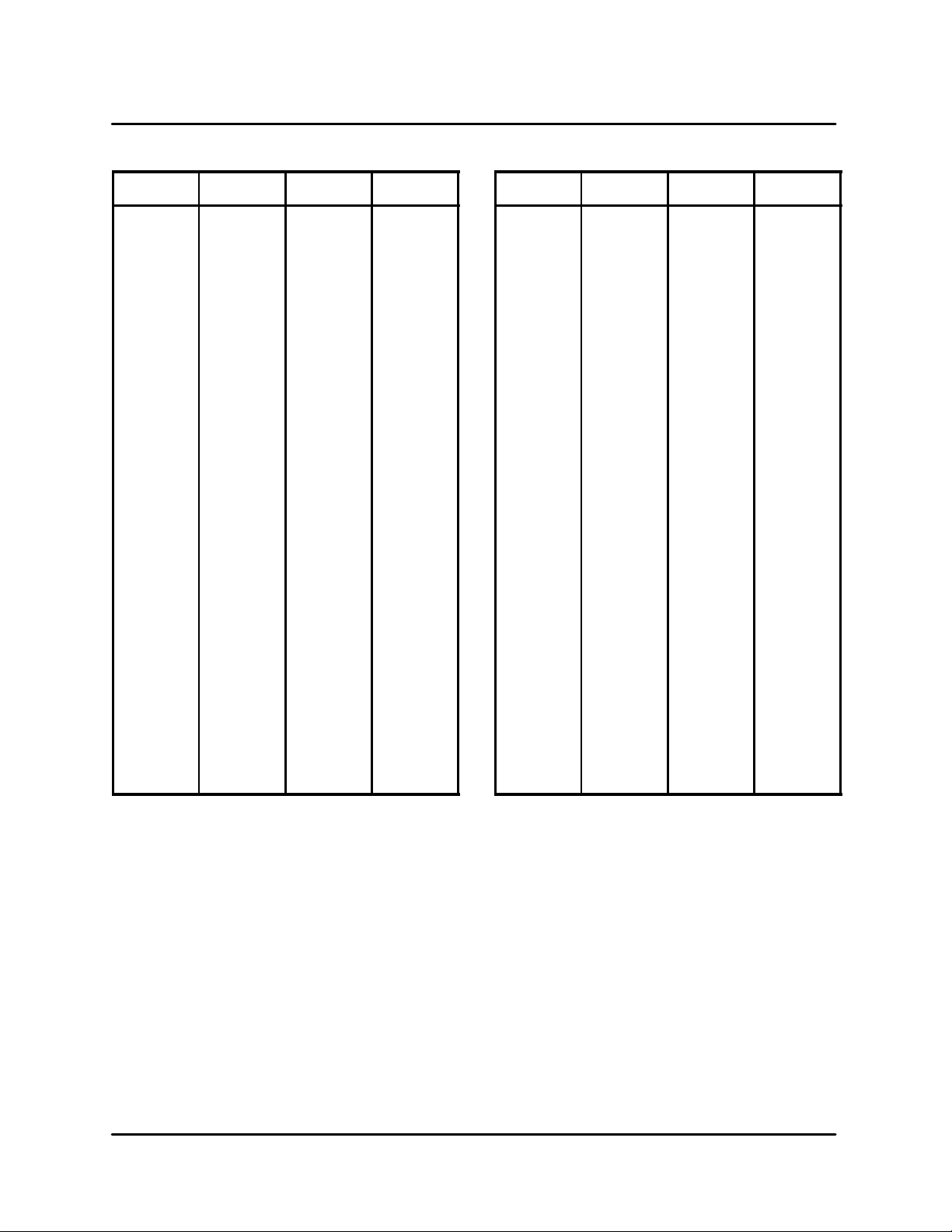
THERMOELECTRIC VOLTAGE IN MILLIVOLTS --- TYPE K THERMOCOUPLE
_F _C Reading +5_F
70 21 0.843 0.955
80 27 1.068 1.181
90 32 1.294 1.407
100 38 1.52 1.634
110 43 1.748 1.862
120 49 1.977 2.091
130 54 2.206 2.321
140 60 2.436 2.551
150 66 2.666 2.781
160 71 2.896 3.012
170 77 3.127 3.243
180 82 3.358 3.473
190 88 3.589 3.704
200 93 3.819 3.934
210 99 4.049 4.164
220 104 4.279 4.394
230 110 4.508 4.622
240 116 4.737 4.851
250 121 4.964 5.078
260 127 5.192 5.305
270 132 5.418 5.531
280 138 5.634 5.756
290 143 5.868 5.98
300 149 6.092 6.204
_F _C Reading +5_F
310 154 6.316 6.428
320 160 6.539 6.65
330 166 6.761 6.873
340 171 6.984 7.094
350 177 7.205 7.316
360 182 7.427 7.538
370 188 7.649 7.76
380 193 7.87 7.981
390 199 8.092 8.203
400 204 8.314 8.425
410 210 8.537 8.648
420 216 8.759 8.871
430 221 8.983 9.094
440 227 9.206 9.318
450 232 9.43 9.543
460 238 9.655 9.768
470 243 9.88 9.993
480 249 10.106 10.219
490 254 10.333 10.446
500 260 10.56 10.673
510 266 10.787 10.901
520 271 11.015 11.129
530 277 11.243 11.358
540 282 11.472 11.587
TABLE 1
5 --- 3
Page 40

CONVECTION CIRCUIT
CONVECTION (BLOWER) MOTOR OPERATION
OVERVIEW
The convection (blower) motor is a variable speed
convection motor which operates from zero rpms
up to 7000 rpms. The blower motor speed is controlled bya SP200 AC drive control. This controller
converts the 200V to 240V single phase input to a
variable 3 phase output(230/460VAC). Thespeed
is controlled by low voltage inputs (0 to 10 VDC)
which are applied to pin #7 on the SP200 AC drive
control from the control circuit card. If the convection (blower) motor is replaced, carefully remove
and reinstall the insulation to eliminate microwave
emissions. You must remove the entire motor assembly with the blower wheel to perform any work
on either item.
TROUBLESHOOTING
Torun theconvection(blower)motorindependent ly ,youwillneedtooperate the AccellisintheCOOL
DOWN mode.
To operate in COOL DOWN mode:
1. Turn the Accellis on.
2. Allow the unit to complete the start-up self
diagnostic test.
3. Press the COOL DOWN button.
If the convection (blower) motor is not running:
1. Verify the plug connector on the top two pins
on terminal P3, on the control circuit board is
in place. See page 6---6.
2. Inspectthe SP200AC drive motor control.See
FIGURE 3. The SP200 AC drive motor has a
single LED.
If the LED is green, the controller is operating
properly and has the correct inputs.
If the LED is flashing red, countthe number of
timestheLEDflashesbeforeitrepeatsitsflashing sequence. Refer to the fault code chart on
page 5--- 6.
The operating parameters of the SP200 AC drive
controla re preprogrammed into the control. Refer
to FIGURE 3 to verify voltages and wiring.
Terminal Block Connections
2 = +10VDC
3 = Function Loss/Reset
4=ForwardRun
7 = 0 to 10VDC
8 = Common
11 = Relay Common
12 = NO Relay Contact
Windings
Resistance
for MAC motor
2.6 ohms
MOTOR
GND
RED
BLU
WHT
GND
RED
BRN
BLK
FIGURE 3
GND
1
2
3
4
5
6
7
8
9
10
11
12
Power In
200 to 240 VAC
WHT BLK
Output
230/460 VAC
5 --- 4
Page 41

ACCELLIS C70
BLOWERMOTOR CONTROLLERFAULTCODES& TROUBLESHOOTING
NOTE: Ifnofaultconditionexists,theLEDwillbegreen.Ifafaultconditionexists,theLEDwill flashredwhen
a local keypad is not connected.All faults can be reset by cycling the reset control input, pressing
the stop key, or cycling power , except as noted in the Corrective Action column below.
#of
LED
Flashes
Fault
Description
Fault Cause Corrective Action
2 Control Input
2 Function Loss
D
Illegal control input sequence
D
StartattemptwhileSTOP
(function loss) input is off
3 Under Voltage
4 Over Voltage
5 Drive Overload
5 Motor Overload
D
Low input line
D
Temporary loss of input line
D
High input line
D
Decel time too fast
D
Overhauling load
D
Excessive driven load
D
Excessive driven load
6 Over TemperatureDOperating environment is too hot
D
Fan is blocked or not operating
D
3-wire:VerifyStartand Joginputs
are not both ON
D
2-wire: V eify that only one input
(Forward, Reverse, or Jog) is ON
D
Verify STOP (function loss) input
is ON before attempting to start
drive.
D
Check input line to verify voltage
is within operating specifications
D
Check input line to verify voltage
is within operating specifications
D
Increase decel time
D
Reduce the load
D
Verify P---02 is set correctly
D
Reduce the load
D
Verifythe ambient temperatureis
<50_
D
Verifyclearanceabove/below drive
7 Over Current
(300%)
8 Bad Keypad
Connection
9 Negative Slope
D
Excessive driven load
D
Shaft rotation blocked
D
Excessive driven load
D
Output wiring is incorrect or shorted
D
Bad connection from keypad to
drive
D
Conflicting parameter values
5 --- 5
D
Check for fan obstruction. Replace if necessary
D
Reduce the carrier frequency (P - 64)
D
Reduce the load
D
Check for obstructions to shaft
rotationor reduce excessive load
D
Increase accel/decel time
D
Verify output wiring is correct
D
Verify keypad is properly connected to drive
D
Adjust values of parameters P-50
through P-54
Page 42

#of
g
grounde
d
Short
LED
Flashes
CONVECTION CIRCUIT
Corrective ActionFault CauseFault
Description
10
10
10
10
10
10
Ground Short
Phase to Phase
Short
D
Phase U
D
Phase V
D
Phase W
D
Phase U--- V
D
Phase U--- W
D
Phase V--- W
11 Checksum FailureDParameter value out of range
12 Microprocessor
D
Internal processor error
Fault
TABLE 2
D
Verify output wiring is correct
D
Verify output phase is not
rounded
D
Verify motor is not damaged
D
Verify ouput wiring is correct
D
Verify motor is not damaged
D
Load default parameter values
(P-60=1), then cycle power. If
fault persists, replace drive.
D
Cycle power. If fault persists, replace drive.
5 --- 6
Page 43

ACCELLIS C70
This page intentionally left blank.
5 --- 7
Page 44

CHAPTER 6
MICROWAVE CIRCUIT
Page 45

ACCELLIS C70
MEASURING FOR MICROWAVE RADIATION LEAKAGE
The following RF emisssions test must be performed every time a service call is done on an
Accellis oven. Report your findings on the work
order.
NOTE: Your micro survey meter should be cali-
brated annually.
The following areas must be measured when performing the RF test.
D
Cook Door
D
Filter Door (if applicable)
D
Atany placeon theoutside ofthe oven(withall
covers in place).
Check for microwave leakage as follows:
1. Placealoadintheovenfortesting.Theload
must meet the following specifications:
A.) Load must b e 275 ml +/--- 15 ml of water.
B.) The w ater should be 77_F(25_C) +/- _5.
C.) Thecontainer must be a low form, 600 ml
beaker with an insidediameter of approximately3.35” (8.5cm) and madeofan electrically non-conductive material such as
glass or plastic.
2. Enter the diagnostic mode. Refer to page 3- --2
for instructions for accessing diagnostic mode.
the external surface of the oven, measured
priorto acquisitionby purchaser, and thereafter, 5 milliwatt per square centimeter at
any point.”
A.) The tip of the probe should be touching the
oven surface being measured with the
probe handle perpendicular to the surface.
B.) Move the probe counterclockwisearound
the perimeter of the doorstarting fromthe
upper right corner at a speed of less than
0.5” per second. Be sure to probe entire
doorperimeter, returningtothe upperright
corner.
7. Exit the diagnostic mode.
8. Repeat STEPS 1 and 6 with the cook door
closed.
WARNING!!
If the unit fails the radiation test, the oven
must be taken out of servi c e immediately
until the defect is corrected. In addition, the
Code of Federal Regulations 21 SubpartC,
1002.20 requires that leakage readings of
over 5 mW/cm
2
MUST be reported to t h e
manufacturer . If further information is required for this test please call Accellis Service at 1-888-992-6624.
3. Position the Blodgett door leak test tool on the
door handle. See FIGURE 1 for correct positioning of the the leak test tool.
4. Tightenthe topscrew to slowlyopen the door.
Stop when the control panelindicates that any
door switch has disengaged.
5. Loosen the top screw slowly until the control
panel indicates that the open door switch has
re-engaged.
6. Test for microwave leakage as follows:
Thistest must bedone inconformance with 21
CFR, Ch1, Part 1030---Performance Standard
for Microwave and Radio Frequency Emitting
Product. Part 1030.10 Microwave Ovens. (C)
Requirements --- (1) Power Density Limit. “The
equivalent plane wave power density existing in the proximity of the external oven surface shall not exceed 1 milliwatt per square
centimeter at any point 5 cm or more from
Door Leak TestTool
FIGURE 1
6 --- 1
Page 46

MAGNETRON CIRCUIT
MICROWAVE CIRCUIT
Overview of a microwave circuit
Allmicrowavecircuitshaveamagnetronandavoltage doubler circuit. A voltage doubler for a magnetroncircuit consistsofa special step-uptransformer, a capacitor, and a diode. In the C70 a separate
(B)
(A)
+
0
MAG SCHEMATIC
2400
VDC
2800
+ ---
Electron
Flow
+
---
0
--- ---
POWER IN
--- o r ---
transformer is used t o preheat the filiment for the
magnetron for better operation.
NOTE: If the voltage exceeds 500VDC, an X-ray
emission test must be performed. Refer to
UL923, paragraph 51.1.2, page 93.
+
(A)
---
2800
+
0
(B)
--- --- ( C )
MAG SCHEMATIC
2400
VDC
+ ---
Electron
Flow
0
4800
VDC
AT (B)
AT (C)
1. Powerintothetransformer(Seediagramabove(AtoB))
2. Transformer steps up voltage to approximately 2400VAC.
3. Electron flow is from ground, through the diode, then through the capacitor, then through the
transformer.
4. The capacitor charges to approximately 2800VDC.
5. Voltage in is on the downward swing, from point B to C (See diagram above)
6. At point C, the capacitor is stillcharged and the transformer is at –2400VAC. They add together
to make a –4800 volt potential. At this potentialthe magnetron launches.(Think ofth e magnetron as a large tube. It finally has enough potential between the anode and cathode to permit
electron flow.) The electron flow is converted into RF energy at 2450 MHz with about 60% efficiency.
FIGURE 2
6 --- 2
Page 47

ACCELLIS C70
MAGNETRON TESTING
Checking a Magnetron for Open or Shorted Fil-
WARNING!!
The microwave circuit cannot be worked
on with the unit on. The unit must be disconnected from thepower source. Failure
to do so could result in injury or death.
WARNING!!
TheHV Capacitormust be dischargedbe-
fore proceeding by using a pair of insulatedplierstounhookthewireonthepositive side of the diode and shorting the
terminal to ground.
MAGNETRON REMOVAL AND REPLACEMENT
aments:
1. Disconnect the AC power source and discharge the High Voltage Capacitors.
2. Isolate the magnetron from the circuit by removingthe wires from the F and FA terminals.
3. Anohmmeter connectedbetween thefilament
terminals (F, FA) should indicate a reading of
less than 1 Ohm.
4. A continuitycheck between either filament terminal and the magnetron chassis shouldindicate an infinite resistance (open).
1. Remove door hinge bar support angle.
2. Remove magnetron cooling fan.
3. Unplug and remove magnetron.
See View A
4. Install new magnetron.
5. Check the oven for microwave leakage. Refer
to page 6-- -1 for instructions.
View A
Door
Hinge Bar
SupportAngle
Magnetron
Magnetron Cooling Fan
FIGURE 3
6 --- 3
Page 48
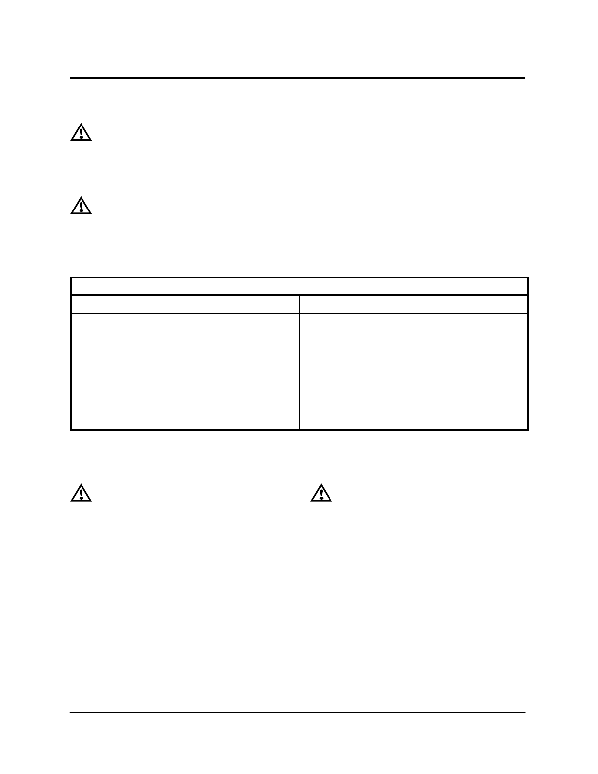
COMPONENT TESTING
WARNING!!
The microwave circuitcannot be serviced
with the unit on. The unit must be disconnected from the power source. Failure to
do so could result in injury or death.
MICROWAVE CIRCUIT
TRANSFORMER TESTING
1. Disconnect the power source and discharge
the capacitor.
2. Isolate the transformer from the circuit. (Wires
are labeled but remember where they go)
WARNING!!
TheHV Capacitormust be dischargedbe-
fore proceeding by using a pair of insulatedplierstounhookthewireonthepositive side of the diode and shorting the
terminal to ground.
TRANSFORMER SPECIFICATIONS
Main Transformer (Anode) Filament Transformer
Primary DCR 0.58 Ohm. Primary DCR (1---2) 23.2 Ohm
Secondary DCR: (5---6) 46.39 Ohm
(5---7) 54.00 Ohm
Input Voltage : 208---240 VAC, 50/60 HZ In put Voltage : 208/240 + 10%, 50/60 HZ
Input Current: 9.0 Amps RMS Input Current: 0.42 Amps @ 208 VAC
Anode Voltage: 2400 VDC Peak @ 0.415 Amps Filament Voltage: 4.6VAC@14Amps
TABLE 1
DIODE TESTING
3. Check impedance of the primary and secondary windings. See TABLE 1.
4. Filament winding should read less than 0.1
ohms.
5. Reconnect wires.
(1---3) 27.8 Ohm
Secondary DCR: (4---5) .020 Ohm
0.35 Amps @ 240 VAC
CAPACITOR TESTING
WARNING!!
DO NOT attempt to measure HV directly.
1. Isolate diode from circuit.
2. Connect the meter leads to the diode terminals.
3. Resistance readings (open) should be indicated in the reverse direction.
4. Resistance readings in the forward direction
may be indeterminate.
5. Ifthere is continuity inbothdirections (shorted
diode).
WARNING!!
Discharge the capacitor after disconnect-
ingthe power and prior to servicing. Nev er assume the internal discharge resistor
has completely discharged the capacitor.
1. Disconnect the oven from the power source.
2. Isolate the capacitor from the circuit.
3. Fully discharge the capacitor.
4. Connectthe ohmmeter between thecapacitor
terminals. The meter should indicate a low impedance and then slowly return to infinite resistance.
5. Reverse t he ohmmeter leads. Repeat step 4.
6. Check each terminal to case. Infinite resistance (open) should be indicated.
6 --- 4
Page 49

ACCELLIS C70
TRANSFORMER SPECIFICATIONS
Anode Transformers Filament Transformers
Primary DCR 0.58 Ohm (1---2) 23.2 Ohm
(1---3) 27.8 Ohm
Secondary DCR (5---6) 46.39 Ohm
(4---5) .020 Ohm
(5---7) 54.00 Ohm
Input Voltage 208---240 VAC, 50/60 Hz
208/240 ¦ 10% 50/60 Hz
Input Current 9.0 Amps RMS 0.42 Amps @ 208 VAC
0.35 Amps @ 240 VAC
Anode Voltage 4500 VDC Peak @ 0.415 Amps 4.6VAC@14Amps
WARNING!!
Use extreme caution when taking any cur-
rent readings. Failure to do so can result
in death or serious injury.
(1 --- 3)
240VAC
COMMON
27.8 OHM
(1 --- 2)
200/208VAC
PRIMARY
23.2 OHM
FILAMENT TRANSFORMER
BACK VIEW
3
2
FRONT VIEW
240V
200/208V
208---240
VAC INPUT
(4---5) 0.20 OHM
4.6VAC SECONDARY
45
1
T2 FILAMENT TRANSFORMER
3
2
1
T3 OR T4
T1 ANODE TRANSFORMER
2
1
T1 OR T2
PRIMARY
COMMON
4
5
3
4
7
60Hz
6
CAPACITOR
5
NOT USED
1.05uF (60Hz)
1.2uF (50hZ)
50Hz
HV
15KV
HV DIODE
FA
WARNING!!
When replacing the anode transformer,
remove the varnish around the mounting
holes to insure proper grounding.
ANODE TRANSFORMER
REAR VIEW
7
50Hz
60Hz
6
5
HV ANODE WINDING (SECONDARY)
(5---6) 46.39 OHM
(5---7) 54.00 OHM
F
MAG1
4500 VPK
415 MA
FILAMENT
4
WINDING
3
(SECONDARY)
(1 --- 2)
2
208---240VAC
(PRIMARY)
1
0.58 OHM
FIGURE 4
6 --- 5
Page 50

CONTROL CIRCUIT BOARD
MICROWAVE CIRCUIT
To Initialize a New Board
1. Press Back & Enter simultaneously until
prompted “ENTER PIN --- --- --- --- ”.
2. Type ERAS. Then press ENTER.
3. Type the letter E. Then press ENTER.
NOTE: For U.S.A models complete step (4)
4. EnterthePIN#XXX.Tocompleteprocedure.
NOTE: Latest code will default the ovento thereg-
istrationstateand theserialnumber willbe
zeroed. This will enable a service agent to
get into the oven using 000 as a reg code.
Be sure to enter the serial number into the
oven after registration is disabled per the
above instructions.
Magnetron Level Potentiometer Adjustment
NOTE: This procedure must be done after re-
placement of the controller board.
1. Placethe oven in the test functionmode asfollows:
A.) From the standby mode, press and hold
both ARROW keys simultaneously for
three seconds.
B.) The display reads:
ENTER ACCESS CODE
C.) Usethe NUMERIC keypadtoenter thefol-
lowing access code:
8317
D.) Press the ENTER key.
2. Place amicrowave dishwith approximately9.3
oz. (275 ml) of cool water in the oven.
3. Press and ho ld the MG TRON key . Observe the
reading on the keypad display.Adjust theamplifier
gain on R24 on I/O controller board. Refer to
FIGURE 5. T urnthe screw clockwiseto reduce the
output until the maximum reading is 120 ± 20.
NOTE: Thedisplayed reading varies greatly due
to the stirrer blade motion. Observe the
reading for at least 10 seconds.
4. Press and ho ld the MG TRON key . Observe the
oven keypad display . Verify the number displayed
varies corresponding to stir blade motion.
5. The differencebetween the highand lowpeak
values must be greater than 20.
(On rear) inductance coil
magnetron 9 amps
(On rear) inductance coil
for HX 20-23 amps
FIGURE 5
6 --- 6
P3
R24
NOTE: Top
two pins
covered
Amplifier Adjustment Screw
Page 51

ACCELLIS C70
NOTES:
6 --- 7
 Loading...