

Page 1
GB
Service & Installation Manual
For BCM Electric Oven
“Manual Control”
Page 2

Table of Contents
Data Plate 3
Installation and connection
-Water connection 4
-Drain connection 5
-Electrical connection/survey of supply lines 6
Start Menu 7
Oven set-up 8
Set –up Mode U 9-10
Test Mode 11
Test Mode D0-D6 12
Test Mode D7-D15 13
Test Mode D16-D20 14
Test Mode D21-D28 15
User Menu 17
User Menu B1-B7 18
User Menu B8-B13 19
User Menu B14-B21 20
User Menu B22-B24 21
Error Codes 22
-Error Code List 23
-Error Codes Guide
Notes 24
Sequence of operation
-Off / On Mode Operation 1
-Hot Air / CombiOptima Operation 2
-Steam / Reheating Operation 3
-Cooling down / Preheat operation 4
Manual Controller
Water level Sensor
BCM Start up Guide
Diagnostic Mode D-Level
Wire Diagram
-Wire Schematic_Diagram 1-8
-Understanding Wire Schematic 2-8
- 2 -
Page 3
Installation and Connections
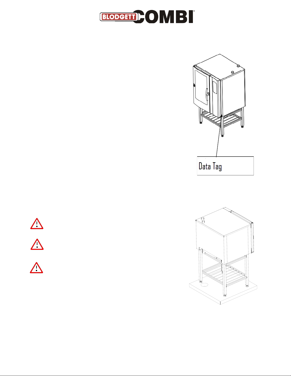
Data Plate
When communicating with BLODGETT, we kindly ask
you inform us of the serial number of the oven that is
stated on the approval plate. The approval plate is
located on the right-hand corner post of the oven
cabinet, as shown below.
The BLODGETT Technical Support, whose experience
and expert knowledge are at your disposal, can be
contacted at tel. # 800-331-5842 and fax # 802-652-2814.
Drain connection
From the factory, the BLODGETT ovens are equipped with
a drain system that removes surplus water from the oven
chamber. This water may be condensed water from the
products, or it may occur when the oven chamber is cooled
down with cold water, or when the oven chamber is cleaned.
Connection
authorised plumber, to an open or to a
closed drain.
It is recommended that a water outlet
is available/established in the floor of
the room where the oven is located.
must
be carried out by an
The drain must never end directly beneath
the oven.
The drain must be of
-resistant material, have a diameter of at least 2” (50mm)
and a fall of at least 3° or 5%.
copper
or an equally temperature
Page 4

Water Connections
BLODGETT ovens have one or two water connections. Two is most common.
To facilitate cleaning and service, the oven should be connected with an approved flexible ¾” hose
and the permanent installations should be fitted with a stop-tap and a non-return valve.
Before connecting the oven to water, flush the tubes thoroughly. Connect the oven.
Hardness of the water: 80-100 PPM
pH level 7.0-8.0
Total Dissolvable Solids: 100 PPM
Chloride: max. 0 PPM
Sulfate: max. 40 PPM/Gal
Conductivity: min. 75 microsiemens
Water pressure: min. 36 PSI (2.5 bar) dynamic pressure (when CombiClean activated.
When CombiWash not activated: min. 22 PSI (1.5 bar), max. 87 PSI (6
bar).
Water temperature: max. 70°F (20°C)
If the water temperature exceeds 70°F (20°C), problems with regard to ClimaOptima
calibration and cooling of the oven may occur.
The water connection must be carried out by an authorised plumber in accordance
with existing rules and regulations
To ensure that the water quality is in conformity with the above requirements, the
installation of a water filter in front of the water connection to the oven is
recommended.
1) 1 connection for raw water for the condensation jet (cold water). Located at the back.
2) The installation of a particle filter (0.25mm) is also recommended.
3) 1 connection for the steam generator and the jet in the oven chamber. Must meet the
requirements applying to water supplied to household appliances; however, hot water with a
temperature not exceeding 125°F (50°C) can be used. Located at the front.
Electrical Connections
When you connect the oven, you should:
Comply with federal, state and local rules and regulations.
The electrical connection
existing rules and regulations.
An approved plug outlet or a safety cut-out
oven can be disconnected during installation and repair. The safety cut-out must be able to cut
off all poles with a total distance of break of at least 3 mm. Each of the two units in a stacked
arrangement (Combi-Plus) must have its own plug outlet or safety cut-out.
The warranty does not cover incorrect connection.
must
be carried out by an authorised electrician in accordance with
must be located close to the oven so that the
- 4 -
Page 5
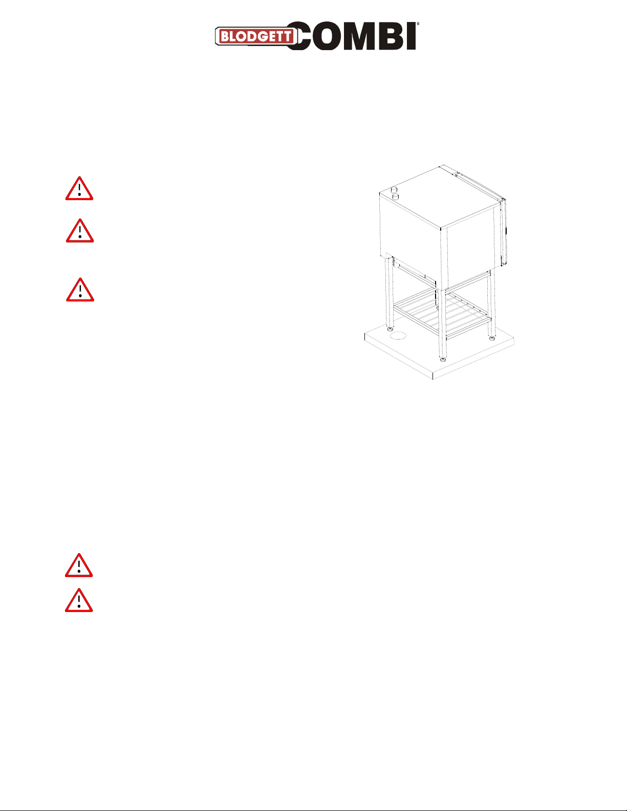
Installation and Connection
Drain connection
From the factory, the BLODGETT ovens are equipped with a drain system that removes surplus water
from the oven chamber. This water may be condensed water from the products, or it may occur
when the oven chamber is cooled down with cold water, or when the oven chamber is cleaned.
Connection
plumber, to an open or to a closed drain.
It is recommended that a water outlet
is available/established in the floor of
the room where the oven is located.
The drain must never end directly beneath
the oven.
The drain must be of
an equally temperature-resistant material, have a
diameter of at least 2” (50 mm) and a fall of at
least 3° or 5%.
must
be carried out by a license
stainless steel, cooper
or
Installation and Connection
Electrical connection/survey of supply lines
The electrical connection
rules and regulations.
The wiring diagram is located in the motor compartment.
The terminal for the electrical connection is located behind the right side plate.
An approved plug outlet or a safety cut-out
oven can be disconnected during installation and repair. The safety cut-out must be able to cut
off all poles with a total distance of break of at least 3 mm. Each of the two units in a stacked
arrangement (CombiPlus) must have its own plug outlet or safety cut-out.
The warranty does not cover incorrect connection.
When you connect the oven, you should:
must
be carried out by an authorised electrician in accordance with existing
must be located close to the oven so that the
• Follow the installation instructions and the information given on the rating plate.
• Comply with federal, state and local rules and regulations.
Page 6

Checking before Use
The oven should be checked before you start using it.
On the outside
•
Check that the oven has not been damaged in transit (dents, scratches, etc.)
•
Check/adjust the height and check that the oven is placed level (horizontally)
•
Check/adjust oven door
• Connections
•
Check for correct water connection
•
Turn on water supply
•
Check for leaks
•
Turn off water supply
•
Check and clean dirt filter
•
Turn on water supply again
•
Check hand shower
•
Check for correct electrical connection
•
Check connection to drip tray
•
Check for correct mounting of drip tray
•
Check for correct fall of hose from drip tray, and check for leaks
•
Check for correct exhaust and drain connection
•
Clean oven
•
Apply steel oil
• Oven chamber
•
Check that filter housing is mounted correctly
•
Check interior light
•
Clean oven
• Operation panel
•
Check and adjust, if necessary, each of the preset values
•
Heat up the oven at 485°F (250°C) for approx. 5 min.
The installation checklist and the instruction checklist (appendices 1 and 2) should be
filled in and returned to BLODGETT 30 days after the installation, at the latest.
Blodgett Fax # 802-652-2814
- 6 -
Page 7
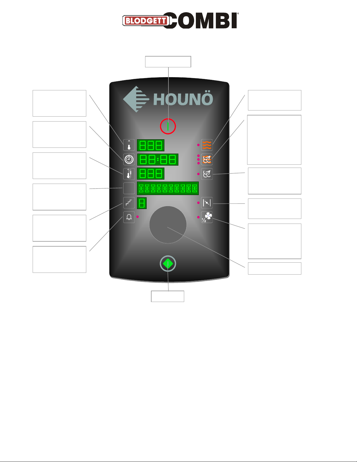
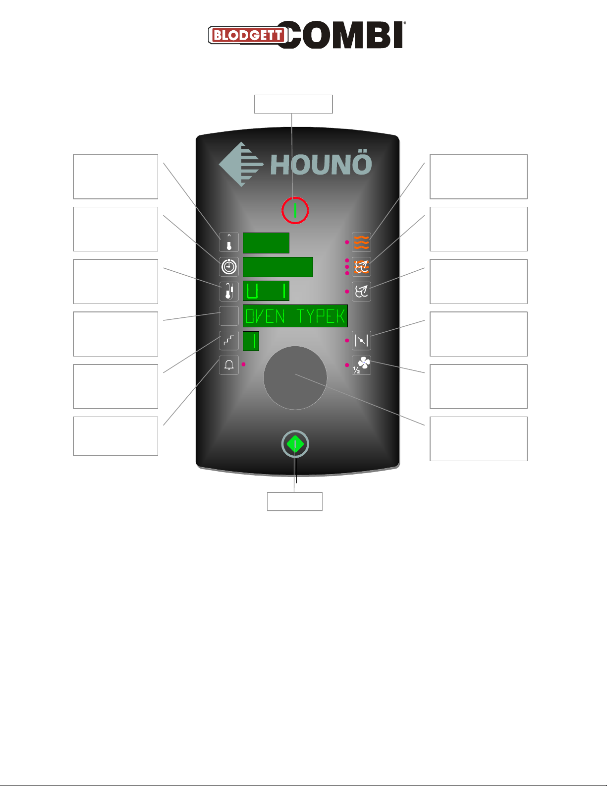
Start Menu
Program key
Step key
Alarm key
Start/Stop
Power Switch
Change oven
temperature with
turn switch
Change time with
turn switch
Core temperature
on C and K models.
Injection time on B
model.
PRG
HOT AIR selected if
control lamp on
COMBI STEAMING
selected if upper or
middle control lamp
is on. REHEATING is
selected if lower
control lamp is on
Steaming on C and
K, preheating on B
.
Exhaust open if
control lamp on
Fan speed can be
set between 20 and
100%. Control lamp
is on when speed
< 100.
Set temperature
(press temperature key, temperature flashes, set temperature with turn
switch, press temperature key again to save).
Set time
(press time key, time flashes, set time with turn switch).
Set core temperature
(press core temperature key, set temperature with turn switch).
Set injection time
(press injection key, time flashes, set injection time with turn switch). B
model only.
Turn switch
Page 8
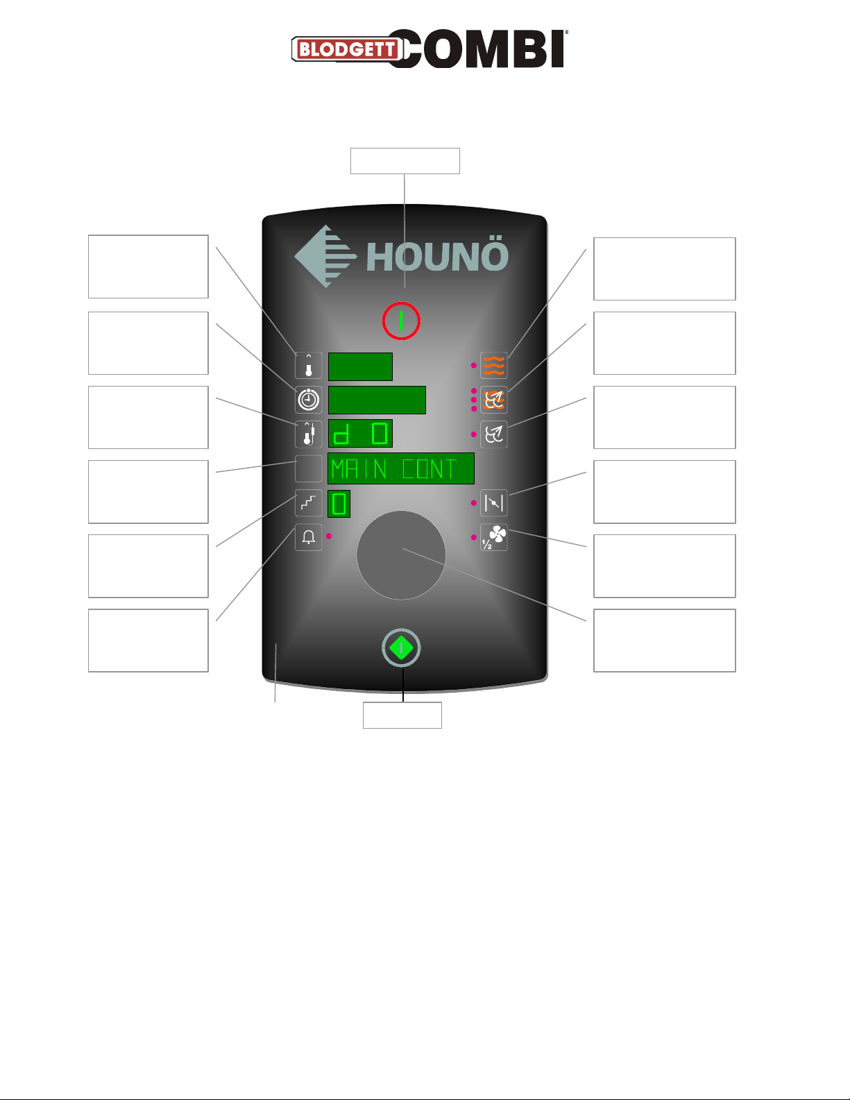
Oven set-up
Power Switch
Display shows
setting
Not active
Display shows "U"
No.
Display shows
description of "U"
function
Display shows
setting
Confirmation of
special settings
PRG
Press HOT AIR and
STEAMING for 2 sec.
Possible to change to
"d" test mode with
combi steam key
Press STEAMING/
PREHEATING and
HOT AIR for 2 sec.
Not active
Not active
Select "U" settings
with turn switch
Not active
To enter set-up mode, press hot-air key and steaming/preheating key for 2 sec.
To leave set-up mode, turn switch to the left. Change between set-up and test mode by
pressing combi-steam key.
The set-up mode is only intended for service engineers who wish to change the set-up of the
computer control of the oven model in question.
The program display shows a description of the "U" function in question.
Page 9

Set-up Mode U
In the set-up function, it is possible to set the oven controller to match the mechanical set-up and
the choice of software.
If the set-up has been changed in U1, U4 or U15, the oven will be reset.
U1 Oven model
You select the oven model (B, C or K) by pressing the step key.
1= K, 2= C, 3= B.
You press the temperature key to select a PassThrough model (two doors).
1= one door (standard) 2= two doors
When you have selected the oven model, confirm by pressing the alarm key if the control lamp
flashes.
After that, the controller initializes.
NOTE: ALL settings and programs are reset.
U2 Oven size
You choose the oven size by pressing the step key: 0-7.0= 1.06, 1= 1.08, 2= 1.10, 3= 1.12, 4=
1.16, 5= 1.20, 6= 2.10, 7= 2.14.
The oven size you have chosen is shown in the field next to the temperature key.
U3 CombiWash
You activate or deactivate CombiClean by pressing the step key.
0=OFF, 1=ON.
U4 Temperature scale
You choose between Celsius and Fahrenheit as scale of temperature by pressing the step key.
0= Celsius 1= Fahrenheit.
You can ”even out” the current temperature by pressing the temperature key.
0=OFF, 1=ON
When you have chosen the temperature scale, confirm by pressing the alarm key if the control lamp
flashes.
After that, the controller initializes.
NOTE: ALL settings and programs are reset.
U5 Not in use
U6 Low-temperature steaming
You activate and deactivate low-temperature steaming by pressing the step key.
0= OFF, steaming only possible at 100°C, 1= ON, steaming only possible between 30°C and 120°C.
NOTE: This function is available on K models only. If chosen on a B or C model, nothing
happens.
U7 Preheating at 300°C
You activate and deactivate preheating by pressing the step key.
0= OFF, 1= ON.
NOTE: Preheating at temperatures above 250°C is only possible for max. 15 minutes.
U8 Setting water level sensor
When you press the temperature key, the water level value starts flashing and can then be set
between 40 and 80 (default 70).
If the conductivity of the water is low, set the water level higher.
U9 Automatic restart
You activate and deactivate automatic restart by pressing the step key.
0= OFF, 1= 10 minutes, 2= 30 minutes, 3= 60 minutes.
This means that if there is a power cut, the program that was interrupted will be reassumed provided
that the power returns within the time set.
- 9 -
Page 10

U10 Programs
You activate the program mode by pressing the step key.
0= OFF, 1= 10 programs with 3 process steps.
NOTE: It is still possible to activate the cleaning program even though the program mode
is not active.
0= OFF.
U11 Core temperature probe
You activate and deactivate the core temperature probe by pressing the step key.
0= OFF, 1= ON.
U12 Drain cooling
You activate and deactivate drain cooling by pressing the step key.
0= OFF, 1= ON.
U13 Timer start
You activate or deactivate timer start by pressing the step key.
0= OFF, 1= ON.
U14 Demo
You activate or deactivate the demo mode by pressing the step key.
0= OFF, 1= ON.
NOTE: If the demo mode is on (1= ON), the oven will run without heating elements and
steam generator being switched on.
When the oven starts, it will let you know whether the demo mode is on.
U15 Initialising
You reset the controller by pressing the alarm key.
- 10 -
Page 11
Power Switch
Display shows
setting
Display shows
setting
Test Mode
For test mode, press
HOT AIR and COMBI
STEAMING for 2 sec.
For test mode, press
COMBI STEAMING and
HOT AIR for 2 sec.
Display shows "d"
No.
Possible to change to
"U" setting by pressing
STEAMING/PREHEATING
Display shows a
description of the
"d" function
PRG
Not active
Display indicates
whether the
function is active
Not active
Activates each
function briefly
Possible to choose a
"d" function with turn
switch
Not active
To enter test mode, press hot-air key and combi-steam key for 2 sec.
To exit test mode, turn switch left. Change between set-up mode and test mode by pressing
steaming/preheating key.
How to operate the selected component: You turn the component on (1) and off (2) by pressing
the step key. Or, you press the alarm key, and the component is active for as long as you press
the key.
The set-up mode is only intended for service engineers who wish to test the various
modes/functions.
Page 12

Test Mode D0-D6
In the test mode, it is possible to activate all electrical components. This is very useful in connection
with fault detection and the testing and adjusting of replacement parts.
D0 Main contactor(s)
This function activates contactor K1.
You activate or deactivate the function by pressing the step key. The function can, however, only be
activated when the fan is on.
To pulse, press the alarm key.
0= OFF, 1= ON.
Status for the main alarms appear in the display as follows:
Digit 1 fan
Digit 2 oven
Digit 3 generator
Digit 4 Solid State Relay
If ER28 appears, the alarm sensor circuit board or wiring harness is defective.
D1 Oven heat
This function activates contactor K2.
You activate or deactivate the function by pressing the step key.
Humidity pulsing is possible by pressing the alarm key.
0= OFF, 1= ON.
D2 Steam generator heat
Available on K models only
This function activates contactor K3.
You activate or deactivate the function by pressing the step key. However, this function can only be
activated when there is water in the steam generator.
To pulse, press the alarm key.
0= OFF, 1= ON.
D3 Fan, right-hand, high/low
This function activates the frequency exchanger.
You can test the speed of the motor by pressing the step key.
0= OFF, 2= ON
By pressing the time key, it is possible to adjust the speed of the motor from 0 to 100%.
The RPM appears in the temperature display.
Note: The main contactor K1 must be active for this function to work, as the frequency
transformer is connected via K1
D4 Fan, left-hand, high/low
This function activates the frequency exchanger.
You can test the speed of the motor by pressing the step key.
0= OFF, 2= ON
By pressing the time key, it is possible to adjust the speed of the motor from 0 to 100%.
The RPM appears in the temperature display.
Note: The main contactor K1 must be active for this function to work, as the frequency
transformer is connected via K1
D6 Solenoid valve
This function activates solenoid valve MV1.
You activate or deactivate the function by pressing the step key
To pulse, press the alarm key.
0= OFF, 1= ON.
- 12 -
Page 13

Test Mode D7-D15
D7 Filling valve
Available on K models only.
This function activates solenoid valve MV2.
You activate or deactivate the function by pressing the step key.
To pulse, press the alarm key. 0= OFF, 1= ON.
D8 Drain pump
Available on K models only.
This function activates motor M2.
You activate or deactivate the function by pressing the step key.
To pulse, press the alarm key. 0= OFF, 1= ON.
D9 Drain cooling
This function is not available on B models.
This function activates solenoid valve MV3.
You activate or deactivate the function by pressing the step key.
To pulse, press the alarm key. 0= OFF, 1= ON.
D10 Damper motor
This function activates motor M3.
In the display next to ”Time”, it is possible to read the status of the damper motor switch.
OFF= damper open, ON= damper closed.
You activate or deactivate the function by pressing the step key.
To pulse, press the alarm key. 0= OFF, 1= ON.
D11 Exhaust
This function activates the outlet for controlling the external ventilation, terminals 4 and 5.
In the display next to ”Time”, it is possible to read which outlet is active.
OFOF= both outlets are off, ONOF= outlet 4 is active and outlet 5 is off.
OFON= outlet 4 is off and outlet 5 is active. ONON= both outlets are active.
You activate or deactivate the function by pressing the step key.
0= OFOF, 1= OFON, 2= ONOF, 3= ONON.
D12 Cooling fan
This function activates motors M7 and M7A.
You activate or deactivate the function by pressing the step key.
To pulse, press the alarm key.
0= OFF, 1= ON.
D14 Interior light
This function activates H1.
You activate or deactivate the function by pressing the step key.
To pulse, press the alarm key.
0= OFF, 1= ON.
D15 Oven temperature
Here it is possible to read the current oven temperature, P1.
In the field next to ”Temperature”, the current temperature is shown. If ERR appears, the sensor
circuit is defective.
In the field next to ”Time”, an adjustment value between 80 and 120 (default 100) is shown.
To adjust the temperature, press the time key until the digit in the display flashes. Then adjust
upwards or downwards until the correct temperature is shown. Finally, press the time key again to
save the setting.
The temperature can be adjusted by +- 50°F (10°C).
- 13 -
Page 14

Test Mode D16-D20
D16 Core temperature
This function is not available on B models.
C and K models can use only one core temperature probe, it is possible, however, to test
core temperature probes 1 and 2.
Here it is possible to read the current temperature of the core temperature sensor, P2 + P2A.
In the field next to ”Temperature”, the current temperature is shown. If ERR appears, the sensor
circuit is defective.
In the field next to ”Time”, an adjustment value between 80 and 120 (default 100) is shown.
To adjust the temperature, press the time key until the digit in the display flashes. Then adjust
upwards or downwards until the correct temperature is shown. Finally, press the time key again to
save the setting.
The temperature can be adjusted by +- 50°F (10°C).
You change between the various measuring points of the core temperature probe by pressing the
step key.
1= Core temp probe 1, point 1, 2= Core temp probe, point 2, 3= Core temp probe 1, point 3.
4= Core temp probe 2, point 1, 5= Core temp probe, point 2, 6= Core temp probe 2, point 3.
D17 Steam generator temperature
Available on K models only.
Here it is possible to read the current steam generator temperature, P3.
In the field next to ”Temperature”, the current temperature is shown. If ERR appears, the sensor
circuit is defective.
In the field next to ”Time”, an adjustment value between 80 and 120 (default 100) is shown.
To adjust the temperature, press the time key until the digit in the display flashes. Then adjust
upwards or downwards until the correct temperature is shown. Finally, press the time key again to
save the setting.
The temperature can be adjusted by +- 50°F (10°C).
D18 Drain temperature
Here it is possible to read the current steam generator temperature, P4.
In the field next to ”Temperature”, the current temperature is shown. If ERR appears, the sensor
circuit is defective.
In the field next to ”Time”, an adjustment value between 80 and 120 (default 100) is shown.
To adjust the temperature, press the time key until the digit in the display flashes. Then adjust
upwards or downwards until the correct temperature is shown. Finally, press the time key again to
save the setting.
The temperature can be adjusted by +- 50°F (10°C) (approx. 2°F (.5°C) per step).
D20 Door sensor
Here it is possible to read the status of and calibrate door sensor 1 = SE1 and 2 = SE1A.
You change between door sensor 1 and 2 by pressing the step key.
After some time, the text “DOOR SENSOR” changes to show the status of the sensor: >CLOSED<,
>OPEN<, >SENS ERROR<. You start the calibration by pressing the exhaust key.
How to calibrate:
1. Press the damper key
2. >CLOSE< flashes
3. Close the door
4. Press the damper key
5. >OPEN< flashes
6. Open door in the first step
7. Press the damper key
8. >CALIB OK< or >CALIB ERR< appears
9. Press the damper key to confirm
In the display next to the temperature key, it is possible to read the current value (0 – 120).
In the display next to the time key, it is possible to read the set point.
- 14 -
Page 15

Test Functions D21-28
D21 Water level
Available on K models only.
Here it is possible to read the status of SE2.
In the display next to ”Time”, the conductivity is shown and it is indicated whether the water level is
high or low
XX|LO= low water level, XX|HI= high water level.
XX = conductivity of the water.
Default setting is approx. 80 with no water and 40.60 with water. The better the conductivity, the
lower the measured value.
D22 Thermo-switch oven
Here it is possible to read the status of Q1 and Q1A.
In the display next to ”Time”, it is shown whether the circuit is connected or disconnected.
OF= disconnected ON= connected.
In the event of defects, it is possible to reset thermo-switches Q1 and Q2 that are located at the
bottom of the oven below the operation panel.
Note: Q2 is only found in ovens with 2 fan motors (1.16 and 1.20). Q1 and Q1A are series
connected which is why there is only one input signal.
D23 Thermo-switch fan
Here it is possible to read the status of S2 and S2A
In the display next to ”Time”, it is shown whether the circuit is connected or disconnected.
OF= disconnected ON= connected.
In the event of defects, wait for 10 – 20 minutes, then try again.
Note: Q2 is only found in ovens with 2 fan motors (1.16 and 1.20). S1 and S1A each have
their own input on the IO board hence 2 x status (On On / OFF OF / On OF / OF On).
D24 Damper switch
Here it is possible to read the status of M3.
In the display next to ”Time”, it is possible to read the status of the damper motor switch.
OF= damper open, ON= damper closed.
D27 Pump for detergent
Only possible on ovens with CombiWash
This function activates pump M5.
You activate or deactivate the function by pressing the step key.
To pulse, press the alarm key.
0= OFF, 1= ON.
D28 Pump for rinse aid
Only possible on ovens with CombiWash
This function activates pump M6.
You activate or deactivate the function by pressing the step key.
To pulse, press the alarm key.
0= OFF, 1= ON.
- 15 -
Page 16

Test Mode D29-D47
D29 CombiWash water
Only possible on ovens with CombiWash.
This function activates solenoid valve MV4.
You activate or deactivate the function by pressing the step key.
To pulse, press the alarm key.
0= OFF, 1= ON.
D34 Water pressure sensor
Here it is possible to read the status of P7.
OF|HI= water pressure adequate, ON|LO= water pressure inadequate.
D36 Steam generator thermo-switch
Here it is possible to read the status of Q3
In the display next to ”Time”, it is shown whether the circuit is connected or disconnected.
OF= disconnected ON= connected.
In the event of defects in the oven, it is possible to reset thermo-switch Q3 which is located at the
bottom of the oven below the operation panel.
D37 Motor RPM 1
Here it is possible to read the number of revolutions for fan motor 1.
The number of revolutions is shown in the display next to the temperature key.
D38 Motor RPM 2
Available on 1.16 and 1.20 models only.
Here it is possible to read the number of revolutions for fan motor 2.
The number of revolutions is shown in the display next to the temperature key.
D46 Temperature CPU board
Here it is possible to read the temperature of the CPU board.
In the display next to ”Temperature”, the temperature of the CPU board is shown. Max 140°F
(60°C).
D47 Temperature IO board
Here it is possible to read the temperatures of the IO board.
In the display next to ”Temperature”, the temperature of the IO board is shown. Max 140°F (60°C).
- 16 -
Page 17

Turn switch
Main switch
Start/Stop
User Menu
Display shows
setting
Display shows
setting
Display shows "b"
No.
Display shows
description of "b"
function
Display shows
setting
Press key for 5 sec.
to access user
menu
Not active
Not active
Not active
PRG
Not active
Not active
To enter user menu, press alarm key for 5 sec.
To exit user menu, turn the switch to the left.
The user menu can be operated by the end-customer as well as by the service engineer.
Page 18

User Menu B1-B7
B1 Save pre-settings
In this function, you save the preset time and temperature.
If, for instance, the end user uses HOT AIR at 180°C for 30 minutes, the standard setting can be
changed as follows:
1. Change time and temperature.
2. Enter user menu (keep pressing alarm key for 5 sec.)
3. Select B1 (save pre-settings).
4. Press alarm key to accept.
You can only save the settings when the control lamp next to the alarm key flashes.
B2 Timer start
(Please see user manual)
B3 Sound level low
In this function, you adjust the sound that is heard when a key is activated. The sound level can be
adjusted from 0 to 9 (0 is no sound at all).
You adjust the sound level by pressing the step key.
B4 Sound level high
In this function, you adjust the sound that comes from the alarm. The sound level can be adjusted
from 1 to 9 (1 is very low).
You adjust the sound by pressing the step key.
B5 Sound frequency
In this function, you adjust the sound frequency.
The sound frequency can be adjusted from 1 to 9.
You adjust the sound by pressing the step key.
You test the sound by pressing the alarm key.
B6 Interior light
In this function, you adjust the interior light.
The light can be set at 0 or 5.
0= Light is always on.
5= Light goes out when the oven has been idle for 5 minutes.
You adjust the interior light by pressing the step key.
B7 Current temperature
In this function, you choose whether the oven should display the current temperature or the preset
temperature.
You choose between 0 and 1
0= The preset temperature is shown.
1= The current temperature is shown.
You change the setting with the step key.
- 18 -
Page 19

User Menu B8-B13
B8 Exhaust
In this function, you choose whether the oven should start up the extraction hood.
0= Extraction hood not controlled by oven
1= Extraction hood runs for 10 minutes after oven has stopped.
This applies to an extraction hood mounted on the oven as well as for an external extraction hood.
B9 Time graphics
In this function, you determine whether the oven should be able to show graphically how long time
has passed of a cooking sequence.
You choose between 0 and 1.
0= No graphics
1= Graphics, for instance ”llllll------”, appear
You change the setting with the step key.
B10 Minutes
In this function, you set the minutes of the oven’s clock.
1. Press the key next to the temperature display (digit flashes).
2. Turn the switch to the desired setting of minutes.
3. Press the key next to the temperature display (digit stops flashing)
You can set the minutes from 0 to 59.
The oven’s clock may appear as screen saver.
B11 Hours
In this function, you set the hours of the oven’s clock.
1. Press the key next to the temperature display (digit flashes)
2. Turn the switch to the desired setting of hours.
3. Press the key next to the temperature display (digit stops flashing)
You can set the hours from 0 to 23.
The oven’s clock may appear as screen saver.
B12 Day/weekday
In this function, you set the day of the month and of the week.
1. Press the key next to the temperature display (digit flashes)
2. Turn the switch to the desired day of the month (1-31).
3. Press the key next to the temperature display (digit stops flashing)
4. Press the key next to the time display (digit flashes)
5. Turn the switch to the desired day of the week (1-7).
6. Press the key next the time display (digit stops flashing)
You select automatic updating to summer time.
0= No automatic updating to summer time.
1= Automatic updating to summer time.
If you choose not to have the oven update to summer time automatically, you cannot set the
weekday.
Automatic updating to summer time only functions correctly in Western Europe.
B13 Month
In this function, you set the month.
1. Press the key next to the temperature display (digit flashes).
2. Turn the switch to the desired month.
3. Press the key next to the temperature display (digit stops flashing).
You can set the month from 1 to 12.
- 19 -
Page 20

User Menu B14-B21
B14 year
In this function, you set the year.
1. Press the key next to the temperature display (digit flashes).
2. Turn the switch to the desired setting.
3. Press the key next to the temperature display (digit stops flashing).
You set the year from 6 to 20.
B15 CombiWash
In this function, you activate or deactivate CombiWash.
0= Manual cleaning
1= CombiWash
Press step key to change setting.
B16 Pulsing interval, reheating
In this function, you set the pulsing time in the reheating mode.
1. Press the key next to the temperature display (digit flashes).
2. Turn the switch to the desired time.
3. Press the key next to the temperature display (digit stops flashing)
You set the time from 5 – 50 sec.
B17 Pulsing interval, Combi Steam 1
In this function, you set the pulsing time for Combi Steam 1.
1. Press the key next to the temperature display (digit flashes).
2. Turn the switch to the desired time.
3. Press the key next to the temperature display (digit stops flashing)
You set the time from 2 to 50 sec.
B18 Pulsing interval, Combi Steam 2
In this function, you adjust the pulsing time for Combi Steam 2.
1. Press the key next to the temperature display (digit flashes).
2. Turn the switch to the desired time.
3. Press the key next to the temperature display (digit stops flashing)
You set the time from 1 sec. to the number of seconds specified to be the pulsing time for Combi
Steam 1.
B19 Save all (Backup)
In this function, you save set-up and programs to the IO board for subsequent restoration. This can
be used as backup when set-up and programs are correct.
Press alarm key to save.
B20 Restore all
In this function, you restore set-up and programs you have saved earlier.
B21 Restore original
In this function, you restore the original programs from 0 to 4.
1. Press step key to select program.
2. Press alarm key when program has been found.
- 20 -
Page 21

User Menu B22-B24
B22 Screen saver
In this function, you set the time that should pass until the clock appears in the display. Press step
key to select time.
0= no screen saver
1= 10 sec.
2= 30 sec.
3= 60 sec.
4= 180 sec.
5= 600 sec.
The screen saver appears when the oven has been idle for a particular period of time.
B23 Language
In this function, you change the language of the computer.
Press step key and select 1, 2, 3 or 4. There are also four language variants: A – D (see below).
To change the language, you need to update again (see B24)
B24 Software update
In this function, you update the computer software by means of a special memory key (not a USB
key).
1. Insert memory key.
2. Press alarm key to view software version and language variants.
3. Press step key to select language variant.
4. Press alarm key again to start updating process.
The software version of the oven in question is also shown in the start-up sequence when the oven is
switched on.
1 Danish English English English
2 Swedish German French Estonian
3 English Kroatian Spanish Hungarian
4 Finnish Slovenian Italian Russian
A B C D
Page 22

Display shows error
"Er" No
Display shows
description of error
PRG
Error codes
Main switch
Start/Stop
All keys can be used to acknowledge an error message.
Turn switch
Page 23

by pressing button under oven.)
by pressing button under oven.)
minutes and try again.
Drain too hot
(Drain temperature has been above 75
°
C for more
than 5 min. Check that jet in drain is working.)
working properly.)
probe has been selected but probe has not been connected.)
working.)
be used.)
Check that the water has been turned on.)
130°C. If fault recurs, descale generator)
Error code 14:
FAN SPEED
Fan running too slow
Error code 18:
DATA ERROR
Error in set
-
up data
Error code 19:
WRONG LANG
Wrong language
board.)
Error code 22:
NO RESTART
Restart not possible
(Oven has been without power too long.)
Error code 23:
OVEN WARM
Oven too hot at CombiWash start
-up
the core temperature probe defective.)
Error code 28:
ALARM ERR
Configuration error in main alarms
(3, 4, 5, 12) (warning)
Error code 34:
WATER PRES
Water pressure too low
(Check that water is turned on.)
Error code 40:
IO BRD HOT
Temperature in IO board critical
(Warning after program run.)
Error code 43:
WRONG SW
Wrong software version
(Visual Cooking I oven)
Error code 44:
DAMPER ERR
Failure during initialisation of exhaust at oven start
-up
Error code 3: GENRA HOT
Error code 4: OVEN HOT
Error code 5: FAN HOT
Error code 6: DRAIN > 75
Error code 7: OVEN SENS
Error code 8: PROBE SENS
Error code 9: GENER SENS
Error code 10: DRAIN SENS
Error code 11: WATER SHOR
Error code 12:
Error code 13: GENER > 130
SSR HOT SSR too hot (Solid-state relay too hot.)
Error codes
Generator too hot (Generator thermo switch has tripped. Reconnect
Oven too hot (Oven chamber thermo switch has tripped. Reconnect
Fan too hot (Thermo switch in motor has tripped. Wait for 10
Oven sensor defective (Temperature sensor in oven chamber not
Core temp. probe not connected (A program using core temp.
Generator sensor defective (Temperature sensor in generator not
Drain sensor defective (Sensor in drain not working. Oven can still
Water shortage (Steam generator was not filled within two minutes.
Generator too hot (Temperature in steam generator higher than
Error code 15:
Error code 16: IO BRD HOT IO board too hot (> 60°C)
Error code 20: NO COM IO
Error code 24: DRAIN ERR
Error code 25: PROBE ERR
Error code 29: DOOR SENS Wrong door sensor signal (warning)
CPU HOT CPU board too hot (> 60°C)
Internal defect (Failure in communication between computer and IO
Draining failure (Drain blocked or failure of drain pump. Water level
in generator still high after 10 seconds of draining.)
Core temperature probe defective (1, 2 or 3 of the elements in
Page 24

Notes:
________________________________________________________________________
________________________________________________________________________
________________________________________________________________________
________________________________________________________________________
________________________________________________________________________
________________________________________________________________________
________________________________________________________________________
________________________________________________________________________
________________________________________________________________________
________________________________________________________________________
________________________________________________________________________
________________________________________________________________________
________________________________________________________________________
________________________________________________________________________
________________________________________________________________________
________________________________________________________________________
________________________________________________________________________
________________________________________________________________________
________________________________________________________________________
________________________________________________________________________
________________________________________________________________________
________________________________________________________________________
________________________________________________________________________
________________________________________________________________________
________________________________________________________________________
________________________________________________________________________
________________________________________________________________________
________________________________________________________________________
Page 25

BCP & BCM, ERROR CODES & CAUSES
3 - Generator Hot – Generator High Limit Thermostat Open(Opens at 275˚F) (Manual Reset under a
cover at the bottom of the control panel)
4 – Oven Hot - Oven High Limit Thermostat Open (Opens at 662˚F) (Manual Reset under a cover at the
bottom of the control panel)
5 – Fan Hot – Motor Thermal Limit Open (2 Gray Wires) (Opens at 320˚F) Wait 10 minutes and try again.
If 5 appears again, the cooling fans, motor bearings, or thermal switch within the motor failed.
6 – Drain Hot – RTD Probe in Drain (100 Ohm Probe) reads over 167˚F for over 5 minutes.
7 – Oven sensor Defect – RTD Probe in Generator (100 Ohm Probe) Shorted/Open
8 – Core Probe Missing – Control has an active Core (Meat) Probe. Deactivate both Core Probes or
insert Core Probe in the probe port on the control side.
9 – Gen Sensor Defect – RTD Probe in Generator (100 Ohm Probe) Shorted/Open
10 – Drain Sensor Defect - RTD Probe in Drain (100 Ohm Probe) Shorted/Open
11 – Water Shortage – Steam Generator could did fill in 5 minutes.
12 – SSR Hot – one of the two SSR Heat Sink Automatic Reset Snap Disks that are wired in series is Open
(Open at 248˚F)
13 – Generator > 265 – RTD Probe in Generator (100 Ohm Probe)reads over 265˚F.
14 – Fan Slow – Fan Hall Sensor (Brown, Black and Red Wires), Inverter or the Motor has failed or a
wiring issue exists.
16 – IO Board Hot – The IO Board senses a temperature above 140˚F.
19 –Internal Error–The control has sensed a failed process, restart the control.
20 – IO Com Error- Failure of communication between the CPU and IO Board.
21 – Invalid recipe – Indicates a recipe is programmed for a feature the oven does not have.
22 - Program Terminated – Power interrupted while a program was in progress and enough time
elapsed that the program cannot resume.
24 – Empty Error – Steam Generator water level sensor reads water 25 seconds after running the drain
pump to drain the boiler.
25 – CombiOptima not Calibrated – Enter the Service Menu and run the calibration.
26 – CombiOptima Sensor Error – The Pressure sensor gives a reading outside the range of 0.5 - 4.5.
27 – CombiOptima calibr. Fault – Calibration could not be completed, Start calibration when the oven is
cold and dry.
Page 26

BCP & BCM, ERROR CODES & CAUSES
28 – Main Alarm Error –No 24V signal to high limit board
29 – Door Sensor Error – Wrong door sensor signal
34 – Water Pressure Low – Water Pressure Switch (located on the larger solenoid assembly) is closed.
(Opens at 22 PSI)
36 – No Detergent – Time Based detergent monitoring is disabled.
38 – Detergent In Oven – Combi wash interrupted while the detergent was in the oven. Run Combi
Wash in Step 0 to clear detergent prior to inserting product.
39 – Insufficient Memory – The units memory is not sufficient for the current operation.
40-IO Board Hot- The IO Board senses a temperature above 140°F.
41 – Main Alarm -
42 – Error in SW – Software Error. Reboot software to current version.
For Gas Ovens
44-Dammper Error-Failure during initialization of exhaust at oven start-up.
45-24V Error-24V missing or failure of main contactor output.
50-Switch On-Pressure switch on when gas-air control unit running (timeout 20 sec.)
51-Switch Off-Pressure switch not on when gas-air control unit running (timeout 20 sec.)
52-Gas Valve-Gas valve does not open (automatic gas burner control has failed (timeout 20 sec.))
53-No Fan RPM-Gas-air control unit does not revolve when pressure switch is on.
54-Fan Error-Gas-air control unit does not run at correct RPM just before ignition.
55-Gas Fail-Warning: Ignition failed.
56-Gas Error-Flame fails to occur after 3 attempts.
57-Gas Stop-Warning: Gas failure during operation.
Page 27

BLODGETT OVEN COMBI
1
Sequence of Operation for BCP and BCM (electric)
Unit is turned “OFF”
You will have AC voltage at:
• The bottom of the main contactor (T1, T2, T3)
• Fuse F5 in the front
• The transformer (T1) in the front of the oven
• Fuse F1, F2, F3 and F4 in the front
• On the CPU and the IO board (J10 pin 5 and 6)
There are no DC voltage when the unit is turned OFF
Unit is turned “ON”
• The boot logo appear on the screen for about 30 sec. then ready to
operate (only BCP)
• Light will come on after 30 sec.(only BCP) (12 VAC between J9 pin 3 and
terminal 1)
• The exhaust valve will “open” and “close” after 30 sec. (24 VAC between
J2 pin 12 and terminal 1) (Ground J2 pin 15 when closed)
When a mode is started
The IO board verifies the following with DC voltage:
• The door sensor SE1 is closed sending either towards 0 or towards 5
DC voltage to J1 pin 34 depending on the pole of the magnet.
• With door sensor SE1 open the DC voltage is 2,5 on J1 pin 34.
The IO board verifies the following with AC voltage:
• The high limit stat of the motor is closed sending 24 VAC to J1 pin 10
• The high limit stat of the oven is closed sending 24 VAC to J1 pin 9
• The high limit stat of the boiler is closed sending 24 VAC to J1pin 12
• The high limit stat of the SSR closed sending 24 VAC to J1 pin 13
• Main contactor K1 is activated (24 VAC on coil of contactor A1 and A2)
output from IO board is coming from plug J2 pin 2 going through all the
high limit stats and to the coil.
• When the main contactor is activated the terminal L4 on the contactor
provides power to the frequency inverter (terminal L/R) which controls
the motor M1.
• The IO board makes a connection between J2 pin 28 and 27 to terminal
+12V, and Start, this will start the fan.
• The speed of the fan depends of the DC voltage on terminal Com and
Speed of the inverter (IO board J2 pin 33 and 34) 0 – 10 VDC
• The motor reverses direction every 2 minutes by making a connection to
the terminal REV of the inverter (IO board J2 pin 29) +12VDC
Page 28

BLODGETT OVEN COMBI
2
Unit set in “Hot air”
Max temperature 250°C/482°F
• The SSR gets DC voltage on the terminal -/+1 (if boiler model) -/+1 and
2 (if no boiler) DC coming from J2 pin 22 and 23.
• The IO board will get a resistance input from P1 (oven temperature
sensor PT100) on J1 pin 37 and 38 telling the IO board when to switch
off the SSR.
• When the time runs out H2 (buzzer) will be activated.
Unit set in “CombiOptima”
• The SSR gets DC voltage on the terminal -/+1 (if boiler model) -/+1 and
2 (if no boiler) DC coming from J2 pin 22 and 23.
• The IO board will get a resistance input from P1 (oven temperature
sensor PT100) on J1 pin 37 and 38 telling the IO board when to switch
off the SSR.
• The sensor P9 is supplied by 12 VDC from J1 pin 25 and 26.
• The sensor measure pressure between 0 – 3 mbar (0,5 – 4,5 VDC)
• Depending on the temperature/fan speed/pressure the computer
calculates the humidity.
• The higher temperature the lower pressure (voltage)
• The higher humidity the lower pressure (voltage)
• Dry and cold oven gives the highest reading (voltage)
(There are no precise measures/voltages it depends on the oven. That is why it
has to be calibrated.)
Page 29

BLODGETT OVEN COMBI
3
Unit set in “Steam”
Max temperature 100°C/212°F, Forced steam 120°C/348°F
• If P3 (temperature sensor of boiler PT100) register an Ohm value which
is higher than 65°C/149°F it will start filling to HIGH level. If the value is
lower than 65°C/149°F empty and flush the boiler as described below.
• The empty pump M2 gets 208V/230V signal from J11 pin 4 and F6.
• The boiler will now get flushed this is the sequence:
1. Empty boiler 25/35/45 sec. depends on the boiler size
2. Empty boiler 5 sec. and filling 5 sec.
3. Empty boiler 10 sec.
4. Empty boiler 5 sec. and filling 5 sec.
5. Empty boiler 10 sec.
6. Empty boiler 5 sec. and filling 5 sec.
7. Filling 5 sec.
8. Filling to high level
9. Wait 2 sec. check level again
Ready the run the boiler
• The boiler will be filled by MV2 (filling valve) get 24 VAC from J2 pin 10
• The level sensor SE2 is supplied by 12 VDC when the sensor give a
ground signal to J1 pin 33 the IO board will cut off the MV2 valve.
• When the HIGH level is registered, the SSR gets DC voltage on the
terminal -/+2 DC coming from J2 pin 22 and 25 to heat up the water.
• If the level sensor register LOW level (not ground signal on J1 pin 33)
during boiling the MV2 (filling valve) will be activated 3 times for X sec.
• If the IO board does not register HIGH level with in the 3 tries, MV2 will
be activated continuously until HIGH level is reached.
• Temperature in drain P4 J1 pin 47 and 48 above 65°C/149°F, active MV3
24 VAC (J2 pin 11) will cool down until the temperature is below
60°C/140°F.
• When the time runs out H2 (buzzer) will be activated.
Unit set in “Reheating”
Temperature 20°C/68°F to 180°C/356°F
• Standard fan speed 50% (5 VDC on inverter terminal Com and Speed, IO
board J2 pin 33 and 34)
• As standard inject water every 8 sec. for 1/10 of sec. through MV1
(injection valve) 24 VAC (IO board J2 pin 8)
• Temperature in drain P4 J1 pin 47 and 48 above 65°C/149°F, active MV3
24 VAC (J2 pin 11) will cool down until the temperature is below
60°C/140°F.
• When the time runs out H2 (buzzer) will be activated.
*Standard settings can be changed in setup
Page 30

BLODGETT OVEN COMBI
4
Unit set in “Proving” (Only BCP)
• Standard fan speed 50% (5 VDC on inverter terminal Com and Speed, IO
board J2 pin 33 and 34)
• As standard inject water every 20 sec. for 1 sec. through MV1 (injection
valve) 24 VAC (IO board J2 pin 8)
• When the time runs out H2 (buzzer) will be activated.
*Standard settings can be changed in setup
Unit set in “Cooling down” (Only BCP)
The IO board registers if the door sensor is OPEN or CLOSED.
• If the door sensor registers OPEN 2,5 VDC on J1 pin 34, the fan M1 will
be on 100% speed (10 VDC on inverter terminal Com and Speed, IO
board J2 pin 33 and 34) until the temperature selected is reached.
• If the door sensor registers CLOSED either towards 0 VDC or towards 5
VDC on J1 pin 34, the fan M1 will be on 100% speed. If the temperature
is above 150°C/302°F the MV1 (injection valve) will be activated 24 VAC
(IO board J2 pin 8) for 0,1 sec. and then off for 1 sec. the sequence will
continue until the temperature is below 150°C/302°F.
• When the temperature is below 150°C/302°F the MV1 (injection valve)
will be activated for 1 sec. and then off for 1 sec. it will continue to run
this sequence until the temperature is reached.
• When the temperature is reached H2 (Buzzer) will be activated.
Unit set in “Preheating”
Max temperature 300°C/572°F
Max time 15 min.
Standard High speed
• The SSR gets DC voltage on the terminal -/+1 (if boiler model) -/+1 and
2 (if no boiler) DC coming from J2 pin 22 and 23.
• The IO board will get Ohm input from P1 (oven temperature sensor
PT100) on J1 pin 37 and 38 telling the IO board when the temperature is
reached, when it is reached it will stay on that temperature for the time
set.
• When the time runs out H2 (buzzer) will be activated.
Page 31

Front side B, C, K controller
Short
Power
5V
3.3V
24V AC
Testpins
Start IO
Keyboard
9. maj 2011
9. maj 2011
HOUNÖ A/S
HOUNÖ A/S
Dias 5
Dias 5
RS232
Encoder
CPU
reset
5V
Programming
connector
flash at
start-up
Com IO light diodes:
Yellow transmit
Green receive
Must flash
Clock: Must
flash (1 sec)
Power:
24V AC
Start IO
COM IO
Not used
Page 32

Back side B, C, K controler
Buzzer
Buzzer
Keyboard
Memory key
connector
Programming
connector
9. maj 2011
9. maj 2011
HOUNÖ A/S
HOUNÖ A/S
Dias 6
Dias 6
Power:Power:
1,2 1,2 -- COM IO COM IO
3 3 -- GNDGND
4 4 -- Start IOStart IO
5,6 5,6 -- 24V AC24V AC
Power
1 6
Battery
(3V)
Encoder
RS232
not used
Page 33

BCP / BCM Water Level Switch
Wire Side
pos
Sensor Side
24Vdc
- 1
Delime Pump Black
24Vdc+
2
Delime Pump Red
-------
3
Not used
130 Q1
4 High Limit stat Motor “G”
41 Q4
5 High Limit stat Motor “G”
86 SE2
6 (
Boiler Level sensor Black
)
77 P3
7 100k Ohm Boiler Probe
76 P3
8 100k Ohm Boiler Probe
69 P1
9 100k Ohm Cavity Probe
68 P1
10 100k Ohm Cavity Probe
88 SE3A
11
Not used
87 SE3
12 Speed sensor Motor “sig”
211 SE1
13 Speed sensor Motor 5V
-
90 X90
13
Not used
210 SE1
14 Speed sensor Motor 5V+
89 X30
14
Not used
94P912V+
15 (
Boiler level sensor Brown
92P912V
- 16 (Boiler level sensor Blue
)
Test Points
)
)
Sensor Power
Empty
Full
12 VDC
1.2 VDC
0 VDC
Plug X31:
Page 34

stic mode allows you to navigate through all components to test
Press and hold the Hot Air and Combi keys
t
display 1 to activate that component
Instructions to activate the chemical pump to prime it during the start up process.
Combi
the
ed
next to the
1 will be displayed
press the Stage key
without the oven
simultaneously
the
tage key again to deactivate it
and the chemical pump will activate
Diagno
mode. To activate diagnostic mode,
scroll the dial to the desired componen
stage key will
BCM START UP GUIDE
Diagnostic Mode
d - Level
them
displayed next to the PROG key and then press
, press the s
being in a cooking
for 2 seconds then
Stage key once. The
0 will be displayed.
Step 1. Press and hold the Hot Air and
The Display will now show d 0 next to
Step 2. Scroll the dial till d30 is display
The Display will show DELIME PMP
Step 3. Press the Stage key once,
When pump has been primed,
keys simultaneously for 2 seconds.
Probe key
next to the Probe key.
PROG key.
next to the stage key
once to 0 the pump will deactivate.
.
Press and
hold the Hot
Air & Combi
Keys for 2-3
seconds.
BCM Blodgett Combi Oven
Page 1
Page 35

Page 36

Page 37

Page 38

Page 39

Page 40

Page 41

Page 42

Page 43

Wiring diagram:
High limit
High limit
Page 1
circuit board
9. maj 2011
9. maj 2011
HOUNÖ A/S
HOUNÖ A/S
Dias 2
Dias 2
Oven light
Cooling fan,
empty pump
CombiWash
pump, vent.
Output
Supply
Com. to CPU
Input
Input to IO
board
To high limit
components
Page 44

Wiring diagram:
Page 2
9. maj 2011
9. maj 2011
HOUNÖ A/S
HOUNÖ A/S
Dias 3
Dias 3
Main
contactor
Please note main
connection direct
on main contactor
Main fuse for
transformer
fase
Main fuse for
transformer
neutral
Main terminals
neutral, earth
Ring element
Ø400 motor 1
Solid state
relay no. 1
Ring element
Ø470 motor 1
Ring element
Ø400 motor 2
Solid state
relay no. 2
Please note
this is only
for C - CPE
Ring element
Ø470 motor 2
Page 45

Connection
to main
contactor
Solid state
relay no. 1
Wiring diagram:
Page 3
Solid state
relay no. 2
Solid state
relay no. 3
Solid state
relay no. 4
9. maj 2011
9. maj 2011
HOUNÖ A/S
HOUNÖ A/S
Dias 4
Dias 4
Please note
this is only
for K - KPE
Ring element
Ø400 motor
M1
Ring element
Ø400 motor M2
Ring element
Ø470 motor
M1
Ring element
Ø470 motor M2
Element
steam boiler
Element
steam boiler
Temp. sensor
steam boiler
High limit steam
boiler 135°C
Top element
steam boiler
Element
steam boiler
Page 46

Connection to
main fuse F5
Connection to
neutral terminal
Fuse for detergent /
rins pump and vent.
Fuse for
interior light
Wiring diagram:
Page 4
Terminals on
main contactor
Transformer
Fuse for IO and
CPU board
Fuse for all
24V output
Frequency
inverter
9. maj 2011
9. maj 2011
HOUNÖ A/S
HOUNÖ A/S
Dias 5
Dias 5
Interior light
Plug on IO
board
Buzzer (Sound)
Plug on IO
board for com.
1. Main fan
2. Main fan (only
used on 1.16 and
1.20
Page 47

Wiring diagram:
Page 5
9. maj 2011
9. maj 2011
HOUNÖ A/S
HOUNÖ A/S
Dias 6
Dias 6
Plug on Alarm
sens print
Sensor for
water pressure
Switch for
exhaust
Sensor for
ClimaOptima
Restart
switch
Doorsensor
singel door
Level sensor
boiler
Oven temp.
sensor
Core probe
temp. sensor 1
Doorsensor if
Passthrough
Core probe
temp. sensor 2
Temp.
sensor drain
Connection
to temp.
sensor boiler
Page 48

Solenoid valve
SSR
filling boiler
Coil main
contactor
Wiring diagram:
Page 6
Lamp in restart
button
Solenoid valve
CombiWash
9. maj 2011
9. maj 2011
HOUNÖ A/S
HOUNÖ A/S
Dias 7
Dias 7
Plug on alarm
sens. print
High limit
boiler
High limit motor
2 only used in
1.16/1.20
High limit
motor 1
High limit
SSR if more
than 2 SSR
High limit
Connection to
fuse F1
Motor for
exhaust
Solenoid valve
drain
Solenoid valve
inject
High limit oven only
when 1.16/1.20
High limit
oven
Connections to solid
stat relay
Connections to
frequency inverter
Page 49

Wiring diagram:
Connection to
terminal 2 (ext. vent)
Page 7
Connection to
Fuse F5
9. maj 2011
9. maj 2011
HOUNÖ A/S
HOUNÖ A/S
Dias 8
Dias 8
Connection to
Fuse F3
Connection to
terminal 1
Rinse pump
Detergent pump
Connection to
Fuse F3
Connection to
neutral terminal
Cooling fan in the
top of tech. room
Connection to
Fuse F5
Empty pump
boiler
Cooling fan in the
back of tech. room
 Loading...